1
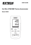
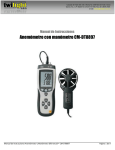
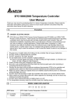
User Guide Heavy Duty CFM-CMM Thermo-Anemometer With built-in non-contact IR Thermometer and Laser Pointer Model HD300 Introduction Congratulations on your purchase of the Extech HD300 CFM Thermo-Anemometer. This handheld meter measures and displays air velocity, air flow (volume), temperature of air, and surface temperature (using the built-in non-contact IR thermometer). This meter is shipped fully tested and calibrated and, with proper use, will provide years of reliable service. Features CFM/CMM Thermo-Anemometer with built-in non-contact IR Thermometer measures remote surfaces to 932°F (500°C) with a 30:1 distance to spot ratio and Laser pointer. Simultaneous display of Air Flow or Air Velocity plus ambient temperature. Eight (8) memory locations permit the user to store multiple air duct AREA values for fast and easy recall. Twenty (20) reading average for Air Flow or Air Velocity. Large backlit LCD display. 3% velocity accuracy via low friction 2.83” (72mm) ball-bearing vane wheel on a 3.9‟ (120cm) cable. Data Hold and Max/Min/Avg. Auto Power OFF (can be disengaged). Safety Use extreme caution when the laser pointer beam is on Do not point the beam toward anyone's eye or allow the beam to strike the eye from a reflective surface Do not use the laser near explosive gases or in other potentially explosive areas 2 HD300-EN-V2.2 07/13 Meter Description 1. LED display for Air Velocity, Air Flow, Probe Temperature, and remote surface temperature. Units of measurement and user alerts are also displayed on the LCD. 2. Vane Sensor. Hold the sensor in the flow of air to take a reading. 3. IR sensor: Non-contact temperature measurement for remote surfaces. 4. Laser Pointer: Helps the user aim the IR sensor. 5. Battery access: Cover on rear panel 6. PC interface jack: Use the supplied cable to connect meter to a PC 7. Upper Keypad (brief descriptions below): IRT: Press and hold to measure remote surface temperature. Release to hold the temperature value on the display. MAX/MIN (for air temperature measurements): Used to record and store the highest and lowest readings for temperature measurements made by the vane probe. AVG: Used to obtain Average for multi-point measurements in either FLOW or VELOCITY modes. Up to twenty (20) points can be averaged. HOLD (for air temperature measurements): Press to freeze the displayed temperature reading measured by the probe. Press again to unlock the display. Press and hold for 2 seconds to activate the LCD backlight. Press and hold again for 2 seconds to turn the backlight off. 8. Lower Keypad On/Off button MAX/MIN (for air velocity and air flow): Press to record and store the highest, lowest and continuous moving average readings for single point measurements. This button also functions as the decimal positioning tool in the AREA mode. C-F UNITS : Press to select the mode of operation and unit of measure. In FLOW mode, the meter displays air volume. In VELOCITY mode, the meter displays air speed. This button also functions as the UP arrow button in AREA mode. AREA / NEXT: Press and hold to enter the AREA mode. The NEXT function allows the user to save AREA values to any of eight memory locations. This button is also used to clear stored readings in the MAX/MIN/AVG modes. : Press to turn the meter ON or OFF HOLD (for air velocity and air flow measurements) Backlight: Press to freeze the displayed air velocity or air flow reading. Press again to unlock display. This button also functions as the right arrow button in the AREA mode. NOTE: Battery Compartment and Tripod Mount are located on the reverse side of the meter 3 HD300-EN-V2.2 07/13 Operation Air Velocity Measurements Side view of Vane 1. Connect the sensor to the sensor input jack on top of the meter. 2. Turn ON the meter using the on-off 3. Select the VELOCITY function using the UNITS button. Press the button repeatedly until the LCD displays VEL. 4. Press and hold the UNITS button for 2 seconds (until two tones are heard) to change the temperature units from °C to °F or from °F to °C. The LCD will reflect the selection. 5. Select the desired air velocity units using the UNITS button. The LCD will reflect the selection. 6. Place the sensor in the air current to be measured with the arrow on the inlet side of the vane (see diagram). 7. View the air velocity and temperature readings on the LCD Display. button. Arrow airflow Air Flow (Volume) Measurements (CFM / CMM) 1. Connect the sensor to the sensor input jack on top of the meter. 2. Turn on the meter using the on-off 3. Select the FLOW mode using the UNITS button. Press the button repeatedly until the LCD displays FLOW CFM (cubic feet per minute) or FLOW CMM (cubic meters per minute) as desired. 4. Measure the dimensions of the duct or vent in question and calculate the area in square feet or square meters button. Note: If the dimensional measurements are made in inches (or cm), convert them feet (or meters) before calculating the square area. 5. To begin entering the area in m2 or ft2 press and hold the AREA button for approx. 2 seconds (until two tones are heard). 6. Momentarily press the NEXT button to select the desired memory location to store the area value (there are eight locations). 7. Use the button to change the value of the flashing digit, use the another digit, and use the button to move the decimal point. 8. Press and hold the AREA button for approx. 2 seconds (until two tones are heard) to save the area value in memory. 9. Place the sensor in the air current to be measured with the symbol on the inlet side of the vane. button to select 10. View the air flow and temperature readings on the LCD Display. 11. If the CFM or CMM reading exceeds 9999, the display will show the X10 or X100 multiplier in the lower right hand corner of the LCD indicating that the displayed value must be multiplied by 10 or 100 to arrive at the correct flow measurement value. 4 HD300-EN-V2.2 07/13 Non-contact IR Surface Temperature Measurements The built-in IR sensor can remotely measure the temperature of just about any surface. The Laser pointer allows the user to aim accurately when taking remote measurements. 1. Turn ON the meter using the on-off 2. The IR sensor is located at the top of the meter. button. 3. Point the sensor toward the surface to be measured. 4. Press and hold the IRT button to begin measuring the surface temperature of a desired target. IR TEMP and will appear on the display. The laser pointer will switch on to help aim the meter. 5. The measured IR surface temperature will appear on the LCD. The temperature displayed is the temperature of the area within the spot. 6. When the IRT button is released, the laser pointer will switch off and the reading will freeze (data hold) on the display for approximately 7 seconds. 7. After the 7 second hold time the meter returns to the Air Velocity/Flow and Air Temperature mode. WARNING: Do not directly view or direct the laser pointer at an eye. Low power visible lasers do not normally present a hazard, but may present some potential for hazard if viewed directly for extended periods of time. Data Hold 1. The HOLD button in the upper keypad area freezes the displayed vane temperature reading. Press again to unlock the display. 2. The HOLD button in the lower keypad area freezes the displayed air velocity or air flow measurements. Press again to unlock the display. 3. The HOLD indicator will appear on the LCD when the display is in Data Hold mode. 5 HD300-EN-V2.2 07/13 MIN-MAX-AVG Recording Modes The HD300 has several MIN-MAX-AVG modes described separately below. MIN-MAX-AVG functions are available for all measurements made with the vane sensor (air velocity, air flow, and air temperature). Continuous Moving Average In the Continuous Moving Average mode the meter displays the continuous average of the measured readings for up to a 10 hour period. 1. Turn the meter ON. 2. Place the sensor in the air stream. 3. Press the MAX-MIN button in the lower keypad area for air velocity / flow. 4. Press the MAX-MIN button in the upper keypad area for air temperature. 5. The meter will begin averaging readings once per second. Single Point Min-Max-Avg In the Single Point Average Mode the meter takes a reading once per second and stores the highest, lowest, and average readings. 1. Turn the meter ON. 2. Place the sensor in the air stream. 3. Press the MAX-MIN button (lower keypad area for air velocity/flow; upper keypad area for air temperature) to enter the REC mode and display only the highest reading (display will show REC MAX). 4. Press again to view the MIN value (display will show REC MIN). Now the display will show only the lowest reading. 5. Press again to view the AVG value (display will show REC AVG). 6. To return to normal operation mode, press and hold the MAX-MIN button until two tones are heard. Multi-point Average In the Multi-Point Average Mode the meter averages up to 20 Air Velocity readings. 1. Turn the meter ON. 2. Press and hold the AVG button for 2 seconds (until two beeps are heard). A „0‟ will display in the upper right hand corner of the LCD and „AVG‟ will appear on the bottom of the LCD. 3. Place the sensor in the air stream under test. 4. Press the AVG button momentarily to capture the reading (a single tone will be heard) and the HOLD and AVG icons will appear on the bottom of the LCD. The „0‟ that was displayed previously will increment to „1‟. This number will increment with each successive press of the AVG button. 5. Take more readings (up to a maximum of 20) in the same fashion as described in step 4. 6. The LCD will display the average of all the readings taken since the multi-point mode was accessed in step 2. 7. To return to normal operation, press and hold the AVG button for 2 seconds (until two tones are heard). 8. To clear the stored readings after exiting the Multi-point Average mode, press the AREA button once. 6 HD300-EN-V2.2 07/13 Battery Replacement When the battery icon appears on the LCD, the 9V battery must be replaced. 1. The battery compartment is located on the rear of the meter. 2. Press in and down on the arrow located above the tilt stand hinge. 3. Replace the 9V battery and the battery cover Disposal: Follow the valid legal stipulations in respect of the disposal of the device at the end of its lifecycle Auto Power OFF override The HD300 is programmed to turn off automatically after idling for 15 minutes. This is designed to save battery life in the event the meter is left ON inadvertently. (Note: When the meter is in the “CFF/CMM” or “Average” mode, Auto Power Off is disabled.) To over-ride this feature: 1. Turn the meter OFF 2. Turn the meter ON while holding down the IRT 3. Release the button when 4. The meter will now remain ON until the user manually turns if OFF. 5. The next time the meter is turned OFF the Auto Power OFF function will be re-activated. button. appears in the display. USB PC Interface and Software The HD300 is equipped with a communication jack on its upper left side. The supplied communications cable connects to this jack and to a USB port on a PC. The supplied software allows the user to view and save readings to the PC. Instructions for use and features are detailed in the supplied software HELP utility. 7 HD300-EN-V2.2 07/13 IR Theory IR thermometers measure the surface temperature of an object. The meter‟s optics sense emitted, reflected, & transmitted energy that is collected and focused onto the meter‟s detector. The meter‟s circuitry translates this information into an LCD reading. InfraRed Measurement Considerations When taking IR measurements the meter automatically compensates for ambient temperature changes. Note that it may take up to 30 minutes to adjust to extremely wide ambient changes. Low temperature measurements quickly followed by high temperature measurements may require several minutes to stabilize as a result of the IR sensor cooling process. If the surface of the object under test is covered with frost, oil, grime, etc., clean before taking measurements. If an object's surface is highly reflective apply masking tape or flat black paint before measuring. Steam, dust, smoke, etc. can obstruct measurements. To find a hot spot, aim the meter outside the area of interest then scan across (in an up and down motion) until the hot spot is located. IR measurements cannot be made through glass. IR Field of View Ensure that the desired target is larger than the spot size. As the distance from an object increases, the spot size of the area measured by the meter becomes larger. The meter‟s field of view ratio is 30:1, meaning that if the meter is 30 inches (cm) from the target, the diameter (spot) of the object under test must be at least 1 inch (cm). Refer below to the field of view diagram. Emissivity Most organic materials and painted or oxidized surfaces have an emissivity of 0.95. Inaccurate readings will result when measuring shiny or polished surfaces. To compensate, cover the surface under test with masking tape or flat black paint. Allow time for the tape to reach the same temperature as the material underneath then measure the temperature of the tape or the painted surface. 8 HD300-EN-V2.2 07/13 Thermal Emissivity Table for Common Materials Material Emissivity Material Emissivity Asphalt 0.90 to 0.98 Cloth (black) 0.98 Concrete 0.94 Human skin 0.98 Cement 0.96 Leather 0.75 to 0.80 Sand 0.90 Charcoal (powder) 0.96 Earth 0.92 to 0.96 Lacquer 0.80 to 0.95 Water 0.67 Lacquer (matt) 0.97 Ice 0.96 to 0.98 Rubber (black) 0.94 Snow 0.83 Plastic 0.85 to 0.95 Glass 0.85 to 1.00 Timber 0.90 Ceramic 0.90 to 0.94 Paper 0.70 to 0.94 Marble 0.94 Chromium oxides 0.81 Plaster 0.80 to 0.90 Copper Oxides 0.78 Mortar 0.89 to 0.91 Iron Oxides 0.78 to 0.82 Brick 0.93 to 0.96 Textiles 0.90 9 HD300-EN-V2.2 07/13 Useful Equations and Conversions AREA equation for rectangular or square ducts Height (H) Area (A) = Width (W) x Height (H) Width (W) Area equation for circular ducts Area (A) = Radius x r2 Where = 3.14 and r2 = radius x radius Cubic equations CFM (ft3/min) = Air Velocity (ft/min) x Area (ft2) CMM (m3/min) = Air Velocity (m/sec) x Area (m 2) x 60 NOTE: Measurements made in inches must be converted to feet or meters before using the above formulae. Unit of Measure Conversion Table m/s ft/min knots km/h MPH 1 196.87 1.944 3.6 2.24 1 ft/min 0.00508 1 0.00987 0.01829 0.01138 1 knot 0.5144 101.27 1 1.8519 1.1523 1 km/h 0.2778 54.69 0.54 1 0.6222 1 MPH 0.4464 87.89 0.8679 1.6071 1 1 m/s 10 HD300-EN-V2.2 07/13 Specifications General Specifications Display Dual Display Multi-function LCD with 9999 counts Measurements Air Velocity: m/s, km/h, ft/min, knots, mph; Air Flow: CMM (m3/min) and CFM (ft3/min); Air Temperature (through vane) and Surface Temperature (using the IR thermometer function): °C and °F Data Hold Freezes displayed reading Sampling rate 1 reading per second Sensors Air velocity/Air flow sensor: Conventional angled vane arms with lowfriction ball bearing. Air temperature sensor: Precision thermistor (built into the vane assembly); Surface temperature via non-contact IR sensor. IR Distance to Spot ratio 30:1 IR Spectral response 6 to 14µm IR Emissivity 0.95 fixed MIN-MAX-AVG Record and Recall lowest, highest, and average readings Auto Power OFF Automatic shut off after 15 minutes (can be disengaged) PC Interface USB PC Communication with supplied software and cable for data acquisition Over range indication Dashes appears on the LCD Low battery indication Battery symbol appears on the LCD Power supply 9V Battery Operating conditions Meter: 32 to 122oF (0 to 50oC); 80% RH max. Sensor: 32 to 140oF (0 to 60oC) Dimensions / Weight Main instrument: 8.0 x 3.0 x1.9" (203 x 75 x 50mm) Sensor head: 2.8” (72mm) diameter Weight 9.8 oz. (280g) 11 HD300-EN-V2.2 07/13 Range Specifications Air Velocity Measurements Range Resolution Accuracy (%rdg) m/s (meters per second) 0.40 – 30.00 m/s 0.01 m/s ± (3% + 0.20m/s) km/h (kilometers per hour) 1.4 – 108.0 km/h 0.1 km/h ± (3% + 0.8km/h) ft/min (feet per minute) 80 – 5900 ft/min 1 ft/min ± (3% + 40ft/min) mph (miles per hour) 0.9 – 67.0 mph 0.1 mph ± (3% + 0.4m/h) 0.8 to 58.0 knots 0.1 knots ± (3% + 0.4knots) Range Resolution Area CMM (cubic meters per minute) 0-999,900 m3/min 0.001 0 to 999.9m2 CFM (cubic feet per minute) 0-999,900 ft3/min 0.001 0 to 999.9ft2 Range Resolution Accuracy knots (nautical miles per hour) Air Flow Measurements Temperature o Air Temperature (vane) 14 to 140 F (-10 to 60oC) 0.1 C/F ±4oF (2oC) Surface Temperature (IR) -58 to -4oF (-50 to 20oC) 0.1o C/F ± 9oF (5oC) -4 to 932oF (-20 to 500oC) 0.1o C/F ±2% or ±4oF (2oC) 12 o HD300-EN-V2.2 07/13 Warranty FLIR Systems, Inc. warrants this Extech Instruments brand device to be free of defects in parts and workmanship for three years from date of shipment (a six month limited warranty applies to sensors and cables). If it should become necessary to return the instrument for service during or beyond the warranty period, contact the Customer Service Department for authorization. Visit the website www.extech.com for contact information. A Return Authorization (RA) number must be issued before any product is returned. The sender is responsible for shipping charges, freight, insurance and proper packaging to prevent damage in transit. This warranty does not apply to defects resulting from action of the user such as misuse, improper wiring, operation outside of specification, improper maintenance or repair, or unauthorized modification. FLIR Systems, Inc. specifically disclaims any implied warranties or merchantability or fitness for a specific purpose and will not be liable for any direct, indirect, incidental or consequential damages. FLIR’s total liability is limited to repair or replacement of the product. The warranty set forth above is inclusive and no other warranty, whether written or oral, is expressed or implied. Calibration, Repair, and Customer Care Services FLIR Systems, Inc. offers repair and calibration services for the Extech Instruments products we sell. NIST certification for most products is also provided. Call the Customer Service Department for information on calibration services available for this product. Annual calibrations should be performed to verify meter performance and accuracy. Technical support and general customer service is also provided, refer to the contact information provided below. Support Lines: U.S. (877) 439-8324; International: +1 (603) 324-7800 Technical Support: Option 3; E-mail: [email protected] Repair & Returns: Option 4; E-mail: [email protected] Product specifications are subject to change without notice Please visit our website for the most up-to-date information www.extech.com FLIR Commercial Systems, Inc., 9 Townsend West, Nashua, NH 03063 USA ISO 9001 Certified Copyright © 2013 FLIR Systems, Inc. All rights reserved including the right of reproduction in whole or in part in any form www.extech.com 13 HD300-EN-V2.2 07/13 Garantie FLIR Systems, Inc. garantit que cet appareil Extech Instruments est exempt de défauts matériaux et de fabrication pendant trois ans à partir de la date d’envoi (une garantie limitée de six mois s’applique aux capteurs et aux câbles). Si le renvoi de l’appareil pour réparation devient nécessaire durant ou après la période de garantie, contactez le service client pour autorisation. Pour obtenir les coordonnées, visitez le site Web suivant : www.extech.com. Un numéro d’autorisation de retour (AR) doit être délivré avant tout retour de produit. L’expéditeur prend à sa charge les frais d’expédition, le fret, l’assurance et l’emballage correct de l’appareil afin de prévenir toute détérioration durant le transport. Cette garantie ne s’applique pas aux dommages imputables à l’utilisateur, tels que l’usage impropre ou abusif, un mauvais câblage, une utilisation non conforme aux spécifications, un entretien ou une réparation incorrecte, ou toute modification non autorisée. FLIR Systems, Inc. déclinera spécifiquement toute garantie ou qualité marchande ou aptitude à l’emploi prévu, et ne sera en aucun cas tenu responsable pour tout dommage conséquent, direct, indirect ou accidentel. La responsabilité totale de FLIR est limitée à la réparation ou au remplacement du produit. La garantie définie ci-dessus est inclusive et aucune autre garantie, écrite ou orale, n’est exprimée ou implicite. Calibrage, réparation et services après-vente FLIR Systems, Inc. offre des services de calibrage et de réparation pour les produits Extech Instruments que nous commercialisons. Nous fournissons également une certification NIST pour la plupart des produits. Contactez notre service client pour toute information sur les services de calibrage disponibles pour ce produit. Un calibrage doit être effectué chaque année pour vérifier les performances et la précision du mètre. Nous offrons également une assistance technique et un service à la clientèle. Veuillez vous reporter aux coordonnées fournies ci-dessous. Lignes d’assistance: États-Unis (877) 439-8324; international: +1 (603) 324-7800 Service d’assistance technique : Option 3 ; E-mail : [email protected] Réparations et retours : Option 4 ; E-mail : [email protected] Les spécifications produit sont sujettes à modifications sans préavis. Pour les toutes dernières informations, veuillez visiter notre site Web. www.extech.com FLIR Commercial Systems, Inc., 9 Townsend West, Nashua, NH 03063 USA Certifié ISO 9001 Copyright © 2013 FLIR Systems, Inc. Tous droits réservés, y compris la reproduction partielle ou totale sous quelque forme que ce soit. www.extech.com 14 HD300-EN-V2.2 07/13 Garantía FLIR Systems, Inc., garantiza este dispositivo marca Extech Instruments para estar libre de defectos en partes o mano de obra durante tres años a partir de la fecha de embarque (se aplica una garantía limitada de seis meses para cables y sensores). Si fuera necesario regresar el instrumento para servicio durante o después del periodo de garantía, llame al Departamento de Servicio a Clientes para obtener autorización. Visite www.extech.com para Información de contacto. Se debe expedir un número de Autorización de Devolución (AD) antes de regresar cualquier producto. El remitente es responsable de los gastos de embarque, flete, seguro y empaque apropiado para prevenir daños en tránsito. Esta garantía no se aplica a defectos resultantes de las acciones del usuario como el mal uso, alambrado equivocado, operación fuera de las especificaciones, mantenimiento o reparación inadecuada o modificación no autorizada. FLIR Systems, Inc., rechaza específicamente cualesquier garantías implícitas o factibilidad de comercialización o idoneidad para cualquier propósito determinado y no será responsable por cualesquier daños directos, indirectos, incidentales o consecuentes. La responsabilidad total de FLIR está limitada a la reparación o reemplazo del producto. La garantía precedente es inclusiva y no hay otra garantía ya sea escrita u oral, expresa o implícita. Servicios de calibración, reparación y atención a clientes FLIR Systems, Inc., ofrece servicios de reparación y calibración para los productos que vendemos de Extech Instruments. Además ofrecemos certificación NIST para la mayoría de los productos. Llame al Departamento de Servicio al Cliente para solicitar información de calibración para este producto. Para verificar el funcionamiento y precisión se debe realizar la calibración anual. Además se provee Soporte Técnico y servicios generales al cliente, consulte la información de contacto en seguida. Líneas de soporte: EE.UU. (877) 439-8324; Internacional: +1 (603) 324-7800 Soporte Técnico Opción 3; correo electrónico: [email protected] Reparación / Devoluciones: Opción 4; correo electrónico: [email protected] Las especificaciones del producto están sujetas a cambios sin aviso Por favor visite nuestra página en Internet para la información más actualizada www.extech.com FLIR Commercial Systems, Inc., 9 Townsend West, Nashua, NH 03063 USA Certificado ISO 9001 Copyright © 2013 FLIR Systems, Inc. Reservados todos los derechos, incluyendo el derecho de reproducción total o parcial en cualquier medio www.extech.com 15 HD300-EN-V2.2 07/13