1
http://www.delta.com.tw/industrialautomation/
DTC1000/2000 Temperature Controller
User Manual
Thank you very much for purchasing DELTA C Series Temperature Controller. Please read this
instruction sheet before using your C series to ensure proper operation and please keep this
instruction sheet handy for quick reference.
1
Precaution
DANGER: ELECTRIC SHOCK!
DTC1000 is an OPEN-TYPE Process Control Equipment and DTC2000 is an OPEN-TYPE
Process Control Accessory. These devices are microprocessor-based temperature regulating
controllers which may be provide with normally closed and/or open contacts. They are
intended for installation completely within an overall panel or Process control Enclosure and
are used in heating or cooling applications. Please Install within a separate UL Listed
enclosure only, keep the enclosure away from airbome dust or high humidity and prevent
electric shock or sudden shock. Also, it is equipped with protective methods such as some
special tool or key to open the enclosure, so as to avoid the hazard to users or any damage to
the module.
1.
2.
3.
4.
Prevent dust or metallic debris from falling into the controller that will cause malfunction.
Do NOT modify or disassemble the controller.
Do NOT connect to “No Used” terminal.
Do not install and/or use the controller in places subject to:
(a) Dust or corrosive gases and liquid. (b) High humidity and high radiation. (c) Vibration and
shock. (d) High voltage and high frequency
5. Power off when wiring and changing an input sensor.
6. Be sure to use compensating wires that match the thermocouple types when extending or
connecting the thermocouple wires.
7. Shorten the wire when wiring a platinum resistance thermometer (RTD) to the controller and
separate power cable from load wires to prevent interference and conductive influence.
8. Make sure power cables and signals device are installed properly before power on; otherwise
serious damage may occur.
9. Do NOT touch the terminals or repair the controller when power on to prevent electric shock.
10. Wait at least one minute after power off to allow capacitors to discharge, and do not touch any
internal circuit within this period.
11. Do NOT touch internal terminals no matter power on or off.
12. For temperature accuracy, keep the controller away from heating source.
2
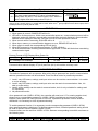
MODEL NAME EXPLANATION
DTC 1
DTC Series
1
Controller
Position
2
3
4
5
DTC: Delta C series Temperature Controller
1: first controller
2: controller in parallel
1
Auxiliary Output 0: standard, 2 groups output, no auxiliary output
1: 1 group auxiliary output. Not available now.
Groups
2: 2 groups auxiliary output. Not available now.
00: standard
3
4 Optional
01: CT input. Not available now.
02: Event input. Not available now.
R: Relay output SPST, 250VAC, 3A
5 Main Output
V: Voltage Pulse output 12V +10﹪~-20﹪
Type
C: Current output 4~20mA
L: Linear Voltage output 0~10V
2
※ Standard: DC24V input, Relay output for 2nd group, RS-485 communication.
3
FUNCTION AND SPECIFICATION
Power Supply
Voltage Range
Power
consumption
DC24V. Isolated switching power
Rated voltage: 90%~110%
Rated 24 Vdc, Max. 24 W combined, 3 W + 3 W x no. of DTC-2000 (max. 7
connected)
Thermocouple: K, J, T, E, N, R, S, B, L, U, TXK
Sensor Type
Platinum RTD: Pt100, JPt100
Linear DC input: 0~5V,0~10V, 0~ 20 m A,4~20 m A, 0~50mV
Sampling Rate Analog input: 0.15 sec. Thermocouple or Platinum RTD: 0.4 sec.
Control Method PID , PID program control, Manual or ON/OFF
Relay output (SPST), Max. load 250VAC, 3A resistive load
Voltage pulse output: DC 12V, Max. output current 40mA
Output Type
Current output: DC 4 ~ 20m A output (Load resistance: Max. 500Ω)
Analog voltage output: 0~10V (Load resistance shall be higher than 1000Ω)
Control output, Alarm output, or Retransmission output (only for linear voltage
Output Function
and current output as 1st group)
Alarm Function 12 Alarm mode selections
Communication RS-485 digital communication, 2400bps~38400bps.
Communication
Mod-bus communication protocol, support RTU/ASCII.
Protocol
Internal
Provide internal connection terminals to transmit 24V power supply and
Connection
communication signal.
Vibration
10 to 55Hz, 10m/s2 for 10min, each in X, Y and Z directions
Resistance
Shock
Max. 300m/ s2, 3 times in each 3 axes, 6 directions
Resistance
Ambient
0 oC to +50 oC
Temperature
Storage
-20 oC to +65 oC
Temperature
Altitude
2000m or less
Relative Humidity 35% to 85% RH (non-condensing)
Pollution Degree Degree 2
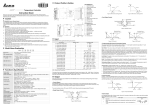
2
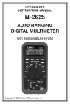
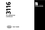
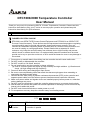
PRODUCT PROFILE AND OUTLINE
3.0
4
6
4
5
7
1
11
8
90.0
12
10
13
2
9
3.4
60.0
3.0
4.0
25.2
3.0
3
3
3
4
5
6
10
7
1
90.0
9
8
2
5
3.4
60.0
3.0
25.2
4.0
2
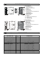
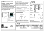
DTC1000R/V/C/L
1. RUN/STOP switch
2. Wiring and Model name
3. DIN fix
4. I/O terminals
5. LED indicators
6. Extension hole of the extension unit
mounting pins
7. Specification label
8. Extension port
9. Extension clip
10. DIN rail
11. RS-485 communication port
12. Extension clip
13. DC power input
DTC2000R/V/C/L
1. Wiring and Model name
2. DIN rail clip
3. I/O terminals
4. LED indicators
5. Extension hole of the extension unit
mounting pins
6. Specification label
7. Extension port
8. Extension clip
9. DIN rail
10. Extension port
INPUT SENSOR TYPE
Input Selection for DTC series:
Input Sensor Type
0~50mV Linear Voltage Input
4~20mA Linear Current Input
0~20mA Linear Current Input
0~10V Linear Voltage Input
0~5V Linear Voltage Input
Platinum RTD (Pt100)
Platinum RTD (JPt100)
Thermocouple TXK type
Thermocouple U type
Thermocouple L type
Thermocouple B type
Thermocouple S type
Thermocouple R type
Thermocouple N type
Thermocouple E type
Thermocouple T type
Thermocouple J type
Thermocouple K type
Register
Value
17
16
15
14
13
12
11
10
9
8
7
6
5
4
3
2
1
0
Available Range
0~50mV
4~20mA
0~20mA
0~10V
0~5V
o
-200 ~ 600 C (-328~1112oF)
-20~ 400 oC (-4~752 oF)
-200~800 oC (-328~1472oF)
-200~500 oC (-328~932oF)
-200~850 oC (-328~1562oF)
100 ~ 1800 oC (212~3272oF)
0 ~ 1700 oC (32~3092oF)
0 ~ 1700 oC (32~3092oF)
-200 ~ 1300 oC (-328~2372oF)
0 ~ 600 oC (32~1112oF)
-200 ~ 400 oC (-328~752oF)
-100 ~ 1200 oC (-148~2192oF)
-200 ~ 1300 oC (-328~2372oF)
3
Note 1: an external 250Ω precision resistor is needed for current input.
Note 2: factory setting: PT100 input. It is adjustable for linear input and feedback ranges. The default range of
input feedbadk is –999~9999. For example, when a 0~20mA analog input is selected as the input
temperature sensor type, -999 indicates 0mA and 9999 indicates 20mA. If change the input range to
0 ~ 2000, then 0 indicates 0mA and 2000 indicates 20mA. One display scale is equal to 0.01mA.
6
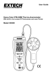
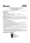
OUTPUT FUNCTION
Output control for DTC is selective: Control output (heating, cooling), Alarm output, or
Retransmission output.
Control Output:
Temperature can individually be controlled by two groups outputs: cooling (forward) or heating
(reverse). When Dual Loop output control is used, two output controls shall be designed for cooling
(forward) or heating (reverse). If two control outputs with the same direction are performed, only 1st
group control period is valid. Control methods: PID control, ON/OFF control, Manual control, and
PID program control.
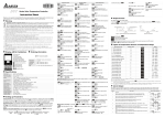
Single-output Control:
Heating Hysteresis
Cooling Hysteresis
ON
Heating
OFF
Cooling
PV
Set Point
Set Point
Figure1: ON-OFF control of single output
Output
Output
100%
100%
Cooling
Heating
PV
0
PV
0
Set Point
Figure 2: PID Control,
forward (cooling) control
Set Point
Figure 3: PID Control,
reverse (heating) control
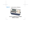
Dual Output Control:
Dead band
Heating hysteresis
Cooling hysteresis
ON
Heating
Cooling
OFF
PV
Set point
Figure 4. ON-OFF control
of dual loop output
4
Output
Heating
Dead band:dead
band width:positive
Output
Cooling
Heating
PV
0
Dead band:dead
band width:negative
Cooling
0
Set Point
Figure 5: PID control,
Dead band is positive
PV
Set Point
Figure 6: PID control,
Dead band is negative
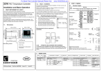
Description of Function and Parameters Setting:
PID program control by 8 patterns (Pattern No. 0~7) is supported in DTB series. Each pattern
contains 8 steps (step No. 0 ~ 7), one Link Pattern parameter, one Cycle parameter and one
Actual Step parameter
Start Pattern:
is in operation mode and it is used to set the Start Pattern of PID program
control (This parameter appear in
mode only).
Steps: Include set point X and execution time T, these two parameters setting. The set point (SV)
should reach temperature X after the period of execution time T. If the set point is the same as the
result of the previous setting, then it is called Soak program control. If not, then it is called Ramp
program control. Therefore, PID program control is also called Ramp/Soak program control.
The default of step No. 0 in this controller is Soak program control. The controller will control the
temperature (PV) to reach the set point X and then keep the temperature at set point X. The period
of execution time is time T which provided by step No. 0.
Link Pattern Parameter: For example, when set
to 2, it indicates that pattern No. 2 will
execute next after the execution of pattern No. 0. If set to
, it indicates the program will stop
after executing the current pattern and the temperature will keep at the set point of the last step.
Cycle Parameter: Additional execution cycle number. For example, when set
to 2, it
indicates that pattern No. 4 should execute twice in addition. Include origin one time execution,
total execute three times.
Actual Step Parameter: Execution step number per pattern (can set to 0 ~ 7). For example, when
set
to 2, it indicates that pattern No 7 will not execute other steps than step 0 to step2.
Execution: When
of start pattern.
When
is set to
is set to
, the program will start to execute in order from the step 0
, the program will stop and the control output is disabled.
When
is set to
, the program will stop and the temperature at that time will be
controlled at the set point before program stop. Select
again, then the program will restart
and execute from step 0 of start pattern.
When
is set to
, the program will hold and the temperature at that time will be
controlled at the set point before program hold. Select
again, then the program will follow
the step before hold and start to execute through the rest of the time.
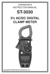
Retransmission Output:
When the 1st group output of this controller is linear voltage or current output, it can be
Retransmission that is the output variation corresponding with input. For example, when read
5
value=0 with input range 0~1000, output will be 0mA or 0V. When read value=1000, output will be
20mA or 10V.
Output
Output
Output slope
is negative
10V or 20mA
0V or 4mA
10V or 20mA
PV
PV Low
Output slope is positive
PV
0V or 4mA
PV High
PV Low
PV High
Figure 7: Retransmission
Alarm Output:
This controller provides twelve types of alarm input selections. When PV is higher or lower than SV,
alarm output will act. Following table consists of twelve alarm output modes.
SV
Alarm Type
Alarm Output Function
0 No Alarm Function
Output is OFF
Deviation upper- and lower-limit:
ON
This alarm output operates when PV value is higher than the
OFF
1
setting value SV+(AL-H) or lower than the setting value
AL-H
AL-L SV
SV-(AL-L).
ON
Deviation upper-limit:
OFF
2 This alarm output operates when PV value is higher than the
SV
AL-H
setting value SV+(AL-H).
ON
Deviation lower-limit:
OFF
3 This alarm output operates when PV value is lower than the
AL-L SV
setting value SV-(AL-L).
ON
Reverse deviation upper- and lower-limit:
OFF
4 This alarm output operates when PV value is in the range of
AL-H
the setting value SV+(AL-H) and the setting value SV-(AL-L).
AL-L SV
ON
Absolute value upper- and lower-limit:
OFF
5 This alarm output operates when PV value is higher than the
AL-H
setting value AL-H or lower than the setting value AL-L.
AL-L
ON
Absolute value upper-limit:
OFF
6 This alarm output operates when PV value is higher than the
AL-H
setting value AL-H.
ON
Absolute value lower-limit:
OFF
7 This alarm output operates when PV value is lower than the
AL-L
setting value AL-L.
Deviation upper- and lower-limit with standby sequence:
ON
This alarm output operates when PV value reaches set point
OFF
8
(SV value) and the value is higher than the setting value
AL-H
AL-L SV
SV+(AL-H) or lower than the setting value SV-(AL-L).
Deviation upper-limit with standby sequence:
ON
This alarm output operates when PV value reaches set point
OFF
9
(SV value) and the reached value is higher than the setting
SV
AL-H
value SV+(AL-H).
Deviation lower-limit with standby sequence:
ON
This alarm output operates when PV value reaches the set
OFF
10
point (SV value) and the reached value is lower than the
AL-L SV
setting value SV-(AL-L).
ON
Hysteresis upper-limit alarm output:
OFF
11 This alarm output operates if PV value is higher than the
setting value SV+(AL-H). This alarm output is OFF when PV
AL-L AL-H
6
SV
Alarm Type
value is lower than the setting value SV+(AL-L).
Hysteresis lower-limit alarm output:
This alarm output operates if PV value is lower than the
12
setting value SV-(AL-H). This alarm output is OFF when PV
value is higher than the setting value SV-(AL-L).
Alarm Output Function
ON
OFF
AL-H AL-L
st
Attention: AL-H and AL-L include AL1H, AL2H and AL1L, AL2L. When the 1 group output is set to alarm
output, AL1H (1024H) and AL1L (1025H) will be used. When the 2nd group output is set to alarm output, AL2H
(1026H) and AL2L (1027H) will be used.
7
LED DISPLAY
1. When power is normal, POWER LED will be lit.
2. LED will be lit after power on. Within one second after power on, communication protocol will be
displayed; and at the following second after communication protocol displayed, communication
address will be displayed. After that, LED will all be lit to show operation is normal.
3. When control action is executing, RUN LED will be lit.
4. When input, memory, or communication happens to error, ERROR LED will be lit.
5. When output is acted, the corresponding LED will be lit.
6. When PID program is auto adjusting parameter, AT LED will blink.
7. RX LED will blink when receiving communication signal and TX LED will blink when transmitting
communication signal.
Protocol Format of LED Display When Power On
AT
TX
RX
O1
000:2400bps 001:4800bps 010:9600bps
Parity 00:None
011:19200bps 100:38400bps
10: Odd
O2
Err
Run
01:Even 0: ASCII 0:2 Stop bit
1: RTU 1:1 Stop bit
Communication address display: AT (bit 6) and Run (bit 0) will combine to binary code.
8
PASSWORD FUNCTION
The default of password will not operate. After writing 4-byte password into specific communication
address, password function will be activated. There are three levels for password protection:
1. Level1: only LED status, settings, and input values can be read via communication. It is unable
to revise anything.
2. Level2: only LED status, settings, and input value can be read via communication. Also, it is
able to revise setting.
3. Level3: all the settings can be read via communication, but it is only revisable for settings and
AT adjustment.
4. No password function.
Once password is set (106EH~1070H), the controller will enter level 1. For entering another level,
please key in corresponding password in 106BH~106DH (see Address and content of Data
Register). After power off, it will get back to level one. If password protection function shall be
dismissed, it is necessary to clear all password setting.
To enable password function, it is necessary to write corresponding password (106EH~1070H)
when password status is dismissed. To dismiss password levels, intended password setting should
be write in specific function address 106EH~1070H.
Password status can be read from 106EH~1070H. Statuses corresponding to each bit are shown as
the following table:
Bit
Status
b0
Level 1
b1
Level 2
b2
b3
b4
b5
Level 3 Level 1 locked Level 2 locked Level 3 locked
7
b6
Unlock
Bit=0 means no password setting. Bit=1 means password is set (b0~b2). b3~b6 are used for
displaying current password status.
9
SYNCHRONOUS COMMUNICATION PROTOCOL & AUTO NUMBER ID FUNCTION
By using Auto Number ID function, the communication protocol of DTC2000 can be set the same as
the one of DTC1000. ID numbers tend to increase.
1. Set the auto communication flag to be “1” for DTC1000 (communication address 1022H).
2. Switch off the controller before connecting to another DTC2000. After that, switch on the power
again.
3. Communication default: 9600bps, 7bits, Even, 1 stop bit.
4. This function will result in additional 3~5 seconds for power on.
10
RS-485 COMMUNICATION
1.
2.
3.
4.
Supporting transmission speed: 2400, 4800, 9600, 19200, 38400bps.
Non-supported formats: 7, N, 1 or 8, E, 2 or 8, O, 2.
Communication protocol: Modbus (ASCII or RTU)
Function code: 03H to read the content of register (max. 8 words). 06H to write one word into
register. 01H to read bits data (max. 16 bits). 05H to write one bit to register.
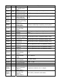
5. Address and Content of Data Register:
Address
Setting
1000H
Content
Process value (PV)
1001H
0
1002H
6000
1003H
-200
1004H
12
1005H
0
1007H
4
1008H
4
1009H
476
100AH
100BH
100CH
260
41
0
100DH
0
100EH
100
Set point (SV)
Upper-limit of
temperature range
Lower-limit of
temperature range
Input temperature
sensor type
Control method
1st group of
Heating/Cooling
control cycle
2nd group of
Heating/Cooling
control cycle
PB Proportional
band
Ti Integral time
Td Derivative time
Integration default
Proportional control
offset error value,
when Ti = 0
COEF setting when
Explanation
Temperature unit: 0.1 degree. Analog input: 1EU.
Following read values happen to errors:
8002H : Initial process (Temperature value is not got yet)
8003H : Temperature sensor is not connected
8004H : Temperature sensor input error
8006H : Cannot get temperature value, ADC input error
8007H : Memory read/write error
Unit: 0.1 degree. Analog input: 1EU.
Upper-limit ban, unit: 0.1 degree.
Lower-limit ban, unit: 0.1 degree.
Please refer to the contents of the “Temperature
Sensor Type and Temperature Range” for detail
0: PID, 1:ON/OFF, 2: manual tuning, 3:PID program
control
0~99, 0:0.5 sec
0~99, 0:0.5 sec (it will be invalid when both groups are
control output at the same time)
1 ~ 9999, unit: 0.1 degree, analog input: 1EU
0~9999
0~9999
0~1000, unit: 0.1%
0~1000, unit: 0.1%
1 ~ 9999, unit: 0.01
8
Address
Setting
100FH
0
1010H
0
1011H
0
1012H
0
1013H
0
1014H
0
1015H
0
1016H
0
1020H
0
1021H
0
1022H
0
1024H
40
1025H
40
1026H
40
1027H
40
102AH
102CH
0
102EH
102FH
1030H
1032H
1033H
1034H
0
Content
Explanation
Dual Loop output
control are used
Dead band setting
-999~9999, unit: 0.1 degree or 1EU
when Dual Loop
output control are
used
Hysteresis setting
0~9999, unit: 0.1 degree or 1EU
value of the 1st
output group
Hysteresis setting
0~9999, unit: 0.1 degree or 1EU
value of the 2nd
output group
Output value read
Unit: 0.1%, write is valid only under manual control
and write of Output 1 mode
Output value read
Unit: 0.1%, write is valid only under manual control
and write of Output 2 mode
Upper-limit regulation 1 scale=2.8μA=1.3mV
of analog linear
output
Lower-limit regulation 1 scale=2.8μA=1.3mV
of analog linear
output
Temperature
-999~+999, unit: 0.1 degree or 1EU
regulation value
Alarm 1 type
Please see the contents of the “Alarm Outputs” for
detail
Alarm 2 type
Please see the contents of the “Alarm Outputs” for
detail
Auto-setting
Auto setting ban of communication: 0, auto setting of
communication flag communication: 1
Upper-limit alarm 1 Please see the contents of the “Alarm Outputs” for
AL1H
detail
Lower-limit alarm 1 Please see the contents of the “Alarm Outputs” for
AL1L
detail
Upper-limit alarm 2 Please see the contents of the “Alarm Outputs” for
AL2H
detail
Lower-limit alarm 2 Please see the contents of the “Alarm Outputs” for
AL2L
detail
Read/Write status
b1:ALM2, b2:℃, b3:℉, b4: ALM1, b5: O2, b6:O1, b7:
AT
Setting of
0: positive, 1: negative
positive/negative
proportional output
LED status
b0: RUN,b1: ERR, b2: O2,b3: O1,b4: RX,b5:TX b6: AT
Software version
V1.00 indicates 0x100
Start pattern
0~7
number
Remaining time of
Unit: second
read execution
Remaining time of
Unit: minute
reading execution
step
Step number of
0~7
reading current
execution step
9
Address
Setting
1035H
1037H
1000
1038H
0
1040H~
1043H
7
1050H~
1053H
0
1060H~
1063H
0
1068H
1
1069H
0
106AH
0
106BH
0
106CH
0
106DH
0
106EH
0
106FH
0
1070H
0
1071H
1
1072H
0
1073H
2
1074H
1
1075H
1076H
1
1
2000H~
203FH
0
2080H~
20BFH
0
Content
Executing number
of reading current
pattern
Upper-limit of
proportional output
Lower-limit of
proportional output
Actual step number
setting inside the
correspond pattern
Cycle number of
repeating executing
pattern 0~7
Link pattern number
setting of the
current pattern
Control
execution/Stop
setting
Output 1: control
selection
Output2: control
selection
Dismiss level 1
Read/write allowed
Dismiss level 2.
Use level 3.
Dismiss level 3.
Use level 2
Dismiss level 1/Set
password
Dismiss level 2/Set
password
Dismiss level 3/Set
password
Read/Write
communication
address
Read/Write
communication
format
Baud rate setting of
communication
Data length setting
of communication
Parity bit setting
Stop bit setting
Pattern 0~7 to set
target temperature
Pattern 0:
2000H~2007H
Pattern 0~7 to set
execution time.
Pattern 0:
2080H~2087H
Explanation
0~7
0~100% max. analog output is upper limit, unit: 0.1%
0~100% max. analog output is lower limit, unit: 0.1%
0~7 = N means the pattern is executed from step from
0 to N.
0~199 means the pattern is executed for 1~200 times.
0~8, 8 means program end. 0~7 means the next
execution number after completing current pattern.
0: Stop, 1: execute, 2: program end, 3: program hold
0: heating, 1: cooling, 2: alarming, 3: proportional
output
0: heating, 1: cooling, 2: alarming
Shall be same as level 1 password setting (106E)
Shall be same as level 2 password setting (106F)
Shall be same as level 3 password setting (1070)
Clear old password before new password setting
Clear old password before new password setting
Clear old password before new password setting
1~247
RTU:1, ASCII:0
0~4: 2400~38400
0: 8bit
1: 7bit
0: None 1:Even 2: Odd
0: 2 stop bit 1: 1stop bit
Temperature measure unit: 0.1 degree
Time 0~900 (1 minute for each scale)
10
6. Address and Content of Bit Register: ( First bit of reading will put into LSB, Write data = FF00H
for bit set, 0000H for bit data as “0”)
0811H
0813H
0814H
0815H
0816H
0: oF, 1: oC (default)
AT setting OFF: 0 (default), AT setting ON: 1
0: STOP, 1: Execute (default)
1: Program temporary stop
1: Program stop
Temperature unit display selection
AT setting
Control RUN/STOP setting
Program hold flag
Program stop flag
7. Communication format:01: read bit data, 05: write bit data, 03: read word, 06: write word.
ASCII Mode:
To Read Instruction
Starting word
Machine
address 1
Machine
address 0
Instruction 1
Instruction 0
’:’ ’:’
‘1’
‘1’
‘0’
‘0’
‘3’
‘1’
‘0’ Response data
length (byte)
‘8’
‘1’
‘0’ Data content of
‘0’ 1000H/081xH
‘0’
‘0’
‘9’
‘D’ Data content of
1001H
‘0’
‘4’
‘0’
‘1’
‘F’
‘4’
‘0’
‘0’
‘0’
‘0’
‘2’
‘1’
‘7’
‘0’
‘1’
‘D’
‘0’
‘1’
‘1’
‘0’
‘0’
‘3’
‘1’
Ending word 1 CR CR
Ending word 0 LF
’:’ ’:’
‘0’
‘0’
‘A’
Starting word
To Write Instruction
‘0’
‘0’
‘1’
To read
‘0’
data/Staring
‘0’
word address
‘0’
‘0’
To read data
length/Word
‘0’
length
‘0’
(word/bit)
‘2’
LRC1 check ‘E’
LRC 0 check
To Read Response
Message
LF
Machine
address 1
Machine
address 0
Instruction 1
Instruction 0
Starting
word
Machine
address 1
Machine
address 0
Instruction 1
Instruction 0
’:’ ’:’
LRC 0
‘1’
‘1’
‘0’
‘0’
‘6’
‘5’
‘0’
To write
‘8’
data
‘1’
address
‘0’
‘F’
To write
‘F’
‘0’ data content
‘0’
‘E’
LRC1
‘1’
‘0’
‘0’
‘1’
‘0’
‘3’
‘E’
‘8’
‘F’
‘0’
‘8’
‘1’
‘0’
‘F’
‘F’
‘0’
‘0’
‘E’
‘3’
‘D’
‘3’
‘1’
‘1’
‘0’
‘0’
‘6’
‘5’
‘D’
’:’ ’:’
‘0’
‘0’
‘1’
‘0’
‘0’
‘1’
‘0’
To write
‘3’
data content ‘E’
‘8’
LRC1
‘F’
Starting
word
Machine
address 1
Machine
address 0
‘0’
‘0’
To write
data
address
To Write Response
Message
Instruction 1
Instruction 0
LRC 0
LRC1 check
‘0’ ‘E’ Ending word CR CR Ending word CR CR
1
1
LRC 0 check ‘3’ ‘4’ Ending word LF LF Ending word LF LF
0
0
Ending word 1 CR CR
Ending word 0
LF LF
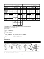
LRC Check:
LRC check is the added sum from “Machine Address” to “Data content”. For example, 01H + 03H +
10H+ 00H + 00H + 02H = 16H, then take the complementary of 2 to get EA.
RTU Mode:
11
To Read Instruction
To Read Response
Message
Machine
address
01H 01H
Machine
address
Instruction
Starting
address of
reading
data
To read
data length
(word/bit)
CRC low
byte
03H 02H
10H 08H
Instruction
To Write Instruction
01H 01H
Machine
address
01H 01H
To Write Response
Message
Machine
address
01H 01H
03H 02H Instruction 06H 05H Instruction 06H 05H
10H 08H
10H 08H
Response
To write
To write
00H 10H data length 04H 02H
01H 10H
01H 10H
data
data
(byte)
address
address
00H 00H
01H 17H
Data content
02H 09H
F4H 01H
1
C0H BBH
CRC high CBH A9H
byte
03H
Data content
2
20H
To write
data
content
CRC low
byte
CRC high
byte
CRC low
byte
BBH 77H
CRC high
byte
15H 88H
03H FFH
20H 00H
DDH 8FH
To write
data
content
CRC low
byte
E2H 9FH CRC high
byte
03H FFH
20H 00H
DDH 8FH
E2H 9FH
Following is a CRC (Cyclical Redundancy Check) program example:
unsigned int reg_crc = 0xffff; i = 0;
while (length--)
{
reg_crc ^= RTUData[i];
i ++;
for (j = 0; j < 8; j++)
{
if (reg_crc & 0x01)
reg_crc = (reg_crc >> 1) ^ 0xA001;
else
reg_crc = reg_crc >> 1;
}
}
return(reg_crc);
11
INSTALLATION
DTC modules can be expanded up to 8, and installed with DIN rail mounting
Delta Electronics, Inc. 31-1 Shien Pan Road, Kuei San Industrial Park, Taoyuan Shien 33341, Taiwan, R.O.C.
TEL: 886-3-362-6301 FAX: 886-3-362-7267
12