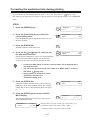
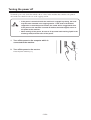
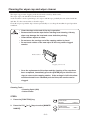
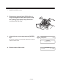
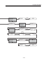
1
OPERATION MANUAL
MIMAKI ENGINEERING CO., LTD.
TKB Gotenyama Building, 5-9-41, Kitashinagawa, Shinagawa-ku, Tokyo 141-0001, Japan
Phone: +81-3-5420-8671 Fax: +81-3-5420-8687
URL: http: // www.mimaki. co. jp /
D201264
E-mail: [email protected]
DISCLAIMER OF WARRANTY
THIS LIMITED WARRANTY OF MIMAKI SHALL BE THE SOLE AND EXCLUSIVE
WARRANTY AND IS IN LIEU OF ALL OTHER WARRANTIES, EXPRESS OR IMPLIED, INCLUDING, BUT NOT LIMITED TO, ANY IMPLIED WARRANTY OF
MERCHANTABILITY OR FITNESS, AND MIMAKI NEITHER ASSUMES NOR AUTHORIZES DEALER TO ASSUME FOR IT ANY OTHER OBLIGATION OR LIABILITY OR MAKE ANY OTHER WARRANTY OR MAKE ANY OTHER WARRANTY IN
CONNECTION WITH ANY PRODUCT WITHOUT MIMAKIÅfS PRIOR WRITTEN
CONSENT. IN NO EVENT SHALL MIMAKI BE LIABLE FOR SPECIAL, INCIDENTAL OR CONSEQUENTIAL DAMAGES OR FOR LOSS OF PROFITS OF DEALER
OR CUSTOMERS OF ANY PRODUCT.
Requests
• This Manual has been carefully prepared for your easy understanding, however, please do not hesitate to contact a distributor in your district if you have
any inquiry.
• Description contained in this Manual are subject to change without notice for
improvement.
• Generally, names and designations referred to in this Manual are trade marks
or registered trade marks of the manufacturers or suppliers.
Reproduction of this manual is strictly prohibited.
Copyright © 2005 MIMAKI ENGINEERING Co., Ltd. All Rights Reserved.
FCC Statement (USA)
This equipment has been tested and found to comply with the limits for a Class A digital
device, pursuant to Part 15 of the FCC Rules. These limits are designed to provide reasonable protection against harmful interference when the equipment is operated in a commercial environment. This equipment generates, uses and can radiate radio frequency energy
and, if not installed and used in accordance with the instruction manual, may cause harmful
interference to radio communications.
Operation of this equipment in a residential area is likely to cause harmful interference in
which cause the user will be required to correct the interference at his own expense.
• In the case where MIMAKI-recommended cable is not used for
connection of this device, limits provided by FCC rules can
be exceeded. To prevent this, use of MIMAKI-recommended
cable is essential for the connection of this device.
INTERFERENCE TO TELEVISIONS AND RADIOS
The product covered by this Instruction Manual produces low radio waves while it is in
operation. The product can interfere with radios and televisions if set up or commissioned
under improper conditions. The product is not guaranteed against any damage to specificpurpose radio and televisions.
The product’s interference with your radio or television will be checked by turning on/off
the power switch of the product.
In the event that the product is the cause of interference, try to eliminate it by taking one of
the following corrective measures or taking some of them in combination.
• Change the direction of the receiving antenna or the feeder of your
radio/television.
• Change the installing direction of the product.
• Move the receiver away from the product.
• Use a power line for the receiver that is not shared with the product.
LASER SAFETY
This Model is certified as a Class I laser product under the U.S. Department of Health and
Human Services Radiation Performance standard according to the Radiation Control for
Health and Safety Act of 1968. This means that this Model does not produce hazardous
laser radiation.
CDRH REGULATION
The Center for Devices and Radiological Health for the U.S. Food and Drug Administration
Implement regulations for laser products. The Label shown below indicates compliance
with the CDRH regulations and is labeled on the product when marketed in the United
States. This Model is equivalent to Class I laser device according to CDRH Regulation.
This product complies with 21 CFR chapter I and subchapter J.
Foreword
Congratulations on your purchase of a Garment Printer “GP-1810D”.
GP-1810D allows the original discharge liquid to print directly cloths and take some color off with
4-color original ink.
Read this Operation Manual carefully and make the most effective use of your printer.
• [GP-1810D] shifts by a high-speed head. To avoid danger of injury or
damage, be sure to read this Operation Manual carefully before starting to operate it.
On This Operation Manual
• This Operation Manual describes the operation and maintenance of Garment Printer
GP-1810D (hereinafter referred to as the machine).
• Please read and fully understand this Operation Manual before putting the machine into
service. It is also necessary to keep this Operation Manual on hand.
• Make arrangements to deliver this Operation Manual to the person in charge of the
operation of this machine.
• This Operation Manual has been carefully prepared for your easy understanding, however, please do not hesitate to contact a distributor in your district or our office if you
have any inquiry.
• Description contained in this Operation Manual are subject to change without notice for
improvement.
• In the case where this Operation Manual should be illegible due to destruction by fire or
breakage, purchase another copy of the Operation Manual from our office.
-i-
TABLE OF CONTENTS
Foreword .................................................................................................. i
On This Operation Manual ............................................................... i
Features .................................................................................................. vi
Safety precautions during installation ................................................... viii
Safety symbols used in manual ................................................... viii
Example of pictorials within the manual ....................................... viii
Never do the following ................................................................... ix
Precautions in use .......................................................................... x
Precautions in installation ............................................................. xii
How to read this operation manual ....................................................... xiii
Display on the LCD and Indication of the Keys............................ xiii
Structure of this Operation Manual .............................................. xiv
CHAPTER 1 Before Use
Where to install the machine ................................................................ 1.2
Moving the machine ............................................................................. 1.3
Configuration and function ................................................................... 1.4
The Front ....................................................................................
The Rear .....................................................................................
Operation Panel ..........................................................................
Capping station ...........................................................................
Carriage ......................................................................................
1.4
1.5
1.6
1.8
1.9
Ink cartridge and Ink station ............................................................... 1.10
Precautions in handling the ink cartridge ................................... 1.10
Ink station ................................................................................... 1.11
Types of work that can be used ......................................................... 1.12
Sizes of work that can be used ................................................. 1.12
Precautions in handling the work .............................................. 1.12
Direct printing on a cloth .................................................................... 1.13
MENU mode ...................................................................................... 1.14
CHAPTER 2 Basic Operations
Operation ............................................................................................. 2.2
Switching on the power supply ............................................................ 2.3
Turning the power on ................................................................... 2.3
Filling of discharge liquid at the time of starting works ......................... 2.4
Station cover ........................................................................................ 2.6
Opening/closing the station cover ............................................... 2.6
Adjusting the head height .................................................................... 2.7
- ii -
Setting the work on the machine .......................................................... 2.8
Fixing the work holder ................................................................. 2.9
Establishing the origin and the print area ........................................... 2.10
Initial value ................................................................................. 2.10
Changing the origin and the print area ....................................... 2.11
Checking and solving nozzle clogging ............................................... 2.12
Correcting the work feed rate ............................................................. 2.15
Correcting the media feed rate during printing ................................... 2.17
Printing an image from source data ................................................... 2.18
Starting the printing operation ................................................... 2.18
Interrupting the printing operation ............................................. 2.19
Displaying machine information ......................................................... 2.20
To replenish ink, set a new ink cartridge in the ink station ................. 2.21
Filling of the washing liquid at the end of the works ........................... 2.22
Turning the power off ......................................................................... 2.24
CHAPTER 3 Daily Care
Routine maintenance ........................................................................... 3.2
When the machine is left unused for a long period of time ......... 3.2
Precautions during cleaning ........................................................ 3.2
Maintenance for frame components ............................................ 3.3
Washing ink from the slider surface ............................................ 3.3
Filling of the washing liquid at the end of the works ............................. 3.4
Cleaning the wiper cap and wiper cleaner ........................................... 3.6
Cleaning the nozzle [Nozzle Cleaning] ................................................ 3.9
Replacing the flushing tray ink absorber ............................................ 3.12
When the waste ink tank becomes full ............................................... 3.14
Ink discharge way cleaning [Drain Wash] .......................................... 3.15
When not in use the machine over the long term [Storage Wash] ..... 3.17
CHAPTER 4 How to Set Functions
Basic operations of menus ................................................................... 4.2
Function mode ..................................................................................... 4.4
Registering a type ....................................................................... 4.4
Changing the type ....................................................................... 4.4
Setup functions .................................................................................... 4.5
Change the display language [DISPLAY] ............................................. 4.8
- iii -
CHAPTER 5 Maintenance
Maintenance of the machine ................................................................ 5.2
Setting the maintenance function................................................ 5.2
Maintenance setup functions ...................................................... 5.3
Printing setup conditions [LIST] ........................................................... 5.4
Printing HEX CODE [DATA DUMP] ...................................................... 5.5
When medium thickness is changed [Print Adjust] .............................. 5.6
Cleaning the station interior [Station]-[Carriage Out] ........................... 5.8
When the message [Replace Wiper] is displayed [Station]-[Wiper Exchng] ..... 5.9
Fill up the ink [Ink Filling] ................................................................... 5.11
Set up the ink of different type [Ink Change] ...................................... 5.12
Displaying the firmware version [INFORMATION] ............................. 5.15
Execute the flushing and cleaning regularly [Routine Control] .......... 5.16
Specifying the print head line [Use Head] .......................................... 5.18
CHAPTER 6 When Abnormal Conditions Are Encountered
Abnormal conditions where no error massage appears ...................... 6.2
The machine cannot be energized .............................................. 6.2
The machine cannot perform printing ......................................... 6.2
If image quality declines ....................................................................... 6.3
While lines/thin spots are obvious or dark stripes occur (In the direction of travel of the head) ............................................................ 6.3
Characters fluctuate doubly or triply into paper feed .................. 6.3
Displacement is observed between outward and inward printing 6.3
The respective color ink injected by the respective color heads do
not properly overlap .................................................................... 6.3
Large ink drop on medium .......................................................... 6.3
Become lighter during the printing and then printing without ink 6.3
When printing trouble occurs in ........................................................... 6.4
Unable to discharge .................................................................... 6.4
Impaired discharge function ........................................................ 6.4
Some strip streaks occur on the image with narrow print width .. 6.4
Problems where error messages are given on the LCD ...................... 6.5
Errors accompanied by warnings ................................................ 6.5
Error messages ........................................................................... 6.8
- iv -
APPENDIX
Basic specifications .............................................................................. A.2
Ink specification ................................................................................... A.4
Discharge liquid / Washing liquid specification .................................... A.5
Consumable items ............................................................................... A.5
Location of safety labels ...................................................................... A.6
Other labels .......................................................................................... A.8
Function flowchart ................................................................................ A.9
-v-
Features
The features of the machine are described below. Together with the method of operation of the
machine explained in this manual, they help you understand how to use the machine properly.
Use a discharge liquid
Print the original discharge liquid directly on T shirt, and perform heat treatment to take off some
colors. Also, discharge composition printing is available.
• Only the dyed cotton by a reactive dye ink allows for discharging. According to reactive dye
inks, its effects are all different.
Use the pigment ink for textile
The new pigment ink for textile allows for printing directly T shirt.
It allows for the heat treatment (simple post treatment) without media preparation. It is kind to the
skin and remains breathable and absorbent.
High-Speed printing
New piezo electric heads, the staggered-layout print head provides more attractive, faster printing,
and allows ultra high-precisions 6-head 1-way printing.
High-precision printing and high-quality images
The machine is capable of printing high-quality images with a maximum resolution of 720 dpi.
Head height adjustable to 50mm maximum
Can print on T-shirts and other materials placed around a board.
Prints on extra wide work of 1870mm maximum
Up to 1870mm wide work can be set for printing over up to a1860mm wide area.
Indication of the INK Remains
Since the amount of ink that remains can be checked even during operation of the machine, you can
use the ink and medium without waste.
- vi -
Features
High-speed interface
The "IEEE-1394" interface allows for high-speed data reception from the computer.
Easy “origin” setting
The cross-shaped LED pointer allows easy visual setting.
Prevents the head and work collision
When the work is too thick or the head height is set too low, the head protective sensor senses the
head height and avoids the head collision accordingly.
- vii -
Safety precautions during installation
Safety symbols used in manual
Safety signal words
Pictorial signs are used in this Operation Manual for safe operation of and in prevention of damages
to the machine. Pictorial signs and their meanings are given below. Read and fully understand
before reading the text.
• Indicates a potentially hazardous condition which, if not avoided,
could result in serious injury or death. Be sure to read this manual for
proper operation.
• Indicates a potentially hazardous condition which, if not avoided,
could result in moderate or minor injury or property damage.
• The symbol "
" indicates helpful information that will facilitate the
use of the machine.
• Indicates the reference page for related contents.
Example of pictorials within the manual
• The symbol " " indicates the case where some phenomenon that
requires a CAUTION sign (including "DANGER" and "WARNING"
signs) exists. A concrete precaution (precaution against an electric
shock in the case of the sketch given on the left) is shown in the illustration.
• The symbol " " indicates a prohibited behavior. A concrete illustration of prohibition (disassembly is prohibited in the sketch given on
the left) is shown in or next to the illustration.
• The symbol " " indicates a thing that is forced to be done and instruction that is forced to be followed. A concrete illustration of instruction
(the removal of a plug from the receptacle is instructed in the sketch
given on the left) is drawn in the illustration.
- viii -
Safety precautions during installation
Never do the following
WARNING
Do not disassemble or modify the machine.
•
Power supply and voltage
Never disassemble or remodel
the main unit of the machine and
•
the ink cartridge. Disassembling/
remodeling any of them will
•
result in electric shocks or
breakdown of the machine.
Be sure to use the machine with
the power supply specifications
indicated.
Be sure to connect the plug of
the power cable to a grounded
receptacle. If not, fire or electric
shocks can result.
Do not use the machine in damp places.
•
Avoid damp environments when
putting the machine into service.
Do not splash water onto the
machine.
Handling of ink cartridges
•
High-humidity or water will give
rise to fire, electric shocks or
ink tank in a place that is out of
the reach of children.
breakdown of the device.
•
If the machine is used under an
immediately rinse off with water
and consult a medical doctor.
abnormal condition where the
machine produces smoke or
unpleasant smell, fire or electric
shocks can result. Be sure to
Laser sensor
turn off the power switch immediately and detach the plug from
•
This device is equivalent to Class
I laser device according to CDRH
the receptacle. Check first to be
sure that the machine no longer
Regulation. LASER CAUTION
Label for CDRH regulation shown
produces smoke, and contact a
distributor in your district for
below is provided with the device.
Also, the device is equivalent to a
repair. Never repair your machine by yourself since it is very
Class I laser device according to
JIS/IEC standard. The label ac-
dangerous for you to do so.
cording to these standards shown
below is provided with the device.
To avoid causing pain in your eyes
or visual impairment, do not review
Handling of the power cable
•
•
If ink settles on the skin or
clothes, immediately wash it off
with detergent or water.
If you get ink in your eyes,
Abnormal event occurs.
•
Store ink cartridges and waste
Use the supplied power cable.
Take care not to damage, break
the laser beam through a lens or
the other optical observation sys-
or work on the power cable.
If a heavy matter is placed on
tem.
the power cable, heated or
drawn, the power cable can
break to cause fire or electric
shocks.
- ix -
Precautions in use
CAUTION
Periodic exchange parts
•
Front cover and lever
There are some parts which
•
must be replaced by service
engineer. You have to make a
the cover or lever will abort
printing.
contract with distributors or
dealers for after-sale service.
•
A head for the discharge liquid
is consumable. Please ex-
Never open the front cover and/
or lever during printing. Opening
Keep the machine level
•
change a new one in half a year
when using it everyday.
Adjust the level feet to keep the
machine level at all times.
Warning labels
Protection against dust
•
•
It is strongly recommended to
warning label. Be sure understand firmly the warnings given
use the device in a room that
is not dusty. Set the Refresh
on the labels. In the case where
any of the warning label has
level 2 or 3 when in bad
environment.
(
•
become so soiled that the
warning message is illegible or
has come off, purchase a new
page 4.6)
Keep the front cover to be
closed also when the machine
one from your local distributor or
our office.
is not engaged in printing. If
not, dust can accumulate on
•
Refer to Appendix for the label
adhering locations.
the head nozzle.
When leaving the workshop
after the working hours, be
sure to take off any medium
from the roll hanger. If any
medium is left on the roll
•
hanger, dust can put on it.
Store medium in a bag. Wiping
off dust accumulated on a
medium will adversely affect
the medium due to static
electricity.
•
•
Frequently clean the capping
station to eliminate dust and
paper chips.
Dust in the head will also
cause drops of ink to fall on
the media during printing. If
this phenomenon takes place,
be sure to clean up the head.
(
This machine is adhered with a
page 3.6)
-x-
Safety precautions during installation
CAUTION
•
Ink cartridges
•
•
•
•
If the ink cartridge is moved from
a cold place to a warm place, do
exclusive one can cause a
trouble. Remover that the user
not use for three hours.
Open the ink cartridge just
shall be charged for a repair cost
to correct any damage resulting
before installing it in the machine. If it is opened and not
from the use of ink other than the
exclusive type.
installed for a long time, the
machine may not plot normally.
•
Make sure to store ink cartridges
in a cold and dark place.
•
The ink cartridge cannot be
refilled.
Neither pound the ink cartridge
nor shake it violently so as to
prevent leakage of ink.
Be sure to thoroughly consume
the ink in the ink cartridge, once
it is opened, within three months.
If an extended period of time has
•
Do not touch or stain the contacts
of the ink cartridge as doing so
may cause damage to the print
circuit board.
passed away after opening the
cartridge tank, printing quality
•
Using any ink type other than the
would be poor.
Do not discharge printing for
baby clothes as some of formaldehyde remains on a fabric after
post treatment by heat press.
Wash out any cloths at least one
time to remove residual formaldehyde after post treatment by
heat press.
- xi -
Precautions in installation
CAUTION
A place exposed to direct sunlight
A place that is not horizontal
•
•
Do not install machine where it is
exposed to direct sunlight or
Do not place the machine where
the machine cannnot be installed on a level surface,or you
may not secure the stabilized
work may be discolored.
plot work.
A place in which temperature and humidity vary
by a great margin
•
A place that vibrates
Use the machine under the
following environment.
•
Do not install the machine
where it is subject to vibratiion
or you may not secure the
stabilized plot work.
Operating environment:
15 to 30°C
40 to 65% (Rh)
A place full of dust or cigarette smoke
•
A place exposed to direct air blowing from air
conditioner, etc.
•
Do not install the machine
where it is exposed to significant
Do not install the machine that is
dust or cigarette smoke, or the
dust may adheres to the ma-
directly exposed to blowing air
from an air conditioner, etc, or
chine and cause the ink drops to
deflect.
you may get spattered with the
ink.
How to read this operation manual
Display on the LCD and Indication of the Keys
In this Operation Manual, the characters displayed on the LCD of the operation panel and the keys
used to operate the machine are explained, together with the operation procedure.
page 1.6.
Operate the machine while confirming the display on the LCD.
Display on the LCD
The content of display is shown in characters in a
box as shown at right.
Operate the machine according to the explanation
of the operation procedure and the content of display on the LCD.
In this Operation Manual, each setting and messages displayed on the LCD is enclosed in [ ], like
[Type1], [Please Wait], etc.
Operation keys
In the text of this Operation Manual, the operation
keys are shown enclosed in brackets.
[ ] and [ ] indicate JOG keys.
The other operation keys are enclosed in brackets,
as [FUNCTION].
FUNCTION
SETUP
< ENT >
SETUP
SELECT
: Type 1
Structure of this Operation Manual
This manual consists of the following six chapters to describe the handling of the machine.
Chapter 1 Before Use
This chapter describes the name and function of each section of the machine as well as ink and work.
Chapter 2 Basic Operations
This chapter describes a series of operations and settings, ranging from
power-on to end of printing.
Chapter 3 Daily Care
This chapter describes the daily cleaning.
Chapter 4 How to Set Functions
This chapter describes the setting function.
Chapter 5 Maintenance Functions
This chapter describes functions intended to correct adverse influences on
picture quality and to check abnormal conditions as well as the procedure
to be taken to replace a used wiper.
Chapter 6
When Abnormal Conditions Are Encountered
This chapter describes how to correct troubles after the occurrence of an
abnormal condition on the machine.
Appendix
This appendix describes the specifications of the machine, function menu
structure and introduces separately-available consumables.
- xiv -
CHAPTER 1
Before Use
This chapter describes the name and function of each section of the machine as well
as ink and work.
Table of contents
Where to install the machine ................................................................ 1.2
Moving the machine ............................................................................. 1.3
Configuration and function ................................................................... 1.4
Ink cartridge and Ink station ............................................................... 1.10
Types of work that can be used ......................................................... 1.12
Direct printing on a cloth .................................................................... 1.13
MENU mode ...................................................................................... 1.14
- 1.1 -
Where to install the machine
Secure a suitable installation space before assembling the machine.
Install the machine considering enough space for the machine size and to perform print operation.
Model
Width
Depth
Height
Gross weight
GP-1810D
3070 mm
2210 mm
1350 mm
620 kg or less
1000 mm
or more
1000 mm
or more
1000 mm or more
5100 mm
- 1.2 -
4300 mm
1000 mm or more
Moving the machine
This section explains to carry the machine to e.g., an instruction location after assembled.
Raise the level feet of the table frame before moving the machine to a new location.
• Be sure to disconnect the power cable and the interface cable before
moving the machine.
• When moving the machine, take care not to apply excessive shock to
it.
• Be sure to adjust the level feet to level the machine at the new location.
Method of moving the machine
When moving the machine, it must be held up
by at least eight persons as illustrated at right.
Locking the caster
Raise the level feet of the table frame before
moving the machine to a new location.
Lower and adjust the level feet to level the
machine at the new location.
•
Use a level gauge to ensure that the table is
level in the front and in the back.
- 1.3 -
Configuration and function
The Front
3
1
2
3
4
5
6
7
8
11
9
10
Name
Function
1
Pilot lamp
Displays the plotter status as ACTIVE (green), or ERROR (red).
2
Station Cover
A cover for the station maintenance. Open the cover when performing
the station maintenance.
3
EMERGENCY Switch
(Emergency) Stop printing.
4
Parallel connector
Bi-directional parallel interface connector. (complies with IEEE1284)
5
IEEE1394 connector
A 400 M bps interface connector compatible with -IEEE1394.
6
AC inlet
The power cable is connected to the AC inlet.
7
Power switch
It turns on/off the power to the machine.
8
Operation panel
This panel has the operation keys required for operating the machine
and the LCD for displaying set items, etc. (
page 1.6)
9
Waste ink tank
Waste ink gathers in this tank. (
page 3.14)
10
Table frame
It supports the main unit. It is provided with casters and level foots for
moving the machine.
11
Table
Moves back and forth when performing printing.
- 1.4 -
Configuration and function
The Rear
1
2
1
2
Name
Function
1
Ink cartridge
Each cartridge contains ink of a specific color.
2
Ink station
Set the ink cartridges specified.
- 1.5 -
Operation Panel
The operation panel that is used to operate the machine.
Display
Displays a set item, a guidance error, etc.
POWER lamp
It lights up (in green) when the
power to the machine is turned on.
XY keys
[ ][ ][ ][ ]
They are used to shift the
carriage and the medium under the LOCAL mode. In addition they are used to select a set value.
(
Z key
Adjust the head (Y bar) height.
XY
Z
page 2.7)
[VIEW] key
page 1.7)
[CYCLE START] key
(
VIEW
CYCLE START
Used to attach and detach the work.
The carriage retracts and the table
moves forward. (
Perform copy printing.
page 2.8)
[TEST] key
[DATA CLEAR] key
Plots the test pattern for
checking Nozzle cogging.
Erase the data has been received.
(
(
page 2.19)
page 2.13)
[FUNCTION] key
Enter to the setting function
[REMOTE] key
menu. (
Change the operation mode between
the REMOTE mode and the LOCAL
page 4.2)
mode. (
[END] key
Used to cancel the last set item
that has been input or to return
to the previous setting menu.
page 1.14)
[CLEANING] key
Performs head cleaning when ink
[ENTER] key
clogging occurs. (
Used to move to the lower-level menu
and establish the settings.
- 1.6 -
page 2.13)
Configuration and function
Functions of the XY keys
Each of the keys varies in function according to the time at which it is used.
When setting a
plotting origin / plotting area
When selecting a function
When inputting a choice
selected among several
alternatives
Shifts the carriage to the left.
Shifts the carriage to the right.
Shifts the work (table) away from
you.
Restores the last previous
function.
Selects the next value.
Moves the work (table) toward you.
Moves to the next function.
Selects the last previous value.
Functions of the Z keys
Press the Z keys to move the head (Y bar) height. (
- 1.7 -
page 2.7)
Capping station
The capping station consists of ink caps, wipers for cleaning the heads, etc.
Cap
Wiper
: It covers the nozzle so as to prevent the head nozzle from drying up.
: It is used to clean the head nozzle.
The wipers are consumable parts. If the wiper is deformed or the work is stained,
page 5.9)
replace the wiper with a new one. (
The wiper cleaner takes off the discharged ink remains on of the wiper to keep affection
of the discharge liquid to the head, at a minimum. Clean the wiper cleaner regularly.
(
page 3.6)
Wiper
Wiper cleaner
Ink Cap
Flushing Tray
- 1.8 -
Configuration and function
Carriage
The cartridge provides the changeover valve of the ink head for print and discharge, and the
changeover valve for the discharge liquid and the cleaning liquid for the ink head.
It provides a LED pointer which specifies a starting position to print.
Discharge liquid / washing liquid
changeover valve
Carriage
- 1.9 -
Ink cartridge and Ink station
Precautions in handling the ink cartridge
• Use the specified ink.
Using any ink type other than the exclusive one can cause a trouble.
Remember that the user shall be charged for a repair to correct any
damage resulting from the use of ink other than the exclusive type.
• If ink settles on the skin or clothes, immediately wash it off with soap
and water.
If you get ink in your eyes, immediately wash your eyes with a lot of
clean water. Then, consult a doctor as soon as possible.
• Do not shake the ink cartridge violently. Shaking or turning it roughly
can cause leakage of ink.
• Never disassemble the ink cartridge.
• The ink cartridge cannot be refilled. Refilling the ink cartridge can
cause a trouble. Remember that MIMAKI assumes no responsibility
for any damage caused by the use of the ink cartridge replenished with
ink.
• Be sure to store ink cartridges in a cold and dark place.
• If the ink cartridge is moved from a cold place to a warm place, leave it
in the room temperature for three hours or more before using it.
• Be sure to thoroughly consume the ink in the ink cartridge, once it is
opened, within six months. If an extended period of time has passed
after opening the cartridge tank, plotting quality would be poor.
• Be sure to store ink cartridges in a cold and dark place.
• Store ink cartridges in a place that is out of the reach of children.
• Request an industrial waste processor for processing of empty cartridges.
• Do not touch or stain the contacts of the ink cartridge as doing so may
cause damage to the print circuit board.
• Do not discharge printing for baby clothes as some of formaldehyde
remains on a fabric after post treatment by heat press. Wash out any
cloths at least one time to remove residual formaldehyde after post
treatment by heat press.
- 1.10 -
Ink cartridge and Ink station
Ink station
The Discharge liquid / Washing liquid station supplies ink to the 2 front row of Carriage.
The 4-colors ink station supplies ink to the 2 rear row of Carriage.
Remember these relationship when checking the heads for clogged nozzles, replacing ink cartridge
and replenishing inks.
K: Black ink
M: Magenta ink
C: Cyan ink
Y: Yellow ink
D: Discharge liquid
W: Washing liquid
- 1.11 -
Types of work that can be used
The following describes the sizes of work that can be used and the method of handling.
Sizes of work that can be used
Maximum
1870 mm
Minimum
Max. printing width
1050 mm
1860 mm *1
Max. printing length
Thickness
1010 mm
50 mm or less
Weight
60kg or less when load is evenly distributed
*1:
When the mode is Discharge Composition printing mode at 720 x 720 variable,
and the product serial number is E1509013 or before, maximum printing width is
1,100 mm.)
Precautions in handling the work
Carefully observe the following when handling the work.
• Work thickness
When setting the work used, adjust the head height.
Otherwise, the work and/or the head can be damaged.
• Expansion and contraction of the work
Do not use sheet types of work immediately after unpacking.
The work can expand and contract due to room temperature and humidity.
The work have to be left in the atmosphere in which they are to be used for
30 minutes or more after unpacked.
• Warps of work
If you want to use board-shaped works, always use flat boards.
• Other tips
• The device has a moving table. The work must be fixed to the table
during operation. If necessary, fix the work with a tape.
• Maintain a sufficient head gap when printing on a fluffy material. If the
print head nozzle is allowed to touch the fluff, it may be blocked and
affect the print quality.
- 1.12 -
Direct printing on a cloth
• To minimize color variations, maintain constant humidity and temperature while printing directly on a cloth.
1. When using the Pigment ink for textile (TPig ink)
•
•
No special preparation is necessary. Print on a dry cloth.
Print twice to ensure higher color fastness.
•
The post-treatment condition varies by the material of the heating process.
Determine the optimum condition carefully.
REFERENCE
Press
T-shirt material
160oC / 60 second
Cotton broad cloth
190OC / 40 second
2. When using the dye ink
•
Pre-treatment and post-treatment of the cloth are necessary according to the
acid dye ink (silk, nylon, etc.), reactive dye ink (cotton, etc.) or disperse dye
ink (polyester, etc.).
•
Refer to the Ink guidance.
The machine can print on a wide variety of cloths and color stability, fastness
and tones can vary significantly by pre-treatment in particular. Use your own
judgment in deciding pretreatment and post-treatment and introduce changes
as deemed necessary.
3. When using the discharge liquid (discharge ink)
•
After discharge printing, perform post treatment (heat press) immediately. If
it takes some time after discharge printing and some water is dried off, it may
reduce the effectiveness of discharging.
•
Please perform post treatment within 5 minutes after discharge printing.
Set out the optimal condition according to status of use after discharge
process.
Reference: heat press 150 for 60 seconds
•
Some unreacted discharge liquid still remains in fabric after discharge printing and press heat. Those remaining liquid may cause turning into slight
yellow.
- 1.13 -
MENU mode
The unit’s four modes are described blow.
< LOCAL > mode
This mode is for the preparatory state.
All keys are effective to enable setups.
The machine is able to receive data from computer, however, it will not perform printing.
In this mode, it is possible to perform the following operations.
1. Pressing the appropriate XY keys to set up an origin and the printing area.
1. Pressing the Z keys to set up the print head (Y bar).
2. Pressing the [TEST] key to start test printing.
2. Pressing the [CLEANING] key to start cleaning the print head.
3. Pressing the [DATA CLEAR] key to erase the printing data the machine has received.
4. Pressing the [FUNCTION] key to set plotting conditions.
5. Pressing the [VIEW] key brings the work to the detaching position.
< REMOTE > mode
The machine prints an image from data it receives.
During the printing operation, press the [REMOTE] key to interrupt the printing operation.
While the machine is in the LOCAL mode, press the [REMOTE] key to put the machine into the
REMOTE mode.
< CYCLE START > mode
This mode may be used in combination with “Raster Link Pro” to repeat printing using the identical
data (copy). “Raster Link Pro” has a copy function which eliminates the need to send data from the
computer for every printing.
While the machine is in the LOCAL mode, press the [CYCLE START] key to put the machine into
the CYCLE START mode.
< FUNCTION > mode
While the machine is in the LOCAL mode, press the [FUNCTION] key to put the machine into the
FUNCTION mode.
This is the mode in which printing conditions can be set.
- 1.14 -
CHAPTER 2
Basic Operations
This chapter describes a series of operations and settings, ranging from power-on to
end of printing.
Table of contents
Operation ....................................................................................................... 2.2
Switching on the power supply ...................................................................... 2.3
Filling of discharge liquid at the time of starting works .................................. 2.4
Station cover ................................................................................................. 2.6
Adjusting the head height .............................................................................. 2.7
Setting the work on the machine ................................................................... 2.8
Establishing the origin and the print area .................................................... 2.10
Checking and solving nozzle clogging ........................................................ 2.12
Correcting the work feed rate ...................................................................... 2.15
Correcting the media feed rate during printing ............................................ 2.17
Printing an image from source data ............................................................ 2.18
Displaying machine information .................................................................. 2.20
To replenish ink, set a new ink cartridge in the ink station .......................... 2.21
Filling of the washing liquid at the end of the works .................................... 2.22
Turning the power off ................................................................................... 2.24
- 2.1 -
Operation
The following shows a series of operations and settings, ranging from power-on to end of printing.
For details on each item, refer to the reference page.
Turn on the power on
P. 2.3
Filling of the discharge liquid
P. 2.4
Check the head height
P. 2.7
Set the work
P. 2.8
Set the origin and printing area
P. 2.10
Print the test pattern
P. 2.12
Correct the work feed rate
P. 2.15
Start the printing
P. 2.18
Washing of the discharge head
P. 2.22
Turn off the power
P. 2.24
- 2.2 -
Switching on the power supply
Turning the power on
1. Turn on the power to the computer which is
connected to the machine.
2. Turn on the power to the machine.
Press the power switch to “ I ”.
• Make sure that the station cover is closed.
If it is open, initialization is not performed.
• Leave 10 seconds and more intervals before
turning on the power after once turning off.
BOOT
When the power is switched on, the LCD first displays
“BOOT” and then displays the firmware version number.
GP-1810D
3. The message [Please Wait] appears flushing
on the LCD.
V∗.∗∗
Please Wait
The initial operation of the machine is performed.
• To avoid injuries, keep your hands away
from the machine while in motion.
<< LOCAL >>
X =1010
Y = 1860
4. The machine enters the LOCAL mode.
Display the print area.
•
•
The Local mode is not available until ink initialization is completed. Install the
ink cartridges. (Refer to page 24 of the setup guide.)
The following message will appear when the ink cartridges are not installed:
Ink Cartridge
12345678ABCDEFGH
- 2.3 -
Filling of discharge liquid at the time of starting works
If the discharge liquid in this machine has used in the long period, it may cause the decrease in the
print head life. In order to prevent the shortening of the life of the head for discharge liquid, the
discharge liquid contained is replaced by washing liquid when it is not used for an extended period
of time. At the time of starting works, the washing liquid filled in the head for discharge liquid is to
be drained and the discharge liquid is filled in.
STEPS:
1. At the LOCAL state, press the
[FUNCTION] key 4 times.
FUNCTION
DCG/WASH SW
<ENT>
2. Press the [ENTER] key.
3. Use up/down key to select
[Discharge].
DCG/WASH SWITCH
Fill
: Discharge
4. Press the [ENTER] key.
5. Open the station cover.
6. Turn the all valves to [DCG].
SW Valve To [DCG]
Press [ENT] key
7. Close the station cover.
8. Press the [ENTER] key.
9. Fill up the discharge liquid after
initializing this machine.
10.
Initialize
Please Wait
It indicates the remaining
run-time.
Filling
00:00:00
- 2.4 -
Filling of discharge liquid at the time of starting works
11.
Filling of the discharge liquid is
completed, menu returns to the
LOCAL mode.
•
•
<< LOCAL >>
X =1010
Y = 1860
Every day at the time of starting works, the filling of the discharge liquid
shall be performed.
Every day at the time of finishing works, the filling of the washing liquid shall
be performed for the protection of head for discharge liquid. (
- 2.5 -
page 3.4)
Station cover
Opening/closing the station cover
•
Keep the station cover closed during printing operation. Opening the station
cover during printing interrupts image printing and disables continuous
processing.
If you open the station cover during printing, the carriage will stop for safety, resulting in abortion of
printing. In this case, re-start the machine and computer following the procedure described below.
STEPS:
1. When opening the station cover during printing, the message shown on the right will be
displayed.
Check Stop SW or
Station Cover
Stop the printing.
2. Stop the data transmission from the computer.
3. Close the station cover.
PRESS < ENT > KEY
4. Press the [ENTER] key.
Please Wait
5. The carriage will start to move.
The carriage will carry out a series of performance same as
that taken after turning on the power to the machine.
(
page 2.3)
- 2.6 -
Adjusting the head height
The head can be adjusted in height, according to thickness of a work used for printing.
The head height must be set according to the work thickness. If the head height is too low, it may
affect the printing quality and even damage the work or the machine itself. Be sure that the head
height is correct
•
•
Adjust the head height before setting a work on the machine.
Leave at least 3mm clearance when printing on T-shirts or other fluffy materials. Otherwise, the head will touch the fluff and affect the print quality.
•
Confirm the head height setting value, press the [ENTER] key in the LOCAL,
REMOTE and CYCLE mode. (
page 2.20)
STEPS:
1. The machine enters the LOCAL mode.
Press the [REMOTE] key and put the machine back into the
LOCAL mode.
2. Press the Z [ ] or [ ] keys to adjust the head
<< LOCAL >>
X =1010
Y = 1860
Head Height
∗ ∗ . ∗ mm
height.
The ideal head height is equal to the work thickness + 1.0 to
2.0mm. Check the work thickness before adjusting the head
height.
• If the work thickness is not uniform, use the
work thickness at the thickest point.
3. Press the [ENTER] key.
Head Height
∗ ∗ . ∗ mm
4. The machine revert the LOCAL mode.
- 2.7 -
<< LOCAL >>
X =1010
Y = 1860
Setting the work on the machine
Set the work on the table as following.
•
Adjust the head height before placing a work on the machine. ( page 2.7)
•
•
Always print on flat works.
When printing on T-shirts or other cloths, set them flat.
STEPS:
1. Turn on the power to the machine.
<< LOCAL >>
X =1010
Y = 1860
2. Adjust the head height. ( page 2.7)
Head Height
After adjusting, return to the LOCAL mode.
∗ ∗ . ∗ mm
3. Press the [VIEW] key.
VIEW
< ENT >
4. Push the [VIEW] key or the [ENTER] key.
∗ ∗ VIEW ∗ ∗
The table moves toward you.
5. The machine revert the LOCAL mode.
6. Set the work on the marking on the table.
Secure work in such a manner that work can
not float or be dislocated.
- 2.8 -
<< LOCAL >>
X =1010
Y = 1860
Setting the work on the machine
Fixing the work holder
When printing on a material of allowable size (1870 x 1050mm maximum) that tends to bend
upward (floating at two or four edges), use the work holders on any of the four table edges
to fit the work in place.
STEPS:
Work holder
1. Turn (or remove) the knob screws to loosen the
work holder.
A collar is fitted to each of the screws of the
work holder. Do not lose them when they are
removed.
Knob
2. The right and left work holders may be turned
Right and left work holders
(square C-shape)
upside down as needed according to the work
size.
Turn upside down
Front and back work holders
(L-shaped; cannot be turned
upside down)
Work
3. Place the work between the work holder and
the table.
4. While pressing the work holder down, retighten the knob screws.
- 2.9 -
Table
Establishing the origin and the print area
Initial value
The origin and the print area are set as follows by default until they are changed:
Output direction
Work
15mm
15mm
Effective printing area
15mm
Origin
- 2.10 -
Establishing the origin and the print area
Changing the origin and the print area
The default origin and the print area may be changed as needed.
•
When printing on the entire work surface (without margins), the printing
origin and the printing area must be set outside of the work. They must be set
as close to the work as possible, however, to minimize smearing the machine
itself. Otherwise, there will be much ink mists especially when printing on
thick works.
STEPS:
1. The machine enters the LOCAL mode.
<< LOCAL >>
X =1010
Y = 1860
2. Move the carriage to the position at which to
establish an origin by pressing the XY[ ], [ ],
X = 500
[ ] or [ ] keys.
Origin Setup
Y = 970
The origin changes as the carriage moves.
• A cross-shaped point mark appearing on the
table or the work will be the display coordinate.
3. After deciding the origin, press the [ENTER]
Origin Setup
∗ ∗ ∗ ∗ Origin ∗ ∗ ∗ ∗
key.
4. Press the [ENTER] key.
Print Area
Press the [END] key if the print area is to be left unchanged.
5. Set the print area by pressing the XY[ ], [ ],
[ ] or [ ] keys.
end <
> ent
X = 900
Print Area
Y = 1810
X = 900
<< LOCAL >>
Y = 1810
Display the new print area determined by the carriage
movement.
6. After deciding the print area, press the [ENTER] key.
The machine revert the LOCAL mode.
The new print area is displayed.
• The new setting is saved until the origin or the
print area is changed.
• The print area will be set to the initial value if it is
set to the same position as the origin.
- 2.11 -
Checking and solving nozzle clogging
Make test printing to check whether there is nozzle clogging or other printing failures.
If the finished test pattern shows any sign of abnormal conditions, carry out the cleaning function.
•
To perform the test print on a cut sheet medium, use a medium whose size is
A4 or larger with placed in landscape configuration.
•
The discharge liquid is colorless and invisible on paper and fabric. Use attached color paper (in pink).
Test Pattern
1
3
2
5
6
4
7
8
B
A
E
F
Output direction
Normal Pattern
Abnormal Pattern
Nozzle is dirty
Clogged with ink
- 2.12 -
Checking and solving nozzle clogging
STEPS:
1. The machine enters the LOCAL mode.
2. Press the [TEST] key.
<< LOCAL >>
X =1010
Y = 1860
TEST PRINT
< ENT >
3. Select from all head (L1234), ink head (L12 - - ),
or discharge head (L - - 34).
TEST PRINT
Head Line
: L1234
L1234/L12 - -/L - - 34
4. Press the [ENTER] key.
5. Select numbers to print.
TEST PRINT
Print Count
=1
6. Press the [TEST] key or [ENTER] key.
The machine prints the test pattern.
∗ ∗ PRINT∗ ∗
After the test print is done, the table moves to the front and
turns to LOCAL mode.
<< LOCAL >>
X =1010
Y = 1860
7. Check the test patterns.
If a failure occurs, proceed with step 8; otherwise, terminate
the operation.
If a failure occurs, perform the following operation
8. Press the [CLEANING] key.
9. Press the XY [ ] or [ ] keys to select the headblock for cleaning.
(Refer to page.1.11 [Ink station] )
Clean
Select
:12563478
: ABEF- - - -
Clean
Select
:12563478
: ABEF- - - [1256ABEF] / [3478]
10. Press the XY [ ] or [ ] keys to set on/off of the
Clean
Select
blocks that need cleaning.
:12563478
: ABEF- - - On / Off
- 2.13 -
11. Press the [ENTER] key.
12. Press the XY [ ] or [ ] keys to select the type
of cleaning.
Cleaning
Type
: Normal
Normal / Strong
Normal
:
Select this if any line is bent.
(When selecting the Pigment ink for textile
[T Pig], this function is invalid.)
Strong
:
When printing trouble is not solved even with
Normal cleaning.
13. Press the [ENTER] key.
Cleaning
00: ∗ ∗ : ∗ ∗
It displays the remaining run-time.
14. The machine revert the LOCAL mode.
<< LOCAL >>
X =1010
Y = 1860
15. Change the work, or establish the new origin.
16. Repeat steps 2 and 3, and check the result of
the test printing.
Repeat STEPS 2 to 13 until normal printing result is obtained.
• Replace the wiper and the ink cap if inferior printing does not improve after
cleaning operations. (
page 3.6)
• In case the TPig ink and dye ink are mixed, the inferior print image may not be
improved in the cleaning, if the TPig ink is set at the front side of the carriage.
Reset the TPig ink at the back side of the carriage, perform the cleaning
operation again.
- 2.14 -
Correcting the work feed rate
When the work type is changed, the amount of work feed changes.
If the correction value is not appropriate, stripes may occur in the printing disturbing neat printing.
Correction for the work feed rate in online is available. (
page 2.17)
CORRECTING PATTERN
Print two bands.
Adjust the print density so that the boundary of the two bands is printed with an even density,
Setting value : -100 - 100
Output direction
Second band
First band
Correction value is too large
Get between lines
Correction value is too small
Overlap
- 2.15 -
STEPS:
1. The machine enters the LOCAL mode.
<< LOCAL >>
X =1010
Y = 1860
2. Press the [FUNCTION] key.
<< LOCAL >>
X =1010
Y = 1860
3. Press the [ENTER] key.
4. Press the XY [ ] or [ ] keys to select a type.
FUNCTION
SELECT
: TYPE1
TYPE1
Print Mode
< ent >
TYPE1
Media Comp.
< ent >
5. Press the [ENTER ] key.
6. Press the XY [ ] or [ ] keys to select [Feed
Comp.].
7. Press the [ENTER ] key.
8. Press the XY [ ] or [ ] keys to enter the printing width.
TYPE1
Print
9. Press the [ENTER ] key.
: Y = 100
∗ ∗ Printing ∗ ∗
Please Wait
Output the pattern.
10. Check the patterns.
Enter a correction value from the output pattern.
TYPE1
Adjust
=0
TYPE1
Print
: Y = 100
• When [ADJUST] is changed to 30, the pattern
moves by about 0.1 mm. Determine the
correction value referencing this amount of
movement.
11. Press the [ENTER ] key.
Register the correction value.
Repeat steps 8 to 11 until normal printing result is obtained.
12. Press the [END] key three times, and the menu
returns to the LOCAL mode.
- 2.16 -
<< LOCAL >>
X =1010
Y = 1860
Correcting the media feed rate during printing
To perform this operation during LOCAL mode, refer to the “Feed Correct”(
page 2.16).
The following describes the procedures to alter the media feed rate during printing or in a REMOTE
mode.
STEPS:
1. Press the [REMOTE] key.
2. Press the [FUNCTION] key to confirm the
current setting value.
< REMOTE >
X= ∗ ∗ ∗ ∗
TYPE∗
Y= ∗ ∗ ∗ ∗
Feed Comp.
Adjust
-50
: ent
Feed Comp.
Adjust
-50
= 100
Press the [END] key when an appropriate value is set or to
abort the operation.
3. Press the [ENTER] key.
Available to alter the medium feed rate.
4. Press the XY [ ] or [ ] keys as needed to set
the amount of correction.
Setting value is available from -100 to +100. Press the [END]
key to return to the REMOTE display. The altered value
ceases to be in effect, and returns to the previous value.
•
•
•
A new value takes effect in real time. The best effect can be obtained while
checking the result.
The unit of the correction value is the same as in “Media Comp.” in the LOCAL mode. (
page 2.16)
Setting value is to be Reset as follow,
*Perform the Feed Correct.
*Perform the Setup reset
5. Press the [ENTER] key.
Confirm the medium feed rate before saving it. Press the
Feed Comp.
Save
100
: ent
< REMOTE >
X= ∗ ∗ ∗ ∗
TYPE∗
Y= ∗ ∗ ∗ ∗
[END] key to return to the REMOTE display. The changed
setting value is to be in effect performing till the next power
on.
6. Press the [ENTER] key to return to the REMOTE display.
The changed setting value is saved. The value is to be in
effect performing till Reset.
< REMOTE >
X=1010
TYPE +
Y=1860
Displays the feed correct value type on drawing. (+/-)
[+] displays if the feed correct value is plus.
[-] displays if the feed correct value is minus.
- 2.17 -
Printing an image from source data
Starting the printing operation
The following describes the method of printing.
For various function settings necessary for printing, refer to “CHAPTER4 How to Set Functions”.
STEPS:
1. The machine enters the LOCAL mode.
2. Press the [REMOTE] key.
<< LOCAL >>
X =1010
Y = 1860
< REMOTE >
X=1010
The machine enters the REMOTE mode.
3. Transmit data from the computer.
The plotting conditions that have been set for the data are
TYPE ∗
Y=1860
< REMOTE >
360 x 360 / 4P / U
displayed.
For the method of data transmission, see the manual for the
output software.
•
When performing Discharge Composition drawing (when Discharge Composition for RIP software is available) and if “V720 x 720” is displayed for the
resolution, the range for Y drawing limits to 1,100 mm. Even if the data exceeds 1,100 mm is send, drawing will be performed up to 1,100 mm.
< REMOTE >
X=1010
TYPE1 +
Y=1860
Displays the in-use setup type.
Displays the feed correct value type on drawing. (+/-)
[+] displays if the feed correct value is plus.
[-] displays if the feed correct value is minus.
The range for Y drawing (measure mm)
The range for X drawing (measure mm)
Display them alternately
< REMOTE >
V360x360
STD / 4P / U / ∗ ∗ . ∗
Print Mode
V: Variable 1, 2
N: Normal 1, 2
Resolution
360x360, 360x540,
360x720, 720x720 (DPI)
Head height
Print Direction
(measure mm)
U, B (U=Unidirectional, B=Bidirectional)
Dividing method 2P, 3P, 4P, 6P, 8P, 12P, 16P
2H, 3H, 4H, 6H, 8H, 12H, 16H
Print quality
(P:pass H: High speed print)
STD: Standard
FINE: Quality of image priority
FAST: Quality of speed priority
HOST: setting up drawing at the computer
- 2.18 -
Printing an image from source data
4. During the printing.
<< LOCAL >>
X =1010
Y = 1860
5. After the printing operation is completed, put
the machine back into the LOCAL mode.
The table will move toward you when printing in the Cycle
Start mode.
• The origin and the print area remain unchanged after printing. You must reset them
page 2.11)
if they need to be changed. (
Interrupting the printing operation
To interrupt the printing operation, stop the carriage and erase (the receive data) from the machine.
STEPS:
1. Press the [REMOTE] key to stop the printing
operation.
<< LOCAL >>
X =1010
Y = 1860
2. If data is being transmitted from the computer
to the machine, stop the data transmission.
DATA CLEAR
3. Press the [DATA CLEAR] key.
< ENT >
The data that has been received is erased.
4. Press the [DATA CLEAR] key or [ENTER] key.
The machine enters the LOCAL mode.
•
<< LOCAL >>
X =1010
Y = 1860
The green pilot lamp indicates that there is no data in the machine.
- 2.19 -
Displaying machine information
Displays the firmware version, ink level etc. This following describes the procedures to display the
machine in formation during printing or REMOTE and CYCLE mode.
• In LOCAL mode, information displays by pressing [ENTER] key as well.
STEPS:
1. Display the LOCAL mode.
<< LOCAL >>
X =1010
Y = 1860
2. Press the [REMOTE] key.
<REMOTE>
X=1010
The machine enters the REMOTE mode.
3. Press the [ENTER] key to display the ink remains.
Y=1860
Ink Level
3231798745990253
Head Height
4. Press the [ENTER] key to display the head
height.
∗ . ∗ mm
Ink Type
5. Press the [ENTER] key to display the ink type.
Type
:TPig
6. Press the [ENTER] key to display the firmware
Ver1.00
version and command.
7. The [ENTER] key displays setting status.
The [ ] key displays the in-use setup contents.
8. The [ENTER] key displays error information
guidance.
MRL-lIC
SETUP < TYPE ∗>
Display [ ] Key
Error Info
Display [ ] Key
The [ ] key displays current warning.
9. Press the [END] key, the machine returns to the
REMOTE or CYCLE mode.
• Return to the REMOTE mode or CYCLE mode
automatically when the 60 seconds pass over
or error is occurred.
- 2.20 -
<REMOTE>
X=1010
TYPE ∗
Y=1860
To replenish ink, set a new ink cartridge in the ink station
If ink in the cartridge comes to an empty, the corresponding message appears.
Printing can be continued but ink may run out during printing.
Immediately put a new ink cartridge.
< When the amount of ink becomes small during printing >
Indicate the ink color which has run out.
The display at right indicates that [slot1] and [slotA] comes to an end.
Ink Near End
1 - - - - - - - A - - - - - - -
< When the amount of ink completely runs out during printing >
Indicate the ink color which has completely run out.
The display at right indicates that [slotC] runs out.
STEPS:
1. Either of the messages shown above is displayed on the LCD during printing.
When [INKnearEND] appears, the local mode is resumed
and the operation stopped each time printing of a single data
is completed. Proceed with Step 2 at the end of the printing
operation. Proceed to Step 2 at the end of the printing
operation.
When [INKEND] appears, printing cannot be continued.
2. Install a new ink cartridge.
Pull out the ink cartridge of the indicated number and then
set a new ink cartridge.
3. The machine enters the LOCAL mode.
Continuous printing is possible.
- 2.21 -
Ink End
- - - - - - - - - - C - - - - -
Filling of the washing liquid at the end of the works
If you leave the head for discharge liquid with discharge liquid filled in for a long time, the life of
the head for discharge liquid will be shortened because the discharge liquid melts the water-shedding
part. To prevent the reduction of its life, at the end of daily operation drain the discharge liquid and
fill in the washing liquid.
STEPS:
1. At the LOCAL state, press the
[FUNCTION] key 4 times.
FUNCTION
DCG/WASH SW
<ENT>
2. Press the [ENTER] key.
3. Use up/down key to select
[Washing].
DCG/WASH SWITCH
Fill
: Washing
4. Press the [ENTER] key.
5. Open the station cover.
6. Turn the all valves to [WASH].
SW Valve To [WASH]
Press [ENT] key
7. Close the station cover.
8. Press the [ENTER] key.
9. Fill up the washing liquid after
initializing this machine.
Initialize
Please Wait
10. It displays the remaining
run-time.
Filling
00:00:00
- 2.22 -
Filling of the cleaning liquid at the end of the works
11.
Filling of the washing liquid is
<< LOCAL >>
X =1010
Y = 1860
completed, menu returns to the
LOCAL mode.
•
•
Every day at the time of finishing works, the filling of the washing liquid shall
be performed for the protection of head for the discharge liquid.
Every day at the time of starting works, the filling of the discharge liquid shall
be performed. (
page 2.4)
- 2.23 -
Turning the power off
To turn the power off, check first whether there is data in the machine that remains to be printed.
Also make sure that the head rests at the capping station.
•
•
If the power is turned off while the machine is engaged in printing, the head
may fail to be retracted in the capping station. If the head is left without
capped for an extended period of time, the nozzle will be clogged with dust.
If the power to the machine is turned off without the head capped, return on
the power to the machine.
When turning off the power, be sure to fill up some head washing liquid in the
discharge head, and then turn off the power.
1. Turn off the power to the computer which is
connected to the machine.
2. Turn off the power to the machine.
Press the power switch to [ O ].
- 2.24 -
CHAPTER 3
Daily Care
This chapter describes daily cleaning.
Table of contents
Routine maintenance ........................................................................... 3.2
Filling of the washing liquid at the end of the works ............................. 3.4
Cleaning the wiper cap and wiper cleaner ........................................... 3.6
Cleaning the nozzle [Nozzle Cleaning] ................................................ 3.9
Replacing the flushing tray ink absorber ............................................ 3.12
When the waste ink tank becomes full ............................................... 3.14
Ink discharge way cleaning [Drain Wash] .......................................... 3.15
When not in use the machine over the long term [Storage Wash] ..... 3.17
- 3.1 -
Routine maintenance
Be sure to conduct maintenance works for the machine when necessary or periodically so as to use
the device for a long time while keeping its printing accuracy.
When the machine is left unused for a long period of time
• Be sure to turn off the power of machine. (
page 2.24)
• Remove the work which setting on the table.
Precautions during cleaning
• Never disassemble the machine. Disassembling the machine can
result in electric shock hazards and breakage of the machine.
• To prevent electric shock hazard and damage to the machine, do not
allow moisture to get inside.
• Turn off power and detach power cable before doing any maintenance.
• Benzine, thinner and chemical agents containing abrasives.
Such materials can deteriorate or deform the surface of the cover.
• Do not apply lubricating oil or the like inside the machine. Such materials can cause the printer mechanism to fail.
• Especially when printing to untreated fabric without preparation by TP
ink, it may cause adherence of cotton waste, dirt, and dust around the
nozzle or the station cap. With some dust around the nozzle and the
wiper, it may cause some trouble on cleaning. Clean the head nozzle,
station cap, and wiper every time when the operation is terminated.
- 3.2 -
Routine maintenance
Maintenance for frame components
If the frame components of the machine have become dirty, wipe off frame with soft cloth using
water or neutral detergent diluted with water, squeeze it and wipe the frame components clean.
Clean the table also as dust may cause ink fly-bend or dropping.
Cleaning Tools :
• Neutral detergent
• Soft cloth (quantity)
Washing ink from the slider surface
The ink may gel and collect under the slider after a long use. The ink droplets may grow in
size and smear the work as a result. To prevent this problem, wet the supplied cotton swab in the
cleaning liquid (A29) and use it to remove the ink from under the head in regular intervals.
• Do not use the cotton swab on the head nozzles. The brush may damage the nozzles and cause poor ink delivery.
Cleaning Tools :
• Cleaning liquid (A29)
• Cotton swabs
- 3.3 -
Filling of the washing liquid at the end of the works
If you leave the head for discharge liquid with discharge liquid filled in for a long time, the life of
the head for discharge liquid will be shortened because the discharge liquid melts the water-shedding
part. To prevent the reduction of its life, at the end of daily operation drain the discharge liquid and
fill in the washing liquid.
STEPS:
1. At the LOCAL state, press the
[FUNCTION] key 4 times.
FUNCTION
DCG/WASH SW
<ENT>
2. Press the [ENTER] key.
3. Use up/down key to select
[Washing].
DCG/WASH SWITCH
Fill
: Washing
4. Press the [ENTER] key.
5. Open the station cover.
6. Turn the all valves to [WASH].
SW Valve To [WASH]
Press [ENT] Key
7. Close the station cover.
8. Press the [ENTER] key.
9. Fill up the washing liquid after
initializing this machine.
Initialize
Please Wait
10. It displays the remaining
run-time.
Filling
00:00:00
- 3.4 -
Filling of the cleaning liquid at the end of the works
11. Filling of the washing liquid is
completed, menu returns to the
LOCAL mode.
<< LOCAL >>
X =1010
Y = 1860
• Every day at the time of finishing works, the filling of the washing
liquid shall be performed for the protection of head for the discharge
liquid.
• Every day at the time of starting works, the filling of the discharge
liquid shall be performed. (
page 2.4)
- 3.5 -
Cleaning the wiper cap and wiper cleaner
The wiper cap prevents clogging of the head nozzle caused by dried nozzle.
The wiper wipes out ink adhered to the head nozzle.
As the machine is used to print images, the wipers and ink caps gradually become stained with ink
and dust. Use the cotton swabs to clean the wiper.
Clean the wiper cap and the wiper cleaner periodically so as to keep the machine in good operation
condition.
• Clean the wiper at the end of the day’s operation.
• Remove dust from the wiper before starting head cleaning. A dusty
wiper may damage the head and cause defective printing.
• Clean the two wipers at a time.
• Do not move the carriage out of the capping station by hand.
• Do not touch rubber of the new wiper as this may cause clogged
nozzles.
Rubber surface
Capping station side
• Once the replacement of the wiper and the cleaning of the caps have
been completed, immediately press the [ENTER] key to allow the carriage to return to the capping station. If the carriage is left in the aforementioned state for an extended period of time, the nozzles can be
clogged.
Cleaning Tools :
• Cleaning liquid (A29)
• Cotton swabs
STEPS:
1. Press the [FUNCTION] key.
2. Press the XY [ ] or [ ] keys to select [MAINTENANCE].
- 3.6 -
FUNCTION
SETUP
< ENT >
FUNCTION
MAINTENANCE
< ENT >
Cleaning the wiper cap and wiper cleaner
3. Press the [ENTER] key.
4. Press the XY [ ] or [ ] keys to select [Station].
5. Press the [ENTER] key.
The table moves away from you and the Y-bar moves
MAINTENANCE
List
< ent >
MAINTENANCE
Station
< ent >
Station Maint
Sel
: Carriage Out
upward. The wiper moves toward you and the carriage
moves away from the station.
6. Open the station cover and clean the both
sides of the wiper.
Use a cotton swab soaked with the cleaning
liquid (A29) to clean off ink blots on wiper.
•
If dirt of curl is serious, replace the wiper with a
new one. At the time of replacement, be sure to
terminate the machine operation and follow the
wiper replacement procedure.
7. Clean the wiper guide shaft using a cotton
swab of cloth.
If dirt is hard to remove, use a cotton swab of cloth dampened with water.
•
Extremely dirty wiper guide shaft may cause
operationed failure of the wiper, resulting in error
display.
- 3.7 -
Carriage Out
Completed
: ent
8. Wipe off the ink adhering to the wiper cleaner
with cotton swab.
•
Full attention should be paid to clean the wiper
due to the sharp edges of the wiper cleaner.
9. Wipe off ink or dirt adhered to the rubber of the
cap and the ceiling of the wiper cover using
cotton swab.
•
Clean the area at the end of the day’s operation.
10. Close the station cover, then press the [ENTER] key.
Carriage Out
Completed
: ent
Execute the initial operation.
Initialize
Please Wait
11. Return to the LOCAL mode.
<< LOCAL >>
X =1010
Y = 1860
- 3.8 -
Cleaning the nozzle [Nozzle Cleaning]
Clean up the nozzle as for nozzle clogging.
If nozzle clogging cannot be resolved even after cleaning several times, execute the [Ink Filling]
function. (
page 5.11)
If this error cannot be resolved with these functions, contact the dealer.
• Two colors (two cartridges) per head are used. If the remaining
amount of one ink is extremely greater than another ink's amount, it
may flow into the cartridge which has lesser ink to make their ink-head
even.
Execute the [Ink Filling] function (P.5-11) if the inks are mixed.
• Operate it in the head only with the nozzle clogging.
Cleaning Tools :
• Cleaning liquid bottle kit A29 (SPC-0137 : Option)
• Syringe
STEPS:
1. Press the [FUNCTION] key in the LOCAL mode.
2. Press the XY [ ] or [ ] keys to select [MAINTENANCE].
3. Press the [ENTER] key.
[Station] is displayed.
FUNCTION
SETUP
< ENT >
FUNCTION
MAINTENANCE
< ENT >
MAINTENANCE
List
< ent >
MAINTENANCE
Station
< ent >
4. Press the XY [ ] or [ ] keys to select [Nozzle
Clean].
Station Maint
Sel
: Nozzle Clean
5. Attention about the ink mixing is displayed.
Press the [ENTER] key.
Color May Mix Up
Continue OK?
6. Press the [ENTER] key.
The table moves backward, the Y-bar moves to the top, the
wiper moves forward, and the carriage moves on the table.
- 3.9 -
: ent
7. Open the station cover and clean the both
sides of the wiper.
Use a cotton swab soaked with the cleaning
liquid (A29) to clean off ink blots on wiper.
•
If dirt of curl is serious, replace the wiper with a
new one. At the time of replacement, be sure to
terminate the machine operation and follow the
wiper replacement procedure.
Clean the wiper and press the [ENTER] key.
Wiper Cleaning
Completed
: ent
8. Fill the cap with the cleaning liquid (A29) using
a syringe.
Fill Up Washings
Completed
: ent
Close the station cover, and press the [ENTER]
key.
Fill Up Washings
Completed
: ent
Nozzle Cleaning
Wait Timer
= 1 min
9. Press the XY [ ] or [ ] keys, select the time to
leave. (1-99 minutes: 1 min unit)
Normally set 1 min.
- 3.10 -
Cleaning the nozzle [Nozzle Cleaning]
10. Press the [ENTER] key.
Initialize
Please Wait
The initial operation is performed.
Remaining time is displayed.
Waiting
00 : ∗ ∗ : ∗ ∗
After remaining time is over, execute cleaning.
It displays the remaining cleaning time.
Cleaning
00 : ∗ ∗ : ∗ ∗
11. Cleaning is completed, the menu returns the
LOCAL mode.
- 3.11 -
<< LOCAL >>
X =1010
Y = 1860
Replacing the flushing tray ink absorber
Replace the ink absorber in the flushing tray if it appears to be clogged. Clogged ink absorber may
cause ink mists and smeared head nozzles.
• Check the ink absorber for clogging at the end the day’s operation.
Cleaning Tool :
• Ink absorber (Order No. M-3 )
STEPS:
1. Press the [FUNCTION] key.
2. Press the XY [ ] or [ ] keys to select
[MAINTENANCE].
FUNCTION
SETUP
< ENT >
FUNCTION
MAINTENANCE
< ENT >
MAINTENANCE
List
< ent >
MAINTENANCE
Station
< ent >
Press the [ENTER] key.
3. Press the XY [ ] or [ ] keys to select
[Station].
4. Press the [ENTER] key.
Station Maint
Sel
: Carriage Out
5. Press the [ENTER] key.
The table moves away from you and the Y-bar moves
upward. The wiper moves toward you and the carriage
moves away from the station.
6. Open the station cover.
- 3.12 -
Carriage Out
Completed
:ent
Replacing the flushing tray ink absorber
7. Remove the F-cover upward from the flushing
F-cover upward
tray.
8. Remove the ink absorber.
9. Place a new ink absorber (supplied) on the
Ink absorber
tray.
Place the ink absorber (as folded) at the center.
•
Make certain the ink absorber is placed flat and
touching the tray. Otherwise, it may interfere with
the head nozzles.
10. Place the F-cover from above.
•
Place the F-cover all the way down. A floating
cover may cause trouble.
11. Close the station cover, then press the [ENTER] key.
Carriage Out
Completed
: ent
The initial operation is performed.
12. Return to the LOCAL mode.
<< LOCAL >>
X =1010
Y = 1860
- 3.13 -
When the waste ink tank becomes full
Waste ink used for cleaning the heads will gather in the waste ink tank.
When the message “Near Full” or “Full” appears, immediately replace the tank with a new waste ink
tank.
Waste Ink Tank
Ink Tank Is Full
Waste Ink Tank
Ink Tank Near Full
• Contact your local MIMAKI distributor or call a local MIMAKI office if
you need a spare waste ink tank.
• Prepare a polyethylene tank for emptying waste ink.
• If ink is dripping, wait until it stops dripping.
• Dispose a long-term unused waste ink regardless of its amount.
STEPS:
1. Pull out the tank toward you.
•
When pulling out the waste ink tank, hold the
opening of the waste ink tank with paper and
then slowly pull it out to prevent waste ink from
spattering.
•
Before replacing ink, put paper on the floor to
prevent it from being stained with ink.
2. Dump waste ink into a separate polyethylene
tank.
•
Request an industrial waste processor for
processing of empty cartridges.
3. Put the empty waste ink tank back in the machine.
- 3.14 -
Ink discharge way cleaning [Drain Wash]
The ink discharge way may become clogged by coagulated ink. It must be cleaned at regular intervals to avoid clogging.
Ink discharge way: Tubing between the cap and the waste ink tank
• Do not move the carriage out of the capping station by hand.
Use the appropriate operation key to move the carriage.
Cleaning Tools :
• Cleaning liquid bottle kit A29 (SPC-0137 : Option)
• Syringe
STEPS:
1. Press the [FUNCTION] key once.
2. Press the XY [ ] or [ ] keys to select [MAINTENANCE].
3. Press the [ENTER] key.
[Station] is displayed.
4. Press the [ENTER] key.
FUNCTION
SETUP
< ENT >
FUNCTION
MAINTENANCE
< ENT >
MAINTENANCE
Station
< ent >
Station Maint
Sel
: Carriage Out
[Carriage out] is displayed.
5. Press the XY [ ] or [ ] keys to select [Drain
Wash].
6. Press the [ENTER] key.
The table moves backward, the Y-bar moves to the top, the
wiper moves forward, and the carriage moves on the table.
Dry suction starts in cycles consisting of 10 seconds of
suction followed by 10 seconds of pause.
- 3.15 -
Station Maint
Sel
Drain Wash
Completed
: Drain Wash
: ent
7. Open the station cover.
8. Remove the cleaning liquid (A29) with a syringe. During the suction pause period, drop
the cleaning liquid (A29) until just before it
overflows from the cap.
9. Close the front cover, and press the [ENTER]
key.
Dry suction continues for 30 seconds and then the machine
is put in LOCAL mode.
10. Return to the LOCAL mode.
Drain Wash
Completed
: ent
Initialize
Please Wait
<< LOCAL >>
X =1010
Y = 1860
- 3.16 -
When not in use the machine over the long term [Storage
Wash]
When not in use the machine over a week, perform [Storage Wash] function to clean the head nozzle
and ink discharge way.
After performing the function, store the machine.
•
Two colors (two cartridges) per head are used. If the remaining
amount of one ink is extremely greater than another ink's amount, it
may flow into the cartridge which has lesser ink to make their ink-head
even.
Execute the [Ink Filling] function if the inks are mixed.
Cleaning Tools :
• Cleaning liquid bottle kit A29 (SPC-0137 : Option)
• Syringe
STEPS:
1. Press the [FUNCTION] key once.
2. Press the XY [ ] or [ ] keys to select [MAINTENANCE].
3. Press the [ENTER] key.
[Station] is displayed.
4. Press the XY [ ] or [ ] keys to select [Storage
Wash].
5. Attention about the ink mixing is displayed.
Press the [ENTER] key.
6. Press the [ENTER] key.
The table moves backward, the Y-bar moves to the top, the
wiper moves forward, and the carriage moves on the table.
7. Open the station cover.
- 3.17 -
FUNCTION
SETUP
< ENT >
FUNCTION
MAINTENANCE
< ENT >
MAINTENANCE
Station
< ent >
Station
Sel
: Storage Wash
Color May Mix Up
Continue OK?
: ent
Wiper Cleaning
Completed
: ent
8. Take off the wiper with holding projections at
the tips of wiper.
9. Use a cotton swab soaked with the cleaning
liquid (A29) to clean off ink blots on wiper and
bracket.
•
If dirt of curl is serious, replace the wiper with a
new one. At the time of replacement, be sure to
terminate the machine operation and follow the
wiper replacement procedure.
10. Insert the clean wiper with holding both projections at the tips of wiper.
Press the [ENTER] key.
11. Fill the cap with the cleaning liquid (A29) using
a syringe.
- 3.18 -
Wiper Cleaning
Completed
: ent
Fill Up Washings
Completed
: ent
When not in use the machine over the long term [Storage Wash]
12. Close the station cover, and press the [ENTER]
key.
13. Press the JOG [ ] or [ ] keys, select the time
to leave. (1-99 minutes: 1 min unit)
Fill Up Washings
Completed
: ent
Nozzle Cleaning
Wait Timer
= 1 min
Normally set 1 min.
Initialize
Please Wait
14. Press the [ENTER] key.
The initial operation is performed.
Remaining time is displayed.
Storage Wash
00 : ∗ ∗ : ∗ ∗
After remaining time is over, execute cleaning.
Cleaning
00 : ∗ ∗ : ∗ ∗
Remaining cleaning time is displayed.
After cleaning the nozzles, the Y-bar moves to the top. The
wiper moves toward you and the carriage moves away from
the station.
15. Open the station cover and clean the both
sides of the wiper.
Use a cotton swab soaked with the cleaning
liquid (A29) to clean off ink blots on wiper.
•
If dirt of curl is serious, replace the wiper with a
new one. At the time of replacement, be sure to
terminate the machine operation and follow the
wiper replacement procedure.
Clean the wiper and press the [ENTER] key.
- 3.19 -
Wiper Cleaning
Completed
: ent
16. Fill the cap with the cleaning liquid (A29) using
a syringe.
Drain Wash
Completed
: ent
Drain Wash
Completed
: ent
Dry suction starts in cycles consisting of 10 seconds of
suction followed by 10 seconds of pause.
Repeat the performance of the air aspiration several times to
clean up the ink discharge way.
Perform the operation for the each cap.
17. Close the station cover, and press the [ENTER]
key.
Carrige returns the station to the initial operation performed.
Initialize
Please Wait
18. Return to the LOCAL mode.
<< LOCAL >>
X =1010
Y = 1860
- 3.20 -
CHAPTER 4
How to Set Functions
This chapter describes how to set up the machine.
Table of contents
Basic operations of menus ............................................................................ 4.2
Function mode ............................................................................................... 4.4
Setup functions.............................................................................................. 4.5
Change the display language [DISPLAY] ...................................................... 4.8
- 4.1 -
Basic operations of menus
This section describes how to change over the operation modes and how to operate the menus.
The following gives the key operation flow to invoke menus.
For detailed menu configuration, refer to Appendix.
REMOTE
<< LOCAL >>
X =1010
Y = 1860
FUNCTION
SET UP
< REMOTE >
X =1010
Y = 1860
< ENT >
ENTER
SET UP
SELECT
: TYPE1
ENTER
TYPE1
Print Mode
TYPE1
Quality
< ent >
: STD
^ , v
TYPE1
Quality
: FINE
^ , v
TYPE1
Quality
: HighSPD
ENTER
^ , v
TYPE1
Over print
< ent >
TYPE1
Layer
= 1
^ , v
TYPE1
Layer
= 2
^ , v
SET UP
SELECT
: TYPE2
- 4.2 -
Basic operations of menus
1. Select the LOCAL mode.
Ascertain first that the machine does not perform printing under the REMOTE mode, then press
the [REMOTE] key to enter the LOCAL mode.
2. Select the FUNCTION mode.
Press the [FUNCTION] key, and the machine will enter the FUNCTION mode.
The FUNCTION mode is divided into two: the setup function and maintenance function. Select
either function.
3. Select a type.
There are four types. The FUNCTION mode can be set for each type depending on the media
type used.
4. Select the Function.
Select the function pressing the XY [ ] or [ ] keys.
5. Enter the Function selected.
Press the [ENTER] key.
6. Select a parameter.
Press the XY [ ] or [ ] keys to select a parameter.
7. Enter the specified value.
Press the [ENTER] key.
8. Restore the LOCAL mode.
Press the [END] key several time to restore the LOCAL mode.
- 4.3 -
Function mode
The FUNCTION mode enable to regists 4 types.
If the type has been registered for each medium type, it becomes easy to change plotting conditions
when the medium type is changed.
Registering a type
1. Make sure that the mode is LOCAL mode.
2. Press the [FUNCTION] key.
3. Press the [ENTER] key.
4. Select any of Types 1 through 4 by pressing
the JOG [ ] or [ ] keys.
5. Press the [ENTER] key.
<< LOCAL >>
X =1010
Y = 1860
FUNCTION
SETUP
< ENT >
SETUP
SELECT
: TYPE1
SETUP
SELECT
: TYPE1
Type1
Print Mode
Setting Printing Conditions.
(page 4.5 through 4.9)
< ent >
Changing the type
If printing conditions for types 1 through 4 have already been registered, settings can be selected
according to the printing simply by selecting the type.
1. Perform steps 1 through 5 above.
Select a type.
2. Press the [END] key.
Printing with the printing condition registered for the selected
type is possible.
- 4.4 -
Setup functions
The FUNCTION mode consists of 14 items.
The following describes the overview of and settings for each function.
Print Mode
Sets the print quality, print direction.
Quality
: Select the quality image from three items.
[STD]
:
[FINE]
:
[High SPD] :
Standard image quality
High image quality and low printing speed
High printing speed and slightly inferior image quality
DIRECTION: Specifies the head movement direction along which printing is made.
[UNI-D]
[BI-D]
:
:
Specifies that printing is made while the head is moving to the left.
Specifies that printing is made while the head is moving to the left
and right.
This mode allows higher printing speed with a lower print quality
than UNI-D.
RET.SPD UP: The unidirectional print within 1000mm width may cause nozzle dropout. Nozzle drop-out can be solved by head’s return at low speed.
[OFF]
[ON]
:
:
The head moves at normal speed.
Make the head return at low speed.
Overprint
Sets the number of overprinting if ink coloring is poor.
The number of Overprinting : 1 – 9
For nonflammable cloth and silk, do not perform overprinting.
Overprinting will cause the media to expand/contact by ink moisture producing wavy finished surface.
DRYING TIME
It sets the function for drying ink.
The drying time is the wait time by scanning.
Specify the time to be established in accordance with the printing resolution on a printing and
the type of work to be used.
Time
: 0.0 – 9.9 sec
Sets the time of temporary stop by scanning of the head.
- 4.5 -
Priority
Specifies whether the values set on the machine (print) are given priority or the values set on the
computer (host) are enabled as for the following five functions.
•
Print Mode
•
•
Overprint
Drying Time
•
•
Refresh
Feed Correct
[HOST]
: The plotting operation is performed with priority given to the printing
conditions set on the computer.
[PLOT]
: The printing operation is performed with priority given to the printing
conditions set on the machine.
Refresh
Solidification of ink can be prevented by refreshing the head during printing.
If this function is executed in a dusty place or dry place, ink in the head will be likely to solidify.
A larger level results in more number of refreshes.
Number of refreshes : Level 0 – 3
mm/ inch
Set a unit of set values displayed.
When the machine is shipped from the factory, the unit of display is set to “mm” (millimeter).
[mm]
: Numerics are expressed in millimeters.
[inch]
: Numerics are expressed in inches.
[Offset]
: -100 – 100
- 4.6 -
Setup functions
Feed Correct
When the machine is not print a clear image (e.g., unwanted stripes may appear on the image),
to correct the work feed rate.
Auto Clean
The head is cleaned automatically. Perform cleaning for each print to prevent printing failures.
[ON]
: The head is cleaned automatically.
[OFF]
: The head is not cleaned automatically.
Setup Reset
This function resets the current printing conditions to the factory-set printing conditions.
Execute this function for each of the types of set printing conditions.
[ENTER]
: All setup is reset.
[END]
: End without reset.
- 4.7 -
Change the display language [DISPLAY]
Display language enable to change Japanese or English. This procedure explains how to change
Display language to ENGLISH.
STEPS:
1. Make sure that the mode is LOCAL mode.
<< LOCAL >>
X =1010
Y = 1860
2. Press the [FUNCTION] key.
FUNCTION
SETUP
< ENT >
3. Press the XY [ ] key twice.
FUNCTION
DISPLAY
< ENT >
4. Press the [ENTER] key.
DISPLAY
JAPANESE
< ent >
DISPLAY
ENGLISH
< ent >
5. Press the XY [ ] or [ ] keys to select the language.
<< LOCAL >>
X =1010
Y = 1860
6. Press the [ENTER] key.
The machine enters the LOCAL mode.
- 4.8 -
CHAPTER 5
Maintenance
In order to keep the machine in good operating condition, it is necessary to carry out
maintenance of the machine periodically.
This chapter introduces special features for correcting poor printing quality and
replacing the wipers.
Table of contents
Maintenance of the machine ................................................................ 5.2
Printing setup conditions [LIST] ........................................................... 5.4
Printing HEX CODE [DATA DUMP] ...................................................... 5.5
When medium thickness is changed [Print Adjust] .............................. 5.6
Cleaning the station interior [Station]-[Carriage Out] ........................... 5.8
When the message [Replace Wiper] is displayed [Station]-[Wiper Exchng] ..... 5.9
Fill up the ink [Ink Filling] ................................................................... 5.11
Set up the ink of different type [Ink Change] ...................................... 5.12
Displaying the firmware version [INFORMATION] ............................. 5.15
Execute the flushing and cleaning regularly [Routine Control] .......... 5.16
Specifying the print head line [Use Head] .......................................... 5.18
- 5.1 -
Maintenance of the machine
The term “maintenance” as used herein refers to actions that need to be taken to keep the machine in
good operating condition.
To carry out maintenance of the machine, select [MAINTENANCE] from the function menu and
make the necessary settings.
Setting the maintenance function
In order to execute any of the maintenance functions, it is necessary to perform the following operation on the operation panel.
You have to understand how to invoke the desired maintenance function to carry out maintenance.
STEPS:
1. Make sure that the mode is LOCAL mode.
2. Press the [FUNCTION] key.
3. Press the [ ] or [ ] keys to select [MAINTENANCE].
4. Press the [ENTER] key.
5. Select the next operation.
Set up the desired maintenance function to carry out maintenance. (
page 5.3)
- 5.2 -
<< LOCAL >>
X =1010
Y = 1860
FUNCTION
SETUP
< ENT >
FUNCTION
MAINTENANCE
< ENT >
MAINTENANCE
List
< ent >
Maintenance of the machine
Maintenance setup functions
The following describes the overview of and settings for each function.
Name
function
List
Printing the set condition of the machine.
page 5.4
Data Dump
Printing data commands received from the computer, in HEX code.
page 5.5
Print Adjust
Adjust the dot position according to the head height, high/low.
page 5.6
Station
Clean the inside of the station and replace the wiper.
page 5.8
( Wiper Exchng, Carriage Out, Nozzle Clean, Drain Wash, Storage Wash )
Ink Filling
page 5.11
This is not normally used.
Perform it when nozzle clogging is still not solved.
In addition, when Nozzle cleaning or Storage Wash is performed, this may cause
color mixture.
Perform it when ejecting mixed color ink.
Ink Change
Changed ink different from the one currently in use.
page 5.12
Routine Ctrl
To set Routine Flushing or Routine Cleaning on/off and interval.
page 5.16
Head To Use
When making printing, using only headline which set this function.
page 5.18
- 5.3 -
Printing setup conditions [LIST]
This function lists the current settings of the machine.
This is useful in carrying out maintenance of the machine.
1.
2.
3.
SET UP
: Indicates a value that is specified with the FUNCTION.
PRINT adjust
: Indicates a correction value for dot position.
REPLACE COUNTER : Indicates the number of times the ink cartridges are replaced.
4.
VERSION
: Indicates the version of the firmware and memory capacity of the machine.
5.
PARAMETER
: To be used by customer engineer for maintenance.
• When the [LIST] function is used to print data commands on paper,
use 297mm x 210mm or larger size with the long side set horizontally.
- 5.4 -
Printing HEX CODE [DATA DUMP]
This function prints data commands received from the computer, in HEX code.
The HEX code is an alphanumeric representation of printing commands.
By using this code, it is possible to check if there are any abnormal data commands.
• When the [DATA DUMP] function is used to print data commands on
paper, use 297mm x 210mm or larger size with the long side set horizontally.
- 5.5 -
When medium thickness is changed [Print Adjust]
When the head height is adjusted, be sure to correct the dot positions.
This function corrects the dot positions to ensure that the accurate printing result is obtained.
The dot positions are corrected by comparing the ink dropping positions on each of the seven test
patterns between the two printing directions.
Always perform Print Adjust (dot position correction) whenever the head height is changed.
STEPS:
1. Set a sheet of paper, use 297mm x 210mm or
larger size with the long side set horizontally,
and set the Origin.
2. Select the [Print Adjust].
3.
MAINTENANCE
Print Adjust
Press the [ENTER] key.
Print Adjust
Pattern
4. Press the [ENTER] key.
< ent >
: ent
∗ ∗ Printing ∗ ∗
Printing of the test patterns for the correction of dot position
Please Wait
starts. There are seven types of test patterns that are printed.
5. Press the XY [ ] or [ ] keys to correct the dot
position of pattern 1.
Print Adjust
Pattern1
= 4.0
The seven test patterns that are output are sequentially
named [PATTERN 1] to [PATTERN 7].
Select the correct dot positions on [PATTERN 1] pressing the
XY [ ] or [ ] keys.
Select the dot positions that make a straight line on the test
pattern in the two printing directions.
• If the pattern correction value for straight lines is
not within -15 through +15, adjust the head height
and then correct it again with [Print Adjust].
Out put direction
- 5.6 -
Select the dot positions 4.0 that
make a straight line on the test
pattern in two printing direction.
When medium thickness is changed [Print Adjust]
6. Press the [ENTER] key.
7. Repeat STEPS 5 and 6 to correct the dot positions on Patterns 2 to 7.
Select the correct dot positions on each of the patterns.
Enter the dot position correction value on Patterns 1 to 7 and
then terminate dot position correction.
8. Press the [END] key to complete [Print Adjust].
Print Adjust
Pattern2
= 0.0
Print Adjust
Pattern3
= 0.0
Print Adjust
Pattern4
= 0.0
Print Adjust
Pattern5
= 0.0
Print Adjust
Pattern6
= 0.0
Print Adjust
Pattern7
= 0.0
Print Adjust
Pattern
: ent
MAINTENANCE
Print Adjust
< ent >
9. Press the [END] key twice, and the menu
returns to the LOCAL mode.
X =1010
- 5.7 -
<< LOCAL >>
Y = 1860
Cleaning the station interior [Station]-[Carriage Out]
Move the carriage when cleaning the station interior and replacing the consumable parts.
• Do not move the carriage out of the capping station by hand.
Use the appropriate operation key to move the carriage.
STEPS:
1. Press the [ ] or [ ] keys to select [Station].
MAINTENANCE
Station
2. Press the [ENTER] key.
< ent>
Station Maint
Sel
: Carriage Out
3. Press the [ENTER] key.
Carriage Out
Completed
: ent
4. Open the station cover, then perform the following maintenance works for the station
interior.
1.
Cleaning the ink caps. (
2.
Cleaning the wiper. (
3.
Cleaning the ink at the bottom of the carriage. (
4.
Replacing the flushing tray ink absorber. (
5.
Changing the wiper. (
page 3.6)
page 3.6)
page 3.3)
page 3.12)
page 5.9)
When the message [Replace Wiper] is displayed on the LCD, replace the wiper.
5. Close the station cover, then press the [ENTER] key.
Initialize
Please Wait
6. The machine enters the LOCAL mode.
X =1010
- 5.8 -
<< LOCAL >>
Y = 1860
When the message [Replace Wiper] is displayed [Station][Wiper Exchng]
The wipers are consumable parts. When the following message is displayed, replace the wipers with
new ones.
Wiper
Replace Wiper
• Do not press the [ENTER] key other than the case of replacing wipers.
The number of wiper operations that is counted in the machine will be
reset.
Do not select [Wiper Exchng] unless the wiper is to be really changed.
STEPS:
1. Press the [ ] or [ ] keys to select [Station].
MAINTENANCE
Station
< ent >
2. Press the [ENTER] key.
Station Maint
Sel
: Carriage Out
3. Press the [ ] or [ ] keys to select [Wiper
Station Maint
Sel
: Wiper Exchng
Excng].
4. Press the [ENTER] key.
The wiper moves toward you and the carriage moves away
from the station.
5
Open the station cover.
6. Holding the projections at both ends, draw out
the wiper.
Use the gloves that are supplied with the separately-available
clean wiper to protect your hands from stains.
- 5.9 -
Wiper Exchange
Completed
: ent
7. Holding the projections at both ends, insert a
new wiper into place.
•
Contacting the rubber portion of a new wiper
shall be avoided. It can cause the nozzle to be
clogged.
8. Clean the wiper guide shaft using a cotton bud
or cloth.
If dirt is hard to remove, use a cotton bud of cloth dampened
with water.
•
Cleaning the wiper guide shaft.
(
page 3.7 )
Extremely dirty wiper guide shaft may cause
operation failure of the wiper, resulting in error
display.
9. Check the flashing tray ink absorber. Replace if
ink is found on the ink absorber.
(
page 3.12 )
10. Close the station cover, then press the [EN-
Initialize
Please Wait
TER] key.
11. The machine enters the LOCAL mode.
X =1010
- 5.10 -
<< LOCAL >>
Y = 1860
Fill up the ink [Ink Filling]
Perform the [Storage Wash] function for nozzle clogging when head cleaning or [Nozzle cleaning]
does not work.
In addition, when the [Nozzle cleaning] function or the [Storage Wash] function is performed, this
may cause color mixture.
Perform the [Ink Filling] function to discharge mixed color ink.
STEPS:
1. Make sure that the FUNCTION mode is displayed.
FUNCTION
SETUP
< ENT >
2. Press the [ ] or [ ] keys to select [MAINTENANCE].
FUNCTION
MAINTENANCE
< ENT >
MAINTENANCE
List
< ent >
MAINTENANCE
Ink Filling
< ent >
3. Press the [ENTER] key.
4. Press the [ ] or [ ] keys to select [Ink Filling].
5. Press the [ENTER] key.
6. Press the XY [ ] or [ ] keys to select a head
with no ink.
7. Press the XY [ ] or [ ] keys to indicate a head
with no ink by [----].
Filling
Select
:12563478
: ABEF----
Filling
Select
:12563478
: - - - - - - - - -
Filling
00: ∗ ∗ : ∗ ∗
8. Press the [ENTER] key.
9. When filling up some ink, back to STEP 4.
- 5.11 -
MAINTENANCE
Ink Filling
< ent >
Set up the ink of different type [Ink Change]
Replace the filled ink with the other ink of different type.
Outfit :
•
Washing liquid cartridge (Type: SPC-0422 or SPC-0188S)
•
New ink cartridges
• Use the new cartridges.
• If using the ink cartridges with small amount, the ink may run out while
filling ink.
• Only color ink allows to be replaced. Not for any discharge liquid.
STEPS:
1. Make sure that the FUNCTION mode is displayed.
FUNCTION
SETUP
< ENT >
2. Press the [ ] and [ ] keys to select the [MAINTENANCE].
FUNCTION
MAINTENANCE
< ENT >
MAINTENANCE
List
< ent >
4. Press the XY [ ] or [ ] keys to select [Ink
Change] .
MAINTENANCE
Ink Change
< ent >
5. Press the [ENTER] key.
The waiting screen to replace the ink is dis-
Ink Change
Start
3. Press the [ENTER] key.
:ent
played.
6. The ink exchange control function starts operating by the [ENTER] key.
Remove Cartridge
12563478--------
It cleans up the ink drains
7. Remove the exchanging a cartridge.
Remove Cartridge
12563478--------
8. Ink is automatically ejected from the ink drains.
Washing
- 5.12 -
1/5
00: ∗∗ : ∗∗
Set up the ink of different type [Ink Change]
9. Set up the washing liquid cartridge to all slots.
10. It automatically sucks up the washing liquid
cartridge to clean up the ink drains.
Set Washing Liq.
12563478--------
Washing
2/5
00: ∗∗ : ∗∗
11. Remove the washing liquid cartridge from all
slots.
Remove Washings
12563478--------
12. The washing liquid is ejected automatically to
clean up the ink drains.
Washing
13. Set up the washing liquid cartridge to all slots.
14. It automatically sucks up the washing liquid
Set Washing Liq.
12563478--------
Washing
cartridge to clean up the ink drains.
15. Remove the washing liquid cartridge from all
slots.
16. The washing liquid is ejected from the ink
drains.
After cleaning operation is finished, the ma-
3/5
00: ∗∗ : ∗∗
4/5
00: ∗∗ : ∗∗
Remove Washings
12563478--------
Washing
5/5
00: ∗∗ : ∗∗
chine enters the ink exchange mode.
Fill up the ink
• When filling up ink, do not select [CLOSE] of the changeover valve of
the discharge liquid.
17. Install new ink cartridges.
Ink Cartridge
12563478--------
- 5.13 -
18. After setting up the cartridge, the select screen
of the ink type is displayed.
Press the XY [ ] or [ ] keys to set the ink type.
Ink Type
Type
:TPig
Type
:Acid
Type
:Reac
Type
:Disp
19. Press the [ENTER] key.
20. Ink filing is in execution.
Filling
00: ∗ ∗ : ∗ ∗
Remaining time of filling is displayed per second.
Initialize
Please Wait
21. After filling, the machine enters the LOCAL
X =1010
mode.
- 5.14 -
<< LOCAL >>
Y = 1860
Displaying the firmware version [INFORMATION]
Display the firmware versions of this machines and an interface.
If trouble occurs, please inform the dealer or MIMAKI sales office of the contents of the trouble as
well as this information.
STEPS:
1. Make sure that the FUNCTION mode is displayed.
2. Press the [ ] or [ ] keys to select the [MAINTENANCE].
FUNCTION
SETUP
< ENT >
FUNCTION
MAINTENANCE
< ENT >
MAINTENANCE
Station
< ent >
MAINTENANCE
Information
< ent >
3. Press the [ENTER] key.
4. Press the [ ] or [ ] keys to select the [Information].
5. Press the [ENTER] key.
6. Select [Version], then press the [ENTER] key.
Information
View
: Version
MAIN
I/F
Ver 1.00
Ver ∗ .∗∗
7. Press the [END] key for times, and the menu
returns to the LOCAL mode.
X =1010
- 5.15 -
<< LOCAL >>
Y = 1860
Execute the flushing and cleaning regularly [Routine Control]
This function allows for the pigment ink for textile (TPig).
Set time limits on the flushing and cleaning functions at regular time intervals to avoid nozzle
clogging and clean off dust on the nozzle surface.
Routine Flushing
The routine flushing function is executed with the power on.
Time set by the hour is available for 1 to 24 hrs with this function turns on.
STEPS:
1. Make sure that the FUNCTION mode is displayed.
2. Press the [ ] or [ ] keys to select [MAINTENANCE].
3. Press the [ENTER] key.
4. Press the [ ] or [ ] keys to select [Routine
Ctrl].
5. Press the [ENTER] key.
FUNCTION
SETUP
< ENT >
FUNCTION
MAINTENANCE
< ENT >
MAINTENANCE
Station
< ent >
MAINTENANCE
Routine Ctrl
< ent >
Routine Control
Select
: Flushing
6. Select [Routine Flushing], then press the [ENTER] key.
Routine Flushing
Flushing
: OFF
7. Press the [ ] or [ ] keys to select [ON].
Routine Flushing
Flushing
: ON
Routine Flushing
Interval
= 1h
Routine Flushing
Interval
= 2h
8. Press the [ENTER] key.
9. Press the [ ] or [ ] keys, and select time interval. (1 to 24h)
MAINTENANCE
Routine Ctrl
10. Press the [ENTER] key.
- 5.16 -
< ent >
Execute the flushing and cleaning regularly [Routine Control]
Routine Cleaning
The routine cleaning function is executed with the power on.
Time set by the hour is available for 1 to 48 hrs with this function turns on.
STEPS:
1. Make sure that the FUNCTION mode is displayed.
FUNCTION
SETUP
< ENT >
2. Press the [ ] or [ ] keys to select [MAINTENANCE].
FUNCTION
MAINTENANCE
< ENT >
3. Press the [ENTER] key.
MAINTENANCE
Station
< ent >
4. Press the [ ] or [ ] keys to select [Routine
Ctrl].
MAINTENANCE
Routine Ctrl
< ent >
5. Press the [ENTER] key.
Routine Control
Select
: Cleaning
6. Select [Routine Cleaning], then press the
[ENTER] key.
Routine Cleaning
Cleaning
: OFF
7. Press the [ ] or [ ] keys to select [ON].
Routine Cleaning
Cleaning
: ON
Routine Cleaning
Interval
= 8h
Routine Cleaning
Interval
= 9h
8. Press the [ENTER] key.
9. Press the [ ] or [ ] keys, and select time interval. (1 to 48h)
MAINTENANCE
Routine Ctrl
10. Press the [ENTER] key.
- 5.17 -
< ent >
Specifying the print head line [Use Head]
Use this function if nozzle missing cannot be recovered even after repetitive cleaning or if plotting
with higher quality is required. Divide the 16 (4x4) nozzles in the carriage into four horizontal rows
to specify the print headline.
The headline 3.4 is the discharge liquid head. You cannot specify it.
STEPS:
1. Press the [ ] or [ ] keys to select [Use Head].
MAINTENANCE
Use Head
< ent >
Use Head
Head Line
:L1234
head.
Use Head
Head Line
Head Line
:L1234
:L1–3–
Head Line 1
Head Line
:L–2–4
2. Press the [ENTER] key.
3. Press the XY [ ] or [ ] keys to select the use
Head Line 2
Head Line 3
Head Line 4
MAINTENANCE
Use Head
4. Press the [ENTER] key.
5. Press the [END] key twice, and the menu reX =1010
turns to the LOCAL mode.
- 5.18 -
< ent >
<< LOCAL >>
Y = 1860
CHAPTER 6
When Abnormal Conditions
Are Encountered
Chapter 6 describes corrective measures to be taken in the case where an to be taken in
case an abnormal condition arises and an error message appears on the display.
Table of contents
Abnormal conditions where no error massage appears ...................... 6.2
If image quality declines ....................................................................... 6.3
When printing trouble occurs in ........................................................... 6.4
Problems where error messages are given on the LCD ...................... 6.5
- 6.1 -
Abnormal conditions where no error massage appears
Corrective measures for problems where no error message is given on the LCD are described in this
section. Be sure to take the following measures before contacting MIMAKI. If the measures fail to
fix the machine, contact your local MIMAKI distributor or MIMAKI office for service.
The machine cannot be energized
More often than not, this is due to improper connection of the power cable. Check that the power
cable has been properly connected to the power outlet and the computer.
Has the power cable been
connected to the machine and
the receptacle?
If it
Securely connect the power
cable to them.
The machine cannot perform printing
This occurs when the data is not being transmitted to the machine properly. It can also occur when
any of the machine functions fails or the medium has been set improperly.
Is the correct interface cable
used?
Yes
Use the cable exclusive for the
machine.
Has the interface cable been
securely connected in position?
Yes
Securely connect the interface
cable in position.
No
Is the message telling that ink
has run out shown on the
display?
If so
Replace the ink cartridge with a
new one.
- 6.2 -
(
page 2.21)
If image quality declines
Corrective measures against problems where satisfactory image quality is not provided are described
in this station. Take measures in accordance with actual state of the picture.
If the measures fail fix the machine, contact your local MIMAKI distributor or MIMAKI office call
for service.
While lines/thin spots are obvious or dark stripes occur (In the direction of travel of the
head)
Corrective measure :
Clean the head. (
Corrective measure :
Clean the interior of the station.
(
page 2.13)
page 5.8)
page 2.15)
Corrective measure :
Conduct the [Feed Correct] function. (
Corrective measure :
If slip of paper is present in the head path, for example,
above the work plate, remove it.
Characters fluctuate doubly or triply into paper feed
Corrective measure :
page 2.15)
Conduct the [Feed Correct] function. (
Displacement is observed between outward and inward printing
Corrective measure :
Adjust “Y (outward and inward)” in [Print Adjust] function.
(
page 5.6)
The respective color ink injected by the respective color heads do not properly overlap
Corrective measure :
page 5.6)
Conduct the [Print Adjust] function. (
Large ink drop on medium
Corrective measure :
1. Clean the wiper. (
page 3.6)
2. Clean the ink caps. (
page 3.6)
3. Clean the bottom of the slider. (
page 3.3)
4. Execute the head cleaning [normal]. (
page 2.13)
5. If ink drop occurs again over time, perform Head cleaning
[Hard]. (
page 2.13)
6. Dust the work.
7. Dust the table.
Become lighter during the printing and then printing without ink
Corrective measure :
Reduce the printing density by resetting the RIP setting or
remaking the data.
- 6.3 -
When printing trouble occurs in
Unable to discharge
Corrective measure:
1.
Make sure if the discharge liquid is filled.
If not filling the discharge liquid, fill it up.
Impaired discharge function
Corrective measure:
1.
Head expiration date has expired.
If blowing ink occurs in nozzle check pattern
after cleaning, the head expiration date has
expired. Please contact the service call.
Some strip streaks occur on the image with narrow print width
Corrective measure:
1.
Set the head return speed, SLOW.
(
page 4.5)
- 6.4 -
Problems where error messages are given on the LCD
If something is wrong with the machine, the buzzer sounds and a corresponding error message is
given on the LCD.
Take an appropriate corrective measure in accordance with the message.
Errors accompanied by warnings
These errors arise on the ink-related components.
Warning message
Cause
Corrective measure
Ink Cartridge
12345678ABCDEFGH
Ink cartridge is not loaded on
the ink station.
Attach the ink cartridge(s)
corresponding with the number(s)
shown on the display.
Ink Near End
12345678ABCDEFGH
The amount of ink remaining in
the ink cartridge is insufficient.
Printing can continue by pressing
the [REMOTE] key. However, it
is recommended that you replace
the ink cartridge is shown on the
LCD with a new one.
Ink End
12345678ABCDEFGH
The ink cartridge has run out of
ink.
Replace the ink cartridge shown
on the LCD with a new one.
Ink Low
12345678ABCDEFGH
Not enough ink for cleaning.
Wiper
Replace Wiper
Time to replace the wiper in the
capping station with a new one
has come and clean the bottom
of the slider.
Printing will be enabled by
pressing the [REMOTE]. Then, the
error message will not appear until
the power is returned on. It is
recommended, however, to replace
the wiper with a new one as soon
as possible.
The wiper guide shaft is dirty.
Clean the wiper guide shaft.
The waste ink tank cannot be
found.
Set the waste ink tank correctly.
Waste ink tank is full.
Remove the waste ink tank and set
an empty waste ink tank.
Wiper
Clean Wiper Shaft
Waste Ink Tank
No Ink Tank
Waste Ink Tank
Ink Tank Is Full
Waste Ink Tank
Ink Tank Near Full
Replace the ink cartridge of the
displayed number before cleaning.
Waste ink tank will soon full.
- 6.5 -
Warning message
Cause
Corrective measure
Unidentified Ink
12345678ABCDEFGH
The loaded ink cartridge is not
MIMAKI genuine.
Use the ink specified by MIMAKI.
Ink Limit
12345678ABCDEFGH
The ink cartridge will expire
soon or has expired.
Printing can be continued in file
by-file basis by pressing the
[REMOTE] key. However, it is
recommended that you replace the
ink cartridge is shown on the LCD
with a new one.
Ink Color
12345678ABCDEFGH
The color of the loaded ink
cartridge is different from the
previous one.
Check the color of the loaded ink
cartridge.
Ink Type
12345678ABCDEFGH
The type of the loaded ink
cartridge is different from the
previous one.
Check the type of the loaded ink
cartridge.
Ink IC Error
12345678ABCDEFGH
The IC chip of the ink cartridge
cannot be read normally.
Attach the ink cartridge(s) corresponding with the color shown on
the display. If the same error
message appears again on the
LCD, contact your local distributor
to call for service.
Ink Count Error
12345678ABCDEFGH
The loaded ink cartridge is
defective.
Check the loaded ink cartridge.
Head Height
Check HeadHeight
The head height is incorrect.
Correct the head height.
Check Stop SW or
Station Cover
The station cover is open or the
stop switch is pressed.
Close the station cover or release
the stop switch.
Time to replace regularly
replaceable parts.
Contact your local MIMAKI
distributor or call a local MIMAKI
office for services. The parts
may be used until new parts are
delivered.
TPig ink has been set at the
front side of the carriage in the
initial setting of mixed inks.
Set the TPig ink at the back side of
the carriage.
Service Call
001
Service Call
002
TPig ERROR
12345678ABCDEFGH
- 6.6 -
Problems where error messages are given on the LCD
Warning message
Cause
Below Operable
Temperature
Temperature is below operable
condition.
Temperature
Evn. Temp is Low
Temperature is below guaranteed.
Temperature
Evn. Temp is High
Temperature is over below
guaranteed.
- 6.7 -
Corrective measure
Adjust environmental temperature.
Error messages
Error messages contain error numbers.
If any error message is given on the LCD, turn off the power to the machine for while and turn it
back on.
If the same error message appears again on the LCD, contact your local MIMAKI distributor or
MIMAKI office to call for service.
Warning message
ERROR 01
MAIN ROM
Cause
Control circuit board is defective.
ERROR 02
MAIN RAM
ERROR 03
POWER +5V
Control circuit board is defective.
POWER+5V
POWER+35V
Corrective measure
Turn off the power to the machine
for while and turn it back on. If
the same error message appears
again on the LCD, contact your
local distributor to call for
service.
ERROR 03
POWER +35V
ERROR 04
FRASH ROM
Control circuit board is defective.
ERROR 06
D-RAM
ERROR 07
TEMP ( 0000 )
ERROR 08
ENCODER
ERROR 09
FPGA
Head connection failure is
detected.
Trouble with detection of linear
encoder.
Control circuit board is defective.
FPGA Error
HDC Error
ERROR 19
HDC
ERROR 10
COMMAND
The device has received data
other than command data.
The interface cable used is not in
conformance with this plotter.
- 6.8 -
Securely connect the interface
cable in position. Use an interface
cable in conformance with the
standard.
Problems where error messages are given on the LCD
Warning message
ERROR 11
PARAMETER
ERROR 14
COLOR COMMAND
ERROR 20
I / F BOARD
ERROR 21
THERE IS NO I / F
Cause
A parameter outside the range of
acceptable numeric values is
received.
Corrective measure
Check the host computer output
setting.
Strange color data has been
received.
Improper operation has been
conducted on the operation panel.
No I/F board is attached to the
control board.
Turn off the power to the machine
for a while and then turn it on. If
the same error message appears
again on the LCD, contact your
local distributor for service.
HOST I/F Timeout error has
arisen during communication
between the host computer and
interface board.
Check to be sure that the cable is
securely connected to the host
computer and interface board.
Also, check to ascertain that no
error has arisen on the host
computer side.
ERROR 24
I / F INITIAL
Initial operation failure of the I/F
board and control board.
Turn off the power to the machine
for a while and then turn it on. If
the same error message appears
again on the LCD, contact your
local distributor for service.
ERROR 30
OPERATION
An error occurs on the interface
between the I/F board and the
control board.
Perform a proper operation.
ERROR 34
DATA REMAIN
Settings for functions have been
changed to be changed though
there remains received data that
has not yet been printed.
Print all pieces of received data or
execute the data clear function.
Then, change the settings.
ERROR 40
MOTOR X
The Xmotor has been overload.
ERROR 41
MOTOR Y
The Ymotor has been overload.
Turn off the power to the machine
for a while and then turn it on. If
the same error message appears
again on the LCD, contact your
local distributor to call for
service.
ERROR 23
HOST I / F
ERROR 42
X OVERCURRENT
Overcurrent error on the Xmotor
has been detected.
ERROR 43
Y OVERCURRENT
Overcurrent error on the Ymotor
has been detected.
ERROR 45
CAPPING
Incorrect height of the capping
station has been detected.
- 6.9 -
Warning message
ERROR 46
WIPER
ERROR 51
ORIGIN DETECTION
Cause
The wiper position is not
correct.
Origin could not be detected.
- 6.10 -
Corrective measure
Turn off the power to the machine
for a while and then turn it on. If
the same error message appears
again on the LCD, contact your
local distributor for service.
APPENDIX
This appendix describes the specifications of the machine and components
and the structure of the function menu.
Table of contents
Basic specifications .............................................................................. A.2
Ink specification ................................................................................... A.4
Discharge liquid / Washing liquid specification .................................... A.5
Consumable items ............................................................................... A.5
Location of safety labels ...................................................................... A.6
Other labels .......................................................................................... A.8
Function flowchart ................................................................................ A.9
- A.1 -
Basic specifications
Item
Printing head
Drawing mode
GP-1810D
Method
Piezo-electric drop-on demand
Specification
6-heads
Nozzle
4 colors x 720 nozzles
Resolution
360, 540, 720 dpi
Color
360 x 360 dpi : 2 / 4 / 8 passes, Unidirection / bidirection
360 x 540 dpi : 3 / 6 / 12 passes, Unidirection / bidirection
360 x 720 dpi : 4 / 8 / 16 passes, Unidirection / bidirection
720 x 720 dpi : 4 / 8 / 16 passes, Unidirection / bidirection
Discharge
Usable ink
Color
: Rear (2 x 2 lines)
Discharge
: Front (2 x 1 lines)
Pigment Ink for Textile (MIMAKI original ink)
Acid Dye Ink (MIMAKI original ink)
Reactive Dye Ink (MIMAKI original ink)
Disperse Dye Ink (MIMAKI original ink)
Discharge liquid (MIMAKI original ink)
Washing liquid (MIMAKI original ink)
each color 2 cartridge
Discharge liquid 4 cartridges
Washing liquid 4 cartridges
Ink set
Delivery system of ink
Supplies ink through a tube from ink cartridge
Remaining ink display function (IC mounted)
Ink end detecting function
Ink cartridge replacement system
Capacity of ink cartridge
Acid Dye Ink/Reactive Dye Ink/Disperse Dye Ink
each color (220 cc ± 10 cc) per cartridge x 2 cartridge
Pigment Ink for Textile
each color (210 cc ± 5 cc) per cartridge x 2 cartridge
Discharge liquid 4 cartridges
Washing liquid 4 cartridges
About 200 cc for each cartridge variable
Medium type
Sewn clothes (T-shirts, etc.), sheet-like works (cloth, canvas, PET,
synthetic paper, etc.)
Work size
Max. printing area
1860 x 1010 mm
Max. setting size
1870 x 1050 mm
Thickness
50 mm or less
Weight
60kg or less when load is evenly distributed
Distance
Absolute accuracy
Whichever the larger one of ± 0.3 mm or ±0.15 % of the designated
accuracy
Reproducibility
Whichever the larger one of ± 0.2 mm or ±0.05 % of the designated
Perpendicularity
± 0.5 mm / 1000 mm
Head height adjustment
1.3 – 51.3 mm variable from the table
Waste ink tank
Bottle type ( 5,500 cc / with tank full sensor )
Interface
IEEE1284 compliant, IEEE1394 compliant
Command
MRL-II (ESC/PV.2 base, MIMAKI original command)
Noise
during standby : Less than 55 dB (FAST-A, Front & Rear & Left & Right 1 m)
during continuous printing : Less than 70 dB
during discontinuous printing : Less than 70 dB
- A.2 -
Basic specifications
Item
Safety Standard
GP-1810D
VCCI-classA, FCC-classA, CBreport
CE marking (EMC Directive, low-voltage Directive), ETL/cETL
Power
AC 200 – 240 V± 10% ( Auto voltage ), 50/60 Hz ± 1 Hz
Power consumption
500VA
Recomended
15 °C – 30 °C
Environment
Available temp.
Humidity
40 – 65 % Rh (No condensation)
Guaranteed temp.
18 °C – 25 °C
Temperature change
± 10 °C / h or less
Dust
Equivalent to normal office level
Weight
620 Kg
Outside dimensions
3070 ( W ) x 2210 ( D ) x 1350 ( H ) mm or less
Leser sensor unit specifications
Item
Specifications
Type
JIS/IEC Class I Laser Product
Maximum output
3.0mW
Wave length
650nm
- A.3 -
Ink specification
Item
Specifications
Form
Exclusive ink cartridge
Type
Pigment ink for Textile / SPC-0350 series (K, M, C)
Pigment ink for Textile / SPC-0435Y
Acid dye ink / SPC-0355 series (K, M, C, Y)
Disperse dye ink / SPC-0356 series (K, M, C, Y)
Reactive dye ink / SPC-0357 series (K, M, C, Y)
Contents of ink
210 – 220 cc per cartridge
Shelf life
Varies by the ink type.
Within three months after opening the package
Storage temperature
During storage : 0 – 40°C
(Storage at temperature of 40°C is permitted within a month.)
During : 0 – 60°C
(Storage at temperature of 60°C is only permitted within 120 hours, and
at temperature of 40°C is permitted within a month.)
• The ink will freeze when it is left for a long time under temperature
below -4°C. Should it freeze, leave the ink cartridge at room temperature (at 25°C) for three hours or more to allow the ink to thaw.
• Do not disassemble or refill the ink cartridge.
• Pigment ink for textile (TPig) dries easily. If the nozzle face, wiper and
cap get dried, it may cause nozzle-out and deflection. To prevent from
those troubles, use it under more than humidity 40%.
- A.4 -
Discharge liquid / Washing liquid specification
Item
Ink type
Specifications
Washing liquid (SPC-0422) Fill up when operatiom finished.
Washing liquid (SPC-0188S) Used when replacing a ink cartidge.
Discharge liquid (SPC-0409)
Contents
Shelf life
220 cc per cartridge
Washing liquid
One year from the data of manufacture (at room temperature)
Within three months after opening the package
Discharge liquid
9 months from the data of manufacture (at room temperature)
Within three months after opening the package
Storage temperature
During storage : 0 – 35°C (Cold and dark place presevartion)
During : 0 – 60°C (Within 2 weeks permitted)
• Do not leave the washing liquid and discharge liquid in a cold place
too long, or it may be frozen.
In the case ink froze, leave the ink cartridge at room temperature (at
25°C) for more than three hours to allow the ink to thaw.
• Do not disassemble or refill the ink cartridge.
Consumable items
Consumable items listed below must be renewed at regular intervals to maintain adequate
printing quality. Contact your local MIMAKI distributor or call a local MIMAKI office for
services.
Wiper
10pcs : Order No. SPA-0116
Ink absorber for the flushing tray
100pcs : Order No. M-3
Paper for the test pattern (pink color) 10pcs : Color copy paper on the market
Print head for the discharge liquid
: Exchange it when the periodic
maintenances is needed
- A.5 -
Location of safety labels
The following safety labels (10 kinds and 25 labels in total) have been attached to this machine. If
any of them fall off or become illegible, contact MIMAKI local distributor for a replacement.
All persons who install, operate and maintain this machine should understand and follow the safety
precautions in these labels. Failure to do so can result in serious injury.
2
7
1
1
7
2
6
3
7
5
7
6
- A.6 -
4
Location of safety labels
No.
Order No.
1
M903968
2
LHDM-04
(Japanese)
Label
PED-04
(English)
3
M901469
4
M901607
5
M901549
6
M903226
(Japanese)
M904325
(English)
7
LHCM-02
(Japanese)
PEC-02
(English)
- A.7 -
Other labels
1
2
No.
1
Label
MFR Label
Serial No.
********
Serial
Month
Year
Product Code
2
FDA Label
- A.8 -
Function flowchart
- A.9 -
BOOT
GP-1810D
V∗.∗∗
Move up Z
Move the table
forward and
discharge X origin
Ink Cartridge
12345678ABCDEFGH
ENTER
Type
No ink cartridge
<< LOCAL >>
X= ∗ ∗ ∗ ∗
Y= ∗ ∗ ∗ ∗
Fillinging
XY(
1/5
00:00:00
V
Please Wait
Ink Type
:TPig
V) : Acid,Reac,Disp
Turn Valve1.3 To
[DCG]
–> [ENT]
Display remaining time
1234567890
1234567890
1234567890
Err Display
1234567890
Ink Near End
12--5678AB--EFGH
Turn Valve2.4 To
[WASH]
–> [ENT]
ENTER
Initialize
Please Wait
Fillinging
<< LOCAL >>
12--5678AB--EFGH
4/5
00:00:00
Display remaining time
1234567890123456789012345
1234567890123456789012345
1234567890123456789012345
1234567890123456789012345
1234567890123456789012345
1234567890123456789012345
1234567890123456789012345
1234567890123456789012345
L-1
- A.10 -
ENTER
ENTER
Function Flowchart
Turn Valve2.4 To
[CLOSE] –> [ENT]
ENTER
Initialize
Please Wait
Turn Valve1.3 To
[WASH] –> [ENT]
Fillinging
ENTER
2/5
00:00:00
Initialize
Please Wait
Turn Valve1.3 To
[CLOSE] –> [ENT]
Display remaining time
ENTER
Fillinging
3/5
00:00:00
Turn Valve2.4 To
[DCG]
–> [ENT]
ENTER
Initialize
Please Wait
Display remaining time
Turn Valve1.3 To
[DCG]
–> [ENT]
ENTER
Initialize
Please Wait
Fillinging
5/5
00:00:00
Display remaining time
- A.11 -
1234567890123456789012345
1234567890123456789012345
1234567890123456789012345
1234567890123456789012345
1234567890123456789012345
1234567890123456789012345
1234567890123456789012345
1234567890123456789012345
L-1
)
<
X(<>)
Origin Setup
Y= ∗ ∗ ∗ ∗
<
XY(
<
<
Z( )
Head Height
∗ ∗ . ∗mm
ENTER
∗ ∗ VIEW ∗ ∗
<
<
CLEAR
ENTER
< >):JOG MODE
VIEW
<ENT>
DATA
Origin Setup
∗ ∗ ∗ ∗ Origin ∗ ∗ ∗ ∗
< >):JOG MODE
Head Height
∗ ∗ . ∗ mm
Z(
VIEW
ENTER
X= ∗ ∗ ∗ ∗
<
<
X(
DATA CLEAR
<ENT>
VIEW
ENTER
∗ ∗ CLEAR ∗ ∗
CLEAR
TEST
TEST PRINT
<ENT>
ENTER
TEST PRINT
Head Line :L1234
<
XY(
1234567890123456789012345
1234567890123456789012345
1234567890123456789012345
1234567890123456789012345
1234567890123456789012345
1234567890123456789012345
1234567890123456789012345
1234567890123456789012345
L-2
- A.12 -
):L1234
:L12-:L--34
<
TEST
ENTER
Function Flowchart
ENTER
Print Area
X=∗ ∗ ∗ ∗
<
XY(
Y=∗ ∗ ∗ ∗
Y=∗ ∗ ∗ ∗
1234567890123456789012345
1234567890123456789012345
1234567890123456789012345
1234567890123456789012345
1234567890123456789012345
Return to LOCAL
1234567890123456789012345
1234567890123456789012345
1234567890123456789012345
12345678901234567890123456
12345678901234567890123456
12345678901234567890123456
12345678901234567890123456
12345678901234567890123456
Return to LOCAL
12345678901234567890123456
12345678901234567890123456
12345678901234567890123456
ENTER
∗ ∗ PRINT ∗ ∗
=1
)=1~20
<
<
X(
Print Area
X=∗ ∗ ∗ ∗
< >):JOG MODE
12345678901234567890123456
12345678901234567890123456
12345678901234567890123456
12345678901234567890123456
12345678901234567890123456
Return to LOCAL
12345678901234567890123456
12345678901234567890123456
12345678901234567890123456
TEST PRINT
Print Count
ENTER
<
Print Area
end<
>ent
- A.13 -
1234567890123456789012345
1234567890123456789012345
1234567890123456789012345
1234567890123456789012345
1234567890123456789012345
1234567890123456789012345
1234567890123456789012345
1234567890123456789012345
L-2
Clean
Select
:12563478
:ABEF- - - - -
ENTER
Cleaning
Type
ENTER
:Normal
<
X(
<
<
X( ) :Head On/Off
Y(< >) :Move cursor
):Soft
:Strong
<
CLEANING
1234567890123
1234567890123
1234567890123
Online
1234567890123
REMOTE
<REMOTE> TYPE∗
X=∗∗∗∗
CYCLE
START
TYPE∗
<REMOTE> V360x360
STD /
Y=∗∗∗∗
<CYCLE>
X=∗∗∗∗
Receiving
Data
Receiving
Data
Y=∗∗∗∗
Near End
4P / U /∗∗.∗
<CYCLE>
STD /
V360x360
Near End
4P / U /∗∗.∗
ENTER
1234567890123
1234567890123
1234567890123
Feed Comp.
1234567890123
Feed Comp.
Adjust
-50
:ent
ENTER
Feed Comp.
-50
Adjust
=100
<
X(
1234567890123456789012345
1234567890123456789012345
1234567890123456789012345
1234567890123456789012345
1234567890123456789012345
1234567890123456789012345
1234567890123456789012345
1234567890123456789012345
L-3
- A.14 -
)=-100~100
<
FUNCTION
ENTER
Function Flowchart
Cleaning
00:00:00
Cleaning
Please Wait
Display remaining time
1234567890123456789012345678
1234567890123456789012345678
1234567890123456789012345678
Display when Ink Near End occurs
1234567890123456789012345678
<REMOTE>V360x360
STD /
4P / U /∗∗.∗
<CYCLE>
STD /
Alternataly display
V360x360
4P / U /∗∗.∗
Feed Comp.
Save
100
:ent
Ink Near End
12--5678AB--EFGH
Alternataly display
Ink Near End
12--5678AB--EFGH
ENTER
- A.15 -
1234567890123456789012345
1234567890123456789012345
1234567890123456789012345
1234567890123456789012345
1234567890123456789012345
1234567890123456789012345
1234567890123456789012345
1234567890123456789012345
L-3
123456789012345
123456789012345
123456789012345
Guidance display
123456789012345
ENTER
Ink Level
9999999999999999
The remaining ink are display
with level 0 to 9
FUNCTION
1234567890123456789012345
1234567890123456789012345
1234567890123456789012345
1234567890123456789012345
1234567890123456789012345
1234567890123456789012345
1234567890123456789012345
1234567890123456789012345
S-1
- A.16 -
ENTER
Head Height
ENTER
∗∗.∗mm
Display current head height
Function Flowchart
12345678901234
12345678901234
12345678901234
If FUNC key
12345678901234
ENTER
Ink Type
Type
Ver1.00
MRL-IIC
:TPig
Display current set ink
Display FW ver and Command
Error Info
Display [V]Key
X( ):Shows all currentry
occurred err
<
<
X( ):Shows currently
SETUP condition
ENTER
OR
Default Check OK
ENTER
SETUP<TYPE∗>
Display [V]Key
Default Check NG
SET/LG/IK/MT/SV
- A.17 -
1234567890123456789012345
1234567890123456789012345
1234567890123456789012345
1234567890123456789012345
1234567890123456789012345
1234567890123456789012345
1234567890123456789012345
1234567890123456789012345
S-1
ENTER
SETUP
SELECT
<
X(
:TYPE1
):TYPE2
:TYPE3
:TYPE4
ENTER
TYPE∗
PrintMode
<ent>
FUNCTION
X( )
<
X( )
<
ENTER
<
FUNCTION
SETUP
<ENT>
TYPE∗
OverPrint
ENTER
<ent>
FUNCTION
X( )
<
<
X( )
FUNCTION
TYPE∗
DryingTime
<
X( )
ENTER
<ent>
FUNCTION
X( )
<
<
X( )
TYPE∗
Priority
ENTER
<ent>
FUNCTION
<
X( )
1234567890123456789012345
1234567890123456789012345
1234567890123456789012345
1234567890123456789012345
1234567890123456789012345
1234567890123456789012345
1234567890123456789012345
1234567890123456789012345
1234567890123456789012345
1234567890123456789012345
1234567890123456789012345
1234567890123456789012345
1234567890123456789012345
1234567890123456789012345
1234567890123456789012345
1234567890123456789012345
S-2
S-3
- A.18 -
Function Flowchart
:STD
TYPE∗
RET.SPD UP :UP
):BI-D
X(
<
<
<
TYPE∗
Layer
):SLOW
:1
:1~9
<
)
<
X(
TYPE∗
Time
:0.0s
)=0.0~9.9s
<
):PLOT
X(
):PLOT
<
X(
TYPE*
DRYING TIME:HOST
<
ENTER
TYPE∗
Media Comp.:HOST
):PLOT
- A.19 -
TYPE∗
Refresh
:HOST
X(
<
<
X(
ENTER
):PLOT
<
):PLOT
:HOST
<
<
X(
ENTER
TYPE∗
Ink Layers
<
:HOST
<
ENTER
TYPE∗
PrintMode
<
<
X(
X(
:UNI-D
<
):FINE
:HighSPD
<
X(
ENTER
TYPE∗
Direction
<
ENTER
TYPE∗
Quality
1234567890123456789012345
1234567890123456789012345
1234567890123456789012345
1234567890123456789012345
1234567890123456789012345
1234567890123456789012345
1234567890123456789012345
1234567890123456789012345
1234567890123456789012345
1234567890123456789012345
1234567890123456789012345
1234567890123456789012345
1234567890123456789012345
1234567890123456789012345
1234567890123456789012345
S-3
S-2
<
X( )
ENTER
TYPE∗
Refresh
<ent>
FUNCTION
X( )
<
<
X( )
FUNCTION
<
X( )
TYPE∗
mm/inch
ENTER
<ent>
FUNCTION
<
X( )
1234567890123456789012345
1234567890123456789012345
1234567890123456789012345
1234567890123456789012345
1234567890123456789012345
1234567890123456789012345
1234567890123456789012345
1234567890123456789012345
1234567890123456789012345
1234567890123456789012345
1234567890123456789012345
1234567890123456789012345
1234567890123456789012345
1234567890123456789012345
1234567890123456789012345
S-5
S-4
- A.20 -
Function Flowchart
TYPE∗
Refresh
):Level0~Level3
<
<
X(
:Level3
TYPE∗
mm/inch
:mm
) :inch
<
<
X(
- A.21 -
1234567890123456789012345
1234567890123456789012345
1234567890123456789012345
1234567890123456789012345
1234567890123456789012345
1234567890123456789012345
1234567890123456789012345
1234567890123456789012345
1234567890123456789012345
1234567890123456789012345
1234567890123456789012345
1234567890123456789012345
1234567890123456789012345
1234567890123456789012345
1234567890123456789012345
1234567890123456789012345
S-4
S-5
<
X( )
TYPE∗
Media Comp. <ent>
ENTER
FUNCTION
<
TYPE∗
AutoClean
X( )
<
<
FUNCTION
X( )
TYPE∗
SetupReset
1234567890123456789012345
1234567890123456789012345
1234567890123456789012345
1234567890123456789012345
1234567890123456789012345
1234567890123456789012345
1234567890123456789012345
1234567890123456789012345
M-1
- A.22 -
X( )
ENTER
<ent>
<
FUNCTION
<
X( )
X( )
ENTER
<ent>
Function Flowchart
1234567890123
1234567890123
1234567890123
Output
1234567890123
:Y=∗∗∗∗
<
:ON
TYPE∗
Reset
)
<
<
X(
:OFF
ENTER
:ent
TYPE∗
Adjust
<
Y(>)
TYPE∗
AutoClean
END
X(
) :Y Width
<
X(
∗∗Printing∗∗
Please Wait
12345678901234567890123456
12345678901234567890123456
12345678901234567890123456
12345678901234567890123456
Initialize
12345678901234567890123456
12345678901234567890123456
the Parameter
12345678901234567890123456
12345678901234567890123456
- A.23 -
=0
) :-100~1000
<
ENTER
TYPE∗
Print
1234567890123456789012345
1234567890123456789012345
1234567890123456789012345
1234567890123456789012345
1234567890123456789012345
1234567890123456789012345
1234567890123456789012345
M-1
<
X( )
FUNCTION
MAINTENANCE <ENT>
ENTER
MAINTENANCE
List
<ent>
ENTER
List
Print
ENTER
:ent
FUNCTION
<
<
X( )
X( )
MAINTENANCE
Data Dump <ent>
ENTER
Data Dump
FUNCTION
<
<
ÅÑ
X( )
X( )
FUNCTION
<
X( )
MAINTENANCE
PrintAdjust <ent>
FUNCTION
<
X( )
1234567890123456789012345
1234567890123456789012345
1234567890123456789012345
1234567890123456789012345
1234567890123456789012345
1234567890123456789012345
1234567890123456789012345
M-2
1234567890123456789012345
1234567890123456789012345
1234567890123456789012345
1234567890123456789012345
1234567890123456789012345
1234567890123456789012345
1234567890123456789012345
1234567890123456789012345
M-3
- A.24 -
ENTER
PrintAdjust
Print
ENTER
:ent
Function Flowchart
∗∗Printing∗∗
Please Wait
123456789012345
123456789012345
Receiving Data
123456789012345
123456789012345
∗∗Dumping∗∗
Please Wait
1234567890123
1234567890123
1234567890123
Output
1234567890123
ENTER
∗∗Printing∗∗
Please Wait
END
PrintAdjust
Pattern1
<
<
X( )
ENTER
END
:0.0
=-15.0~15.0
:Pattern1~7
Y(>)
- A.25 -
1234567890123456789012345
1234567890123456789012345
1234567890123456789012345
1234567890123456789012345
1234567890123456789012345
Return to Origin
1234567890123456789012345
1234567890123456789012345
1234567890123456789012345
1234567890123456789012345
1234567890123456789012345
1234567890123456789012345
1234567890123456789012345
1234567890123456789012345
1234567890123456789012345
1234567890123456789012345
M-2
1234567890123456789012345
1234567890123456789012345
1234567890123456789012345
1234567890123456789012345
1234567890123456789012345
1234567890123456789012345
1234567890123456789012345
M-3
<
X( )
MAINTENANCE
Station
<ent>
ENTER
Station Maint
Sel :CarriageOut
X( )
<
<
X( )
Station Maint
Sel :WiperExchng
<
<
X( )
<
FUNCTION
X( )
X( )
Station Maint
Sel :NozzleClean
<
X( )
1234567890123456789012345
1234567890123456789012345
1234567890123456789012345
1234567890123456789012345
1234567890123456789012345
1234567890123456789012345
1234567890123456789012345
M-4
1234567890123456789012345
1234567890123456789012345
1234567890123456789012345
1234567890123456789012345
1234567890123456789012345
1234567890123456789012345
1234567890123456789012345
M-5
- A.26 -
ENTER
<
X( )
FUNCTION
ENTER
1234567890123456789012345
1234567890123456789012345
1234567890123456789012345
1234567890123456789012345
1234567890123456789012345
1234567890123456789012345
1234567890123456789012345
1234567890123456789012345
M-6
ENTER
Function Flowchart
12345678901234567890123456
12345678901234567890123456
12345678901234567890123456
12345678901234567890123456
• The wiper placed forward
12345678901234567890123456
12345678901234567890123456
12345678901234567890123456
• Head at the bottom
12345678901234567890123456
12345678901234567890123456
• Carrige is on a belt
12345678901234567890123456
12345678901234567890123456
12345678901234567890123456
• Servo motor OFF
12345678901234567890123456
12345678901234567890123456
12345678901234567890123456
• Wiper cleaning CNT clear
Carriage Out
Completed
12345678901234567890123456
12345678901234567890123456
12345678901234567890123456
12345678901234567890123456
• The wiper placed forward
12345678901234567890123456
12345678901234567890123456
12345678901234567890123456
• Head at the bottom
12345678901234567890123456
12345678901234567890123456
• Carrige is on a belt
12345678901234567890123456
12345678901234567890123456
12345678901234567890123456
• Servo motor OFF
12345678901234567890123456
12345678901234567890123456
12345678901234567890123456
• Wiper exchange CNT clear
12345678901234567890123456
Fill the cap with the deaning liq.
Initialize
Please Wait
1234567890123456789012345
1234567890123456789012345
1234567890123456789012345
1234567890123456789012345
• The wiper placed forward
1234567890123456789012345
1234567890123456789012345
1234567890123456789012345
• Head at the bottom
1234567890123456789012345
1234567890123456789012345
1234567890123456789012345
• Carrige is on a belt
1234567890123456789012345
1234567890123456789012345
• Servo motor OFF
1234567890123456789012345
1234567890123456789012345
1234567890123456789012345
1234567890123456789012345
Fill Up Washing
Completed
:ent
X(
<
1234567890123456789012345
1234567890123456789012345
1234567890123456789012345
1234567890123456789012345
1234567890123456789012345
• Drain tube Lock
1234567890123456789012345
1234567890123456789012345
• Wiper cleaning CNT clear
1234567890123456789012345
1234567890123456789012345
1234567890123456789012345
1234567890123456789012345
1234567890123456789012345
1234567890123456789012345
1234567890123456789012345
1234567890123456789012345
1234567890123456789012345
Wiper Exchange
Completed
:ent
ENTER
Initialize
Please Wait
ENTER
Initialize
Please Wait
Wiper Cleaning
Completed
:ent
ENTER
ENTER
Nozzle Cleaning
WaitTimer
=1min
) :1~99min
<
Color May Mix Up
ContinueOK? :ent
ENTER
:ent
ENTER
Waiting
00:00:00
- A.27 -
Cleaning
00:00:00
1234567890123456789012345
1234567890123456789012345
1234567890123456789012345
1234567890123456789012345
1234567890123456789012345
1234567890123456789012345
1234567890123456789012345
M-4
1234567890123456789012345
1234567890123456789012345
1234567890123456789012345
1234567890123456789012345
1234567890123456789012345
1234567890123456789012345
1234567890123456789012345
M-5
1234567890123456789012345
1234567890123456789012345
1234567890123456789012345
1234567890123456789012345
1234567890123456789012345
1234567890123456789012345
1234567890123456789012345
M-6
<
X( )
Station Maint
Sel
:Drain Wash
<
X( )
<
X( )
Station Maint
Sel :StorageWash
X( )
1234567890123456789012345
1234567890123456789012345
1234567890123456789012345
1234567890123456789012345
1234567890123456789012345
1234567890123456789012345
1234567890123456789012345
M-7
<
FUNCTION
X( )
<
FUNCTION
1234567890123456789012345
1234567890123456789012345
1234567890123456789012345
1234567890123456789012345
1234567890123456789012345
1234567890123456789012345
1234567890123456789012345
M-8
- A.28 -
ENTER
Function Flowchart
123456789012345678901234567890
123456789012345678901234567890
123456789012345678901234567890
123456789012345678901234567890
• The wiper placed forward
123456789012345678901234567890
123456789012345678901234567890
123456789012345678901234567890
• Head at the bottom
123456789012345678901234567890
123456789012345678901234567890
• Carrige is on a belt
123456789012345678901234567890
123456789012345678901234567890
123456789012345678901234567890
• Servo motor OFF
123456789012345678901234567890
123456789012345678901234567890
123456789012345678901234567890
• Suction waiting< >Suction Air 10sec
Color May Mix Up
ContinueOK? :ent
Drain Wash
Completed
ENTER
:ent
1234567890123456789012345
1234567890123456789012345
1234567890123456789012345
1234567890123456789012345
• The wiper placed forward
1234567890123456789012345
1234567890123456789012345
1234567890123456789012345
• Head at the bottom
1234567890123456789012345
1234567890123456789012345
• Carrige is on a belt
1234567890123456789012345
1234567890123456789012345
1234567890123456789012345
• Servo motor OFF
1234567890123456789012345
1234567890123456789012345
1234567890123456789012345
1234567890123456789012345
Initialize
Please Wait
Wiper Cleaning
Completed
:ent
ENTER
Initialize
Please Wait
12345678901234567890123456789
12345678901234567890123456789
12345678901234567890123456789
12345678901234567890123456789
• The wiper placed forward
12345678901234567890123456789
12345678901234567890123456789
12345678901234567890123456789
• Head at the bottom
12345678901234567890123456789
12345678901234567890123456789
12345678901234567890123456789
• Carrige is on a belt
12345678901234567890123456789
12345678901234567890123456789
• Servo motor OFF
12345678901234567890123456789
12345678901234567890123456789
12345678901234567890123456789
• Suction waiting< >Suction Air 10sec
12345678901234567890123456789
ENTER
Nozzle Cleaning
WaitTime
=1min
X(
) :1~99min
<
Fill Up Washings
Completed
:ent
<
12345678901234567890123456
12345678901234567890123456
12345678901234567890123456
12345678901234567890123456
• Drain tube Lock
12345678901234567890123456
12345678901234567890123456
12345678901234567890123456
12345678901234567890123456
12345678901234567890123456
12345678901234567890123456
12345678901234567890123456
12345678901234567890123456
12345678901234567890123456
12345678901234567890123456
12345678901234567890123456
12345678901234567890123456
ENTER
Storage Wash
00:00:00
Wiper Cleaning
Completed
:ent
Drain Wash
Completed
:ent
- A.29 -
Cleaning
00:00:00
ENTER
12345678901234567890123456789
12345678901234567890123456789
12345678901234567890123456789
12345678901234567890123456789
• Suction waiting< >Suction Air 10sec
12345678901234567890123456789
12345678901234567890123456789
12345678901234567890123456789
• Wiper cleaning CNT clear
12345678901234567890123456789
12345678901234567890123456789
12345678901234567890123456789
12345678901234567890123456789
12345678901234567890123456789
12345678901234567890123456789
12345678901234567890123456789
12345678901234567890123456789
12345678901234567890123456789
Initialize
Please Wait
1234567890123456789012345
1234567890123456789012345
1234567890123456789012345
1234567890123456789012345
1234567890123456789012345
1234567890123456789012345
1234567890123456789012345
M-7
1234567890123456789012345
1234567890123456789012345
1234567890123456789012345
1234567890123456789012345
1234567890123456789012345
1234567890123456789012345
1234567890123456789012345
M-8
<
X( )
MAINTENANCE
Ink Filling
<ent>
ENTER
Filling
Select
<
<
X( ) :Head On/Off
Y(< >) :Move cursor
FUNCTION
<
<
X( )
X( )
FUNCTION
<
X( )
1234567890123456789012345
1234567890123456789012345
1234567890123456789012345
1234567890123456789012345
1234567890123456789012345
1234567890123456789012345
1234567890123456789012345
M-9
:12563478
:ABEF– – – –
1234567890123456789012345
1234567890123456789012345
1234567890123456789012345
1234567890123456789012345
1234567890123456789012345
1234567890123456789012345
1234567890123456789012345
M-10
- A.30 -
ENTER
Function Flowchart
Filling
00:00:00
Filling
Please Wait
Shows remaining times
- A.31 -
1234567890123456789012345
1234567890123456789012345
1234567890123456789012345
1234567890123456789012345
1234567890123456789012345
1234567890123456789012345
1234567890123456789012345
M-9
1234567890123456789012345
1234567890123456789012345
1234567890123456789012345
1234567890123456789012345
1234567890123456789012345
1234567890123456789012345
1234567890123456789012345
M-10
<
X( )
MAINTENANCE
Ink Change <ent>
ENTER
Ink Change
Start
Washing
ENTER
:ent
2/5
00:00:00
Proc
end
Suction washing Liq.
X( )
<
FUNCTION
X( )
<
FUNCTION
Washing
4/5
00:00:00
Proc
end
Suction washing Liq.
1234567890
1234567890
1234567890
Ink Filling
1234567890
Ink Cartridge
12345647-------No ink cartridge
1234567890123456789012345
1234567890123456789012345
1234567890123456789012345
1234567890123456789012345
1234567890123456789012345
1234567890123456789012345
1234567890123456789012345
M-11
1234567890123456789012345
1234567890123456789012345
1234567890123456789012345
1234567890123456789012345
1234567890123456789012345
1234567890123456789012345
1234567890123456789012345
M-12
- A.32 -
ENTER
Function Flowchart
Remove Cartridge
12345678– – – – – – – –
Status
verify
Remove ink cartridge
Washing
1/5
00:00:00
Proc
end
Set Washing Liq.
12345678 – – – – – – – –
Set washing tools
Discharge Ink
Status
verify
Remove Washings
12345678– – – – – – – –
Status
verify
Remove Washing tools
Washing
3/5
00:00:00
Set Washing Liq.
12345678 – – – – – – – –
Suction Air
Set washing tools
Status
verify
Remove Washings
12345678– – – – – – – –
Status
verify
Remove Washing tools
Type
V
XY(
Ink Type
:TPig
V) : Acid,Reac,Disp
Washing
5/5
00:00:00
Discharging washing liq.
ENTER
Fillinging
00:00:00
Display remaining time
- A.33 -
Proc
end
1234567890123456789012345
1234567890123456789012345
1234567890123456789012345
1234567890123456789012345
1234567890123456789012345
1234567890123456789012345
Ink First Filling
1234567890123456789012345
1234567890123456789012345
1234567890123456789012345
1234567890123456789012345
1234567890123456789012345
1234567890123456789012345
1234567890123456789012345
1234567890123456789012345
1234567890123456789012345
M-11
1234567890123456789012345
1234567890123456789012345
1234567890123456789012345
1234567890123456789012345
1234567890123456789012345
1234567890123456789012345
1234567890123456789012345
M-12
FUNCTION
<
X( )
<
X( )
MAINTENANCE
Information <ent>
FUNCTION
<
X( )
<
X( )
FUNCTION
<
X( )
MAINTENANCE
RoutineCtrl <ent>
ENTER
Information
View
:Version
ENTER
12345678901234
12345678901234
12345678901234
TPig Ink only
12345678901234
ENTER
Routine Control
Select
:Flushing
ENTER
FUNCTION
X( )
<
<
X( )
Routine Control
Select
:Cleaning
<
X( )
MAINTENANCE
Use Head
<ent>
ENTER
Use Head
HeadLine
<
XY (
:L1234
<
FUNCTION
1234567890123456789012345
1234567890123456789012345
1234567890123456789012345
1234567890123456789012345
1234567890123456789012345
1234567890123456789012345
1234567890123456789012345
DISP
- A.34 -
):L1-3:L-2-4
ENTER
Function Flowchart
Ver1.00
Ver ∗.∗∗
<
<
)
:OFF
Routine Cleaning
Cleaning
:ON
<
)
:OFF
X(
)
ENTER
:1–24h
Routine Cleaning
Interval
:1h
X(
<
<
X(
Routine Flushing
Interval
:1h
<
X(
ENTER
<
Routine Flushing
Flushing
:ON
)
<
MAIN
I/F
:1–48h
- A.35 -
1234567890123456789012345
1234567890123456789012345
1234567890123456789012345
1234567890123456789012345
1234567890123456789012345
1234567890123456789012345
1234567890123456789012345
DISP
<
X( )
ENTER
DISPLAY
ENGLISH
<
X(
ENTER
<ent>
1234567890123456789012345
1234567890123456789012345
1234567890123456789012345
1234567890123456789012345
Change the
1234567890123456789012345
1234567890123456789012345
display language
1234567890123456789012345
1234567890123456789012345
):JAPANESE
<
FUNCTION
DISPLAY <ENT>
FUNCTION
<
X( )
<
X( )
FUNCTION
DCG/WASH SW <ENT>
ENTER
DCG/WASH SWITCH
Fill
:Washing
<
<
X( )
1234567890123456789012345
1234567890123456789012345
1234567890123456789012345
1234567890123456789012345
1234567890123456789012345
1234567890123456789012345
1234567890123456789012345
1234567890123456789012345
A-1
- A.36 -
ENTER
ENTER
SW Valve To [DCG]
Press [ENT] Key
ENTER
X( )
DCG/WASH SWITCH
Fill
:Discharge
FUNCTION
SW Valve To [WASHA]
Press [ENT] Key
<
X( )
ENTER
Function Flowchart
Initialize
Please Wait
ENTER
Filling
00:00:00
Display remaining time
Initialize
Please Wait
Filling
00:00:00
Display remaining time
- A.37 -
D201264-1.10-18102006
- A.38 -
Printed in Japan
D201264
© MIMAKI ENGINEERING CO., LTD. 2006
TM
FW2.00