1
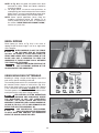
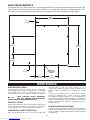
(Models 36-978, 36-979)
MODEL 36-979 SHOWN
WITH MODEL 36-B30
FENCE SYSTEM
PART NO. A13253 - 09-15-05 Rev. B
Copyright © 2005 Delta Machinery
To learn more about DELTA MACHINERY
visit our website at: www.deltamachinery.com.
For Parts, Service, Warranty or other Assistance,
please call
ESPAÑOL: PÁGINA 37
FRANÇAISE : PAGE 73
1-800-223-7278 (In Canada call 1-800-463-3582).
Downloaded from www.Manualslib.com manuals search engine
INSTRUCTION MANUAL
10" Contractor’s Saw
TABLE OF CONTENTS
IMPORTANT SAFETY INSTRUCTIONS . . . . . . . . . . . . . . . . . . . . . . . . . . . . . . . . . . . . . . . . . . . . . . . . . . . . . . . . . . . 2
SAFETY GUIDELINES. . . . . . . . . . . . . . . . . . . . . . . . . . . . . . . . . . . . . . . . . . . . . . . . . . . . . . . . . . . . . . . . . . . . . . . . . 3
TOOL WARNING LABELS . . . . . . . . . . . . . . . . . . . . . . . . . . . . . . . . . . . . . . . . . . . . . . . . . . . . . . . . . . . . . . . . . . . . . 3
GENERAL SAFETY RULES . . . . . . . . . . . . . . . . . . . . . . . . . . . . . . . . . . . . . . . . . . . . . . . . . . . . . . . . . . . . . . . . . . . . 4
ADDITIONAL SPECIFIC SAFETY RULES . . . . . . . . . . . . . . . . . . . . . . . . . . . . . . . . . . . . . . . . . . . . . . . . . . . . . . . . . 5
FUNCTIONAL DESCRIPTION . . . . . . . . . . . . . . . . . . . . . . . . . . . . . . . . . . . . . . . . . . . . . . . . . . . . . . . . . . . . . . . . . . 8
CARTON CONTENTS . . . . . . . . . . . . . . . . . . . . . . . . . . . . . . . . . . . . . . . . . . . . . . . . . . . . . . . . . . . . . . . . . . . . . . . . 8
ASSEMBLY . . . . . . . . . . . . . . . . . . . . . . . . . . . . . . . . . . . . . . . . . . . . . . . . . . . . . . . . . . . . . . . . . . . . . . . . . . . . . . . . 10
OPERATION . . . . . . . . . . . . . . . . . . . . . . . . . . . . . . . . . . . . . . . . . . . . . . . . . . . . . . . . . . . . . . . . . . . . . . . . . . . . . . . 21
TROUBLESHOOTING . . . . . . . . . . . . . . . . . . . . . . . . . . . . . . . . . . . . . . . . . . . . . . . . . . . . . . . . . . . . . . . . . . . . . . . . 33
MAINTENANCE. . . . . . . . . . . . . . . . . . . . . . . . . . . . . . . . . . . . . . . . . . . . . . . . . . . . . . . . . . . . . . . . . . . . . . . . . . . . . 35
SERVICE . . . . . . . . . . . . . . . . . . . . . . . . . . . . . . . . . . . . . . . . . . . . . . . . . . . . . . . . . . . . . . . . . . . . . . . . . . . . . . . . . . 36
ACCESSORIES . . . . . . . . . . . . . . . . . . . . . . . . . . . . . . . . . . . . . . . . . . . . . . . . . . . . . . . . . . . . . . . . . . . . . . . . . . . . . 36
WARRANTY. . . . . . . . . . . . . . . . . . . . . . . . . . . . . . . . . . . . . . . . . . . . . . . . . . . . . . . . . . . . . . . . . . . . . . . . . . . . . . . . 36
ESPAÑOL. . . . . . . . . . . . . . . . . . . . . . . . . . . . . . . . . . . . . . . . . . . . . . . . . . . . . . . . . . . . . . . . . . . . . . . . . . . . . . . . . . 37
FRANÇAIS . . . . . . . . . . . . . . . . . . . . . . . . . . . . . . . . . . . . . . . . . . . . . . . . . . . . . . . . . . . . . . . . . . . . . . . . . . . . . . . . . 73
IMPORTANT SAFETY INSTRUCTIONS
Read and understand all warnings and operating instructions before using any tool or equipment. When
using tools or equipment, basic safety precautions should always be followed to reduce the risk of personal injury.
Improper operation, maintenance or modification of tools or equipment could result in serious injury and property damage.
There are certain applications for which tools and equipment are designed. Delta Machinery strongly recommends that
this product NOT be modified and/or used for any application other than for which it was designed.
If you have any questions relative to its application DO NOT use the product until you have written Delta Machinery
and we have advised you.
Online contact form at www.deltamachinery.com
Postal Mail: Technical Service Manager
Delta Machinery
4825 Highway 45 North
Jackson, TN 38305
(IN CANADA: 125 Mural St. Suite 300, Richmond Hill, ON, L4B 1M4)
Information regarding the safe and proper operation of this tool is available from the following sources:
Power Tool Institute
1300 Sumner Avenue, Cleveland, OH 44115-2851
www.powertoolinstitute.org
National Safety Council
1121 Spring Lake Drive, Itasca, IL 60143-3201
American National Standards Institute, 25 West 43rd Street, 4 floor, New York, NY 10036 www.ansi.org
ANSI 01.1Safety Requirements for Woodworking Machines, and
the U.S. Department of Labor regulations www.osha.gov
SAVE THESE INSTRUCTIONS!
2
Downloaded from www.Manualslib.com manuals search engine
SAFETY GUIDELINES
It is important for you to read and understand this manual. The information it contains relates to protecting YOUR
SAFETY and PREVENTING PROBLEMS. The symbols below are used to help you recognize this information.
Indicates an imminently hazardous situation which, if not avoided, will result in death or serious injury.
Indicates a potentially hazardous situation which, if not avoided, could result in death or serious injury.
Indicates a potentially hazardous situation which, if not avoided, may result in minor or moderate injury.
Used without the safety alert symbol indicates potentially hazardous situation which, if not avoided, may
result in property damage.
CALIFORNIA PROPOSITION 65
SOME DUST CREATED BY POWER SANDING, SAWING, GRINDING, DRILLING, AND OTHER
CONSTRUCTION ACTIVITIES contains chemicals known to cause cancer, birth defects or other reproductive harm.
Some examples of these chemicals are:
· lead from lead-based paints,
· crystalline silica from bricks and cement and other masonry products, and
· arsenic and chromium from chemically-treated lumber.
Your risk from these exposures varies, depending on how often you do this type of work. To reduce your exposure to
these chemicals: work in a well ventilated area, and work with approved safety equipment, always wear NIOSH/OSHA
approved, properly fitting face mask or respirator when using such tools.
TOOL WARNING LABELS
Before use, read the warning labels located on the saw. Also read any warning labels that are included with the
fence installed on the saw. If the warning labels identified below are illegible or missing from the saw, contact Delta
Customer Service for free replacements. (The contact information is listed in the "SERVICE" section of this manual.)
3
Downloaded from www.Manualslib.com manuals search engine
GENERAL SAFETY RULES
READ AND UNDERSTAND ALL WARNINGS AND OPERATING INSTRUCTIONS BEFORE
USING THIS EQUIPMENT. Failure to follow all instructions listed below, may result in
electric shock, fire, and/or serious personal injury or property damage.
IMPORTANT SAFETY INSTRUCTIONS
1.
2.
3.
4.
5.
6.
7.
8.
9.
10.
11.
12.
13.
14. USE THE PROPER EXTENSION CORD. Make sure
your extension cord is in good condition. When using an
extension cord, be sure to use one heavy enough to carry
the current your product will draw. An undersized cord will
cause a drop in line voltage, resulting in loss of power and
overheating. See the Extension Cord Chart for the correct
size depending on the cord length and nameplate ampere
rating. If in doubt, use the next heavier gauge. The smaller
the gauge number, the heavier the cord.
15. SECURE THE WORKPIECE. Use clamps or a vise to
hold the workpiece when practical. Loss of control of a
workpiece can cause injury.
16. FEED THE WORKPIECE AGAINST THE DIRECTION OF
THE ROTATION OF THE BLADE, CUTTER, OR ABRASIVE
SURFACE. Feeding it from the other direction will cause the
workpiece to be thrown out at high speed.
17. DON’T FORCE THE WORKPIECE ON THE MACHINE.
Damage to the machine and/or injury may result.
18. DON’T OVERREACH. Loss of balance can make you fall
into a working machine, causing injury.
19. NEVER STAND ON THE MACHINE. Injury could occur if the
tool tips, or if you accidentally contact the cutting tool.
20. NEVER LEAVE THE MACHINE RUNNING UNATTENDED.
TURN THE POWER OFF. Don’t leave the machine until it comes
to a complete stop. A child or visitor could be injured.
21. TURN THE MACHINE “OFF”, AND DISCONNECT THE
MACHINE FROM THE POWER SOURCE before installing
or removing accessories, changing cutters, adjusting or
changing set-ups. When making repairs, be sure to lock
the start switch in the “OFF” position. An accidental startup can cause injury.
22. MAKE YOUR WORKSHOP CHILDPROOF WITH
PADLOCKS, MASTER SWITCHES, OR BY REMOVING
STARTER KEYS. The accidental start-up of a machine by
a child or visitor could cause injury.
23.
STAY ALERT, WATCH WHAT YOU ARE
DOING, AND USE COMMON SENSE.
DO NOT USE THE MACHINE WHEN YOU ARE TIRED
OR UNDER THE INFLUENCE OF DRUGS, ALCOHOL,
OR MEDICATION. A moment of inattention while operating
power tools may result in injury.
24. USE OF THIS TOOL CAN GENERATE AND DISBURSE
DUST OR OTHER AIRBORNE PARTICLES, INCLUDING
WOOD DUST, CRYSTALLINE SILICA DUST AND
ASBESTOS DUST. Direct particles away from face and
body. Always operate tool in well ventilated area and
provide for proper dust removal. Use dust collection system
wherever possible. Exposure to the dust may cause serious
and permanent respiratory or other injury, including silicosis
(a serious lung disease), cancer, and death. Avoid breathing
the dust, and avoid prolonged contact with dust. Allowing
dust to get into your mouth or eyes, or lay on your skin
may promote absorption of harmful material. Always use
properly fitting NIOSH/OSHA approved respiratory protection
appropriate for the dust exposure, and wash exposed areas
with soap and water.
FOR YOUR OWN SAFETY, READ THE INSTRUCTION
MANUAL BEFORE OPERATING THE MACHINE. Learning
the machine’s application, limitations, and specific
hazards will greatly minimize the possibility of accidents
and injury.
WEAR EYE AND HEARING PROTECTION. ALWAYS
USE SAFETY GLASSES. Everyday eyeglasses are NOT
safety glasses. USE CERTIFIED SAFETY EQUIPMENT.
Eye protection equipment should comply with ANSI Z87.1
standards. Hearing equipment should comply with ANSI
S3.19 standards.
WEAR PROPER APPAREL. Do not wear loose clothing,
gloves, neckties, rings, bracelets, or other jewelry which
may get caught in moving parts. Nonslip protective
footwear is recommended. Wear protective hair covering to
contain long hair.
DO NOT USE THE MACHINE IN A DANGEROUS
ENVIRONMENT. The use of power tools in damp or wet
locations or in rain can cause shock or electrocution. Keep
your work area well-lit to prevent tripping or placing arms,
hands, and fingers in danger.
MAINTAIN ALL TOOLS AND MACHINES IN PEAK
CONDITION. Keep tools sharp and clean for best and safest
performance. Follow instructions for lubricating and changing
accessories. Poorly maintained tools and machines can further
damage the tool or machine and/or cause injury.
CHECK FOR DAMAGED PARTS. Before using the machine,
check for any damaged parts. Check for alignment of
moving parts, binding of moving parts, breakage of parts,
and any other conditions that may affect its operation.
A guard or any other part that is damaged should be
properly repaired or replaced with Delta or factory
authorized replacement parts. Damaged parts can cause
further damage to the machine and/or injury.
KEEP THE WORK AREA CLEAN. Cluttered areas and benches
invite accidents.
KEEP CHILDREN AND VISITORS AWAY. Your shop is a
potentially dangerous environment. Children and visitors can be
injured.
REDUCE THE RISK OF UNINTENTIONAL STARTING. Make
sure that the switch is in the “OFF” position before plugging
in the power cord. In the event of a power failure, move the
switch to the “OFF” position. An accidental start-up can
cause injury. Do not touch the plug’s metal prongs when
unplugging or plugging in the cord.
USE THE GUARDS. Check to see that all guards are in
place, secured, and working correctly to prevent injury.
REMOVE ADJUSTING KEYS AND WRENCHES BEFORE
STARTING THE MACHINE. Tools, scrap pieces, and other
debris can be thrown at high speed, causing injury.
USE THE RIGHT MACHINE. Don’t force a machine or
an attachment to do a job for which it was not designed.
Damage to the machine and/or injury may result.
USE RECOMMENDED ACCESSORIES. The use of
accessories and attachments not recommended by Delta
may cause damage to the machine or injury to the user.
4
Downloaded from www.Manualslib.com manuals search engine
ADDITIONAL SPECIFIC SAFETY RULES
FAILURE TO FOLLOW THESE RULES MAY RESULT IN SERIOUS PERSONAL INJURY.
1.
2.
3.
4.
5.
6.
7.
8.
DO NOT OPERATE THIS MACHINE until it is assembled
and installed according to the instructions.
OBTAIN ADVICE FROM YOUR SUPERVISOR, instructor,
or another qualified person if you are not familiar with the
operation of this machine.
FOLLOW ALL WIRING CODES and recommended
electrical connections.
ALWAYS USE GUARDS, SPLITTER, AND ANTI-KICKBACK
PAWLS whenever possible, including through sawing. Check
to see that they are in place, secured and working correctly.
Test the anti-kickback pawl action before ripping by pushing
the wood under the anti-kickback teeth. The teeth must
prevent the wood from being thrown toward the front of the
saw.
CUTTING THE WORKPIECE WITHOUT THE USE OF A
FENCE OR MITER GAUGE IS KNOWN AS “FREEHAND”
CUTTING. NEVER perform “free-hand” operations. Use
either the fence or miter gauge to position and guide the
workpiece.
HOLD THE WORKPIECE FIRMLY against the miter gauge
or fence.
CUTTING COMPLETELY THROUGH THE WORK-PIECE
IS KNOWN AS “THROUGH-SAWING”. Ripping and crosscutting are through-sawing operations. Cutting with the
grain is ripping. Use a fence or fence system for ripping.
NEVER use a miter guage for ripping. Use push sticks for
ripping a narrow workpiece. Cutting across the grain is crosscutting. Never use a fence or fence system for cross-cutting.
Instead, use a miter gauge.
KICKBACK IS THE NATURAL TENDENCY OF THE
WORKPIECE TO BE THROWN BACK AT THE OPERATOR
when the workpiece initially contacts the blade or if the
workpiece pinches the blade. Kickback is dangerous and can
result in serious injury.
AVOID KICKBACK by:
A. keeping blade sharp and free of rust and pitch.
B. keeping rip fence parallel to the saw blade.
C. using saw blade guard and splitter for every possible
operation, including all through sawing.
D. keeping splitter aligned with sawblade.
E. keeping the anti-kickback pawls in place and
sharpened.
F. pushing the workpiece past the saw blade prior to
release.
G. never ripping a workpiece that is twisted or warped, or
does not have a straight edge to guide along the fence.
H. using featherboards when the anti-kickback device or
the guard and splitter cannot be used.
I. never sawing a large workpiece that cannot be
controlled.
J. never using the fence as a guide when crosscutting.
K. never sawing a workpiece with loose knots, flaws, nails
or other foreign objects.
L. never ripping a workpiece shorter than 10”.
SOME MATERIALS ARE TOO HARD AND
SLIPPERY FOR THE ANTI-KICKBACK
PAWLS TO BE EFFECTIVE. Plastic and compositions
(like hardboard) may be cut on your saw, but be especially
attentive to following proper set-up and cutting procedures
to prevent any kickbacks when cutting these materials.
9.
10.
11.
12.
13.
14.
15.
16.
17.
18.
19.
20.
21.
22.
23.
24.
25.
26.
USE THE CORRECT SAWBLADE FOR THE INTENDED
OPERATION. The blade must rotate toward the front of the
saw. Always tighten the blade arbor nut securely. Before use,
inspect the blade for cracks or mising teeth. Do not use a
damaged blade.
NEVER USE ABRASIVE WHEELS on this saw.
DO NOT CUT METAL WITH THIS SAW.
REMOVE CUT-OFF PIECES AND SCRAPS from the table
before starting the saw. The vibration of the machine may
cause them to move into the saw blade and be thrown out.
CUT-OFF PIECES CAN BE THROWN BACK AT THE OPE
RATOR. For large cut-off pieces, use a push stick to push the
piece past the blade and off the back of the saw table. Do not
reach across sawblade. Be careful that small pieces do not
contact the blade.
NEVER ATTEMPT TO FREE A STALLED SAW BLADE
WITHOUT FIRST TURNING THE MACHINE OFF. If a
workpiece or cut-off piece becomes trapped inside the
guard, turn saw off and wait for blade to stop before lifting
the guard and removing the piece.
NEVER START THE MACHINE with the workpiece against
the blade.
NEVER run the workpiece between the fence and a moulding
cutterhead.
KEEP ARMS, HANDS, AND FINGERS away from the blade.
Use a push stick to push small workpieces through the saw.
A push stick is a small wooden stick, usually homemade, that
should be used whenever the size or shape of the workpiece
would cause you to place your hands within six inches of the
blade. See “CONSTRUCTING A PUSH STICK” in the back of
this manual for guidance on making your own.
AVOID AWKWARD OPERATIONS AND HAND POSITIONS
where a sudden slip could cause a hand to move into the
blade.
NEVER have any part of your body in line with the path of the
saw blade.
NEVER REACH AROUND or over the saw blade.
PROPERLY SUPPORT LONG (3 feet or longer) OR WIDE
(36” or wider) WORKPIECES. If extension tables wider than
24” are attached to the saw, bolt the saw stand to the floor,
or use a sturdy outrigger support to prevent tipping.
PREVENT MOTION OF THE SAW WHILE IN USE. If the
mobility kit is installed, lower the foot pedal and level the
feet so the saw does not rock, walk, slide or tip. If necessary,
secure the stand to the floor.
NEVER PERFORM LAYOUT, assembly or set-up work on
the table/work area when the machine is running.
TURN THE MACHINE “OFF” AND DISCONNECT THE
MACHINE from the power source before installing or
removing accessories, changing the sawblade, or adjusting
or changing set-ups. Lock swicth in the “OFF” position when
making repairs.
CLEAN THE TABLE/WORK AREA BEFORE LEAVING THE
MACHINE. Lock the switch in the “OFF” position to prevent
unauthorized use.
ADDITIONAL INFORMATION regarding the safe
and
proper operation of power tools (i.e. a safety video) is
available from the Power Tool Institute, 1300 Sumner Avenue,
Cleveland, OH 44115-2851 (www.powertoolinstitute.com).
Information is also available from the National Safety Council,
1121 Spring Lake Drive, Itasca, IL 60143-3201. Please refer
to the American National Standards Institute ANSI 01.1
Safety Requirements for Woodworking Machines and the
U.S. Department of Labor OSHA 1910.213 Regulations.
SAVE THESE INSTRUCTIONS. Refer to them often and use them to instruct others.
5
Downloaded from www.Manualslib.com manuals search engine
POWER CONNECTIONS
A separate electrical circuit should be used for your machines. This circuit should not be less than #12 wire and should
be protected with a 20 Amp time lag fuse. If an extension cord is used, use only 3-wire extension cords which have
3-prong grounding type plugs and matching receptacle which will accept the machine’s plug. Before connecting the
machine to the power line, make sure the switch (s) is in the “OFF” position and be sure that the electric current is of
the same characteristics as indicated on the machine. All line connections should make good contact. Running on low
voltage will damage the machine.
DO NOT EXPOSE THE MACHINE TO RAIN OR OPERATE THE MACHINE IN DAMP LOCATIONS.
MOTOR SPECIFICATIONS
Your machine is wired for 120/240 volts, 60 HZ alternating current. Before connecting the machine to the power
source, make sure the switch is in the “OFF” position.
GROUNDING INSTRUCTIONS
THIS MACHINE MUST BE GROUNDED WHILE IN USE TO PROTECT THE OPERATOR FROM ELE
CTRIC SHOCK.
2. Grounded, cord-connected machines intended for
use on a supply circuit having a nominal rating less
than 150 volts:
1. All grounded, cord-connected machines:
In the event of a malfunction or breakdown, grounding
provides a path of least resistance for electric current
to reduce the risk of electric shock. This machine is
equipped with an electric cord having an equipmentgrounding conductor and a grounding plug. The plug
must be plugged into a matching outlet that is properly
installed and grounded in accordance with all local codes
and ordinances.
If the machine is intended for use on a circuit that has
an outlet that looks like the one illustrated in Fig. A, the
machine will have a grounding plug that looks like the plug
illustrated in Fig. A. A temporary adapter, which looks like
the adapter illustrated in Fig. B, may be used to connect
this plug to a matching 2-conductor receptacle as shown
in Fig. B if a properly grounded outlet is not available. The
temporary adapter should be used only until a properly
grounded outlet can be installed by a qualified electrician.
The green-colored rigid ear, lug, and the like, extending
from the adapter must be connected to a permanent
ground such as a properly grounded outlet box. When
ever the adapter is used, it must be held in place with a
metal screw.
Do not modify the plug provided - if it will not fit the outlet,
have the proper outlet installed by a qualified electrician.
Improper connection of the equipment-grounding cond
uctor can result in risk of electric shock. The conductor
with insulation having an outer surface that is green with
or without yellow stripes is the equipment-grounding
conductor. If repair or replacement of the electric cord
or plug is necessary, do not connect the equipmentgrounding conductor to a live terminal.
NOTE: In Canada, the use of a temporary adapter is
not permitted by the Canadian Electric Code.
Check with a qualified electrician or service personnel
if the grounding instructions are not completely underst
ood, or if in doubt as to whether the machine is properly
grounded.
IN ALL CASES, MAKE CERTAIN THAT
THE RECEPTACLE IN QUESTION IS PROPERLY GROUND
ED. IF YOU ARE NOT SURE, HAVE A QUALIFIED ELECTRI
CIAN CHECK THE RECEPTACLE.
Use only 3-wire extension cords that have 3-prong
grounding type plugs and matching 3-conductor
receptacles that accept the machine’s plug, as shown
in Fig. A. Repair or replace damaged or worn cord
immediately.
GROUNDED OUTLET BOX
GROUNDED OUTLET BOX
GROUNDING
MEANS
CURRENT
CARRYING
PRONGS
ADAPTER
GROUNDING BLADE
IS LONGEST OF THE 3 BLADES
Fig. A
Downloaded from www.Manualslib.com manuals search engine
6
Fig. B
3. 240 VOLT SINGLE PHASE OPERATION
The motor supplied with your machine is a dual voltage,
120/240 volt motor. It is shipped ready-to-run for 120
volt operation. However, it can be converted for 240 volt
operation.
GROUNDED OUTLET BOX
CURRENT
CARRYING
PRONGS
A qualified electrician should do the conversion, or the
machine can be taken to an Authorized Delta Service
Center. When completed, the machine must conform
to the National Electric Code and all local codes and
ordinances.
GROUNDING BLADE
IS LONGEST OF THE 3 BLADES
The machine is converted by re-wiring the motor for 240
volts, installing a 240 volt plug on the power supply cord
and replacing the switch (if necessary) with one that is
rated for 240 volt operation.
Fig. C
IN ALL CASES, MAKE CERTAIN THAT
THE RECEPTACLE IN QUESTION
IS PROPERLY GROUNDED. IF YOU
ARE NOT SURE, HAVE A QUALIFIED ELECTRICIAN
CHECK THE RECEPTACLE.
Be sure the 240 volt plug is only used in an outlet having
the same configuration as the plug illustrated in Fig. C.
No adapter should be used with the 240 volt plug.
EXTENSION CORDS
USE PROPER EXTENSION CORDS. MAKE SURE YOUR EXTENSION CORD IS IN GOOD
CONDITION AND IS A 3-WIRE EXTENSION CORD WHICH HAS A 3-PRONG GROUNDING TYPE PLUG AND
MATCHING RECEPTACLE WHICH WILL ACCEPT THE MACHINE’S PLUG. WHEN USING AN EXTENSION CORD,
BE SURE TO USE ONE HEAVY ENOUGH TO CARRY THE CURRENT OF THE MACHINE. AN UNDERSIZED CORD
WILL CAUSE A DROP IN LINE VOLTAGE, RESULTING IN LOSS OF POWER AND OVERHEATING. FIG. D-1 OR D2, SHOWS THE CORRECT GAUGE TO USE DEPENDING ON THE CORD LENGTH. IF IN DOUBT, USE THE NEXT
HEAVIER GAUGE. THE SMALLER THE GAUGE NUMBER, THE HEAVIER THE CORD.
MINIMUM GAUGE EXTENSION CORD
MINIMUM GAUGE EXTENSION CORD
RECOMMENDED SIZES FOR USE WITH STATIONARY ELECTRIC MACHINES
RECOMMENDED SIZES FOR USE WITH STATIONARY ELECTRIC MACHINES
Ampere
Rating
Volts
Total Length
of Cord in Feet
Gauge of
Extension Cord
Ampere
Rating
Volts
Total Length
of Cord in Feet
Gauge of
Extension Cord
0-6
0-6
0-6
0-6
120
120
120
120
up to 25
25-50
50-100
100-150
18 AWG
16 AWG
16 AWG
14 AWG
0-6
0-6
0-6
0-6
240
240
240
240
up to 50
50-100
100-200
200-300
18 AWG
16 AWG
16 AWG
14 AWG
6-10
6-10
6-10
6-10
120
120
120
120
up to 25
25-50
50-100
100-150
18 AWG
16 AWG
14 AWG
12 AWG
6-10
6-10
6-10
6-10
240
240
240
240
up to 50
50-100
100-200
200-300
18 AWG
16 AWG
14 AWG
12 AWG
10-12
10-12
10-12
10-12
120
120
120
120
up to 25
25-50
50-100
100-150
16 AWG
16 AWG
14 AWG
12 AWG
10-12
10-12
10-12
10-12
240
240
240
240
up to 50
50-100
100-200
200-300
16 AWG
16 AWG
14 AWG
12 AWG
12-16
12-16
12-16
120
120
120
up to 25
25-50
14 AWG
12 AWG
12-16
12-16
12-16
240
240
240
up to 50
50-100
14 AWG
12 AWG
GREATER THAN 50 FEET NOT RECOMMENDED
Fig. D-2
Fig. D-1
7
Downloaded from www.Manualslib.com manuals search engine
GREATER THAN 100 FEET NOT RECOMMENDED
FUNCTIONAL DESCRIPTION
FOREWORD
Delta Models 36-978 and 36-979 are left-tilting 10" contractor saws with a built-in mobility kit. The saws have a powerful
1½ HP induction motor which can handle tough cutting operations. The 36-978 comes with sheet metal wings and the
36-979 comes with cast iron wings.
A RIP FENCE ASSEMBLY IS NOT PACKAGED WITH THE PRODUCT. YOU MUST INSTALL AND USE
A RIP FENCE SYSTEM FOR RIPPING OPERATIONS. SEE THE SECTION “ACCESSORIES” FOR
AVAILABLE FENCE SYSTEMS.
NOTICE: The photo on the manual cover illustrates the current production model. All other illustrations contained in
the manual are representative only and may not depict the actual labeling or accessories included. These are intended
to illustrate technique only.
CARTON CONTENTS
TABLE SAW PARTS
4
3
2
5
7
1
8
6
1.
2.
3.
4.
5.
6.
7.
8.
9.
10.
11.
12.
13.
14.
15.
16.
17.
18.
19.
20.
21.
22.
23.
Table Saw
Handwheel (2)
Miter Gauge Body
Miter Gauge handle and washer
Pin (2)
Spring
7/8" Open End Wrench
7/8" and 1/2" Close End Wrench
Drive Belt
Saw Blade
4mm Allen Wrench
Wrench Hook
Lock Knob (2)
Blade Guard and Splitter Assembly
Motor Pulley
Motor
Table Insert
Belt Guard
Motor Plate
Dust Collector Adaptor
Splitter Bracket
Pulley Guard Plate
Back Brace
10
11
13
12
16
15
17
14
20
19
18
22
Fig. 1
8
Downloaded from www.Manualslib.com manuals search engine
9
21
23
EXTENSION WINGS
MODEL 36-978
2 SHEET METAL
EXTENSION WINGS
MODEL 36-979
2 CAST IRON EXTENSION
WINGS
Fig. 2
STAND AND MOBILE BASE PARTS
35
26
25
34
24
28
29
30
31
32
27
33
Fig. 3
24.
25.
26.
27.
28.
29.
Plastic Foot (4)
Corner Bracket (left side)
Corner Bracket (right side)
Wheel (2)
Short Side Leg Support (2)
Long Side Leg Support (2)
30.
31.
32.
33.
34.
35.
9
Downloaded from www.Manualslib.com manuals search engine
Leg (4)
Short Panels For Back and Front (2)
Long Panels for Sides (2)
Leveling Feet (2)
Foot Lever Assembly
Caster Assembly
HARDWARE
1
2
8
30
23
15
31
24
9
16
3
10
17
4
11
18
5
12
25
32
33
26
19
27
20
6
7
28
34
13
21
14
29
22
Fig. 4
1.
2.
3.
4.
5.
6.
7.
8.
9.
10.
11.
12.
13.
14.
15.
16.
17.
18.
19.
/16-20 x 3/4" Hex Head Screw (6) (For Sheet Metal)
7
/16-20 x 11/4" Hex Head Screw (6) (For Cast Iron)
3
/8-16 x 11/2" Flat Head Screw (1)
5
/16-18 x 3/4" Carriage Head Screw (12)
5
/16-18 x 5/8" Carriage Head Screw (42)
1
/4-20 x 11/2" Hex Head Screw (1)
1
/4-20 x 3/4" Hex Head Screw (2)
7
/16" Flat Washer (6)
3
/8" Flat Washer (1)
5
/16" Flat Washer (37)
1
/4" Flat Washer (3)
Pin (2)
Spring (1)
Motor Pulley Key (1)
7
/16" Lockwasher (6)
3
/8" Lockwasher (1)
5
/16" External Tooth Lockwasher (4)
1
/4" Lockwasher (2)
1
/4" External Tooth Lockwasher (2)
7
20.
21.
22.
23.
24.
25.
26.
27.
28.
29.
30.
31.
32.
33.
34.
/16-18 Hex Nut (5)
/8-16 Hex Nut (1)
1
/4-20 Hex Nut (1)
1
/4-20 Wing Nut (1)
Spacer (1)
5
/16-18 Serrated Hex Nut (42)
5
/16-18 x 21/4” Hex Head Cap Screw (2)
5
/16-18 Nylok Nut (3)
5
/16-18 Hex Jam Nut (4)
M8 x 20 Hex Head Screw
M8 Flat Washer (6)
M8 Lock Washer (3)
M8 Hex Nut (3)
5
/16-18 x 4” Hex Head Cap Screw (1)
M4 x 8mm Pan Head Cap Screw (2)
5
3
UNPACKING AND CLEANING
Carefully unpack the machine and all loose items from the shipping container(s). Remove the rust-preventative oil from
unpainted surfaces using a soft cloth moistened with mineral spirits, paint thinner or denatured alcohol.
DO NOT USE HIGHLY VOLATILE SOLVENTS SUCH AS GASOLINE, NAPHTHA, ACETONE OR LACQUER
THINNER FOR CLEANING YOUR SAW.
After cleaning, cover the unpainted surfaces with a good quality household floor paste wax.
ASSEMBLY
ASSEMBLY TOOLS REQUIRED
*7/8" Open End Wrench (supplied)
* 7/8" and 1/2" Close End Wrench (supplied)
* 4mm Allen Wrench (supplied)
* 1/4” Allen Wrench (not supplied)
* Socket or Open-End Wrenches, including 10mm, 12mm, 18mm,1/2 inch and 9/16 inch (not supplied)
ASSEMBLY TIME ESTIMATE
Assembly for this machine takes approximately 4-6 hours.
10
Downloaded from www.Manualslib.com manuals search engine
FOR YOUR OWN SAFETY, DO NOT CONNECT MACHINE TO POWER SOURCE UNTIL MACHINE IS
COMPLETELY ASSEMBLED AND YOU READ AND UNDERSTAND THE INSTRUCTION MANUAL.
MOBILE BASE AND STAND ASSEMBLY
The mobile base and stand should be put
together upside down to ease assembly. To
assemble the mobile base and stand:
B
D
A
FRONT AND SIDE PANELS
1. Insert a 5/16-18 x 5/8" Carriage Head
Screw (A) Fig. 5 through the leg (B) and
then corresponding hole in the panel
(C) as shown in Fig. 5. NOTE: Make
sure the squares of hex screw align
with the flat sides of the hole opening.
2. Thread a 5/16-18 Serrated Hex Nut (D)
around screw and finger tighten panel
to leg, as shown in Fig. 6. Make sure the
serrated face of the hex nut is against
the panel. NOTE: HAND TIGHTEN
ONLY FOR LATER ADJUSTMENTS.
3. Fig. 7 shows all four legs attached to
the front and side panels. NOTE: Make
sure short panels are opposite each
other and that long panels are opposite
each other.
SHORT AND LONG LEG SUPPORTS
4. Attach long side leg supports (E) Fig.
8 and short side leg supports to the
legs using 5/16-18 x 5/8" Carriage Head
Screws and 5/16-18 Serrated Hex Nuts.
Insert the screw through the leg first
and then the support. NOTE: Be
sure the holes (J) Fig. 9 in all side
supports will be aligned as shown after
assembly.
5. Thread hex nut onto screw and finger
tighten only. At this time, only assemble
eight screws and eight nuts into holes
- two of which are shown at (F) Fig. 9.
Make sure these are the holes which
will be on the bottom (after saw is
turned right side up).
CORNER BRACKETS
6. Take corner bracket (G) Fig. 10 with
the closed end and align holes (H) with
holes (I) in the leg supports. NOTE:
MAKE SURE THE CLOSED-END
BRACKETS (G) ARE ATTACHED TO
THE LONG LEG SUPPORT WHICH
HAS THE THREE HOLES IN THE
MIDDLE, AS SHOWN IN FIG.13.
It may be necessary to take a soft
hammer (or a regular hammer and
block of wood) to tap in the corner
bracket to align holes, as in Fig. 11.
7. Once aligned, attach the corner
bracket to the leg supports using the
5
/16-18 x 5/8" Carriage Head Screws and
5
/16-18 Serrated Hex Nuts. Insert screw
through support and then the corner
bracket at (K) Fig. 12. Thread hex nut
onto screw and tighten.
8. Then attach leg to corner bracket
using the longer 5/16-18 x 3/4" Carriage
Head Screws and 5/16-18 Serrated Hex
Nuts in two holes, one of which is at (L)
Fig. 12.
C
E
Fig. 7
Fig. 8
I
J
G
H
F
F
Fig. 9
Fig. 10
K
L
Fig. 11
Fig. 12
M
G
Fig. 13
11
Downloaded from www.Manualslib.com manuals search engine
Fig. 6
Fig. 5
Fig. 14
9.
Repeat for other similar corner
bracket. These brackets, (G) Fig. 13
are where the rubber leveling feet will
be installed.
10. The brackets with the open end, as
shown at (M) Fig. 14, are attached
in a similar manner as described in
Steps 6 to 9. NOTE: MAKE SURE
THE OPEN END IS ALIGNED
AS SHOWN IN FIGS. 14 AND 15.
THE WHEELS WILL BE INSTALL
ED INSIDE THESE BRACKETS,
AS SHOWN IN FIG. 20.
M
Fig. 17
Fig. 15
O
N
P
LEVELING FEET
11. Take leveling feet (shown at 33 in Fig.
3) and thread one 5/16-18 Hex Jam Nut
all the way onto the screw post. Insert
screw post into hole of enclosed
corner bracket as shown in Fig. 17.
Place another 5/16-18 Hex Jam Nut
onto the post and tighten. Move hex
nuts up or down post to adjust the
height of the foot. Repeat for the other
leveling foot.
Fig. 19
Fig. 18
WHEELS
12. Place a wheel (N) Fig. 19 in an open
end bracket (O) Fig. 19. Insert a 5/16-18
x 21/4” Hex Head Cap Screw (No. 26
in Fig. 4) through the bracket and the
wheel. Fasten it together as shown in
Fig. 19 with a 5/16-18 Nylok Nut (P).
13. Fig. 20 shows the leveling feet and the
wheels properly assembled.
14. NOW, TIGHTEN ALL HARDWARE.
Tighten panels first, and then leg
supports.
ATTACHING FOOT LEVER ASSEMBLY
TO BASE
The Foot Lever and Caster Assembly are
assembled together by placing the Foot
Lever (R) over the Caster Assembly (S)
Fig. 21 and lining up the holes (T) and (U).
Then, insert a 5/16-18 x 4” Hex Head Screw
though hole (T) and fasten in place with a
5
/16-18 Nylock Nut (V) Fig. 22.
Assemble the Foot Lever to the base by
lining up the three holes in the Foot Lever
(W) Fig. 23 with the three holes in the base
(X) Fig. For each hole, place an M8 Flat
Washer on an M8 x 20 Hex Head Screw
and insert screw into hole. Then fasten to
base by placing an M8 Flat Washer, M8
Lock Washer and M8 Hex Nut onto the
screw and tighten.
T
R
S
U
Q
Fig. 21
Fig. 20
X
V
W
Fig. 23
Fig. 22
PLASTIC FEET
Install the Plastic Feet (Y) Fig. 24 by placing them around radius at end of legs as shown.
Tap the feet in place with a soft hammer or using a regular hammer and a block of wood.
ADDING AN OPTIONAL SHELF
If you desire, you can install a shelf made from a piece of 3/4-inch plywood measuring 223/8”
x 191/4” (568.96 mm x 488.95 mm). To install, screw the wood to the leg supports through
the (8) holes in the leg supports, six of which are shown at (Q) Fig. 20. When the saw is
upside down (as in Fig. 20) the shelf would be placed underneath the overhangs of the
leg supports. When the saw is flipped right-side up, the shelf would be on top of the leg
support overhangs. To install the shelf, it will be necessary to remove one side panel. Make
sure this panel is re-installed before using the saw. See exact measurements for shelf in
the back of this manual.
12
Downloaded from www.Manualslib.com manuals search engine
Y
Fig. 24
DUST CHUTE AND BACK BRACE
A
C
B
DO NOT INSTALL DUST CHUTE UNLESS
A DUST COLLECTOR WILL BE USED.
To install the dust chute and back brace, place the saw
unit upside down on the floor as shown in Fig. 25.
PROTECT THE SAW’S TABLE TOP
BY PLACING SOMETHING BETWEEN
THE SAW AND THE FLOOR, SUCH AS A PIECE OF
CARDBOARD, CARPET ETC.
To install dust chute (A) Fig. 25, slide it in as shown.
Place back brace (B) with tabs (C) Fig. 25 below the
chute edge as shown in Fig. 26. To fasten the back
brace to the saw unit, place 5/16-18 x 5/8" Carriage Head
Screws up from inside the saw cabinet through holes
(E). Thread 5/16-18 Serrated Hex Nuts on the screws and
tighten securely.
Fig. 25
D
E
D
MOBILE BASE AND STAND
ASSEMBLY TO SAW
TO PREVENT PERSONAL INJURY OR
DAMAGE TO THE MACHINE, ASSEMBLE THE STAND
TO THE SAW AS FOLLOWS:
1. With the saw already upside down from installing
the dust chute and back brace, place the mobile
base and stand assembly on top of the upsidedown saw and align the eight holes in the legs (two
of which are shown at (A) Fig. 27) with the eight
holes (D) Fig. 26.
NOTE: Make certain the shorter panel with the Delta
nameplate is on the front of the saw next to the
scale and pointer.
2. In the holes (D) Fig. 26, place a 5/16-18 x 5/8" Carriage
Head Screw up from inside the saw cabinet and
then through the legs. Thread a 5/16-18 Serrated Hex
Nut on the screw and tighten securely. Repeat for all
eight holes.
3.
WITH A MINIMUM OF TWO PEOPLE,
CAREFULLY TURN THE SAW AND
STAND UPRIGHT AS SHOWN IN FIG. 28.
4. To make sure the table is level, kick up the foot pedal
(C) Fig. 28 to disengage the mobile base. Check to
see if table is level. If not, make adjustments to the
leveling feet as described in “LEVELING FEET” section
D
Fig. 26
A
Fig. 27
on the previous page. To raise saw onto the wheels, push
down on foot pedal.
C
Fig. 28
13
Downloaded from www.Manualslib.com manuals search engine
BLADE TILTING
AND RAISING HANDWHEEL
C
A
1. Place blade tilting handwheel (A) Fig. 29, onto shaft
(B). Make certain slot (C) in handwheel is engaged
with roll pin (D) on the shaft.
2. Place a 10mm Nylon Flat Washer (E) onto shaft (B)
and then thread locking knob (F), onto the shaft.
3. Assemble the blade raising handwheel (G) Fig. 30,
to the front of the saw in the same manner.
D
B
E
F
WRENCH HOOK
A hook (H) Fig. 30 for blade wrench storage can be
installed in two holes on the side of the saw as shown
using two M4x8mm Pan Head Cap Screws.
B
Fig. 29
H
G
Fig. 30
MOTOR TO MOTOR
MOUNTING PLATE
B
Assemble motor (A) to motor mounting plate (B) as shown
in Fig. 31. Align the four mounting holes in the motor
with the four holes in the mounting plate. Insert a 5/16-18x
¾" Carriage Bolt (C), through the hole in motor and then
through the hole in the motor mounting plate, place a 5/16"
Flat Washer (D), then a 5/16" External Tooth Washer (E) onto
the carriage head bolt, and fasten with a 5/16-18 Hex nut
(F). Repeat this process for the three remaining holes in
the motor and the motor mounting plate.
A
NOTE: Do not completely tighten the hex nuts at this
time.
C
Fig. 31
14
Downloaded from www.Manualslib.com manuals search engine
D
E
F
MOTOR AND MOTOR MOUNTING
PLATE TO SAW
H
1. Insert the tapered end of pin (G) Fig. 32, into the
inside holes in each side of bracket (H).
3. Assemble spring (I) Fig. 32, onto the non-tapered
end of each pin (G) as shown.
G
I
4. Position motor and motor mounting plate (A) Fig. 33,
below bracket (B) to allow bracket arm to slide through
large opening (C) in motor mounting plate (A).
G
G
Fig. 32
5. Depress pins, one of which is shown at (D) Fig. 33,
on both sides of bracket (B) and lift up motor mounting
plate (A) until pins (D) are engaged in holes (E) Fig. 33, of
motor mounting plate (A).
C
A
B
6. Fig. 34, illustrates the motor and motor mounting
plate assembled to the rear of the saw.
D
E
Fig. 33
MOTOR PULLEY, PULLEY GUARD,
AND DRIVE BELT
1. Remove the motor shaft key (No. 14, Fig. 4) that is
taped to the motor.
2. Insert key (F) Fig. 35, in the keyway on the motor
shaft. Assemble motor pulley (G) on motor shaft as
shown, with the hub of the pulley out. Tighten set
screw (H) against key (F) in motor shaft.
Fig. 34
F
H
G
Fig. 35
15
Downloaded from www.Manualslib.com manuals search engine
3. Slide the belt and pulley guard bracket (I) Fig. 36,
between the motor plate (J) and motor mounting
plate (K), as shown.
L
4. Place a ¼" External Tooth Lockwasher onto a ¼-20
x 1 ½" Hex Head Screw. Insert the screw (L) Fig. 36,
through the hole in the belt and pulley guard bracket
(I) as shown in Fig. 36.
5. Position belt and pulley guard bracket (I) Fig. 37, so
the motor pulley (K) is centered and through the hole
in the belt and pulley guard bracket (I), as shown in
Fig. 37. Tighten the four hex nuts (C) Fig. 31 that
fasten the motor to the motor mounting plate.
I
J
K
Fig. 36
6. Using a straight edge, align the motor pulley with the
arbor pulley in the saw cabinet. If necessary, adjust
the motor pulley (K) Fig. 37, in or out on the motor
shaft.
I
P
Q
L
7. Lift up on the motor and assemble the drive belt
(L) Fig. 38, to the arbor pulley and motor pulley (K)
Fig 38. The weight of the motor will provide the
correct belt tension.
K
8.
IMMEDIATELY AFTER ASSEMBLING
THE BELT, RAISE THE SAW BLADE
TO ITS MAXIMUM HEIGHT AND TILT THE SAW BLADE
TO 45 DEGREES. USING A STRAIGHT EDGE (M) FIG.
39, CHECK TO SEE IF THE MOTOR END (N) FIG. 39,
IS BELOW THE TOP OF THE TABLE SURFACE (O). IF
THE MOTOR END IS ABOVE THE TOP OF THE TABLE
SURFACE, LOOSEN THE FOUR HEX NUTS (F) FIG. 31,
RE-POSITION MOTOR AND THEN RETIGHTEN THE
NUTS. THEN, RE-ALIGN THE MOTOR PULLEY (K) FIG. 38
TO THE ARBOR PULLEY.
Fig. 37
L
K
Fig. 38
M
O
N
Fig. 39
16
Downloaded from www.Manualslib.com manuals search engine
9. Place a ¼" flat washer and then a spacer (P) onto
the ¼-20x1-1/2" hex head screw (L) Fig. 37. Then
thread a ¼-20 Hex Nut (Q) Fig. 37, onto the screw
post until it tightens the spacer onto the pulley guard
(I) Fig. 37.
10. Align the hole (S) Fig. 40 in the belt guard (R) with
the ¼-20x1 ½" hex head screw (L) Fig. 37. Place the
screw through the hole in the belt guard (R) Fig. 40.
Place a ¼" External Tooth Lockwasher onto the hex
head screw and thread a 1/4-20 Wing Nut onto the
hex head screw, and tighten securely.
S
R
MAKE CERTAIN THE BELT GUARD
DOES NOT TOUCH THE DRIVE BELT
OR MOTOR PULLEY.
Fig. 40
CONNECTING MOTOR CORD
TO SWITCH ASSEMBLY
Insert the pronged motor plug (A) Fig. 41, into the female
receptacle (B) of switch-to-motor cord, which is located
inside the saw housing.
B
MAKE SURE THE CORD RUNNING
FROM THE SWITCH TO THE FEMALE
END (B) FIG. 41 IS CLAMPED TO THE INNER WALL OF
THE SAW UNIT AND WILL NOT COME IN CONTACT
WITH THE BLADE OR ANY MOVING PARTS.
A
Fig. 42 illustrates the motor cord connected to the
switch assembly.
Fig. 41
REMOVING MOTOR FOR
TRANSPORT
To remove the motor for transport through narrow
doorways, first unplug the motor cord from the switch
cord. Then, while holding the motor, press in on pins
(G) Fig. 32 and lower motor off of bracket (B) Fig. 33.
Fig. 42
17
Downloaded from www.Manualslib.com manuals search engine
BLADE GUARD AND SPLITTER
ASSEMBLY AND ALIGNMENT
B
1. Fasten the rear splitter mounting bracket (A) Fig.
43, to the rear trunnion. Align the two holes in the
rear splitter mounting bracket (shown at B) with the
two holes in the trunnion. Place a ¼" Lock Washer
onto a ¼ -20 x ¾" Hex Head Screw, place a ¼"
Flat Washer onto the hex head screw, insert the
hex head screw through the hole in the rear splitter
mounting bracket and thread the hex head screw
into the rear trunnion. Repeat this process for the
remaining hole. Do not completely tighten the two
screws (B) at this time.
A
Y
X
Z
Fig. 43
2. Raise saw arbor to its highest position.
C
3. Remove screw and large washer (C) Fig. 44 from the
inside splitter mounting bracket.
Fig. 44
D
4. Using a straight edge, check to see if the top and
bottom of the inside splitter bracket (D) Fig. 45 is
aligned with the inner arbor flange (E), as shown.
E
Fig. 45
D
5. If alignment is necessary, loosen the two screws
(F) Fig. 46, align bracket (D) with the arbor flange
and tighten screws (F).
C
F
6. Loosely assemble large washer and screw (C) Fig. 46
to the inside splitter bracket. This screw and washer
was removed in STEP 3.
Fig. 46
18
Downloaded from www.Manualslib.com manuals search engine
7. Assemble the blade guard and splitter assembly
(G) Fig. 47, between the large washer (C) and the
splitter bracket and tighten screw (H) with wrench
supplied. Slide splitter as far down as it will go.
G
H
C
Fig. 47
8. Fasten the rear of the blade guard and splitter bracket
assembly (G) Fig. 48, to the rear splitter mounting
bracket. Align the hole (J) in the blade guard and
splitter bracket with the hole in the rear splitter
mounting bracket. Insert a 5/16-18 x 5/8" Carriage
Head Screw through the hole and place a 5/16" Flat
Washer on the screw and fasten with a 5/16-18 Hex
Nut, and tighten securely.
L
G
J
IMPORTANT: The splitter (G) Fig. 49, has a notch (L) cut
in the top edge as shown. This feature will enable the
blade guard to stay in the raised position to make blade
changing easier. Raise the front of blade guard (M), until
the rear edge of the blade guard slips into notch (L) of
splitter (G); the blade guard will stay in this position. This
feature only works when the table insert is removed.
Fig. 48
M
L
9. With the blade guard (L) Fig. 50, in the raised
position, attach the saw blade (K) on the arbor with
the two arbor wrenches provided (No. 7 and 8,
Fig. 1). For more instructions on changing blades,
see “CHANGING THE SAW BLADE” section in this
manual.
G
Fig. 49
L
K
Fig. 50
19
Downloaded from www.Manualslib.com manuals search engine
10. Using a straight edge, check to see if the rear of
the splitter (G) is aligned with the saw blade, as
shown in Fig. 51. If alignment is necessary, loosen
the screws (B) Fig. 43, align splitter (G) with the saw
blade, and tighten two screws (B) Fig. 43.
G
11. Lower saw blade and install table insert (P) Fig. 52,
in the saw table as shown.
THE TABLE INSERT SHOULD BE LEVEL
WITH THE TABLE SURFACE. IF AN
ADJUSTMENT IS NECESSARY, SEE THE SECTION
“ADJUSTING TABLE INSERT”.
Fig. 51
WHEN INSTALLING THE TABLE
INSERT, ALWAYS MAKE CERTAIN TO HOLD ON
TO THE BLADE GUARD (L). THE INSERT WILL
AUTOMATICALLY RELEASE THE HOLDING ACTION
ON THE SPLITTER AND LOWER THE BLADE GUARD
WHEN IT IS INSTALLED IN THE TABLE OPENING.
L
P
EXTENSION WINGS
1. Attach extension wing (A) Fig. 53, to the saw table.
Align the three holes in the extension wing with the
three holes in the side of the saw table.
FOR 36-978: Place a 7/16" Lockwasher (C) Fig. 53, then
a 7/16" Flat Washer (D) on a 7/16-20 x 3/4" Hex
Head Screw (B).
FOR 36-979: Place a 7/16" Lockwasher (C) Fig. 53, then
a 7/16" Flat Washer (D) on a 7/16-20 x 1¼" Hex
Head Screw (B).
Fig. 52
2. Insert the screw through the hole in the extension
wing and thread the screw into the tapped hole in
the side of the saw table. Finger tighten only. Repeat
this process for the two remaining holes in the
extension wing and the saw table.
C
D
B
NOTE: MAKE SURE FRONT EDGE OF EXTENSION
WING IS FLUSH TO OR SLIGHTLY BEHIND THE
FRONT EDGE OF THE TABLE.
C
A
3. With a straight edge (E) Fig. 53, align the
extension wing (A) level with the saw table before
fully tightening the three screws (B). Starting with
the screw at the front, tighten the screw while
keepng the extension wings aligned with the table.
Then, move to the middle screw and follow the
same procedure of aligning and tightening. Then do
the same for the third screw.
Fig. 53
MODEL 36-978 ONLY
4. Assemble the other sheet metal extension wing to
the opposite side of the saw table in the same manner.
MODEL 36-979 ONLY
4. Assemble the other cast iron extension wing to the
opposite side of the saw table in the same manner.
20
Downloaded from www.Manualslib.com manuals search engine
E
D
ON/OFF SWITCH
G
H
F
J
Insert a 3/8-16x 1½" Flat Head Screw (F) Fig. 54,
through hole (B) in the front the saw table and then
through the hole (E) in the switch bracket. Place a 3/8"
Flat Washer (G), then a 3/8" Lockwasher (H), onto the
screw (F). Then thread a 3/8-16 Hex Nut (J) onto the
screw and tighten securely.
B
E
Fig. 54
OPERATION
OPERATIONAL CONTROLS AND ADJUSTMENTS
A
B
A
Fig. 55
Fig. 56
STARTING AND STOPPING SAW
MAKE SURE THAT THE SWITCH IS IN THE “OFF” POSITION BEFORE PLUGGING CORD INTO
OUTLET. DO NOT TOUCH THE PLUG’S METAL PRONGS WHEN UNPLUGGING OR PLUGGING IN THE CORD.
1. The ON/OFF switch is located underneath the switch shield (A) Fig. 55. To turn the saw “ON”, move
switch lever (B) to the up position.
2. To turn the saw “OFF”, push down on switch shield (A) Fig. 56.
LOCKING SWITCH IN THE “OFF” POSITION
IMPORTANT: When the machine is not in use, the
switch should be locked in the “OFF” position to prevent
unauthorized use, using a padlock (C) Fig. 57 with a 3/16"
diameter shackle (D).
C
IN THE EVENT OF A POWER OUTAGE
(SUCH AS A BREAKER OR FUSE
TRIP), ALWAYS MOVE THE SWITCH TO THE “OFF”
POSITION UNTIL THE MAIN POWER IS RESTORED.
D
Fig. 57
21
Downloaded from www.Manualslib.com manuals search engine
OVERLOAD PROTECTION
A
The motor supplied with your saw is equipped with a
manual reset overload (A) Fig. 58. If the motor shuts
off or fails to start due to overloading (cutting stock
too fast, using a dull blade, using the saw beyond its
capacity, etc.), or low voltage, move the ON/OFF switch
to the “OFF” position, let the motor cool three to five
minutes and push the reset button (A), which will reset
the overload device. The motor can then be turned on
again in the usual manner.
RAISING AND LOWERING BLADE
To raise the saw blade, loosen lock knob (C) Fig. 59, and
turn the blade raising handwheel (D) clockwise. When
the blade is at the desired height, tighten lock knob (C).
Fig. 58
A
To lower the blade, loosen lock knob (C) and turn the
handwheel (D) counterclockwise. NOTE: One full turn
of the handwheel will change blade height approximately 1/4".
C
TILTING THE BLADE
D
To tilt the saw blade for bevel cutting, loosen lock knob
(A) and turn the tilting handwheel (B). When the desired
blade angle is obtained, tighten lock knob (A).
B
Fig. 59
ADJUSTING 90 DEGREE AND
45 DEGREE POSITIVE STOPS
A
B
Your saw is equipped with positive stops that will quickly
and accurately position the saw blade at 90 degrees and
45 degrees to the table. To check and adjust the positive
stops, proceed as follows:
DISCONNECT MACHINE FROM
POWER SOURCE.
F
Fig. 60
1. Raise the saw blade to its highest position.
2. Set the blade at 90 degrees to the table by turning the
blade tilting handwheel (B) Fig. 59 counterclockwise
as far as it will go.
3. Using a combination square (A) Fig. 60, check to see
if the blade is at 90 degrees to the table surface as
shown.
4. If the blade is not at 90 degrees to the table, move
the blade off of the stop by turning the handwheel (B)
Fig. 59 one turn clockwise. Loosen set screw (F) Fig.
60 with a 4mm hex wrench. Turn the blade tilting
handwheel until the blade is at 90 degrees to the
table. Tighten set screw (F) until it bottoms.
5. Adjust the hairline indicator (D) Fig. 61, to point to the
zero degree mark on the scale by loosening screws
(E), adjusting pointer (D), and tightening screws (E).
6. Turn the blade tilting handwheel clockwise as far as it
will go and using a combination square, check to see
if the blade is at 45 degrees to the table.
E
D
Fig. 61
7. If the blade is not at 45 degrees to the table, move
the blade off of the stop by turning the handwheel (B)
Fig. 59 one turn counter-clockwise. Loosen set screw
(B) Fig. 60, and turn blade tilting handwheel until the
blade is 45 degrees to the table. Tighten set screw (B)
until it bottoms.
22
Downloaded from www.Manualslib.com manuals search engine
ASSEMBLING MITER GAUGE
A
B
Place a flat washer (A) Fig. 62 on the threads of the miter
gauge lock handle (B) and then thread the handle into
the hole (C) in miter gauge bar.
Insert washer (D) Fig. 64 into the miter gage slot (E) and
slide miter gauge onto saw table.
C
MITER GAUGE OPERATION AND
ADJUSTMENT
Fig. 62
The miter gauge is equipped with adjustable index stops
at 90, 75, 60, 45 and 30 degrees.
To rotate the miter gauge, loosen lock knob (A) Fig. 63,
push the thumb lever (B) down and move the body of the
miter gage (C) to the desired angle.
A
The miter gauge is equipped with a washer (D) Fig. 64
which fits into the T-Slot groove (E) in the table. This
allows the miter gauge to be pulled off the front edge of
the table without falling. This allows for a longer cut-off
capacity in front of the blade.
C
B
Fig. 63
D
E
Fig. 64
ADJUSTING TABLE INSERT
B
DISCONNECT MACHINE FROM POWER
SOURCE.
A
C
Place a straight edge across the table at both ends of
the table insert (A) Fig. 65.
THE TABLE INSERT (A) SHOULD
ALWAYS BE LEVEL WITH THE TABLE.
B
If an adjustment is necessary, turn the adjusting screws
(B), as needed. The table insert is equipped with a finger
hole (C) for easy removal.
Fig. 65
23
Downloaded from www.Manualslib.com manuals search engine
ALIGNING MITER SLOTS TO BLADE
The saw table has been aligned at the factory so the
miter gauge slots are parallel to the saw blade. However,
it is recommended to check the alignment before initial
operation as follows:
A
DISCONNECT MACHINE FROM POWER
SOURCE.
1. Place a combination square (A) Fig. 66, on the table
with one edge of the square in the miter gauge
slot, as shown, and adjust the square so the ruler
just touches one of the teeth on the saw blade at
the forward position, as shown in Fig. 66. Lock the
square in this position.
Fig. 66
2. Rotate the saw blade so that the same tooth you
used in STEP 2 is in the rear position, as shown in
Fig. 67, and check this distance. Both the front and
rear measurements should be identical.
3. If an adjustment is necessary, loosen the two hex
head bolts (B) Fig. 68 that hold the rear trunnion to
the saw table.
A
4. Using a rubber mallet (or a regular hammer and a
block of wood), tap the trunnion (C) until a position is
found which brings the saw blade to the center of the
table insert slot, and parallel to the miter gauge slot.
Fig. 67
5. Tighten the two hex head bolts that were loosened in
STEP 3.
B
6. Tilt the blade to 45 degrees, and turn the saw blade by
hand, and insure it does not contact the table insert.
C
CHANGING THE SAW BLADE
USE ONLY 10" DIAMETER BLADES WITH
5/8" ARBOR HOLES, RATED AT 3600 RPM
OR HIGHER.
D
DISCONNECT MACHINE FROM POWER
SOURCE.
1. NOTE: Two 7/8" wrenches are supplied with the saw
for changing the saw blade: a closed end wrench
(A) Fig. 69, and an open end wrench (B).
2. Remove table insert (C) Fig. 69, and raise saw blade
to its maximum height.
3. Place the open end wrench (B) Fig. 70, on the flats
of the saw arbor to keep the arbor from turning,
and using closed end wrench (A), turn the arbor nut
(D) toward the front of the saw to loosen. Remove
arbor nut, blade flange (C), and saw blade.
4. Place the new blade on the arbor, making certain
the teeth point down as the blade rotates toward
the front of the saw table. Assemble outside blade
flange and arbor nut to secure blade. With wrench
(B) Fig. 70, on the flats of the arbor to keep it from
turning, tighten arbor nut by turning wrench (A) to
the rear of the saw.
5. Replace table insert.
NOTE: Make sure you are using the proper blade for
the job you are doing and make sure the saw blade
you are using is sharp. If storing multiple blades, do
not stack blades on top of each other. Place material
(like cardboard) in between them to keep them from
touching.
Fig. 68
A
C
B
Fig. 69
B
C
D
Fig. 70
24
Downloaded from www.Manualslib.com manuals search engine
A
BACKLASH ADJUSTMENTS
FOR BLADE RAISING AND
BLADE TILTING MECHANISMS
D
If any play is detected in the blade raising or blade
tilting mechanisms, the following adjustments should
be made.
DISCONNECT MACHINE FROM POWER
SOURCE.
NOTE: The machine has been turned upside down and
the blade removed for clarity and safety.
1. Adjusting blade raising mechanism - Loosen
locknut (A) Fig. 71, and turn eccentric sleeve (B)
until all play is removed in mechanism, then tighten
locknut (A).
2. Adjusting blade tilting mechanism - Loosen
locknut (C) Fig. 71, and turn eccentric (D) until all
play is removed in mechanism, then tighten locknut
(C).
B
A
C
Fig. 71
MACHINE USE
Common sawing operations include ripping and crosscutting plus a few other standard operations of a fundamental
nature. As with all power machines, there is a certain amount of hazard involved with the operation and use of the
machine. Using the machine with the respect and caution demanded will considerably lessen the possibility of personal
injury. However, if normal safety precautions are overlooked or completely ignored, personal injury to the operator
can result. The following information describes the safe and proper method for performing the most common sawing
operations.
THIS INSTRUCTION MANUAL DOES NOT PROVIDE INFORMATION REGARDING THE
INSTALLATION OF A FENCE SYSTEM. A FENCE SYSTEM MUST BE INSTALLED BEFORE USE OF
THE SAW. PLEASE REFER TO THE FENCE INSTRUCTION MANUAL REGARDING THE PROPER INSTALLATION,
ALIGNMENT AND OPERATION OF THE FENCE SYSTEM. SEE THE SECTION “ACCESSORIES” FOR AVAILABLE
FENCE SYSTEMS.
THE USE OF ATTACHMENTS AND ACCESSORIES NOT RECOMMENDED BY DELTA MAY RESULT
IN INJURY.
NEVER OPERATE THE SAW WITHOUT THE PROPER TABLE INSERT FOR THE SAW BLADE OR
CUTTER INSTALLED.
QUICK OPERATIONS CHECKLIST
BEFORE USING THE SAW EACH AND EVERY TIME, VERIFY THE FOLLOWING:
1. Blade is tight.
2. Bevel angle and height lock knobs are tight.
3. If ripping, ensure fence lock lever is tight and fence is parallel to the blade.
4. If crosscutting, miter gauge knob is tight.
5. Proper eye, hearing and respiratory equipment is being used.
6. The blade guard is properly attached and the anti-kickback pawls are functioning.
FAILURE TO ADHERE TO THESE COMMON SAFETY RULES CAN GREATLY INCREASE THE LIKELIHOOD OF
INJURY.
25
Downloaded from www.Manualslib.com manuals search engine
KEY PARTS AND SAFETY FEATURES ON YOUR SAW
7a
1
2
3
7 8
11
8
2
FRONT VIEW
1.
Table Top
2.
Extension Wings
3.
Blade Guard/Splitter/AntiKickback Pawl Assembly
4.
ON/OFF Switch
5.
Elevation Hand Wheel
5a.
Elevation Hand Wheel Lock Knob
6.
Tilt Hand Wheel
6a.
Tilt Hand Wheel Lock Knob.
7.
Miter Gauge
7a.
Miter Gauge Lock
8.
Miter Gauge Slots
9.
Tilt Angle Indicator
10.
Tilt Angle Scale
11.
Rip Fence
11a. Rip Fence Lock
12.
Extension Table
4
6a
6
9
5 5a
11a
10
13
19
BACK VIEW
13. Belt Guard
14. Motor
15. Overload Reset Button
16. Mobile Base
17. Motor Cord
18. Mobile Base Foot Pedal
19. Blade Wrenches
20. Leveling Feet
12
14
18
15
17
16
20
26
Downloaded from www.Manualslib.com manuals search engine
BLADE GUARD AND SPLITTER USE
THE BLADE
GUARD
ASSEMBLY
PROVIDED WITH DELTA SAWS, AS SHOWN IN FIG.
S1 MUST BE USED FOR ALL THROUGH-SAWING
OPERATIONS. The splitter prevents the kerf from closing
and binding the blade, causing kickback. The anti-kickback
pawls (A) Fig. S1 prevent the workpiece and cut-off piece
from being thrown back at the operator. The plastic guard
prevents dust and debris from being thrown at the operator.
To use the guard properly:
1. Make sure the splitter is aligned with the blade
as described in the section “BLADE GUARD AND
SPLITTER ASSEMBLY AND ALIGNMENT.”
2. Replace or sharpen the anti-kickback pawls when
they become dull.
3. Keep the guard clean for visibility and free motion.
4. Do not use solvent or lubricants on the guard as they
may severely damage the plastic.
5. Use caution when feeding workpieces that may
catch on the guard and cause a bind or force
the guard into the blade (such as when cutting
moulding).
A
Fig. S1
CROSS-CUTTING
Cross-cutting requires the use of the miter gauge to position and guide the work. Before starting the cut, raise the
blade so it is about 1/8” (3.2mm) higher than the top of
the workpiece. Place the work against the miter gauge
and advance both the gauge and work toward the saw
blade, as shown in Fig. S2. The miter gauge may be
used in either table slot. Start the cut slowly and hold
the work firmly against the miter gauge and the table.
Keep both hands on the miter gauge and workpiece. Do
not touch the cut-off piece. Feed the workpiece steadily
through the blade until the workpiece is completely cut.
Shift the workpiece slightly sideways away from the
blade, then pull the workpiece and miter guage back to
the starting position. Remove the workpiece, then use a
push stick to push the cut-off piece past the blade and
off the table before beginning the next cut.
Fig. S2
C
A
For added safety and convenience the miter gauge can
be fitted with an auxiliary wood-facing (C), as shown in
Fig. S3, that should be at least 1 inch higher than the
maximum depth of cut, and should extend out 12 inches
or more to one side or the other depending on which miter
gauge slot is being used. This auxiliary wood-facing (C)
can be fastened to the front of the miter gauge by using
two wood screws (A) through the holes provided in the
miter gauge body and into the wood-facing.
Fig. S3
27
Downloaded from www.Manualslib.com manuals search engine
NEVER USE THE FENCE AS A CUT-OFF
GAUGE WHEN CROSS-CUTTING.
When cross-cutting a number of pieces to the same
length, a block of wood (B), can be clamped to the fence
and used as a cut-off gauge as shown in Fig. S4. The
block (B) must be at least 3/4-inch thick to prevent the
cut-off piece from binding between the blade and the
fence during removal from the saw table. It is important
that this block of wood always be positioned in front
of the saw blade as shown. Once the cut-off length is
determined, lock the fence and use the miter gauge to
feed the work into the cut.
WHEN USING THE BLOCK (B) FIG.
S4, AS A CUT-OFF GAUGE, IT IS VERY
IMPORTANT THAT THE REAR END OF THE BLOCK
BE POSITIONED SO THE WORK PIECE IS CLEAR OF
THE BLOCK BEFORE IT ENTERS THE BLADE.
B
Fig. S4
C
MITERING
Mitering (the operation shown in Fig. S5) is the same as
crosscutting except the miter gauge (C) is locked at an
angle other than 0 degrees. Hold the workpiece firmly
against the miter gauge and feed the work slowly into
the blade to prevent the workpiece from moving.
USE CAUTION WHEN STARTING THE
CUT TO PREVENT BINDING OF THE
GUARD AGAINST THE WORKPIECE.
MITER ANGLES GREATER THAN 45
DEGREES MAY FORCE THE GUARD
INTO THE SAW BLADE AND DAMAGE THE GUARD.
BEFORE STARTING THE MOTOR, TEST THE
OPERATION BY FEEDING THE WORK PIECE INTO
THE GUARD. IF THE GUARD CONTACTS THE
BLADE, PLACE THE WORK PIECE UNDER THE
GUARD, NOT TOUCHING THE BLADE, BEFORE
STARTING THE MOTOR.
CERTAIN WORKPIECE SHAPES, SUCH
AS MOULDING, MAY NOT LIFT THE
GUARD PROPERLY. FEED THE WORK SLOWLY TO
START THE CUT.
Fig. S5
BEVEL CROSSCUTTING
Bevel crosscutting (shown in Fig. S6) is the same as
crosscutting except the bevel angle is set to an angle
other than 0 degrees.
WHEN POSSIBLE, USE THE RIGHT
MITER GAUGE SLOT WHEN BEVEL
CROSSCUTTING SO THAT THE BLADE TILTS AWAY
FROM THE MITER GAUGE AND YOUR HANDS.
USE CAUTION WHEN STARTING THE
CUT TO PREVENT BINDING OF THE
GUARD AGAINST THE WORKPIECE.
Fig. S6
COMPOUND MITERING
Compound Mitering (shown in Fig. S7) is a combination of
bevel crosscutting and mitering, where the blade is beveled
to an angle other than 0 degrees and the miter gauge is
locked at an angle other than 0 degrees. Always use the
miter slot (D) which allows the blade to tilt away from the
miter gauge and hands.
Downloaded from www.Manualslib.com manuals search engine
D
Fig. S7
28
RIPPING
Ripping, as shown in Fig. S8, is cutting lengthwise
through a board. The rip fence (A) is used to position
and guide the work. One edge of the work rides against
the rip fence while the flat side of the board rests on the
table.
A
THE SAW BLADE GUARD MUST
BE USED. ON DELTA SAWS, THE
GUARD HAS ANTI-KICKBACK PAWLS TO PREVENT
KICKBACK AND A SPLITTER TO PREVENT THE
WOOD KERF FROM CLOSING AND BINDING THE
BLADE. BE SURE TO REPLACE OR SHARPEN THE
ANTI-KICKBACK DEVICES WHEN THE POINTS
BECOME DULL.
Fig. S8
A RIP FENCE SHOULD ALWAYS BE
USED FOR RIPPING OPERATIONS.
NEVER PERFORM A RIPPING OPERATION FREEHAND. ALWAYS LOCK THE FENCE TO THE RAIL.
THE WORKPIECE MUST HAVE A
STRAIGHT EDGE AGAINST THE
FENCE, AND MUST NOT BE WARPED, TWISTED OR
BOWED.
1. Before starting the cut, raise the blade so it is about
1/8” (3.2mm) higher than the top of the workpiece.
Start the motor and advance the work holding it
down and against the fence. Never stand in the line
of the saw cut when ripping. When the rip width is
6 inches or wider, hold the work with both hands
and push it along the fence and into the saw blade
(Fig. S8). Feed force when ripping should always
be applied between the saw blade and the fence.
Never pull the workpiece from the back of the saw.
The work should then be fed through the saw blade
with the right hand. Only use the left hand to guide
the workpiece against the fence, and remove the left
hand from the work about 12 inches in front of the
blade. Do not feed the workpiece with the left hand.
Continue to feed material with right hand, keeping
to the right of the path of the blade. After the cut is
complete, use a push stick to feed cut-off piece past
the blade.
2. When the workpiece is past the blade, the work
will either stay on the table or tilt up slightly and be
caught by the end of the guard. Alternately, the feed
can continue to the end of the table, after which the
work is lifted and brought along the outside edge of
the fence. When ripping boards longer than three
feet, use a work support at the rear of the saw to
keep the workpiece from falling off the saw table.
3. If the size or shape of the workpiece would cause
your hands to be within six inches of the saw
blade, use a push stick to complete the cut, as
shown in Fig. S9 The push stick can easily be made
from scrap material as explained in the section
“CONSTRUCTING A PUSH STICK.”
4. Ripping narrow pieces can be dangerous if not done
carefully. If possible, rip the narrow piece from the
larger piece. If the workpiece is short enough, use
a pushboard. (A pushboard can be constructed as
shown in Fig. S10 and used as shown in Fig. S11.)
Fig. S9
Fig. S10
Fig. S11
29
Downloaded from www.Manualslib.com manuals search engine
NOTE: In Fig. S11, the guard and splitter have been
removed for clarity. Guard and splitter should be
used when ripping.
5. For longer pieces, use one or more pushsticks to
avoid placing your hands between the fence and the
blade. Always use care to avoid binding narrow strips
between the anti-kickback pawls and the splitter.
NOTE: Some special operations (when using the
moulding cutterhead) require the addition of an
auxiliary wood facing to the fence, as explained in
the section “USING AUXILIARY WOOD FACING,”
and use of a push stick.
BEVEL RIPPING
Bevel ripping (as shown in Fig. S12) is the same as
ripping except the bevel angle is set to an angle other
than 0 degrees.
WHEN POSSIBLE, PLACE THE FENCE
ON THE RIGHT SIDE OF THE BLADE
SO THAT THE BLADE IS TILTED AWAY FROM THE
FENCE AND HANDS. KEEP HANDS CLEAR OF THE
BLADE AND USE A PUSHSTICK TO FEED THE
WORKPIECE IF THERE IS LESS THAN 6” BETWEEN
THE FENCE AND THE BLADE.
USE CAUTION WHEN STARTING THE
CUT TO PREVENT BINDING OF THE
GUARD AGAINST THE WORKPIECE.
Fig. S12
USING MOULDING CUTTERHEAD
Moulding is cutting a shape on the edge or face of the
work with a special moulding cutterhead.
The moulding head consists of a cutterhead in which can
be mounted various shapes of steel knives, (Fig. S13).
Each of the three knives in a set is fitted into a groove
in the cutterhead and securely clamped with a screw.
The knife grooves should be kept free of sawdust which
would prevent the cutter from seating properly.
FOR CERTAIN CUTTING OPERATIONS
(DADOING AND MOULDING) WHERE
THE WORKPIECE IS NOT CUT COMPLETELY
THROUGH, THE BLADE GUARD AND SPLITTER
ASSEMBLY CANNOT BE USED. LOOSEN SCREWS AT
(G) AND (H) FIG. S14. LIFT UP AND REMOVE BLADE
GUARD AND SPLITTER ASSEMBLY (W).
Fig. S13
USE PUSHSTICKS, HOLD-DOWNS,
JIGS, FIXTURES, OR FEATHERBOARDS
TO HELP GUIDE AND CONTROL THE WORKPIECE
WHEN THE GUARD CANNOT BE USED.
G
W
H
Fig. S14
30
Downloaded from www.Manualslib.com manuals search engine
NOTE: THE OUTSIDE ARBOR FLANGE CAN NOT BE
USED WITH THE MOULDING CUTTERHEAD. TIGHTEN
THE ARBOR NUT AGAINST THE CUTTERHEAD BODY.
DO NOT LOSE THE OUTSIDE ARBOR FLANGE. IT WILL
BE NEEDED WHEN REATTACHING A BLADE TO THE
ARBOR.
ALWAYS RETURN AND FASTEN
THE BLADE GUARD AND SPLITTER
ASSEMBLY TO ITS PROPER OPERATING POSITION
FOR NORMAL THRU-SAWING OPERATIONS AS
SHOWN IN FIG. 39.
A
B
1. A moulding cutterhead (A) Fig. S15 can be easily
assembled to the saw arbor. Also, the accessory
moulding cutterhead table insert (B) must be
used in place of the standard table insert.
Fig. S15
C
2. When using the moulding cutterhead, add woodfacing (C) to the face of the rip fence (Fig. S16).
The wood-facing is attached to the fence with wood
screws through holes which must be drilled in the
fence. Stock that is 3/4″ inch thick is suitable for
most work, although an occasional job may require
1 inch facing.
3. Position the wood-facing over the cutterhead with
the cutterhead below the surface of the table. Turn
the saw on and raise the cutterhead. The cutterhead
will cut its own groove in the wood-facing. Fig. S16
shows a typical moulding operation.
NEVER USE MOULDING CUTTERHEAD
IN A BEVEL POSITION.
Fig. S16
NEVER RUN THE STOCK BETWEEN
THE FENCE AND THE MOULDING
CUTTERHEAD. IRREGULAR SHAPED WOOD WILL
CAUSE KICKBACK.
SPECIAL ATTENTION SHOULD BE
GIVEN THE GRAIN DIRECTION. MAKE
ALL CUTS IN THE SAME DIRECTION AS THE GRAIN
WHENEVER POSSIBLE.
ALWAYS INSTALL BLADE GUARD
AFTER OPERATION IS COMPLETE.
USING ACCESSORY DADO HEAD
THE BLADE GUARD AND SPLITTER
ASSEMBLY CANNOT BE USED WHEN
DADOING OR MOULDING. IT MUST BE REMOVED
AS DESCRIBED IN “USING ACCESSORY MOULDING
CUTTERHEAD” SECTION.
USE PUSHSTICKS, HOLD-DOWNS,
JIGS, FIXTURES, OR FEATHERBOARDS
TO HELP GUIDE AND CONTROL THE WORKPIECE
WHEN THE GUARD CANNOT BE USED.
THE ACCESSORY DADO HEAD SET
TABLE INSERT (E) FIG. S20, MUST BE
USED IN PLACE OF THE STANDARD TABLE INSERT.
Fig. S17
31
Downloaded from www.Manualslib.com manuals search engine
1. Dadoing is cutting a rabbet or wide groove into the
work. Most dado head sets are made up of two
outside saws and four or five inside cutters, (Fig.
S17). Various combinations of saws and cutters are
used to cut grooves from 1/8″ to 13/16″ for use in
shelving, making joints, tenoning, grooving, etc. The
cutters are heavily swaged and must be arranged so
that the teeth do not hit each other during rotation.
The heavy portion of the cutters should fall in the
gullets of the outside saws, as shown in Fig. S18.
The saw and cutter overlap is shown in Fig. S19
(A) being the outside saw, (B) an inside cutter, and
(C) a paper washer or washers, used as needed to
control the exact width of groove. A 1/4"groove is cut
by using the two outside saws. The teeth of the saws
should be positioned so that the raker on one saw is
beside the cutting teeth on the other saw.
C
Fig. S18
Fig. S19
DO NOT ATTEMPT TO STACK DADO
BLADES THICKER THAN 13/16” (20MM)
DO NOT USE DADO BLADES LARGER THAN 8”
(200MM) IN DIAMETER.
E
2. Attach the dado head set (D) Fig. S20, to the saw
arbor. NOTE: IF THE ARBOR NUT DOES NOT FULLY
ENGAGE THE THREAD ON THE ARBOR, REMOVE
THE OUTSIDE ARBOR FLANGE AND TIGHTEN THE
ARBOR NUT AGAINST THE DADO HEAD SET BODY.
DO NOT LOSE THE OUTSIDE ARBOR FLANGE. IT
WILL BE NEEDED WHEN REATTACHING A BLADE TO
THE ARBOR.
D
Fig. S20
3. Fig. S21, shows a typical dado operation using the
miter gauge as a guide.
NEVER USE THE DADO HEAD IN A
BEVEL POSITION.
ALWAYS INSTALL BLADE GUARD AND
STANDARD TABLE INSERT AFTER
OPERATION IS COMPLETED.
Fig. S21
USING AUXILIARY WOOD FACING
It is necessary when performing special operations such
as when using the moulding cutterhead to add wood
facing (A) Fig. S22, to one or both sides of the rip
fence. Depending on the fence, the wood facing is
attached to the fence either with wood screws through
holes drilled in the fence or with two clamps (as shown in
Fig. S22). For most work, 3/4" stock is suitable, although
an occasional job may require one-inch facing.
A
Fig. S22
32
Downloaded from www.Manualslib.com manuals search engine
B
A
CONSTRUCTING A FEATHERBOARD
Fig. S23, illustrates dimensions for making a typical featherboard. The material which the featherboard is constructed
of, should be a straight piece of wood that is free of knots and cracks. Featherboards are used to keep the work in
contact with the fence and table, as shown in Fig. S24, and help prevent kickbacks. Clamp the featherboards to the
fence and table so that the leading edge of the featherboards will support the workpiece until the cut is completed. An
8" high flat board can be clamped to the rip fence and the featherboard can be clamped to the 8" high board.
USE FEATHERBOARDS FOR ALL NON “THRU-SAWING” OPERATIONS WHERE THE GUARD
AND SPLITTER ASSEMBLY CANNOT BE USED. ALWAYS REPLACE THE GUARD AND SPLITTER
ASSEMBLY WHEN THE NON THRU-SAWING OPERATION IS COMPLETED. MAKE SURE THE FEATHERBOARD
PRESSES ONLY ON THE PORTION OF THE WORKPIECE IN FRONT OF THE BLADE.
Fig. S23
Further information on the safe and proper operation
of table saws is available in the Delta “Getting the
Most Out of Your Table Saw” How-To Book, Catalog
No. 11-400. Additional Information on table saw
safety, including a table saw safety video, is available
from the following:
POWER TOOL INSTITUTE
1300 Sumner Avenue
Cleveland, OH 44115-2851
www.powertoolinstitute.com
Fig. S24
TROUBLESHOOTING
For assistance with your machine, visit our website at www.deltamachinery.com for a list of service centers or call
the DELTA Machinery help line at 1-800-223-7278 (In Canada call 1-800-463-3582).
33
Downloaded from www.Manualslib.com manuals search engine
CONSTRUCTING A PUSH STICK
Fig. S25
34
Downloaded from www.Manualslib.com manuals search engine
1/2" SQUARES
CUT OFF HERE TO
PUSH 1/2" WOOD
CUT OFF HERE TO
PUSH 1/4" WOOD
NOTCH TO HELP
PREVENT HAND
FROM SLIPPING
MAKE FROM 1/2" OR 3/4"
WOOD OR THICKNESS
LESS THAN WIDTH OF
MATERIAL TO BE CUT
PUSH STICK
WHEN RIPPING WORK LESS THAN 6 INCHES WIDE, A PUSH STICK SHOULD BE USED TO
COMPLETE THE FEED AND COULD EASILY BE MADE FROM SCRAP MATERIAL BY FOLLOWING
THE PATTERN SHOWN IN FIG. S25.
SHELF MEASUREMENTS
If you desire to make a shelf for your saw, use the diagram below for the size of plywood and placement of holes. Be
sure to attach the shelf to the stand and mobility kit while it is still upside down during the assembly procedure. The
shelf, once cut, will be attached by driving wood screws through the holes in the overhang of the leg supports.
191/4”
(489 mm)
/8”
3
(9.5 mm)
10”
227/16”
(254 mm)
(570 mm)
67/32”
(158 mm)
/8”
3
Drill holes
using 5/16”
drill bit
(9.5 mm)
55/8”
8”
(143 mm)
(203 mm)
MAINTENANCE
KEEP MACHINE CLEAN
extension table or other work surface weekly. Or use a
commercially available protective product designed for this
purpose. Follow the manufacturer’s instructions for use and
safety.
To clean cast iron tables of rust, you will need the following
materials: a pushblock from a jointer, a sheet of medium
Scotch-Brite™ Blending Hand Pad, a can of WD-40® and a
can of degreaser. Apply the WD-40 and polish the table surface
with the Scotch-Brite pad using the pushblock as a holddown.
Degrease the table, then apply the protective product as
described above.
Periodically blow out all air passages with dry compressed
air. All plastic parts should be cleaned with a soft damp
cloth. NEVER use solvents to clean plastic parts. They
could possibly dissolve or otherwise damage the material.
WEAR CERTIFIED SAFETY EQUIPMENT
FOR EYE, HEARING AND RESPIRATORY
PROTECTION WHILE USING COMPRESSED AIR.
FAILURE TO START
Should your machine fail to start, check to make sure the prongs
on the cord plug are making good contact in the outlet. Also,
check for blown fuses or open circuit breakers in the line.
BLADE RAISING AND BEVELING
If the blade raising and leveling mechanisms become difficult to
operate, clean sawdust from the worm and sector gears (shown
in Fig. 71). Apply a graphite-based lubricant that will not attract
and hold dust.
LUBRICATION & RUST PROTECTION
Apply household floor paste wax to the machine table and
35
Downloaded from www.Manualslib.com manuals search engine
SERVICE
assistance with your tool, visit our website at www.
deltamachinery.com for a list of service centers or call the
Customer Care Department at 1-800-223-7278. All repairs
made by our service centers are fully guaranteed against
defective material and workmanship. We cannot guarantee
repairs made or attempted by others. Should you have any
questions about your tool, feel free to write us at any time.
In any communications, please give all information shown
on the nameplate of your tool (model number, type, serial
number, etc.).
REPLACEMENT PARTS
When servicing use only identical replacement parts. Check
the parts list included for more information. Parts lists can
also be found online at www.deltamachinery.com.
SERVICE AND REPAIRS
All quality tools will eventually require servicing, or
replacement of parts due to wear from normal use. For
ACCESSORIES
A complete line of accessories is available from your Delta Supplier, Porter-Cable • Delta Factory Service Centers,
and Delta Authorized Service Stations. Please visit our Web Site www.deltamachinery.com for a catalog or for the
name of your nearest supplier.
SINCE ACCESSORIES OTHER THAN THOSE OFFERED BY DELTA HAVE NOT BEEN TESTED
WITH THIS PRODUCT, USE OF SUCH ACCESSORIES COULD BE HAZARDOUS. FOR SAFEST
OPERATION, ONLY DELTA RECOMMENDED ACCESSORIES SHOULD BE USED WITH THIS
PRODUCT.
MODEL
DESCRIPTION
34-254
6" Dado table insert
34-264
7" and 8" Dado table insert
34-453
Moulding cutterhead table insert
36-U30
30” Capacity Unifence
36-B30
30” Capacity Biesemeyer Commercial Fence
36-T30
30” Capacity T2 Fence
78-850
Extension Table
WARRANTY
To register your tool for warranty service visit our website at www.deltamachinery.com.
Two Year Limited New Product Warranty
Delta will repair or replace, at its expense and at its option, any new Delta machine, machine part, or machine accessory which in normal
use has proven to be defective in workmanship or material, provided that the customer returns the product prepaid to a Delta factory service
center or authorized service station with proof of purchase of the product within two years and provides Delta with reasonable opportunity
to verify the alleged defect by inspection. For all refurbished Delta product, the warranty period is 180 days. Delta may require that electric
motors be returned prepaid to a motor manufacturer’s authorized station for inspection and repair or replacement. Delta will not be responsible
for any asserted defect which has resulted from normal wear, misuse, abuse or repair or alteration made or specifically authorized by anyone
other than an authorized Delta service facility or representative. Under no circumstances will Delta be liable for incidental or consequential
damages resulting from defective products. This warranty is Delta’s sole warranty and sets forth the customer’s exclusive remedy, with respect
to defective products; all other warranties, express or implied, whether of merchantability, fitness for purpose, or otherwise, are expressly
disclaimed by Delta.
36
Downloaded from www.Manualslib.com manuals search engine
The following are trademarks of PORTER-CABLE • DELTA (Las siguientes son marcas registradas de PORTER-CABLE • DELTA S.A.) (Les marques suivantes sont des
marques de fabriquant de la PORTER-CABLE • DELTA): Auto-Set®, BAMMER®, B.O.S.S.®, Builder’s Saw®, Contractor’s Saw®, Contractor’s Saw II™, Delta®, DELTACRAFT®,
DELTAGRAM™, Delta Series 2000™, DURATRONIC™, Emc²™, FLEX®, Flying Chips™, FRAME SAW®, Grip Vac™, Homecraft®, Jet-Lock®, JETSTREAM®, ‘kickstand®, LASERLOC®, MICRO-SET®, Micro-Set®, MIDI LATHE®, MORTEN™, NETWORK™, OMNIJIG®, POCKET CUTTER®, PORTA-BAND®, PORTA-PLANE®, PORTER-CABLE®&(design),
PORTER-CABLE®PROFESSIONAL POWER TOOLS, PORTER-CABLE REDEFINING PERFORMANCE™, Posi-Matic®, Q-3®&(design), QUICKSAND®&(design), QUICKSET™,
QUICKSET II®, QUICKSET PLUS™, RIPTIDE™&(design), SAFE GUARD II®, SAFE-LOC®, Sanding Center®, SANDTRAP®&(design), SAW BOSS®, Sawbuck™, Sidekick®,
SPEED-BLOC®, SPEEDMATIC®, SPEEDTRONIC®, STAIR EASE®, The American Woodshop®&(design), The Lumber Company®&(design), THE PROFESSIONAL EDGE®, THE
PROFESSIONAL SELECT®, THIN-LINE™, TIGER®, TIGER CUB®, TIGER SAW®, TORQBUSTER®, TORQ-BUSTER®, TRU-MATCH™, TWIN-LITE®, UNIGUARD®, Unifence®,
UNIFEEDER™, Unihead®, Uniplane™, Unirip®, Unisaw®, Univise®, Versa-Feeder®, VERSA-PLANE® , WHISPER SERIES®,WOODWORKER’S CHOICE™.
Trademarks noted with ™ and ® are registered in the United States Patent and Trademark Office and may also be registered in other countries. Las Marcas Registradas con
el signo de ™ y ® son registradas por la Oficina de Registros y Patentes de los Estados Unidos y también pueden estar registradas en otros países. Marques déposées,
indiquées par la lettre ™ et ®, sont déposées au Bureau des brevets d’invention et marques déposées aux Etats-Unis et pourraient être déposées aux autres pays.
Delta Machinery
4825 Highway 45 North
Jackson, TN 38305
www.deltamachinery.com
Downloaded from www.Manualslib.com manuals search engine