1
Diane
Ceiling Mounted
Oscillating Directional Fan
READ AND SAVE THESE INSTRUCTIONS
FAN RATING AC 120V. 60Hz
MODEL: AC-MGB2
\
TOOLS AND MATERIALS
REQUIRED
•
Philips screw driver
•
Standard, flat-head screw driver
•
11 mm wrench
•
Step ladder
•
Wire cutters
\ \ \1\\
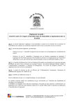
PACKAGE CONTENTS
Unpack your fan and check the contents. You
should have the following items:
a.
b.
c.
d.
e.
f.
g.
h.
~e
Hanger bracket assembly
Ball / down rod assembly
Fan motor assembly
Metal blade with cage (decorative* or
safety**) or Wood blade
Receiver with 6 wire nuts
Transmitter+holder+2 mounting screws
Allen wrench
Package hardware
1) Mounting hardware:
wood screws (2), screws (2),
lock washers (2), washers (2),
star washers (2), wire nuts (3)
*If blade is metal and accompanied by safety
cage (see Diagram d-i): To reduce the risk of
injury to persons, install fan so that blade are
at least 7.0 Ft. above the floor in the US and
8.3 Ft./2.5 M above the floor in Canada.
d-i
**If blade is metal and accompanied by
decorative
cage (See Diagram d-ii) or
unguarded wooden blade (See Diagram d-iii):
To reduce the risk of injury to persons, install
fan so that blade is at least 10.0 Ft. above the
floor in the US and 10.0 Ft./3.05 M above the
floor in Canada.
~
1
~.
~-iii
READ AND SAVE THESE SAFETY AND INSTAllATION
INSTRUCTIONS.
Consult a licensed electrician if unsure of any point below mentioned.
DANGERIW ARN ING/CA UTION
1. High voltage and moving parts around motors and motor driven equipment can cause serious
or fatal injuries. Always disconnect power source at main switch before wiring, servicing or
cleaning unit. Do not rely on fan control device to prevent unexpected start-up or electrical
shock. In addition, power supply must have fuses or circuit breakers for short circuit protection.
2. All electrical wiring must conform to national and local electrical codes such as: NEC, OSHA,
etc.
3. Fan should be secure in its electrical grounding to avoid possible electrical shock.
4. Fan should not be used in any wet or hazardous location defined by article 500 of the NEC. In
addition, its ambient temperature should not exceed 104 degrees Fahrenheit.
5. Power supply should conform to voltage rating of 120V.
6.
Before applying power, visually re-inspect the installation. Make sure that all guards and
protective devices are securely in place and all visible screws and bolts are tightened.
7. Warning: to reduce the risk of fire, electrical shock or personal injury, mount hanging bracket to
outlet box marked "Acceptable for fan support and a hanging weight of 45 Lbs." Do not mount
fan to sheet rock or drywall type materials and use only the screws provided with the outlet box.
8. Caution: to reduce the risk of injury to persons, install fan so that bottom edges of fan blades are
to be:
**In Canada, to satisfy CSA requirements: at least 8.3 Ft/2.5 M above the floor and all objects in
room if safety cages are utilized. 10,0 Ft if safety cages are not utilized.
**In the US, to satisfy UL requirements: at least 7.0 Ft above the floor and all objects in room if
safety cages are utilized. 10.0 Ft. if safety cages are not utilized.
9. To reduce the risk of personal injury, do not bend blades or any other part of fan when cleaning.
Do not insert foreign objects in between rotating fan blades or in space surrounding entire
rotating fan unit. Fan must be turned off at power at supply source before installation, cleaning
or servicing.
10. Instructions for Supply Connections: Conductor of a fan identified as grounded conductor
to be connected to a grounded conductor of a power supply, conductor of fan identified as
ungrounded conductor to be connected to an ungrounded conductor of a power supply,
conductor of fan identified for equipment grounding to be connected to an equipmentgrounding conductor. After making the wire connections in junction box, the splices should be
turned upward and pushed carefully into the outlet box. The wires should be spread apart with
the grounded conductor and the fan-grounding conductor on one side of the junction box and
the ungrounded conductor on the other side of the outlet box. Be sure that all wiring
connections are properly insulated from each other and any surrounding metal parts. For
safety and best operating results, we recommend that you have a qualified electrician
assemble and install your fan.
2
11. To reduce the risk of personal injury, install the supplementary mounting means and use only
the hardware provided with the fan.
12. Warning: TO REDUCE THE RISKS OF FIRE, ELECTRIC
PERSONS, OBSERVE THE FOllOWING:
A. Use this unit only in the manner intended by the manufacturer.
contact the manufacturer.
SHOCK
OR INJURY TO
If you have any questions,
B. Before installing, servicing or cleaning unit, switch power off at service panel and lock
service panel to prevent power from being switched on accidentally.
13. Warning: To reduce the risk of fire, electrical shock or personal injury, mount to outlet box
marked acceptable for fan support and use screws provided with outlet box.
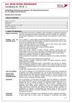
JUNCTION BOX MOUNTING
OPTIONS
Your new ceiling fan will require a grounded
electrical supply line of 120 volts AC, 60 Hz
circuit. The outlet box must be securely
anchored and capable of withstanding a load
of at least 45 Ibs.
Figure 1
Figures 1,2 and 3 are examples of different
ways to mount the outlet box.
Note: You may need a longer down rod to
maintain
proper blade clearance
when
installing on a steep, sloped ceiling. (Fig. 3)
To hang your fan where there is an existing
fixture but no ceiling joist, you may need an
installation hanger bar as shown in Fig. 4.
Figure 2
ANGLED CEILING
MAXIMUM 24° ANGLE
_Ceiling
hanger
bracket
Recesse
outlet box
Figure 3
~ s.o;n/'i
Outlet box
Figure 4
3
MOUNTING/INSTALLATION
OF THE FAN
i\1~.:.'
! iVC-~:~~ne~
•
bracket
~,\~::!
Before touching a screw driver thoroughly
read these instructions.
•
Warning/Caution: Before installing fan, turn
off power at service panel and check all visible
screws and bolts for tightness.
)~ceiling canopy
(~+---canopy
cover
Figure 5
1. Remove the decorative canopy bottom
cover from the canopy by turning the cover
counter clockwise. (Fig. 5)
2. Remove the hanger bracket from the canopy
by removing the 1 of 2 screws from the bottom of
the hanger bracket and loosening the other one a
half turn from the screw head. Next, turn the
canopy counter clockwise to removing the
hanger bracket from the canopy. (Fig, 5)
120VWires
Figure 6
3. Secure the hanger bracket to the ceiling
outlet box using screws and washers included
with your outlet box. (Fig. 6)
.--Cross
~
4. Remove hanger ball from down rod
assembly by loosening set screws, removing
the cross pin and sliding ball off rod. (Fig. 7)
pin
..
Hanger ....-..~
ball
~
SA. Metal Blade Head and Decorative Cage:
If your fan is one with a metal blade head and
decorative cage, remove protective plastic
sleeve from the motor shaft, and then attach
the metal blade head and cage. The Atlas
medallion
should be oriented
correctly.
Handle your blade head carefully otherwise
you will bend the blade irons and cause your
fan to vibrate when in use. Caution: The set
screw in the blade head hub must be
counter-sunk
into the bore-hole
on the
flattened side of the motor shaft - or else the
blade head may disengage from the motor
shaft during operation.
5B. Metal Blade Head and Safety Cage: If
your fan is one with a metal blade head and
safety cage, remove protective plastic sleeve
from the motor shaft, then and attach the back
side of the safety cage. Next, attach the blade
head. Handle your blade head carefully
otherwise you will bend the blade irons and
cause your fan to vibrate when in use. Finally
attach the front side of the cage with Atlas
medallion oriented correctly. Caution: The set
screw in the blade hub must be counter-sunk
into the bore-hole on the flattened side of the
motor shaft - or else the blade head may
disengage
from the motor shaft during
operation.
=o='!:
~
fl~"rnw
~
Downrod
Figure 7
Allen set screws
/
--------------1.-
Figure 8
4
~~:~Ch
5 C. Wooden Blade Head: If your fan is one
with wooden blade head, attach your blades as
the last step in the assembly process. Do not
attach them now. Attach them in step No.: 9.
Handle your blade head carefully otherwise you
will bend the blade irons and cause your fan to
vibrate when in use.
6. Loosen the two set screws from the top
coupling of the motor assembly. (Fig. 8)
Figure 9
7. Carefully feed the fan wires up through the
down rod. Thread the down rod into the
coupling then tighten the set screws using the
Allen wrench.(Flg. 8) Carefully reinstall hanger
ball onto rod being sure that cross pin is in
correct position, the set screw on hanger ball is
tight and wires are not twisted.
(~)
8. Now lift the motor assembly into position and
place the hanger ball into the hanger bracket.
Rotate until the "Check Tab" has dropped into
the "Registration Slot" and seats firmly. The
entire motor assembly should not rotate if this
is done correctly.
'.
9. Remove protective plastic sleeve from the
motor shaft and attach your wooden blades.
Ignore this step if you have metal blades, as
tfley should already have been installed. Make
sure that the set screw in the blade hub is
counter-sunk into the bore-hole into the shaft of
the motor.
.'
Figure 10
MAKING THE ELECTRICAL
CONNECTIONS
Warning: The power should have already
been disconnected. Follow the steps below to
connect the fan to your household wiring. Use
the wire nuts supplied with your fan. Secure
the wire nuts with electrical tape. Make sure
there are no loose strands or connections.
NOTE: The Hand Held Remote Control units
included with your ceiling fan are equipped
with 16 code combinations to prevent possible
interference from or to other remote units. The
frequency switches on your Receiver and
Transmitter units have been preset at the
factory. Please re-check to make sure the
switches on both units are set to the same
positions. The frequency settings should be
changed only in case of interference or if a
second or more remote controlled ceiling fans
are installed in the same room. Any code
combination will operate the ceiling fan and
light as long as the Receiver and Transmitter
units are set to the same codes (Fig. 10)
1. Insert Receiver into Hanger Bracket with
the flat side of the Receiver facing the ceiling.
(Fig. 11)
Figure 11
5
2. Motor to Receiver Electrical Connections:
OUTLET BOX
A. Connect the WHITE wire from the fan to the
WHITE wire marked "TO MOTOR N" from the
Receiver.
-+
WHITE (NEUTRAL)
BLACK (HOT)
B. Connect the BLACK wire from the fan to the
BLACK wire marked "TO MOTOR L" from the
Receiver.
RECEIVER
-+
GREEN OR BARE
COPPER (GROUND)
WHITE ("AC IN N")
J.~_~
Vln-iITE("TO MOTOR N")
C. Connect the BLUE wire from the fan to the
BLUE wire marked "oscillation" from the Receiver.
Proceed to secure all wire connections with the
plastic wire nuts provided. (Fig. 12)
BLUE (OSCILLATION)
+-GROUND-{3 GROUND WIRES
(GREEN) ON CEILING FAN)
BLUE (OSCILLATION)
Note: Fan must be installed from a maximum
distance of 40 feet from the transmitting unit for
proper signal transmission between the transmitting
unit and the fan's receiving unit.
3. Receiver
Connections:
to
House
Supply
Wires
BLACK (MOTOR)
WHITE (NEUTRAL)
Electrical
A. Connect the WHITE wire (Neutral) from the
outlet box to the WHITE wire marked "AC in N"
from the receiver.
B. Connect the BLACK wire (Hot) from the outlet
box to the BLACK wire marked "AC in L" from the
receiver. Secure all wire connections with the
plastic wire nuts provided. (Fig. 12)
4. If your outlet box has a GROUND wire (Green or
Bare Copper) connect this wire to the Hanger Ball
and Hanger Bracket Ground wires. If your outlet
box does not have a Ground Wire, then connect
the Hanger Ball and Hanger Bracket Ground Wires
together. Secure wire connection with the plastic
wire nut provided. (Fig. 12)
Figure 12
OUtietbox_[
5. Tuck connections neatly into ceiling outlet box.
Hanger
bracket
6. Slide the canopy up to hanger bracket and place
the key hole on the canopy over the screw on the
hanger bracket, turn canopy until it locks in place at
the narrow section of the key holes. (Fig. 13)
Screws
7. Align the circular hole on canopy with the
remaining hole on the hanger bracket, secure by
tightening the two set screws. Note: Adjust the
canopy screws as necessary until the canopy and
canopy cover are snug.
Warning: Make sure tab at bottom
bracket is properly seated in groove of
before attaching canopy to bracket.
properly seat tab in groove could cause
electrical wiring.
.11
...
,
....
1
4b~canopy
of hanger
hanger ball
Failure to
damage to
Figure 13
6
cover
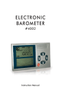
OPERATING THE REMOTE
CONTROL
Install12V
MN21/A23 battery (included).
To prevent damage to transmitter, remove the
battery if not used for long periods. (Fig. 14)
Restore Power to Ceiling Fan.
A. H, M, L Buttons:
These buttons are used to set the fan speeds
as follows;
L: Low Speed
M: Medium Speed
H: High Speed
Figure 14
B. OFF Button:
This button turns the fan off.
C. ACCESSORY Button:
This button is used to control the oscillating
operation.
Figure 15
7
,
!
CARE OF AND TROUBLESHOOTING
YOUR FAN
1. Check hardware bi-yearly. Because of the fan's natural movement some connections may
become loose over time. Check the support connections, brackets and blade attachments
twice a year. Make sure they are secure. It is not necessary to remove fan from the wall.
2. Clean your fan periodically. This will help to help maintain its new appearance over the
years. Use only a lightly water-moistened, lint free cloth to avoid scratching the finish. Plated
finishes are sealed with lacquer to minimize discoloration or tarnishing. Do not let rain or
running water to come in contact with the fan. Rain or running water could damage the motor,
wood blades or possibly cause an electrical shock .
. 3. There is no need to oil your fan. The motor has permanently lubricated bearings.
4. Fan makes a vibration noise. Check to see that all screws are tight in the fan cage
connection to the motor face plate.
5. Fan vibrates or makes grinding noise as blades rotate. Uninstall and reinstall the blades.
Make sure that your fan head's set screw is counter-sunk into the bore hole in the flat part of
the motor shaft. Be careful that the blade brackets themselves are not bent in this process. Do
not operate your fan if it continues to vibrate. Contact your Atlas Fan Co purveyor if the
re-installation of the blades does not resolve the problem.
8