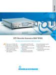
1
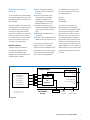
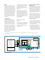
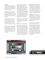
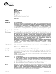
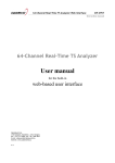
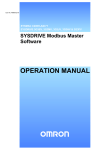
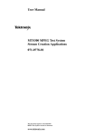
Data sheet Version 02.00 04.00 Digital Video Measurement System ¸DVM 400 Monitoring, analysis, recording and generation of MPEG-2 transport streams ◆ Transport stream monitoring – Monitoring of all TR 101290 first, second and third priority parameters (except buffer) – Data rate monitoring – Single frequency network monitoring – Data rates up to 214 Mbit/s – Event-controlled transport stream capture function – User-definable alarm relays – Flexible definition of monitoring parameters ◆ Transport stream analysis – Data rates – PCR and PTS analysis – Table/packet interpreter – Data broadcast analysis ◆ Transport stream generation, recording and replaying – Bit rates up to 214 Mbit/s – Memory up to 120 Gbyte – Extensive test signal library – Transport stream generation software ◆ Operating features – Event Navigator – Wizard ◆ Large color display ◆ USB interfaces on front and rear panels ◆ Ethernet interface (100 Mbit/s) ◆ Simple remote control ◆ System integration via SNMP for monitoring applications ◆ Flexible option management February July 2005 2006 General The ¸DVM 400 is a highly compact, portable MPEG-2 platform that offers a wealth of test, analysis and monitoring functions for digital TV. Users require neither a laptop nor an external monitor to operate the system since it comes equipped with an integrated, highresolution color display. The system is operated by means of its keys and rotary knob, or via the supplied USB mouse. An external monitor and keyboard can be connected. Versatile options ensure that customer requirements are optimally satisfied. Functions can usually be added simply by installing a software key. The ¸DVM 400 includes a powerful computer platform with various interfaces and space for three plug-in cards. A broadband recorder and generator board can be installed in the first slot. A fast analyzer board as is used in other systems of the ¸DVM family is a vailable for the second slot. This board allows parallel monitoring of up to four transport streams. Since both boards function independently of each other, the ¸DVM 400 can be configured either as a pure recorder and generator or as a pure analyzer. If both boards are installed, special features are available. For example, a recorded signal can be sent directly within the system to the analyzer board for later analysis. Or, if a signal is monitored, the analyzer board can directly trigger the recorder and generator board to perform event-driven recording. Various test signals are available for the recorder and generator board. By using the Stream CombinerTM software, users can generate their own transport streams on the ¸DVM 400. Like the ¸DVM 100, the ¸DVM 400 can be expanded by the ¸DVM 120 to monitor more than four transport streams; parallel monitoring of up to 20 transport streams is thus possible via the GUI of the ¸DVM 400 (two ¸DVM 120 plus options are required). Both boards support a variety of functions, some of which are optionally available. The analyzer board allows not only transport stream monitoring, but also the analysis of data rates, PCR and PTS values, the interpretation of tables and packets plus the analysis of diverse data services. Recorder and generator board options Analyzer board options 0 to 3 possible ¸DVM400-B4 ¸DV-DVBH ¸DV-ASC 2) ¸DVM-K1 ¸DVM-K2 Upgrade TS Recorder DVB-H Stream Library Advanced Stream Combiner Additional TS Input TS Capture ¸DVM400-B3 ¸DV-TCM ¸DV-HDTV ¸DVM-K11 ¸DVM-K12 ¸DV-ESA Upgrade TS Recorder Test Card M Streams HDTV Sequences Data Broadcast Analysis Template Monitoring Video Elementary Stream Analyzer ¸DVM400 Hardware option Software option ¸DVM400-B2 ¸DVM400-B1 1) TS Generator (GTS format only) Analyzer 1) Contains In-Depth Analysis ¸DVM-K10 2) Two models: model 02 for parallel interface model 03 for USB interface The ¸DVM 400 functions and options Digital Video Measurement System ¸DVM 400 Monitoring and analysis functions The figure below shows a block diagram of the analyzer board that is used for the monitoring and analysis functions of the ¸DVM 400. Up to four transport streams can be monitored in parallel. One transport stream can be monitored with the analyzer option, another three with one ¸DVM-K1 option each. In addition to the monitoring functions, numerous analysis functions are available. Analysis can be performed on one of the transport streams at the same time it is being monitored. Monitoring functions Transport streams are monitored in accordance with Measurement Guidelines TR 101290. Well over 100 parameters are monitored on each transport stream, including: ◆ All first, second and third priority parameters (with the exception of 3.3, buffer) ◆ Bit rates of all transport stream elements (different calculation methods in accordance with TR 101290 can be selected (MGB1, MGB2 and MGB5 with τ = 5 s)) ◆ Availability and contents of the megaframe initialization packet (MIP), used in single frequency networks (SFN) ◆ Modification of conditional access information ◆ Transport stream modifications (TS ID, addition or omission of elements, etc) result display, the user assigns each measurement parameter to one of the three following classes: ◆ Alarm ◆ Warning ◆ Information If an (error) event is detected, it is displayed along with its associated class. All events are compiled in a report that can fast and easily be sorted and filtered on the basis of diverse criteria. Moreover, there is an error counter for the individual parameters, providing a quick summary of the frequency of individual errors. The data and table refresh rates are clearly presented by means of graphical displays. The use of symbols to indicate different classes of errors makes it possible to quickly determine the current status. The limit values of all measurement parameters can be set. Individual parameters can be excluded from monitoring so that no unnecessary messages are generated for known or accepted errors. To obtain a straightforward Analyzer board 1 2 3 4 ASI/310M IN ASI/310M IN or loop-through of 1 ASI/310M IN ASI/310M IN or loop-through of 3 Internal TS IN recorder and generator board 1 2 3 RAM Internal trigger OUT recorder and generator board TS1) processor 4 SPI IN 1) Max. 4 TS simultaneously (option required for >1 TS) ¸DVM400 base unit External alarm lines External 10 MHz reference Analyzer board Digital Video Measurement System ¸DVM 400 Event navigator As a special feature, the ¸DVM 400 supports filter functions for the report entries which can be easily selected by clicking the right mouse button. It is thus possible to quickly detect: ◆ All entries for a PID (e.g. all entries for PID 100 (e.g. video)) ◆ All entries of the same type (e.g. all entries for an incorrect PMT repetition period) ◆ All entries for a PID of the same type Moreover, all entries can be filtered on the basis of their classification (alarm, warning and information). Analysis functions Each analysis function can be performed at the same time transport streams are being monitored. In-depth analysis PCR jitter: For comprehensive measurement of PCR jitter; selection of one of the two measurements “Overall” or “Accuracy”; setting of the filters used (MGF1 to MGF3) also for monitoring; measurement and filter characteristics as defined in TR 101290. Application example for the event navigator SI/PSI table interpreter: Detects a corresponding section in the TS and interprets its contents. PES header interpreter: Lists all header elements of a selected PES and interprets their contents. TS packet interpreter: Displays a transport stream packet in hex format and simultaneously as an interpreted list of contents for the header and adaptation field. Header map: Provides an overview of the packet distribution of individual elementary streams; displays the first four bytes of each transport stream packet in hex format. PCR distance: Graphical representation of the distance between individual PCR values of a program. PTS/PCR difference: Graphical representation of the difference between PTS and PCR. PTS distance: Graphical representation of the distance between individual PTS values of a program. All measured PCR and PTS values are displayed as traces. Up to one hour of data can be displayed. Zooming within the display is no problem. The figure on the right shows an example of a PCR measurement. PCR measurement Digital Video Measurement System ¸DVM 400 Data broadcast analysis A wide scope of analysis functions is available for data broadcast applications. The ¸DVM400-B1 base option alone provides the following functionalities. All transmission techniques and related applications listed below are recognized and entered in the transport stream elements list under the appropriate designation: ◆ DVB object carousel, e.g. for downloading of MHP applications ◆ DVB data carousel, e.g. for system software updates (SSU) ◆ Multiprotocol encapsulation (MPE), e.g. for IP data transmission ◆ Data streaming, e.g. for teletext, subtitles, VPS, WSS and transmission of personal data ◆ Data piping, e.g. for transmission of personal data The following tables are also listed: ◆ Application information table AIT (MHP) ◆ IP/MAC notification table INT (IP data via MPE) ◆ System software update notification table UNT (SSU) The data broadcast analysis option significantly enhances the scope of functionalities. Another view can be selected in the GUI. The corresponding section is highlighted in red in the figure below. The bit rates of a data service can also be measured by means of the associated PID. In-depth analysis functions: ◆ Interpretation of related tables (AIT, INT and UNT) ◆ Interpretation of PES headers (data streaming) ◆ Interpretation of TS packets (all profiles) Topic selection “Protocol“ Indication of data transmission profile visualization of transmitted element structure Results/information on “Protocol” related to selected topic Operation buttons “Content“ visualization of content structure Information on “Content” elements Data broadcast analysis button Data broadcoast analysis view Digital Video Measurement System ¸DVM 400 The two views “Protocol“ and “Content“ are especially useful for more complex data transmission methods such as MPE and object and data carousel. The figure below shows an example of an object carousel. These two views have the following functions: ◆ “Protocol”: displays the transmission element structure – Example: data/object carousel: DSI, DIIs, DDBs organized in groups and modules – Example: IP data via MPE: number of sections per MAC address ◆ “Content”: displays the content structure – Example: IP data via MPE: MAC addresses found – Example: object carousel: service gateway, directories, subdirectories, files, references to streams and events A separate section provides detailed information on the “Content” elements (e.g. related transmission elements), see page 5. Overview of data broadcoast measurements Data piping Overview Interpreter display of descriptors used and name of tables c ontaining the descriptors TS header Raw data TS packet contents Timing measurements ES bit rate repetition time of payload unit start indicators Data streaming Overview Interpreter display of descriptors used and name of tables c ontaining the descriptors PES header Raw data PES packet contents Timing measurements PES bit rate repetition time of PES header MPE Overview “Protocol“ and “Content“ display Interpreter display of descriptors used and name of tables c ontaining the descriptors section Raw data section contents Timing measurements bit rate of selected section repetition time of selected section Data carousel/object carousel Overview Digital Video Measurement System ¸DVM 400 Interpreter display of descriptors used and name of tables c ontaining the descriptors section (DSI, DII and DDB header) Raw data DDB section contents Timing measurements bit rate of selected module, DSI, DII section repetition time of selected DII, DSI section loading time of selected module Wizard This powerful feature makes the use of the different analysis tools highly effective and easy. Once a transport stream element has been selected, the wizard suggests all analyses and measurement result views that are useful for this element, allowing fast and detailed analysis especially when an error has been detected. The wizard is ideal for less experienced users because it enables them to easily obtain correct measurement results. TS capture function This option (¸DVM-K2) makes it possible to continuously buffer up to 384 Mbyte1) of transport stream data in RAM. An event can trigger backup of transport stream data to the system hard disk. This event may be an error detected by the analyzer board or when the user starts recording. This function can be configured in such a way that it waits for a new event once the data has been saved. The stored files are automatically numbered. 1) Generation of seamless and endless transport streams The recorder and generator board allows the generation of endless and seamless transport streams. For this purpose, the TS generator base option contains an extensive collection of transport streams in the Rohde & Schwarz GTS format. This function can also be started for all four transport streams of an analyzer board simultaneously. In this case, 96 Mbyte are available for each transport stream. The ¸DVM-K2 option is designed specifically for storing incorrect transport stream sections during analysis or transport stream monitoring. If a large amount of data is involved, the recorder and generator option can be used to record and replay it. The transport streams generated from the RAM meet all requirements specified in the section “How to generate a transport stream in a seamless endless loop” (page 9). The following characteristics are additionally provided: Recorder and generator functions ◆ Jitter of the PCR values (waveform, frequency and amplitude can be set) ◆ Selectable data rate (up to 214 Mbit/s by inserting null packets) ◆ Transport stream generation in GTS format with user-specific contents (both elementary stream contents as well as PSI/SI/PSIP contents (option Stream CombinerTM ¸DVG-B1) The figure below shows a block diagram of the recorder and generator board used to record, replay and generate transport streams. For systems delivered as of May 2004 (systems delivered prior to this date feature 128 Mbyte (32 Mbyte with four transport streams)); expansion possible through Rohde & Schwarz Service. Recorder and generator board 1 ASI/310M OUT1 1 2 ASI/310M OUT2 2 3 ASI/310M IN1 3 4 Loop-through of 3 4 5 ASI/310M IN2 5 6 Loop-through of 5 6 analyzer board S1 RAM HD1 Internal S2 HD2 trigger IN analyzer board S1: Selector: record or play/generate S2: Input selector Internal TS OUT SPI IN ¸DVM400 base unit SPI OUT External trigger IN External 10 MHz reference Recorder and generator board Digital Video Measurement System ¸DVM 400 Test signals The TS generator option comes with a variety of different preconfigured MPEG-2 transport streams that are compliant with the ATSC and DVB standards and can be accessed at a keystroke. These transport streams consist of several elementary streams and contain video, audio and other data (e.g. teletext or PRBS). Video streams with different data rates, formats, frequencies and contents are available. The signal set comprises sequences with moving picture contents as well as static test patterns. The test patterns include color bars, zone plate, CCIR17/18/331, ITS1 to ITS4, etc, and the Rohde & Schwarz codec test pattern. Due to integrated test lines in the upper and lower picture area of this test pattern, the codec signal can be utilized to measure the analog outputs of a set-top box (or IRDs) within a few seconds by using a suitable video analyzer such as the ¸VSA. In addition, integrated moving picture elements allow the function of the decoder to be checked visually for any problems. Audio data streams with different sampling rates, encoded in line with MPEG-1 layer 2 or Dolby AC-3, contain the accompanying sound for the video sequences as well as special audio test signals. Of course, the transport streams include all program information, service and system tables (PSIP or SI) required by MPEG-2 and ATSC or DVB as stipulated by the selected standard. Further options enable HDTV signals and other special test signals to be added to this large collection (see HDTV and Test Card M). HDTV: The ¸DV-HDTV option provides an extensive transport stream library containing high-resolution video signals. To generate individual transport streams, this option also includes these video signals in the form of elementary streams. The transport stream data is already stored in the base unit. The function can be enabled by installing a software key. A separate data sheet is available for this option (PD 0757.6979). Test Card M: The ¸DV-TCM option supports the replay of a special collection of transport streams developed by the Snell & Wilcox company and referred to as Test Card M. The transport stream data is already stored in the base unit. The function can be enabled by installing a software key. A separate data sheet is available for this option (PD 0757.7369). Recording: Transport streams can be recorded at data rates up to 214 Mbit/s. Exchanging transport streams with other systems is no problem since the stored files contain the transport stream packets in consecutive order and without additional headers. As a special SPI feature, the recorder and generator board also allows interface-specific data to be recorded simultaneously with transport stream data (8 bits). It records the bits for signaling the start of the packet (PSYNC) and for the validity of the data (DVALID), thus storing a total of 10 bits for 8 data bits. Since recording is transparent, also nonDTV-compliant signals and even signals of other applications can be recorded via the interfaces. Trigger Pretrigger Transport stream Sample signal: universal 4:3 Rohde & Schwarz codec test pattern Digital Video Measurement System ¸DVM 400 The length of the pre- and post-trigger can be set on the ¸DVM The recording of all signals can be controlled via the external trigger input of the ¸DVM 400 base unit or the analyzer board. For this purpose, the applied signal is continuously buffered. If a trigger event occurs, the signal sections both following the event (post-trigger) and preceding the event (pretrigger) can be stored. The length of the post- and pretrigger can be set. It is thus possible to determine where in the stored signal the event is located. This function is particularly important for error analysis. Replay of recorded signals Replayed signals are applied to all external transport stream interfaces simultaneously (ASI/310M OUT 1, 2 and SPI OUT). Signals 10 bits in width can be replayed only via the SPI interface. For optional analysis, the transport stream signals are internally played to the analyzer board. The signals are replayed in an endless loop in such a way that the transition from the end to the beginning of the recording always coincides with the packet. Correct decoding of the video and audio sequences in the replayed transport stream is ensured only if the original data rate of the recording is used. For this reason, the data rate of transport streams is automatically determined on the basis of the present PCR values. Irrespective of this automatic recognition, the data rate can be set by the user (up to 214 Mbit/s). Furthermore, the interfaces can be configured for playback. Post-trigger M 400 for triggered recording t The user can thus choose between the “packet” and “continuous” operating modes for the ASI interface. This feature is especially crucial for router testing. For the SPI interface, signaling can be set via the “data valid” circuit. This flexibility allows versatile tests to be performed and offers maximum compatibility with other instruments. Bit rates and memory In the default state, transport streams (GTS format) are generated from RAM. They can be generated by inserting null packets at data rates up to 214 Mbit/s. The ¸DVM 400-B3 option additionally supports recording and replaying in TRP format at data rates up to 90 Mbit/s (TRP format). A special feature is the packet-exact cutting function for recorded transport streams. It is thus possible to automatically replay specific sections of long recordings in a loop or store them to a hard disk for further analysis or simple transfer to other instruments. The ¸DVM 400-B4 option permits recording and replaying at up to 214 Mbit/s. Furthermore, this option expands the available storage capacity for transport stream data from min. 60 Gbyte to min. 120 Gbyte. Stream Combiner™ Stream Combiner™ enables easy expansion of the transport stream library that is supplied. New transport streams can be quickly generated from supplied or recorded elementary streams. Used as an offline multiplexer, Stream Combiner™ automatically integrates all program information, service and system tables (PSI/SI/PSIP) required in accordance with MPEG-2 and the selected standard (ATSC or DVB). How to generate a transport stream in a seamless endless loop Transport streams can be seamlessly generated in an endless loop (GTS mode), provided the following two conditions are met: In addition, Stream Combiner™ allows the user to edit, add to or remove all table contents – even in violation of standards – in order to generate test signals for specialized tasks. The transport stream files can be generated in GTS or TRP format. A separate data sheet is available for this option (PD 0757.3611). ◆ All time stamps (PCR, PTS and DTS values and entries in the TDT, TOT and STT tables) in the transport stream must be updated in realtime ◆ The individual elementary streams must be calculated or cut in such a way that they end with a complete GOP (video) or an entire frame (audio) so that no errors occur in the decoder; plus, they must be calculated in such a way that the average buffer fill state remains constant during a loop period to avoid any buffer underflow or overflow during continuous replay in an endless loop If these conditions are met, the transport stream appears to be continuously generated in realtime directly from a multiplexer and a number of encoders connected to it, although the video, audio and data contents are repeated. Digital Video Measurement System ¸DVM 400 Overview of options and functions Base functions Base unit ¸DVM 400 computer platform – motherboard – hard disk – RAM – Windows XP Embedded color display loudspeaker keys and rotary knob USB wheel mouse 3 slots 2 SPI connectors (input and output) 10 MHz reference input 12 alarm lines 1) trigger input Ethernet interface 4 × USB connectors expansion connector for ¸DVM 120 Analyzer ¸DVM 400-B1 Additional TS Input ¸DVM-K1 TS Capture ¸DVM-K2 analyzer board (4 ASI/310M connectors) unblocking function for one transport stream (TS Input) monitoring functions analysis functions in-depth analysis event navigator wizard unblocking function for parallel monitoring of one additional transport stream storage and recording of transport stream sections Data Broadcast Analysis ¸DVM-K11 analysis of data broadcast services TS Generator (GTS format only) ¸DVM 400-B2 Upgrade TS Recorder TRP 90 Mbit/s (option ¸DVM400-B2 required) ¸DVM 400-B3 Upgrade TS Recorder TRP 214 Mbit/s (options ¸DVM400-B2 and ¸DVM400-B3 required) Test Card M Streams ¸DVM 400-B4 generator board (ASI/310M connectors) support of GTS mode transport stream generation test signal library hard disk recording, replaying bit rates up to 90 Mbit/s (hard disk) and 214 Mbit/s (memory) bit rates up to 214 Mbit/s (hard disk and memory) doubling of hard disk memory (additional hard disk) ¸DV-TCM additional test signals HDTV Sequences ¸DV-HDTV additional test signals Stream Combiner™ ¸DVG-B1 offline TS multiplexer software elementary stream library Analyzer functions Recorder and generator functions 1) If the trigger input is used for the TS recorder, only 11 alarm lines are available. 10 Digital Video Measurement System ¸DVM 400 Abbreviations AIT ATSC BAT Application information table Advanced television systems committee Bouquet association table PAT Program association table PCR Program clock reference PES Packetized elementary stream BIOP Broadcast inter ORB protocol PID Packet identification CAT Conditional access table PIT Program identification table CETT Channel extended text table PMT Program map table CVCT Cable virtual channel table PSI Program specific information DDB Download data block PSIP Program and system information protocol DIT Discontinuity information table PT Private table DSI Download server initiate PTS Presentation time stamp DII Download info indication RRT Rating region table DSM-CC Digital storage media – command and control RST Running status table DTS Decoding time table SDI Serial digital interface DVB Digital video broadcast SDT Service description table EIT Event information table SDTI Serial digital transport stream interface EPG Electronic program guide SI Service information ETT Extended text table SIT Selection information table GOP Group of picture ST Stuffing table HDTV High definition television SSU System software update ID Identifier STB Set-top box INT IP/MAC notification table STT System time table IP Internet protocol TDT Time and date table IRD Integrated receiver decoder TOT Time offset table MAC Media access control TS Transport stream MGT Master guide table TVCT Terrestrial virtual channel table MHP Multimedia home platform UNT System software update notification table MIP Megaframe initialization packet VPS Video programming system MPEG Motion picture expert group WSS Wide screen signaling NIT Network information table ORB Object request broker Digital Video Measurement System ¸DVM 400 11 Specifications Base unit Analyzer board Signal inputs, MPEG-2 transport stream2) PC platform/controller Operating system RAM Windows XP Embedded, service pack 1 256 Mbyte System hard disk IDE hard disk Software only software approved by Rohde & Schwarz for the ¸DVM 400 2 × USB1.1 on both the front and rear panels USB interfaces Ethernet Remote control Control of local analyzer board External monitor Alarm relays Reference clock input 10/100 Mbit/s; RJ-45 10/100 Mbit/s; RJ-45 max. 5 analyzer boards up to 1600 × 1200 pixels, min. 1024 × 768 pixels required 15-pin D-sub female connector for SVGA or TFT monitor 12 1) with random event assignment; 15-pin D-sub female connector 10 MHz, 0.1 V to 2 V (rms) BNC female connector on rear panel of base unit for analyzer board and recorder and generator board Serial inputs Asynchronous serial interface Data rate Mode TS packets or Synchronous serial input Data rate TS packets Cable length Parallel input Synchronous parallel interface Level Maximum data rate across all inputs (max. 4) Loop-through outputs, MPEG-2 transport stream +5 °C to +40 °C Permissible temperature range +5 °C to +40 °C Storage temperature range –40 °C to +70 °C Power supply 5 Hz to 150 Hz, max. 2 g at 55 Hz, 55 Hz to 150 Hz, max. 0.5 g const., meets EN 60068-2-6, EN 61000-1 and MIL-T-28800D class 5 10 Hz to 300 Hz, acceleration 1.2 g (rms) 40 g shock spectrum, meets MIL-STD-810D and MIL-T-28800D class 3 and 5 95 % rel. humidity, cyclic test at +25 °C/+40 °C, meets EN 60068-2-30 meets EN 50081-1 and EN 50082-2 (EMC directive of EU) 100 V to 240 V/50 Hz to 60 Hz Dimensions (W × H × D) 375 mm × 176 mm × 285 mm Shock Climatic resistance Electromagnetic compatibility Weight With analyzer With recorder and generator With analyzer and recorder and generator SPI, according to EN 50083-9 25-pin female connector on front panel of base unit LVDS 214 Mbit/s3) inputs 2 and 4 selectable as loopthrough outputs for input 1 and input 3 Signal inputs, MPEG-2 transport stream Operating temperature range Vibration, random (SSI, in line with SMPTE 310-M) 19.392658 Mbit/s 188 bytes max. 180 m Recorder and generator board General data Mechanical resistance Vibration, sinusoidal 4 inputs, each with BNC female connector (75 Ω) selectable, (ASI, in line with DVB-A010) 270 Mbit/s continuous or packet 188/204/208 bytes Serial inputs Asynchronous serial interface Data rate Mode TS packets or Synchronous serial input Data rate TS packets Cable length Parallel input Synchronous parallel interface Level Clock Mode 2 inputs, each with BNC female connector (75 Ω) selectable, ASI, in line with DVB-A010 270 Mbit/s continuous or packet 188/204/208 bytes SSI, in line with SMPTE 310-M 19.392658 Mbit/s 188 bytes max. 180 m SPI, in line with EN 50083-9 25-pin female connector on front panel of base unit LVDS 84.375 kHz to 20 MHz TRP, 8 bit (8 bit data) T10, 10 bit (8 bit data, 1 bit data valid, 1 bit packet sync) 7.8 kg 7.6 kg 8.4 kg 1) If the trigger input is used for the TS recorder, only 11 alarm lines are available. The number of inputs that can be used simultaneously depends on the number of installed ¸DVM-K1 options. 3) Content-dependent. 2) Digital Video Measurement System ¸DVM 400 12 Signal outputs, MPEG-2 transport stream Serial outputs Asynchronous serial interface Data rate Mode TS packets or Synchronous serial input Data rate TS packets Cable length Parallel output Synchronous parallel interface 2 outputs, each with BNC female connector (75 Ω) selectable, ASI, in line with DVB-A010 270 Mbit/s continuous or packet 188/204/208 bytes SSI, in line with SMPTE 310-M 19.392658 Mbit/s 188 bytes max. 180 m SPI, in line with EN 50083-9 25-pin female connector on rear panel of base unit Level LVDS Clock 84.375 kHz to 20 MHz Mode TRP, 8 bit (8 bit data) 1 bit packet sync automatically generated and 1 bit data valid configurable: exactly 188 bytes active constantly active with packet length of 204 or 208 bytes T10, 10 bit (8 bit data, 1 bit data valid, 1 bit packet sync) Loop-through outputs, MPEG-2 transport stream 2 serial loop-through outputs Generator (TRP format) and recorder 90 Mbit/s With option ¸DVM 400-B3 Interface inputs and outputs 8 bit 10 bit Min. data rate Max. data rate Max. data volume Endless replay Generator (TRP format) and recorder 214 Mbit/s With options ¸DVM 400-B3 and ¸DVM 400-B4 Interface inputs and outputs 8 bit 10 bit Min. data rate Max. data rate Max. data volume Endless replay for recording and replaying signals of any content ASI, SPI and SSI SPI 675 kbit/s 214 Mbit/s from memory 90 Mbit/s from hard disk limited only by size of hard disk packet-exact cut at transition from end of file to beginning of file for recording and replaying signals of any content ASI, SPI and SSI SPI 675 kbit/s 214 Mbit/s from memory and hard disk limited only by size of hard disk packet-exact cut at transition from end of file to beginning of file ASI, in line with DVB-A010 or SSI, in line with SMPTE 310-M depending on signals at serial inputs Signal characteristics TS generator (GTS format) Interface outputs Length of transport stream packets ATSC DVB Sequence length Data rate Net data rate Data volume PCR jitter Form Frequency Amplitude Increment Signal set Systems for generating transport streams in line with ISO/ICE 1-13818 ASI, SPI and SS 188/208 bytes (selectable) 188/204 bytes (selectable) endless and seamless generation with repetition of video, audio and data contents 675 kbit/s to 214 Mbit/s (including null packets) max. 90 Mbit/s max. 80 Mbyte payload sine, rectangle and triangle 1 mHz to 100 kHz 0 ms to 1 ms 0.1 µs moving picture sequences and test patterns with test tones, for 625 and 525 lines DVB/ATSC Additional signals via options Digital Video Measurement System ¸DVM 400 13 Ordering information Designation Type Order No. Digital Video Measurement System ¸DVM 400 2085.1800.03 Analyzer ¸DVM 400-B1 2085.5505.02 Additional TS Input ¸DVM-K1 2085.5211.02 TS Capture1) ¸DVM-K2 2085.5234.02 Data Broadcast Analysis ¸DVM-K11 2085.5311.02 Analyzer options Recorder and generator options1) TS Generator (GTS format only) ¸DVM 400-B2 2085.5511.02 Upgrade TS Recorder up to 90 Mbit/s ¸DVM 400-B3 2085.5528.03 Upgrade TS Recorder up to 214 Mbit/s ¸DVM 400-B4 2085.5534.03 Test Card M Streams ¸DV-TCM 2085.7708.02 HDTV Sequences ¸DV-HDTV 2085.7650.02 Stream Combiner™ ¸DVG-B1 2068.9835.02 Recommended extras Documentation of Calibration Values ¸DVM-DCV Service Manual Available on request. More information at www.rohde-schwarz.com (search term: DVM400) Certified Quality System Certified Environmental System ISO 9001 ISO 14001 DQS REG. NO 1954 QM DQS REG. NO 1954 UM www.rohde-schwarz.com Europe: +49 1805 12 4242, [email protected] USA and Canada: 1-888-837-8772, [email protected] Asia: +65 65 130 488, [email protected] ¸ is a registered trademark of Rohde & Schwarz GmbH & Co. KG · Trade names are trademarks of the owners · Printed in Germany (Bi bb) PD 0758.0397.32 · ¸DVM 400 · Version 04.00 · July 2006 · Data without tolerance limits is not binding · Subject to change 1) 2082.0490.29 2085.1839.02