1
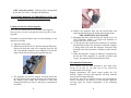
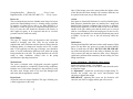
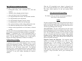
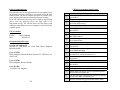
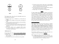
CONTENTS:
Safety:
•
1. Safety............................................................................... 2
2. Daystate Owners Club................................................... 3
legitimate target.
•
•
7. Trigger Adjustment – Mechanical 2 stage trigger ..... 8
8. MK3 CDT(a) Battery Replacement ........................... 10
9. MK3 CDT(a) Electronic Trigger Unit...................... .11
10. MK3 CDT(b) Electronic Trigger Unit..................... 12
Always treat your airgun as if it was loaded, even if you
know it’s not.
5. Loading the Daystate 10 shot magazine ...................... 5
6. Recommended Maintenance......................................... 6
Always check that your airgun is not loaded when you first
pick it up.
3. Filling your air rifle with compressed air ................... 3
4. Loading your rifle – Single Shot................................... 4
Never point your airgun at anyone or anything other than a
•
Never shoot on land where you do not have permission to
shoot.
•
Always use a safe, large backstop to catch your pellets- and
pay due attention to what’s behind it, should you miss.
•
Never leave your airgun unattended.
•
Always store your airgun and pellets separately and
11. MK3 CDT(b) Programming & Operation.............. 13
securely so that no unauthorised person can use them.
12. CDT(b) Battery Charging......................................... 13
•
13. Gun Operation and Programming........................... 14
General information.
14. Technical data ............................................................ 19
Congratulations on choosing a Daystate air rifle. Your rifle has
been made using the finest materials available and has been
precision made using CNC engineering technology. This rifle is
the culmination of Daystate’s involvement with pre-charged air
rifles and uses knowledge gained from manufacturing this type
of air rifle for nearly 30 years, making your Daystate one of the
most accurate and reliable rifles available today. The maximum
power output of your rifle has been factory set. In the UK It is
the owner’s responsibility to ensure that non-firearms licenced
rifles do not exceed the legal limit of 12ft./lbs. If you have to
leave your rifle for any length of time Daystate suggest that
some air is left in the reservoir, this will keep moisture at bay
15. Accessories for your Daystate rifle. ......................... 20
16. Pellet recommendations. ........................................... 23
17. CDT(b) Programming Quick Guide........................ 24
18.Telescopic Sight Fitting and Zeroing Instruction.... 26
19. Safe Shooting Ranges ................................................ 28
20. Daystate Warranty .................................................... 30
Know and abide by the laws relating to airguns.
2
and help to maintain the integrity of the seals. Spare parts are
available by contacting Daystate or your local agent and
ordering the relevant parts.
Daystate Owners Club
The official owner’s club can be found on the Internet at:
www.daystate.com. Log-on for all the latest information and
news.
WRITE YOUR RIFLE’S DETAILS HERE:
3) Fill to the charging pressure indicated on the side of the
breech and then close the feed valve. Allow a few seconds
for the pressure to ‘settle’ and then top up if required.
4) Open the bleed valve on the hose and gauge unit and bleed
off the air from the filler hose.
5) Remove the snap-on connector and replace the dust cap.
Loading your rifle – Single Shot
Remember to keep the muzzle of the air rifle pointing in a safe
direction at all times.
1) Apply the safety catch*.
2) Lift the cocking handle at the rear of the breech block and
pull all the way back.
Filling your air rifle with compressed air
1) Remove the dust cap from the front of the reservoir and
connect the female snap-on connector onto the inlet valve
whilst making sure that the outer sleeve is fully forward
and that the connection is secure.
2) Check that the bleed screw on the hose and gauge unit is
closed and slowly open the feed valve. Compressed air
will now fill the reservoir.
3
3) Check that the pellet is not damaged and place it in the
loading channel.
4) Push the cocking handle forward and make sure that the
handle is down.
THE AIR RIFLE IS NOW LOADED!
Disengage the safety catch and the rifle will now fire.
4
*CDT (electronic) models. With the safety catch pushed
up into the 'Fire' mode, a red light will illuminate.
TO PREVENT DAMAGE TO THE RIFLING, ONLY USE
SOFT METAL OR PLASTIC PELLETS
Loading the Daystate 10 shot magazine.
Note: The two countersunk screws located in the magazine
housing must be in place and tightened when using the 10 shot
magazine.
Remember to keep the muzzle of the air rifle pointing in a safe
direction at all times.
1) Apply the safety catch.
2) Rotate the breech bolt by 45o upwards and pull fully back.
Release the bolt and remove the magazine from the left
side. Note that the magazine can be adapted to fit from the
right or both sides by moving the magazine stop pin.
4) Replace the magazine back into the breech block and
return the bolt forward to the closed and locked position.
THE AIR RIFLE IS NOW LOADED
5) Disengage the safety catch and the rifle will now fire. On
CDT (electronic) models a red light will illuminate to
confirm the rifle is in fire mode.
6) To fire the next shot rotate the breech bolt by 45o upwards
and pull fully back the last movement of the bolt is against
a spring which will rotate the magazine. Return the bolt
forwards to the locked position to chamber a pellet into the
barrel.
7) When the magazine is empty an indicator is displayed on
the left side of the magazine. It is possible to remove and
‘top up’ the magazine should shooting time allow.
Recommended Maintenance.
3) The magazine can now be charged. Load one pellet into
the large bottom hole ensuring that the pellet head passes
the seating o-ring. Rotate anti clockwise to load each
subsequent pellets one click at a time up to a maximum of
ten pellets.
Your Daystate rifle has been designed to give many years
service, to do this we ask that you do not exceed the
recommendations for the gun.
Regular maintenance will ensure longer trouble free life
therefore regular servicing and inspection will help maintain
accurate and consistent shooting.
In order for your rifle to perform correctly we recommend the
rifle be returned to the factory or your Daystate approved
servicing agent for routine maintenance at the following
intervals:
5
6
Unregulated rifles: (Harrier X)
Every 3 years
Regulated rifles: (CR-X, Mk3 RT, MK3 FT)
Every 2 years
Reservoir:
The steel under-barrel pressure chamber must always be kept in
good order. Should damage occur i.e. denting, rusting, exposure
to extremes of either heat or cold or any other blemish, it is
advisable to return the gun for an inspection and pressure test.
Every 15 years the rifle should be returned to the factory or
their approved agents, to be inspected and the air reservoir
pressure tested to confirm its safety.
Hand Pumps:
This type of charger offers an inexpensive and convenient
method of charging your rifle. They do not contain the
sophisticated water extraction and dirt removal filters found in
breathing quality air compressors usually used to fill a scuba
tank. If you regularly use this type of charger, care should be
taken to avoid condensation build-up from inside the pump
being transferred to the rifle. The pump should not be used in
sandy or dusty conditions. Always refer to the pump
manufacturers operating instructions.
Walnut Stock:
The stock is finished with a high-grade two-pack eggshell
varnish and should be periodically cleaned using proprietary
furniture wax. If it becomes damaged it is not necessary to strip
the entire stock. Simply sand or wire wool the damaged area
and reseal with an appropriate varnish.
Beech Stock:
All beech stocks are lacquer finished. This type of finish gives
a darker appearance to the stock.
7
Note: If the lacquer were to be removed then the lighter colour
of the Beech would show through. All scratches and dents can
be repaired in the same way as the walnut stock.
Action:
Steel parts are chemically blackened, or on silver finished parts,
hard chromed. Aluminium parts are anodised for a tough and
durable finish. Daystate recommend that a silicone or synthetic
based product applied to a cloth be used to wipe over the entire
outside of the gun, making sure that the entire area is covered
with an even amount to protect the metal parts. Do not use oils
that contain rust inhibitors on chemically blackened parts (such
as WD40, 3-in one oil, etc.) as this can adversely affect the
finish.
Lubrication:
The bolt shaft should be lubricated with a small amount of light
grease. Do not allow any grease to get onto the pellet channel
where it could enter the barrel. DO NOT OIL OR GREASE
any of the internal parts such as the striker or hammer, the inlet
valve system or the snap-on connector (filler valve). Doing this
could cause problems with consistency & unit sealing. See also
filling instructions.
Trigger Adjustment – Mechanical 2 stage trigger.
Fitted to all Harrier models - See diagram.
Note: It is advisable to remove the rifle’s action from the stock
to adjust the trigger.
1st Adjustment: Adjusts the second stage weight setting. To
increase the weight, turn the screw anti-clockwise and
clockwise to lighten the weight.
IMPORTANT. Adjusting this screw too far clockwise will
cause the sear NOT to engage and the gun will not cock.
8
ALL TRIGGER ADJUSTMENT SCREWS HAVE A
LOCKING SCREW. THIS MUST BE REMOVED
BEFORE ANY ADUSTMENTS ARE MADE
MK3 CDT(a) Battery Replacement.
The MK3 CDT(a) is Powered by two disposable type 9 volt
(PP3) Alkaline batteries, located in a recess in the fore-end of
the stock.
To replace these batteries, unscrew the stock-retaining bolt in
front of the trigger guard, lift the air- tube to allow access to the
battery compartment. Note that the air tube is connected to the
stock by four leads, though it is unnecessary to disconnect them
to perform this function.
Daystate recommend the use of high quality alkaline batteries
only.
2nd Adjustment: Enables you to set the angle that the trigger
blade sits in the trigger block, factory setting is approximately
90o
If this is adjusted then the 3rd and 4th adjustments will have to
be altered to give you the necessary feel.
3rd Adjustment: This screw will adjust the first stage travel,
turning it anti-clockwise will increase the travel and clockwise
will decrease the travel
4th Adjustment: This screw is for the after travel of the trigger
once the gun has been fired. This is factory set to have minimal
travel, if you require this travel to be less then turn the screw
clockwise. (PLEASE NOTE: Turning this screw too far
clockwise will cause the trigger NOT to fire).Anti-clockwise
will give you more after travel once the gun has been fired.
9
The batteries should be replaced when the red ‘Fire’ indicator
light flashes on firing the rifle indicating low battery power.
10
MK3 CDT(a) Electronic Trigger Unit.
MK3 CDT(b) Electronic Trigger Unit.
Fitted to Mk3 CDT(a) rifles
Note: It is not necessary to remove the rifle’s action from the
stock to adjust the trigger.
Fitted to CDT(b) type rifles
Note: It is not necessary to remove the rifle’s action from the
stock to adjust the trigger.
Screw A: Adjusts the second stage weight setting. To increase
the weight, turn the screw anti-clockwise. To lighten the
weight, turn the screw clockwise.
IMPORTANT. Adjusting this screw too far clockwise will
cause the gun not to fire.
Screw B: Enables you to set the weight of the first stage travel.
Screw C: This screw will adjust the first stage (take up) travel,
turning it anti-clockwise will increase the travel and clockwise
will decrease the travel. The trigger can be changed from a twostage unit to a single stage unit by adjusting out the first stage
with this screw.
Ensure that the safety switch is in the “safe” position and that
the rifle is unloaded.
Screws: Adjusts the second stage weight setting.
A1, A2, A3: Back of all three screws A1, A2 and A3 and
choose an appropriate weight.
A1
Heavy
A2
Medium
A3
Light
Screw down the weight screw of your choice testing the trigger
between each fine adjustment, until the trigger clicks.
Screw B: Enables you to set the weight of the first stage travel.
Screw in clockwise to make heavier
11
Screw C: This screw will adjust the first stage (take-up) travel,
turning it anti-clockwise will increase the travel and clockwise
will decrease the travel. The trigger can be changed from a twostage unit to a single stage unit by adjusting out the first stage
with this screw.
12
MK3 CDT(b) Programming & Operation.
The Mk3's CDT(b) unit has many advanced features:
When the 15V unregulated power adapter is plugged in the
gun’s yellow light will flash every second to indicate charging.
The safety switch should be in the safe position before
charging.
•
Rechargeable battery with a minimum of a 3000 shot
capacity
•
Automatic safety charging interlock feature
•
Auto-safe feature if gun is left unattended
•
User programmable shot counter with automatic reminder
•
User programmable power adjustment
•
User programmable magazine capacity counter
NOTE:
•
User programmable on/off safety warning light
•
Key operated isolating switch to allow authorised use only
•
Low unlocked operating current in FIRE condition
The gun is designed with a safety interlock that will not allow it
to fire with the trigger pulled when switching the safety catch to
FIRE to arm the gun. This safety feature also allows the user to
enter the programming mode of the gun.
Settings remain programmed even if the battery is allowed
to drain
The unit will not lose its programmed settings even if the gun is
left switched on and allowed to drain the batteries completely.
Battery: A maintenance-free 12-volt rechargeable battery is
fitted, identifiable by a charging socket at the rear of the trigger
guard. The unit should be recharged every 3-5,000 shots or
when the red display light flashes to indicate ‘low battery’.
•
CDT(b) Battery Charging.
The unit has integral nickel-metal-hydride batteries, which have
a minimum life of at least 1000 charging cycles or 5 years
when being continuously charged. The batteries will provide a
minimum of 3000 full power shots with a typical capacity of
5000 shots at the UK muzzle energy limit. The on-board
charging circuit is current limited and can be left on indefinitely
with a charging time of typically 14 hours, the batteries can be
“topped-up” at any time without degrading the batteries’
capacity.
13
Gun Operation and Programming.
The features of the gun and the associated programming of
these items are described below.
Auto-safe Feature: The gun is fitted with an auto-safe feature
that will put the gun into an inert condition if the safety catch is
left in the FIRE position for over 30 minutes after the last shot
fired. The gun will beep and flash every 30-seconds to remind
the user to switch the gun to the safe condition. This condition
is simply reset by switching the safety catch to SAFE then to
FIRE. If the gun is left in the auto-safe inert condition, the
batteries will slowly discharge.
Magazine Counter and Operation: The magazine counter
operates by beeping and blinking twice after 10 shots,
representing the 10 shot capacity of the magazine. The
magazine counter is set to 10 shots and cannot be altered.
Should the counter get out of synch with the magazine, for
instance after a “dry” shot is accidentally fired with an empty
magazine, then the counter can be reset easily by the shooter.
If the magazine counter and shot counter coincide to provide
warnings, 6 beeps and blinks will be given indicating both
events.
14
Resetting the magazine counter.
1) Ensure that the gun is unloaded and the safety switch is in
the safe position.
2) Ensure the isolator switch is unlocked and the gun is
pointed in a safe direction. Squeeze the trigger and then
switch the safety switch to FIRE with the trigger still
squeezed. A red light will be on. A single beep will be heard
and the red light will blink once, release the trigger and the
shot counter will be reset. The gun will be ready for firing.
Shot Counter and Operation.
When a predetermined number of shots have been discharged,
the gun will give 4 beeps and the indicator light will blink 4
times. This can be used to remind the shooter to fill the gun
before the muzzle velocity is reduced by low pressure. This will
only happen once during shooting, however the user will be
reminded with four beeps and blinks every time the safety catch
is set to FIRE. When the magazine counter and shot counter
coincide to provide warnings, six beeps and blinks will be
given indicating both events have occurred. The user can easily
reset the shot counter after a fill of air.
Shot Counter Reset.
1) Ensure that the gun is unloaded and the safety catch is in
the SAFE position.
2) Ensure the isolator switch is set to unlocked and the gun is
pointed in a safe direction. Squeeze the trigger and then
switch the safety catch to FIRE with the trigger still
squeezed. A red light will be on.
3) A single beep will be heard and the red light will blink
once, keep the trigger squeezed for three seconds longer
until a double beep and blink is given. The gun is ready for
firing and the shot counter is reset.
4) Release the trigger.
15
Shot Counter Programming.
Depending on the calibre, fill pressure and user preference, the
shot counter can be either turned off or programmed for shot
counting in multiples of ten, by using the following procedure:
1) Ensure that the gun is unloaded and the safety catch is in
the safe position.
2) Ensure the isolator switch is set to unlocked and the gun is
pointed in a safe direction. Squeeze the trigger and then
switch the safety catch to FIRE with the trigger still
squeezed. A red light will be on.
3) A single beep will be heard and the red light will blink
once, keep the trigger squeezed until 2, 3 and then 4 beeps
and blinks are given at 3-second periods.
4) Release the trigger after the 4 beeps and the gun is in shot
programming mode. Every squeeze of the trigger will give
a single beep and blink and the shot counter will increase
by 10 shots e.g. 15 pulls will program a 150 shot limit.
Leaving the shot counter at zero (do not pull the trigger
when in programming mode) will switch off the shot
counting feature.
When the required number of shots has been entered, switch
the safety catch to safe; the shot counter is now programmed.
Switching The Safety LED on and off.
The safety LED might need to be switched off, especially if the
gun is used at dusk or at night, when lamping for instance.
The green and red dot on the safety catch will still display the
status of the gun. When the light is in its OFF condition, it will
only flash for shot counting and magazine warnings if selected.
1) Ensure that the gun is unloaded and the safety switch is in
the safe position.
2) Ensure the isolator switch is unlocked and the gun is
pointed in a safe direction. Squeeze the trigger and then
16
switch the safety catch to FIRE with the trigger still
pressed in. A red light will be on.
3) A single beep will be heard and the red light will blink
once, keep the trigger squeezed so that there are 2, and 3
beeps and blinks given at 3 second periods, release the
trigger when 3 beeps and blinks are noted.
4) When the trigger is squeezed the programming will toggle
between normally on and off, one beep and blink for off, 2
beeps and blinks for on. When the required setting has
been selected, switch the safety switch to safe; the safety
light status is now programmed.
Switching The Magazine Counter On and Off.
The magazine counter can be disabled, for instance when the
gun is used with the loading tray instead of the magazine in
single shot mode.
1) Ensure that the gun is unloaded and the safety catch is in
the safe position.
2) Ensure the isolator switch is unlocked and the gun is
pointed in a safe direction. Pull the trigger and then switch
the safety catch to FIRE with the trigger still squeezed. A
red light will be on.
3) A single beep will be heard and the red LED will blink
once, keep the trigger depressed so that there are 2, 3, 4
and 5 beeps and blinks given at 3 second periods, release
the trigger when 5 beeps and blinks are noted.
4) When the trigger is squeezed the programming mode will
toggle between on and off, one beep and blink for off, 2
beeps and blinks for on. When the required setting has
been selected, switch the safety switch to safe; the
magazine counter status is now programmed.
17
Power Setting.
The user can adjust the muzzle velocity. The gun is supplied at
a maximum power setting depending on local legislation and
model type. The adjustment will allow the user to adjust the
gun to lower power levels for other applications in up to 16
steps (depending on calibre and power output). The number of
settings will depend on the rifles’ initial power output and
calibre.
Power Setting Programming.
1) Ensure that the gun is unloaded and the safety catch is in
the safe position.
2) Ensure the isolator switch is unlocked and the gun is
pointed in a safe direction. Squeeze the trigger and then
set the safety switch to FIRE with the trigger still
depressed. A red light will be on.
3) A single beep will be heard and the red light will blink
once, keep the trigger squeezed so that there are 2, 3, 4, 5
and 6 beeps and blinks given at 3 second periods. Release
the trigger when 6 beeps and blinks are noted.
4) The gun will now be set at maximum power; every time
the trigger is squeezed, the power will be reduced one step.
The size of each step will depend on the initial power
output of the rifle.
5) When the required power setting has been selected, switch
the safety catch to safe; the power setting is now
programmed.
Default Setting:
The user can set the gun to a default condition to switch off all
the features.
18
1) Ensure that the gun is unloaded and the safety switch is in
the safe position.
2) Squeeze the trigger while plugging the charging lead in
and the yellow charging light will be illuminated.
3) Keep trigger depressed until 7 beeps are heard. Defaults
have been restored:
a) Magazine counter off
b) Magazine counter set to zero
c) Shot counter off
d) Shot count set to zero
e) Safety light normally on
f) Power set to maximum
Technical data.
Mk3
RT/FT
Firefly
Firefly
carbine
HarrierX
CR-X
Overall
length
37.5”
95cm
37.5”
95cm
38”
97cm
33”
84cm
39.5”
101cm
Barrel
length
(High
Power)
15”
38cm
(16”
41cm)
15”
38cm
(16”
41cm)
18”
cm
13”
cm
20.5" 52.1cm
177
.22
177 .22
.177
.20
.22
.25
.177
.20
.22
.25
177
.22
Calibre
Weight
(approx)
7.5 lbs
7.2 lbs
6 lbs
5 lbs
10.8
lbs
Safety
Manual
Manual
Manual
Manual
None
Action
finish
Gloss
Matt
Matt
Matt
Gloss
or Matt
110
60 shots
19
60
50
shots
shots
shots
.20
n/a
n/a
60
shots
60
shots
n/a
.22
150
shots
65 shots
65
shots
70
shots
130
shots
.25
n/a
n/a
65
shots
75
shots
n/a
.177
Up to
17
Up to 20
ft/lbs
Up to
20
Up to
20
Up to
18
.20
n/a
n/a
Up to
25
Up to
25
n/a
.22
Up to
25
Up to 40
ft/lbs
Up to
30
Up to
35
Up to
23
.25
n/a
n/a
Up to
35
Up to
35
n/a
Export &
FAC ft/lbs
Due to a policy of constant upgrading, specification and
performance may vary.
Accessories for your Daystate rifle.
Performanc
e (12 ft/lbs)
.177
shots
110
Daystate FT Pellets:
Available in either 0.177cal or 0.22cal, these domed pellets are
the natural choice for your Daystate rifle.
10 Shot magazine.
177 or .22 calibre
Airstream Silencer:
Our super efficient 8” (20.5 cm) long Airstream Silencer
reduces muzzle noise down to a whisper. The Airstream screw
20
fits to the standard ½ inch UNF silencer thread fitted to the end
of our Mk3 and Harrier X. Gloss or matt finish.
Compact Silencer:
The perfect addition to either the Harrier X or Daystate MKIII.
Small and unobtrusive, this small unit delivers excellent sound
reducing qualities and complements the rifle’s clean, sleek
lines.
MFC - Muzzle Flip Compensator:
A series of thirty rear-facing holes considerably reduces barrel
movement on firing, without destabilising the pellet. A set of
plastic baffle inserts are available that convert the MFC into an
efficient silencer.
Woodsman Case:
A high protection rifle bag designed for field use. Opened up it
doubles as a ground sheet or shooting mat. Reinforced
waterproof Cordura™ outer with a tough nylon lining backed
with two inches of impact absorbing foam. Fitted with three
zip-fastened side pockets.
BKL Mounts:
The Mk3 and Harrier X breechblock was designed specifically
for use with BKL mounts. Made from hi-grade aluminium
these scope mounts clamp evenly onto the rifles scope rails
eliminating side misalignment and allow sufficient clearance
for the 10 shot magazine.
Baseball Caps:
Suede Peak 2 Daystate logo’s
Daystate Small Arms Badge:
Sew on, three colour
Separate Charging Hose:
‘A’ clamp or DIN type and Gauge Unit.
Air Cylinders With Hose & Gauge Unit:
3.0 Litre Air Cylinder 232 BAR or 3.0 Litre Air Cylinder 300
BAR
Brass Bolt Handle, Chrome Bolt Handle, Black Bolt Handle
Left-Handed Bolt Handle Machined aluminium
Trigger Guard (not Mk3): Polished Brass
Sling Swivels: QD type
Sling kit: Polypropylene sling plus studs and QD Swivels
Rangefinder Oil:
100 ml Dispenser. Exclusively formulated for Daystate
Lubro-Teknik. The perfect oil for your Daystate rifle.
Other Accessories:
Polo Shirt:
Yellow with blue trim, 3 embroidered panels
Fleece Jacket:
Black with Yellow trim, 2 Daystate logo’s
21
22
by
CDT(b) Programming Quick Guide:
Pellet recommendations.
Daystate rifles and 10 shot magazines have been engineered for
longer pellets and may misalign or even jam if used with other
shorter brands. The use of Crosman Accupell for example, may
cause jamming and could invalidate the Daystate warranty.
In the UK, unlicensed rifles must not be capable of producing
power, with any projectile above the legal limit of 12
foot/pounds energy. The rifle has been set at the factory with
sufficient safety margin to ensure compliance with all currently
available pellets.
UK Test Pellets:
Harrier:
Mk3:
Bisley Magnum
Daystate FT
Recommended pellet types:
STEP
RESETTING THE MAGAZINE COUNTER, STAGE 1
1
Pull the trigger, then switch the safety switch to FIRE, a red
light will be on
2
The gun will beep and the red light will blink,
3
Release the trigger, the magazine counter is reset and the
gun is now ready for firing
STEP
RESETTING THE SHOT COUNTER, STAGE 2
1
Pull the trigger, then switch the safety switch to FIRE, a red
light will be on
2
The gun will beep and the red light will blink
3
Keep trigger pulled for 3 seconds until a double beep and
blink is given after 3s
4
Release the trigger, the shot counter is now reset and the
gun is ready for firing
STEP
TURNING ON AND OFF THE SAFETY LIGHT, STAGE 3
12 ft/lbs (UK unlicensed)
Daystate FT, JSB Exact, Air Arms Field, Bisley Magnum,
Beeman Kodiak.
1
Pull the trigger, then switch the safety switch to FIRE, a red
light will be on
2
Keep trigger pulled until 3 beeps and blinks are given after
6s and release the trigger
Up to 25 ft/lbs:
Bisley Magnum, Beeman Kodiak, Daystate FT, JSB Exact, Air
Arms Field.
3
Pull the trigger to toggle between normally off/on, 1 beep
and blink for off, 2 beeps and blinks for on.
4
Set the safety switch to safe, the safety light status is
programmed
STEP
PROGRAMMING THE SHOT COUNTER, STAGE 4
Up to 42 ft/lbs:
Bisley Magnum, Beeman Kodiak.
Over 42 ft/lbs:
.22 calibre: Eley Magnum.
23
1
Pull the trigger, then switch the safety switch to FIRE, a red
light will be on
2
The gun will beep and the red light will blink
3
Keep trigger pulled until 4 beeps / blinks are given after 9s
4
Release trigger and the gun is now in programming mode
with the shot count reset to zero
5
Each time the trigger is pulled a beep and blink will indicate
that the shot counter is increased by 10
6
When the required shot count is reached, set the safety
24
STEP
switch to safe, the shot count is now programmed
Telescopic Rifle Sight Fitting and Zeroing Instructions:
TURNING OFF THE SHOT COUNTER, STAGE 4
Items required:
1
Pull the trigger, then switch the safety switch to FIRE, a red
light will be on
2
The gun will beep and the red light will blink
2) Sticky tape
3
Keep trigger pulled until 4 beeps / blinks are given after 9s
3) Spirit level
4
Release trigger and the gun is now in programming mode
with the shot count reset to zero
5
Do not pull the trigger again to leave the shot count at zero
4) Gun vice or ‘Workmate’ – This only applies to recoilless
rifles.
6
Set the safety switch to safe, the shot counter is off
5) Plumb line set at a distance
STEP
TURNING ON AND OFF THE MAG COUNTER, STAGE 5
1
Pull trigger, then switch safety to FIRE, a red light will be on
2
Keep trigger pulled until 5 beeps / blinks are given after 12s
and release the trigger
3
Pull the trigger to toggle between off/on, 1 beep and blink for
off, 2 beeps and blinks for on
4
Set the safety switch to safe, the magazine counter status is
programmed
STEP
PROGRAMMING POWER SETTING, STAGE 6
1
Pull the trigger, then switch the safety switch to FIRE, a red
light will be on
2
Keep trigger pulled until 6 beeps / blinks are given after 15s
3
Release trigger and the gun is now in programming mode
with power set to maximum
4
Each time the trigger is pulled a beep and blink will indicate
that the power has been reduced by one step
5
Set the safety switch to safe, the power level is programmed
STEP
RESETTING THE GUN TO DEFAULTS
1
Pull the trigger, then plug in the charger plug with the safety
switch in the safe position, a yellow light is on
2
Keep trigger pulled for three seconds until 7 beeps are given
3
Release trigger and the gun is in charging mode and
returned to default settings: magazine counter off, magazine
count set to zero, shot counter off, safety light normally on,
shot count set to zero and maximum power
25
1) Two pieces of 35mm Film Negative
Procedures Described:
1. Focusing
2. Attaching the mounts
3. Eye relief
4. Aligning the crosshair
5. Zeroing the rifle / scope combination.
Focusing:
At the rear of the scope there is a focus ring, point the scope at
a neutral object such as a light wall or the sky and rotate in and
out until the reticule is clear, if it has a locking ring lock it up
tight.
Attaching the mounts:
Daystate recommend the use of BKL 2-piece mounts. Loosely
fix one mount to the dovetails on the front section of the
breechblock and the other on the rear
Aligning the crosshair:
In this section you will be aligning the crosshair to the centre of
the bore.
You will need either the gun vice or ‘Workmate’ as to align the
sight the rifle will need to be held firmly and level.
26
3) If the shot was lower than 5 inches then you will probably
run out of adjustment on the elevation turret and it will be
necessary to pack up the back of the scope.
4) Using the turrets on your scope, adjust until the centre of
the crosshair and the pellet hole coincide.
5) Repeat stages 1-4 at your chosen zeroing distance.
NOTE:
Right
Wrong
The diagrams above show what the relationship between the
sight and the barrel should be.
1) Place the gun vice or workmate on a firm and level
surface.
2) Clamp the rifle, making sure that you do not damage the
stock.
3) Place one spirit level across the flat part of the breechblock
and adjust the rifle until it is level.
4) Now look through the sight and without moving the rifle
rotate the scope until the vertical cross hair aligns with the
plumb line.
5) All screws should now be tightened. BKL mounts
breechblock securing screws should be tensioned just over
¼ of a turn or 49 lb/in torque.
Adjusting the zero:
Set up a large paper target, with a safe and suitable backstop
at around 12yds.
1) Mark a simple cross on the target and from about 12 yds.
Fire a test shot.
2) If the pellet is close to the ‘mark’ then note its position.
27
It is quite common when sighting in an airgun to need to tilt the
scope forward by shimming the rear mount. A good material to
use for this purpose is 35mm film negative and you should only
need to use 1-2 pieces. Simply cut the negative to the same size
as the mount and place it under the scope in the rearmost
mount. This does mean that you will have to remove the clamps
and repeat the alignment procedure. However if the masking
tape is still on the scope tube then this will allow you to remove
the scope and refit it and still have the correct eye relief.
Safe Shooting Ranges.
Safety must be your main priority when setting up a shooting
range. Whether it be in your garden, a friendly farmers field, or
even in your attic space, thought must be given to where the
pellet is going to finish up, and what might cause it to deviate
from its intended path. A modern air rifle is capable of shooting
a pellet up to 250 yards and for most shooters, unless you are
shooting in a field this means the shot WILL travel off your
property unless you have taken precautions to prevent it.
The following should give you some ideas and while not a
complete list, will get you thinking “SAFETY”.
When setting up your range, you must ensure that either:
1) A suitable backstop has been set up to prevent the pellet
from travelling further than you intend. Do not assume that
your garden fence will act as a backstop; it won’t!
28
2) You can see clearly at least the maximum distance the
pellet could travel; with no footpaths or public rights of
way in the direction you intend to shoot.
3) There is no possibility of a person or pet entering your
range while you are shooting.
4) If shooting in your garden, give consideration to your
neighbours. Talk to them; explain what you are doing.
Show them you are acting in a safe and responsible
manner.
Ensure that the target you are shooting at will not cause a
ricochet. Metal targets should be at 90o angle to you. NEVER
shoot at golf balls or other rubber objects; the shot will
ricochet and possibly come straight back to you!
NOTES:
Daystate Warranty
Serial Number:
…………………………………………..
Dealer name and date of purchase:
………………………………………………………
………………………………………………………
All Daystate rifles are guaranteed against faulty parts and
labour for a period of 3 years from date of purchaser (proof
of purchase required).
After this period it is recommended that the rifle be returned
to Daystate or its authorised agent for a scheduled service,
and subsequently every 3 years (2 years in the case of
regulated rifles such as the CR-X , MK3 RT & MK3 FT).
Servicing is charged at current rates.
The Daystate warranty extends for a three-year period from
date of purchase and is valid as long as proof of purchase can be
provided, or by returning to Daystate the Warranty Registration
Card. This guarantee only applies to the original purchaser and
is non transferable.
Excluded from guarantee:
Springs, O-rings, batteries and seals. Wooden stock &
fittings. Removable magazines. Normal wear &
tear.Damage caused by misuse abuse or unauthorised
modification or repair.Daystate or their authorised agents
must carry out all repair modification and servicing.
For a list of these agents, please contact Daystate ltd at the
address below.
29
30
1st Service Stamp
2nd Service Stamp
3rd Service Stamp
4th Service Stamp
5th Service Stamp
6th Service Stamp
7th Service Stamp
8th Service Stamp
9th Service Stamp
Warranty Registration
Dealer Stamp
Name: ………………………………………..
Address:………………...…………………….
Post Code: ……………
Telephone No: ……………………….………
Model: ……………………………………….
Type: …………………………………………
Calibre: ………………………………………
Date of purchase: …… / …… / ……
Send card to: Guarantee Registration, Daystate Ltd,
Birch House Lane, Cotes, Nr Stone, Staffs ST15 0QQ
31
While every effort is taken to ensure the accuracy of the
information in this instruction manual, Daystate Ltd or their
agents cannot be held responsible for errors or admissions
contained in this manual. Products are continually updated
and specification may change without notice.
32