1
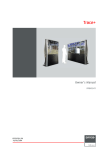
i70 Trace+
Installation Manual
R9040341
R5976660/02
18/11/2005
Barco nv Simulation Products
600 Bellbrook Ave, Xenia OH 45385
Phone: +1 (937) 372 7579
Fax: +1 (937) 372 8645
E-mail: [email protected]
Visit us at the web: www.eis.barco.com
Barco nv Simulation Products
Noordlaan 5, B-8520 Kuurne
Phone: +32 56.36.82.11
Fax: +32 56.36.84.86
E-mail: [email protected]
Visit us at the web: www.barco.com
Printed in Belgium
Copyright ©
All rights reserved. No part of this document may be copied, reproduced or translated. It shall not otherwise be recorded, transmitted or
stored in a retrieval system without the prior written consent of Barco.
Changes
Barco provides this manual ’as is’ without warranty of any kind, either expressed or implied, including but not limited to the implied warranties or merchantability and fitness for a particular purpose. Barco may make improvements and/or changes to the product(s) and/or the
program(s) described in this publication at any time without notice.
This publication could contain technical inaccuracies or typographical errors. Changes are periodically made to the information in this
publication; these changes are incorporated in new editions of this publication.
Trademarks
Brand and product names mentioned in this manual may be trademarks, registered trademarks or copyrights of their respective holders.
All brand and product names mentioned in this manual serve as comments or examples and are not to be understood as advertising for
the products or their manufactures.
Federal Communications Commission (FCC Statement)
This equipment has been tested and found to comply with the limits for a class A digital device, pursuant to Part 15 of the FCC rules.
These limits are designed to provide reasonable protection against harmful interference when the equipment is operated in a commercial
environment. This equipment generates, uses, and can radiate radio frequency energy and, if not installed and used in accordance with
the instruction manual, may cause harmful interference to radio communications. Operation of this equipment in a residential area may
cause harmful interference, in which case the user will be responsible for correcting any interference.
EN55022/CISPR22 Class A ITE (Information Technology Equipment)
Class A ITE is a category of all other ITE which satisfies the class A ITE limits but not the class B ITE limits. Such equipment should not
be restricted in its sale but the following warning shall be included in the instructions for use:
Warning : This is a class A product. In a domestic environment this product may cause radio interference in which case the user may be
required to take adequate measures.
Guarantee and Compensation
Barco provides a guarantee relating to perfect manufacturing as part of the legally stipulated terms of guarantee. On receipt, the purchaser
must immediately inspect all delivered goods for damage incurred during transport, as well as for material and manufacturing faults Barco
must be informed immediately in writing of any complaints.
The period of guarantee begins on the date of transfer of risks, in the case of special systems and software on the date of commissioning,
at latest 30 days after the transfer of risks. In the event of justified notice of complaint, Barco can repair the fault or provide a replacement
at its own discretion within an appropriate period. If this measure proves to be impossible or unsuccessful, the purchaser can demand a
reduction in the purchase price or cancellation of the contract. All other claims, in particular those relating to compensation for direct or
indirect damage, and also damage attributed to the operation of software as well as to other services provided by Barco, being a component
of the system or independent service, will be deemed invalid provided the damage is not proven to be attributed to the absence of properties
guaranteed in writing or due to the intent or gross negligence or part of Barco.
If the purchaser or a third party carries out modifications or repairs on goods delivered by Barco, or if the goods are handled incorrectly,
in particular if the systems are commissioned operated incorrectly or if, after the transfer of risks, the goods are subject to influences not
agreed upon in the contract, all guarantee claims of the purchaser will be rendered invalid. Not included in the guarantee coverage are
system failures which are attributed to programs or special electronic circuitry provided by the purchaser, e.g. interfaces. Normal wear as
well as normal maintenance are not subject to the guarantee provided by Barco either.
The environmental conditions as well as the servicing and maintenance regulations specified in the this manual must be complied with by
the customer.
Table of contents
TABLE OF CONTENTS
1. Safety . . . . . . . . . . . . . . . . . . . . . . . . . . . . . . . . . . . . . . . . . . . . . . . . . . . . . . . . . . . . . . . . . . . . . . . . . . . . . . . . . . . . . . . . . . . . . . . . . . . . . . . . . . . . . . . . . 3
1.1
1.2
Safety warnings. . . . . . . . . . . . . . . . . . . . . . . . . . . . . . . . . . . . . . . . . . . . . . . . . . . . . . . . . . . . . . . . . . . . . . . . . . . . . . . . . . . . . . . . . . . . . . . . . . . . . . . . . . . . . . . . . . . . . . . 3
Installation guidelines . . . . . . . . . . . . . . . . . . . . . . . . . . . . . . . . . . . . . . . . . . . . . . . . . . . . . . . . . . . . . . . . . . . . . . . . . . . . . . . . . . . . . . . . . . . . . . . . . . . . . . . . . . . . . . . . 3
2. Packaging and Dimensions . . . . . . . . . . . . . . . . . . . . . . . . . . . . . . . . . . . . . . . . . . . . . . . . . . . . . . . . . . . . . . . . . . . . . . . . . . . . . . . . . . . . . . 5
2.1
2.2
2.3
Packaging. . . . . . . . . . . . . . . . . . . . . . . . . . . . . . . . . . . . . . . . . . . . . . . . . . . . . . . . . . . . . . . . . . . . . . . . . . . . . . . . . . . . . . . . . . . . . . . . . . . . . . . . . . . . . . . . . . . . . . . . . . . . . 5
Box Content. . . . . . . . . . . . . . . . . . . . . . . . . . . . . . . . . . . . . . . . . . . . . . . . . . . . . . . . . . . . . . . . . . . . . . . . . . . . . . . . . . . . . . . . . . . . . . . . . . . . . . . . . . . . . . . . . . . . . . . . . . . 6
Dimensions . . . . . . . . . . . . . . . . . . . . . . . . . . . . . . . . . . . . . . . . . . . . . . . . . . . . . . . . . . . . . . . . . . . . . . . . . . . . . . . . . . . . . . . . . . . . . . . . . . . . . . . . . . . . . . . . . . . . . . . . . . . 6
3. Single-Channel Installation . . . . . . . . . . . . . . . . . . . . . . . . . . . . . . . . . . . . . . . . . . . . . . . . . . . . . . . . . . . . . . . . . . . . . . . . . . . . . . . . . . . . . . . 9
3.1
3.2
3.3
3.4
3.5
Opening the Shipping Crate. . . . . . . . . . . . . . . . . . . . . . . . . . . . . . . . . . . . . . . . . . . . . . . . . . . . . . . . . . . . . . . . . . . . . . . . . . . . . . . . . . . . . . . . . . . . . . . . . . . . . . . . . . 9
Unpacking the Carton Boxes. . . . . . . . . . . . . . . . . . . . . . . . . . . . . . . . . . . . . . . . . . . . . . . . . . . . . . . . . . . . . . . . . . . . . . . . . . . . . . . . . . . . . . . . . . . . . . . . . . . . . . . . 10
Unpacking the i70 Trace+ . . . . . . . . . . . . . . . . . . . . . . . . . . . . . . . . . . . . . . . . . . . . . . . . . . . . . . . . . . . . . . . . . . . . . . . . . . . . . . . . . . . . . . . . . . . . . . . . . . . . . . . . . . . 11
Lifting the Trace Projector Unit . . . . . . . . . . . . . . . . . . . . . . . . . . . . . . . . . . . . . . . . . . . . . . . . . . . . . . . . . . . . . . . . . . . . . . . . . . . . . . . . . . . . . . . . . . . . . . . . . . . . . . 15
Assembling the i70 Trace+ . . . . . . . . . . . . . . . . . . . . . . . . . . . . . . . . . . . . . . . . . . . . . . . . . . . . . . . . . . . . . . . . . . . . . . . . . . . . . . . . . . . . . . . . . . . . . . . . . . . . . . . . . . 17
3.5.1 Mounting the Trace Screen Unit onto the Trace Projector Unit . . . . . . . . . . . . . . . . . . . . . . . . . . . . . . . . . . . . . . . . . . . . . . . . . . . . . . . . . . . . . 17
3.5.2 Installing the Mirror. . . . . . . . . . . . . . . . . . . . . . . . . . . . . . . . . . . . . . . . . . . . . . . . . . . . . . . . . . . . . . . . . . . . . . . . . . . . . . . . . . . . . . . . . . . . . . . . . . . . . . . . . . . . 21
3.5.3 Installing the Lens. . . . . . . . . . . . . . . . . . . . . . . . . . . . . . . . . . . . . . . . . . . . . . . . . . . . . . . . . . . . . . . . . . . . . . . . . . . . . . . . . . . . . . . . . . . . . . . . . . . . . . . . . . . . . 23
3.5.4 Mounting The Safety Plate . . . . . . . . . . . . . . . . . . . . . . . . . . . . . . . . . . . . . . . . . . . . . . . . . . . . . . . . . . . . . . . . . . . . . . . . . . . . . . . . . . . . . . . . . . . . . . . . . . . 25
3.6 Stabilizing the i70 Trace+ . . . . . . . . . . . . . . . . . . . . . . . . . . . . . . . . . . . . . . . . . . . . . . . . . . . . . . . . . . . . . . . . . . . . . . . . . . . . . . . . . . . . . . . . . . . . . . . . . . . . . . . . . . . 25
3.7 Installing the Rear Cabinets . . . . . . . . . . . . . . . . . . . . . . . . . . . . . . . . . . . . . . . . . . . . . . . . . . . . . . . . . . . . . . . . . . . . . . . . . . . . . . . . . . . . . . . . . . . . . . . . . . . . . . . . . 27
3.8 Installing the Bezels . . . . . . . . . . . . . . . . . . . . . . . . . . . . . . . . . . . . . . . . . . . . . . . . . . . . . . . . . . . . . . . . . . . . . . . . . . . . . . . . . . . . . . . . . . . . . . . . . . . . . . . . . . . . . . . . . 28
4. Multi-Channel Installation. . . . . . . . . . . . . . . . . . . . . . . . . . . . . . . . . . . . . . . . . . . . . . . . . . . . . . . . . . . . . . . . . . . . . . . . . . . . . . . . . . . . . . . . 31
4.1
4.2
Possible Multi-Channel Configurations . . . . . . . . . . . . . . . . . . . . . . . . . . . . . . . . . . . . . . . . . . . . . . . . . . . . . . . . . . . . . . . . . . . . . . . . . . . . . . . . . . . . . . . . . . . . . 31
Multi-Channel Set Up. . . . . . . . . . . . . . . . . . . . . . . . . . . . . . . . . . . . . . . . . . . . . . . . . . . . . . . . . . . . . . . . . . . . . . . . . . . . . . . . . . . . . . . . . . . . . . . . . . . . . . . . . . . . . . . . 33
5. Single-Channel Connections. . . . . . . . . . . . . . . . . . . . . . . . . . . . . . . . . . . . . . . . . . . . . . . . . . . . . . . . . . . . . . . . . . . . . . . . . . . . . . . . . . . . 35
5.1
5.2
5.3
5.4
Connections Location . . . . . . . . . . . . . . . . . . . . . . . . . . . . . . . . . . . . . . . . . . . . . . . . . . . . . . . . . . . . . . . . . . . . . . . . . . . . . . . . . . . . . . . . . . . . . . . . . . . . . . . . . . . . . . . 35
Connections Overview . . . . . . . . . . . . . . . . . . . . . . . . . . . . . . . . . . . . . . . . . . . . . . . . . . . . . . . . . . . . . . . . . . . . . . . . . . . . . . . . . . . . . . . . . . . . . . . . . . . . . . . . . . . . . . 37
Power Cord Connection . . . . . . . . . . . . . . . . . . . . . . . . . . . . . . . . . . . . . . . . . . . . . . . . . . . . . . . . . . . . . . . . . . . . . . . . . . . . . . . . . . . . . . . . . . . . . . . . . . . . . . . . . . . . . 37
Operating the i70 Trace+ . . . . . . . . . . . . . . . . . . . . . . . . . . . . . . . . . . . . . . . . . . . . . . . . . . . . . . . . . . . . . . . . . . . . . . . . . . . . . . . . . . . . . . . . . . . . . . . . . . . . . . . . . . . . 38
5.4.1 Switching On . . . . . . . . . . . . . . . . . . . . . . . . . . . . . . . . . . . . . . . . . . . . . . . . . . . . . . . . . . . . . . . . . . . . . . . . . . . . . . . . . . . . . . . . . . . . . . . . . . . . . . . . . . . . . . . . . . 38
5.4.2 Switching to Standby . . . . . . . . . . . . . . . . . . . . . . . . . . . . . . . . . . . . . . . . . . . . . . . . . . . . . . . . . . . . . . . . . . . . . . . . . . . . . . . . . . . . . . . . . . . . . . . . . . . . . . . . . 39
5.4.3 Switching Off . . . . . . . . . . . . . . . . . . . . . . . . . . . . . . . . . . . . . . . . . . . . . . . . . . . . . . . . . . . . . . . . . . . . . . . . . . . . . . . . . . . . . . . . . . . . . . . . . . . . . . . . . . . . . . . . . . 39
5.5 Input Connections . . . . . . . . . . . . . . . . . . . . . . . . . . . . . . . . . . . . . . . . . . . . . . . . . . . . . . . . . . . . . . . . . . . . . . . . . . . . . . . . . . . . . . . . . . . . . . . . . . . . . . . . . . . . . . . . . . . 39
5.5.1 Source Connections . . . . . . . . . . . . . . . . . . . . . . . . . . . . . . . . . . . . . . . . . . . . . . . . . . . . . . . . . . . . . . . . . . . . . . . . . . . . . . . . . . . . . . . . . . . . . . . . . . . . . . . . . . 39
5.6 Communication Connections. . . . . . . . . . . . . . . . . . . . . . . . . . . . . . . . . . . . . . . . . . . . . . . . . . . . . . . . . . . . . . . . . . . . . . . . . . . . . . . . . . . . . . . . . . . . . . . . . . . . . . . . 42
5.6.1 RS232 Connection . . . . . . . . . . . . . . . . . . . . . . . . . . . . . . . . . . . . . . . . . . . . . . . . . . . . . . . . . . . . . . . . . . . . . . . . . . . . . . . . . . . . . . . . . . . . . . . . . . . . . . . . . . . . 42
5.7 Stereo Connection. . . . . . . . . . . . . . . . . . . . . . . . . . . . . . . . . . . . . . . . . . . . . . . . . . . . . . . . . . . . . . . . . . . . . . . . . . . . . . . . . . . . . . . . . . . . . . . . . . . . . . . . . . . . . . . . . . . 43
6. Multi-Channel Connections. . . . . . . . . . . . . . . . . . . . . . . . . . . . . . . . . . . . . . . . . . . . . . . . . . . . . . . . . . . . . . . . . . . . . . . . . . . . . . . . . . . . . . 45
6.1
6.2
6.3
6.4
Multi-Channel Power Cord Connections. . . . . . . . . . . . . . . . . . . . . . . . . . . . . . . . . . . . . . . . . . . . . . . . . . . . . . . . . . . . . . . . . . . . . . . . . . . . . . . . . . . . . . . . . . . . 45
Multi-Channel Input Connections . . . . . . . . . . . . . . . . . . . . . . . . . . . . . . . . . . . . . . . . . . . . . . . . . . . . . . . . . . . . . . . . . . . . . . . . . . . . . . . . . . . . . . . . . . . . . . . . . . . 46
Multi Channel Linked System Connections. . . . . . . . . . . . . . . . . . . . . . . . . . . . . . . . . . . . . . . . . . . . . . . . . . . . . . . . . . . . . . . . . . . . . . . . . . . . . . . . . . . . . . . . . 47
Multi-Channel Stereo Connections . . . . . . . . . . . . . . . . . . . . . . . . . . . . . . . . . . . . . . . . . . . . . . . . . . . . . . . . . . . . . . . . . . . . . . . . . . . . . . . . . . . . . . . . . . . . . . . . . 51
7. Multiple Multi-Channel Connections . . . . . . . . . . . . . . . . . . . . . . . . . . . . . . . . . . . . . . . . . . . . . . . . . . . . . . . . . . . . . . . . . . . . . . . . . . . 55
7.1
7.2
7.3
Multiple Multi-Channel Power Cord Connections . . . . . . . . . . . . . . . . . . . . . . . . . . . . . . . . . . . . . . . . . . . . . . . . . . . . . . . . . . . . . . . . . . . . . . . . . . . . . . . . . . 55
Multiple Multi-Channel Input Connections . . . . . . . . . . . . . . . . . . . . . . . . . . . . . . . . . . . . . . . . . . . . . . . . . . . . . . . . . . . . . . . . . . . . . . . . . . . . . . . . . . . . . . . . . . 56
Multiple Multi-Channel Stereo Connections . . . . . . . . . . . . . . . . . . . . . . . . . . . . . . . . . . . . . . . . . . . . . . . . . . . . . . . . . . . . . . . . . . . . . . . . . . . . . . . . . . . . . . . . 56
A. Adjustment Procedure. . . . . . . . . . . . . . . . . . . . . . . . . . . . . . . . . . . . . . . . . . . . . . . . . . . . . . . . . . . . . . . . . . . . . . . . . . . . . . . . . . . . . . . . . . . . . 59
A.1
A.2
A.3
Rotation adjustment . . . . . . . . . . . . . . . . . . . . . . . . . . . . . . . . . . . . . . . . . . . . . . . . . . . . . . . . . . . . . . . . . . . . . . . . . . . . . . . . . . . . . . . . . . . . . . . . . . . . . . . . . . . . . . . . . 59
Tilt Adjustment . . . . . . . . . . . . . . . . . . . . . . . . . . . . . . . . . . . . . . . . . . . . . . . . . . . . . . . . . . . . . . . . . . . . . . . . . . . . . . . . . . . . . . . . . . . . . . . . . . . . . . . . . . . . . . . . . . . . . . . 60
Adjusting the Mirror Position . . . . . . . . . . . . . . . . . . . . . . . . . . . . . . . . . . . . . . . . . . . . . . . . . . . . . . . . . . . . . . . . . . . . . . . . . . . . . . . . . . . . . . . . . . . . . . . . . . . . . . . . 61
Index. . . . . . . . . . . . . . . . . . . . . . . . . . . . . . . . . . . . . . . . . . . . . . . . . . . . . . . . . . . . . . . . . . . . . . . . . . . . . . . . . . . . . . . . . . . . . . . . . . . . . . . . . . . . . . . . . . . . . . 65
R5976660 I70 TRACE+ 18/11/2005
1
Table of contents
2
R5976660 I70 TRACE+ 18/11/2005
1. Safety
1. SAFETY
1.1
Safety warnings
WARNING: Before installing the system, first read the safety instructions in the safety manual (R5975125)
delivered with the projector.
Disconnect divice
The disconnect device here is the power supply plug. Always ensure easy access to this plug.
Mechanical stability
Always mount the safety plate! Using the i70 without the safety plate will not guarantee maximum stability and may lead to personal
injury!
Image 1-1
1.2
Safety Plate
Installation guidelines
Ambient temperature check
Max. ambient temperature: 35°C or 95°F
Min. ambient temperature: 0°C or 32°F
The projector will not operate if the ambient air temperature falls outside this range (0°C-35°C or 32°F-95°F).
R5976660 I70 TRACE+ 18/11/2005
3
1. Safety
Environment
Do not install the projector system in a site near heat sources such as radiators or air ducts, or in a place subject to direct sunlight,
excessive dust or humidity. Be aware that room heat rises to the ceiling; check that temperature near the installation site is not
excessive.
CAUTION:
Harmful environmental contamination precaution.
Environment condition check
The system must always be mounted in a manner which ensures the free flow of clean air into the system ventilation inlets as well
as free flow at the ventilation outlets. The installation must also allow easy access to consumable parts (dust filters, lamps, ...). For
installations in environments where the projector is subject to airborne contaminants such as that produced by smoke machines or
similar (these deposit a thin layer of greasy residue upon the projectors internal optics and imaging electronic surfaces, degrading
performance), then it is highly advisable and desirable to have this contamination removed prior to it reaching the projectors clean
air supply. Devices or structures to extract or shield contaminated air well away from the projector are a prerequisite, if this is not a
feasible solution then measures to relocate the projector to a clean air environment should be considered. Make sure the projector
never runs with dirty dust filters as this will dramatically reduce the lifetime of the consumables. It is advised to clean the dust
filters on a regular basis and to replace them at any lamp change. Barco reserves itself the right to refuse warranty replacement
of consumables if they have been used in a projector with dirty air filters. Only use the manufacturer’s recommended cleaning kit
which has been specifically designed for cleaning optical parts, never use industrial strength cleaners on the projector’s optics as
these will degrade optical coatings and damage sensitive optoelectronics components.
Failure to take suitable precautions to protect the projector from the effects of persistent and prolonged air contaminants will culminate in extensive and irreversible ingrained optical damage. At this stage cleaning of the internal optical units will be non-effective
and impracticable. Damage of this nature is under no circumstances covered under the manufacturer’s warranty and may deem
the warranty null and void. In such a case the client shall be held solely responsible for all costs incurred during any repair. It is the
clients responsibility to ensure at all times that the projector is protected from the harmful effects of hostile airborne particles in the
environment of the projector. The manufacturer reserves the right to refuse repair if a projector has been subject to wantful neglect,
abandon or improper use.
What about ambient light?
The ambient light level of any room is made up of direct and indirect sunlight and the light fixtures in the room. The amount of ambient
light will determine how bright the image will appear. So, avoid direct sunlight on the screen. Window that face the screen should
be covered by opaque drapery while the set is being viewed. It is desired to install the projection system in a room whose walls and
floor are of non-reflecting material. The use of recessed ceiling lights and a method of dimming those lights to an acceptable level
is also important. Too much ambient light will ’wash out’ the projected image. This appears as less contrast between the darkest
and lightest parts of the image. With bigger screens, the ’wash out’ becomes more important. As a general rule, darken the room to
the point where there is just sufficient light to read or write comfortably. Spot lighting is desirable for illuminating small areas so that
interference with the screen is minimal.
4
R5976660 I70 TRACE+ 18/11/2005
2. Packaging and Dimensions
2. PACKAGING AND DIMENSIONS
This chapter handles about the way the i70 Trace+ is packed and gives an overview of the dimensions.
•
Packaging
•
Box Content
•
Dimensions
2.1
Packaging
Way of Packaging
The i70 Trace+ is shipped in a wooden box. To provide protection during transportation, the products are surrounded with foam.
The package is secured with banding and fastening clips.
The Shipping Crate
The Shipping Crate consists of a Top Cover Crate and a Bottom Crate.
1
2
3
Image 2-1
Shipping Crate
1
2
3
Top Cover Crate
Small Cover
Carton Support
R5976660 I70 TRACE+ 18/11/2005
5
2. Packaging and Dimensions
2.2
Box Content
CAUTION: Do not unpack the i70 Trace+ to check this content list, First read this manual and follow the Installation Guidelines to Unpack and Install the i70 Trace+, otherwise damage may occur to the i70 Trace+ parts.
Content
•
•
2.3
1 Barco Trace:
-
1 Barco i70 Trace+ Projector Unit (Bottom Unit)
-
1 Barco i70 Trace+ Screen Unit (Top Unit)
Covers:
-
Left Top Bezel
-
Left Bottom Bezel
-
Right Top Bezel
-
Right Bottom Bezel
-
Rear Top Cabinet
-
Rear Bottom Cabinet (Already mounted on the i70 Trace+ Projector Unit)
-
Front Cover (Already mounted on the i70 Trace+ Projector Unit)
•
Bolts to mount the Covers to the i70 Trace+
•
1 Barco TLD 0.8:1 Lens (The lens is packed separately in a carton)
•
1 Remote Control Unit (RCU) + 2 Batteries 1,5V
•
1 Installation Manual
•
1 Owner’s Manual
Dimensions
Dimensions
The dimensions of the i70 Trace+ are given in mm and inch (25,4mm = 1 inch).
6
R5976660 I70 TRACE+ 18/11/2005
1042 mm
(41 inch)
25 mm
(1.0 inch)
2. Packaging and Dimensions
1390 mm
(54.7 inch)
mm
37
17
inc
h)
1992 mm
(78.4 inch)
8
(6
42 mm
(1.7 inch)
AIR OUTLET
Image 2-2
Front View Dimensions
R5976660 I70 TRACE+ 18/11/2005
7
2. Packaging and Dimensions
180 mm
(7.1 inch)
1641 mm
(65 inch)
Image 2-4
Top View Dimensions
762 mm
(30 inch)
395.5 mm
(15 6 inch)
Image 2-3
Right View Dimensions
67 mm
(3 inch)
Image 2-5
Bottom View Dimensions
8
R5976660 I70 TRACE+ 18/11/2005
3. Single-Channel Installation
3. SINGLE-CHANNEL INSTALLATION
Overview
•
Opening the Shipping Crate
•
Unpacking the Carton Boxes
•
Unpacking the i70 Trace+
•
Lifting the Trace Projector Unit
•
Assembling the i70 Trace+
•
Stabilizing the i70 Trace+
•
Installing the Rear Cabinets
•
Installing the Bezels
The i70 Trace+ is fully scalable from a Single-Channel to a Multi-Channel Configuration, this chapter will describe how to install a Single-Channel i70 Trace+ Configuration.
When setting up a Multi-Channel i70 Trace+ Configuration, follow these procedures until mounting the Bezels,
then continue with the Multi-Channel i70 Trace+ Installation (see "Multi-Channel Installation", page 31).
CAUTION: First read this manual and follow the Installation Guidelines to Unpack and Install the i70 Trace+,
otherwise damage may occur to the i70 Trace+ parts.
Always work with a team of 2 persons to perform these installation procedures.
3.1
Opening the Shipping Crate
Necessary tools
Cross headed screwdriver
How to open the Shipping Crate?
1. Release the fastening clips.
Image 3-1
Release the fastening clips
2. Remove the banding.
3. Loosen the screws on top of the Top Cover Crate.
R5976660 I70 TRACE+ 18/11/2005
9
3. Single-Channel Installation
Image 3-2
Loosen the screws on top of the Top Cover Crate
4. Remove the Top Cover Crate.
Image 3-3
Remove the Top Cover Crate
3.2
Unpacking the Carton Boxes
Necessary tools
No tools.
How to Unpack the Carton Boxes?
1. Take out the carton box that contains the RCU and the Manuals.
10
R5976660 I70 TRACE+ 18/11/2005
3. Single-Channel Installation
Image 3-4
Carton boxes inside the Crate
1
2
Barco TLD 0.8:1 Lens
Bolts + RCU + Manual
Following blots can be found inside the Carton Box:
a) 6 T-Bolts
b) 4 Bolts M8
c) 2 Bolts M5
Image 3-5
Bolts included in the Carton Box
2. The carton containing the lens is glued to the Bottom Crate, take out the Lens image 3-4.
3.3
Unpacking the i70 Trace+
CAUTION:
All covers are to be handled with care.
Necessary tools
Cross headed screwdriver
How to Unpack the rest of the covers?
1. Loosen the screws of the Small Cover.
R5976660 I70 TRACE+ 18/11/2005
11
3. Single-Channel Installation
Image 3-6
Loosen the screws of the Small Cover
2. Remove this Small Cover.
Image 3-7
Remove this Small Cover
3. Take out the 2 Metal Bars that are packed on top of this Cardboard Cover.
12
R5976660 I70 TRACE+ 18/11/2005
3. Single-Channel Installation
Image 3-8
Take out the 2 Metal Bars
4. Take out the Bezels and put them aside.
Image 3-9
Take out the Bezels and put them aside
5. Unpack the bezels, these will be mounted on the unit later on.
R5976660 I70 TRACE+ 18/11/2005
13
3. Single-Channel Installation
Image 3-10
Unpack the bezels, these will be mounted on the unit later on
6. Remove the Cardboard Cover that secures the Rear Top Cabinet’s position.
Image 3-11
Remove the Cardboard Cover
7. Take out the Rear Top Cabinet.
14
R5976660 I70 TRACE+ 18/11/2005
3. Single-Channel Installation
Image 3-12
Take out the Rear Top Cabinet
8. Remove the rest of the packing material.
The i70 Trace+ Projector Unit can now be lifted out of the Crate.
3.4
Lifting the Trace Projector Unit
Necessary tools
•
Nut Spinner M8
•
2 persons and the 2 Metal Bars to lift the i70 Trace+ Projector Unit
Removing the Rear Bottom Cabinet of the Trace Projector Unit.
1. Loosen the bolts connecting the Rear Bottom Cabinet to the i70 Trace+.
R5976660 I70 TRACE+ 18/11/2005
15
3. Single-Channel Installation
Image 3-13
Loosen the bolts connecting the Rear Bottom Cabinet.
2. Remove the Rear Bottom Cabinet.
How to Lift the Trace Projector Unit out of the Crate?
1. Slide in the 2 Metal Bars as illustrated and lift out the i70 Trace+ Projector Unit with the 2 persons.
Image 3-14
Slide in the 2 Metal Bars as illustrated and lift out the i70 Trace+ Projector Unit with the 2 persons
2. When the i70 Trace+ Projector Unit is lifted outside the Crate, remove the metal bars.
16
R5976660 I70 TRACE+ 18/11/2005
3. Single-Channel Installation
3.5
Assembling the i70 Trace+
Overview
•
Mounting the Trace Screen Unit onto the Trace Projector Unit
•
Installing the Mirror
•
Installing the Lens
•
Mounting The Safety Plate
What has to be done?
1.
The screen has to be mounted and fixed to the projector unit.
2.
The mirror has to be folded out.
3.
The mirror has to be mounted and fixed to the projector unit.
2
3
1
Image 3-15
The screen has to be mounted and fixed to the projector unit.
3.5.1
Mounting the Trace Screen Unit onto the Trace Projector Unit
Necessary tools
•
Protective Gloves
•
Nut spinner M8
•
6 T-Bolts
How to Mount the Trace Screen Unit onto the Trace Projector Unit?
1. Push on the top corners of the Front Panel until a click is heard.
R5976660 I70 TRACE+ 18/11/2005
17
3. Single-Channel Installation
Image 3-16
Push on the top corners of the Front Panel until a click is heard
Image 3-17
Push on the top corners of the front panel untill a click is heard
2. Loosen the Front Panel.
The Front Panel will come to front.
18
R5976660 I70 TRACE+ 18/11/2005
3. Single-Channel Installation
3. Pull off the Front Panel from its Magnet Lock and take it off completly
4. Take the Trace Screen Unit out off the Crate.
Caution: Don not touch the screen when handling the Trace Screen Unit, always wear protective gloves.
Always support the Trace Screen Unit, when putting it on the Trace Projector Unit, as indicated in the picture.
Image 3-18
Take the Trace Screen Unit out off the Crate
5. Put the Trace Screen Unit on the Trace Projector Unit.
R5976660 I70 TRACE+ 18/11/2005
19
3. Single-Channel Installation
Image 3-19
Mounting the Trace Screen Unit onto the Trace Projector Unit
6. Use the T-Bolts (3 on each side) to fix the assembly.
7. Reverse step 1 to reinstall the Front Cover back on the Trace Projection Unit.
20
R5976660 I70 TRACE+ 18/11/2005
3. Single-Channel Installation
In some cases, due to transportation, the indicated spring may move and cause the screen to move from its
place. Push the screen back to its place as indicated below.
Image 3-20
3.5.2
Installing the Mirror
Necessary tools
•
Nut Spinner M8
•
Nut Spinner M24
•
Flat Blade Screwdriver
How to install the Mirror?
1. Loosen the 4 bolts securing the Mirror Position during transportation and remove this Support.
R5976660 I70 TRACE+ 18/11/2005
21
3. Single-Channel Installation
Image 3-21
Loosen the 4 bolts securing the Mirror Position
2. Loosen the Mirror Bolts (one on each side) and remove the Mirror Bolt Holders.
Image 3-22
Loosen the Mirror Bolts and remove the Mirror Bolt Holders
3. Rotate the Mirror in the Operation Position.
22
R5976660 I70 TRACE+ 18/11/2005
3. Single-Channel Installation
1
2
Image 3-23
Mirror Installation
4. Insert the Mirror Bolt Holders.
5. Insert and tighten the bolts to secure the Mirror’s Operating Position.
3.5.3
Installing the Lens
How to install the Lens on the i70 Trace+?
Follow the next procedure:
1. Remove the foam rubber in the opening of the lens holder.
2. Take the lens assembly out of its packing material and remove the lens caps on both sides.
3. Move the handle (A) of the lens anchor system to the right.
R5976660 I70 TRACE+ 18/11/2005
23
3. Single-Channel Installation
Image 3-24
Lens installation
4. Push the lens, motors at the top, in the lens block gap horizontally, lining up the motor connector on the lens with the connector
on the lens block (B), until the lens clicks in the lens anchor system.
Image 3-25
Mounted Lens
5. Secure the lens by installing the 4 extra fixation lens bolts.
Image 3-26
Secure the lens by installing the 4 extra fixation lens bolts
24
R5976660 I70 TRACE+ 18/11/2005
3. Single-Channel Installation
3.5.4
Mounting The Safety Plate
How to mount the Safety Plate?
1. Mount the safety plate by bolting it with 4 bolts (removed from the mirror) onto the bottom plate.
Image 3-27
Mount the safety plate by bolting it with 4 bolts (removed from the mirror) onto the bottom plate
3.6
Stabilizing the i70 Trace+
Necessary tools
Screwdriver
How to Stabilize the i70 Trace+?
1. Move the i70 Trace+ to the desired position.
2. 4 Wheels are mounted to the Frame, these allow an easy positioning of the i70 Trace+.
Note: These wheels are accessible from:
From the front, when the front panel is removed.
From the rear, when the Rear Bottom Cabinet is removed.
R5976660 I70 TRACE+ 18/11/2005
25
3. Single-Channel Installation
Image 3-28
4 Wheels allow an easy positioning
Caution:
Allow an easy airflow, do not obstruct the Air Outlets when positioning the i70 Trace+.
Air Outlet
Air Outlet
Air Outlet
Image 3-29
Allow an easy airflow, do not obstruct the Air Outlets
3. Stabilize the i70 Trace+, insert a screwdriver in the hole and lower the 4 adjustable feet mounted to the Frame.
Image 3-30
Lower the 4 adjustable feet
Caution:
26
Do not forget to turn these feet back in the default upward position, when moving the i70 Trace+.
R5976660 I70 TRACE+ 18/11/2005
3. Single-Channel Installation
3.7
Installing the Rear Cabinets
Necessary tools
•
Nut spinner M8
•
4 Bolts M8
How to Install the Rear Cabinets?
1. Hook the Rear Top Cabinet onto the Stainless Steel Hook, mounted on the rear of the Trace Screen Unit.
Image 3-31
Rear Top Cabinet Installation
2. Tighten the 2 bolts to install the Rear Top Cabinet to the i70 Trace+, image 3-31.
3. Hook the Rear Bottom Cabinet into the Stainless Steel Hook on the rear bottom edge of the frame.
Caution: Be aware of scratching the Rear Top Cabinet while hinging on the Rear Bottom Cabinet.
Tip:
This is done by pulling away the side corners of the Rear Bottom Cabinet from the Rear Top Cabinet while hinging in.
R5976660 I70 TRACE+ 18/11/2005
27
3. Single-Channel Installation
Image 3-32
Rear Bottom Cabinet Installation
4. Tighten the 2 bolts to install the Rear Bottom Cabinet to the i70 Trace+, image 3-32.
3.8
Installing the Bezels
When installing a Multi-Channel i70 Trace+ Configuration , please wait to install the Bezels and first read the
Multi-Channel i70 Trace+ Installation (see "Multi-Channel Installation", page 31).
Necessary tools
•
Nut spinner M5
•
2 Bolts M5
How to install the Bezels?
1. Hook in the Bottom Bezels and push down.
28
R5976660 I70 TRACE+ 18/11/2005
3. Single-Channel Installation
Image 3-33
Hook in the Side Bottom Covers and push down
2. Hook the Top Bezels into the Bottom Bezels.
R5976660 I70 TRACE+ 18/11/2005
29
3. Single-Channel Installation
Image 3-34
Hook the Top Bezels into the Bottom Bezels
3. Insert and tighten the 2 blots (one on each side) on top of the i70 Trace+ to fix the Bezels.
30
R5976660 I70 TRACE+ 18/11/2005
4. Multi-Channel Installation
4. MULTI-CHANNEL INSTALLATION
When setting up a Multi-Channel i70 Trace+ Configuration, first start with the Single-Channel Installation Procedures until mounting the Bezels (see "Single-Channel Installation", page 9), then return to this Multi-Channel
i70 Trace+ Installation.
The i70 Trace+ is fully scalable from a Single-Channel to a Multi-Channel Configuration, this chapter will describe how to install a Multi-Channel i70 Trace+ Configuration.
Overview
4.1
•
Possible Multi-Channel Configurations
•
Multi-Channel Set Up
Possible Multi-Channel Configurations
The i70 Trace+ is fully scalable from a Single-Channel to a Multi-Channel Configuration, this chapter will describe some Configurations with 2 and 3 i70 Trace+ Units involved.
Possible Dual Channel Configurations
The following illustration shows some examples of a Dual Channel Configuration:
R5976660 I70 TRACE+ 18/11/2005
31
4. Multi-Channel Installation
165°
150°
90°
Image 4-1
Possible Dual Channel Configurations
Possible Triple Channel Configurations
The following illustration shows some examples of a Triple Channel Configuration:
32
R5976660 I70 TRACE+ 18/11/2005
4. Multi-Channel Installation
Image 4-2
Possible Triple Channel Configurations
4.2
Multi-Channel Set Up
How to Set Up a Multi-Channel Configuration?
1. When applicable use the locking pins on the side of the i70 Trace+ to join multiple units together.
R5976660 I70 TRACE+ 18/11/2005
33
4. Multi-Channel Installation
Image 4-3
Locking Pins
2. Mount the Bezels on the outside of the Multi-Channel Configuration (see "Installing the Bezels", page 28).
34
R5976660 I70 TRACE+ 18/11/2005
5. Single-Channel Connections
5. SINGLE-CHANNEL CONNECTIONS
The following procedures will describe the connections when installing a single i70 Trace+.
Overview
5.1
•
Connections Location
•
Connections Overview
•
Power Cord Connection
•
Operating the i70 Trace+
•
Input Connections
•
Communication Connections
•
Stereo Connection
Connections Location
Where to find the Connections?
The input panel and the power strip are located in the right bottom part of the unit, they are accessible from the front of the unit by
removing the front panel.
Input
Panel
Image 5-1
Patch-Panel Location
R5976660 I70 TRACE+ 18/11/2005
35
5. Single-Channel Connections
Description of the Connection Section
Source input
Power strip
Image 5-2
Connection Section Description
The Power Strip
The power strip is used to connect the projector, free plugs can be used to connect additional equipment.
WARNING: The maximum allowed “additional” power is 300W! When connecting extra apparatuses always
insure not to exceed the maximum allowed power (300W).
36
R5976660 I70 TRACE+ 18/11/2005
5. Single-Channel Connections
5.2
Connections Overview
Connections Overview
4
3
7
5
6
1
2
Image 5-3
Connections overview
1
5–BNC Cable Input
2
DVI Input
3
Phased L/R Signal Connections
4
IR Emitters Connections
5
Stereo In Input
6
RS232 Communication Connections
7
Com. 800 Peripherals Connection
For more information on the Multi-Channel Stereo Related Signals (Phased L/R Signal Connections and IR
Emitters Connections) see "Multi-Channel Stereo Connections", page 51.
5.3
Power Cord Connection
Power Cord Connection
The power input is auto-ranging from 90 to 240 VAC. Use the supplied Power Cord to connect the i70 Trace+ to the wall outlet. Plug
the female power connector into the male connector at the rear bottom of the i70 Trace+.
R5976660 I70 TRACE+ 18/11/2005
37
5. Single-Channel Connections
To wall outlet
Image 5-4
Power Cord Connection
5.4
Operating the i70 Trace+
Overview
5.4.1
•
Switching On
•
Switching to Standby
•
Switching Off
Switching On
How to Switch to Standby?
The i70 Trace+ will Start Up to Standby automatically when inserting the Power Cord.
38
R5976660 I70 TRACE+ 18/11/2005
5. Single-Channel Connections
How to Start Image Projection?
1. Press the Standby key on the RCU.
F3
F2
F4
F1
F5
EXIT
ADJ
ENTER
PAUSE
TEXT
PHASE
9
0
7
8
5
6
3
4
1
2
TREBLE
BASS
SHARPN
TINT
COLOR
BRIGHTN
CONTR
BALANCE
VOL
Image 5-5
Standby key on the RCU
Tip:
Point the RCU towards the i70 Trace+ Screen.
Note:
For more information on how to use the RCU see chapter ’Getting Started’ of the Owner’s Manual.
The IR Communication Led on the RCU will light up (for more information see chapter ’Getting Started’ of the Owner’s Manual).
The i70 Trace+ Status Led will Light Up Green and Image Projection will be started.
5.4.2
Switching to Standby
How to Switch to Standby?
1. Press the Standby key to switch the i70 Trace+ to standby.
5.4.3
Switching Off
How to Switch Off?
1. Unplug the Power Cord from the Wall Outlet.
5.5
Input Connections
Overview
•
5.5.1
Source Connections
Source Connections
Source Connection Specifications ?
•
The Input has a 5 BNC input terminals for 5 cable input and a DVI plug for DVI input.
•
Within the installation mode it is possible to setup the input for 5 cable or DVI (See Owner’s Manual).
•
Composite video and super video signals can be connected when an optional decoder is installed.
R5976660 I70 TRACE+ 18/11/2005
39
5. Single-Channel Connections
Image 5-6
RGB Input
Image Generator
Which signals can be connected to the Source Connection?
R
G
B
H
V
RGBHV
R
G
B
H
V
RGBS
R
G
B
S
-
RGsB
R
Gs
B
-
-
Connector name/
Input signal
DVI signals can be connected to the DVI input connector.
Pin assignment for the DVI connector
40
Pin 1
TMDS DATA2-
Pin 13
TMDS DATA3+
Pin 2
TMDS DATA2+
Pin 14
+5 Power
Pin 3
TMDS DATA2/4 Shield
Pin 15
Ground (for +5V)
Pin 4
TMDS DATA4-
Pin 16
Hot Plug Detect
Pin 5
TMDS DATA4+
Pin 17
TMDS DATA0-
Pin 6
DDC Clock
Pin 18
TMDS DATA0+
Pin 7
DDC Data
Pin 19
TMDS DATA0/5 Shield
Pin 8
No connect
Pin 20
TMDS DATA5-
Pin 9
TMDS DATA1-
Pin 21
TMDS DATA5+
Pin 10
TMDS DATA1+
Pin 22
TMDS Clock Shield
Pin 11
TMDS DATA1/3 Shield
Pin 23
TMDS Clock+
Pin 12
TMDS DATA3-
Pin 24
TMDS Clock-
R5976660 I70 TRACE+ 18/11/2005
5. Single-Channel Connections
How to select the Source Connection?
1. Key in 1 on the RCU.
How to change the Source Connection (Input 1) setting?
1. Press ADJUST or ENTER key to start up the Adjustment mode.
2. Push the cursor key ↑ or ↓ to select Installation.
ADJUSTMENT MODE
Select a path from below :
RANDOM ACCESS
INSTALLATION
SERVICE
Select with ↑ or ↓
then <ENTER>
<EXIT> to return
Menu 5-1
3. Press ENTER.
4. Press the cursor key ↑ or ↓ to select Input Slots.
INSTALLATION
INPUT SLOTS
NO SIGNAL
LENS
MENU POSITION [CENTER]
800-PERIPHERAL
CONFIGURATION
OSD COLOR
INTERNAL PATTERNS
Select with ↑ or ↓
then <ENTER>
<EXIT> to return
Menu 5-2
5. Press ENTER.
The internal system will scan the inputs and displays the result in the Input Slots menu.
INPUT SLOTS
SLOT SELECTION [AUTOMATIC]
X SLOT 1 : RGB - SOG
- SLOT 2 : DVI
Select with ↑ or ↓
<ENTER> to toggle
<EXIT> to return
Menu 5-3
6. Push the cursor key ↑ or ↓ to select the first or second slot.
R5976660 I70 TRACE+ 18/11/2005
41
5. Single-Channel Connections
Possible indications on input slot menu
•
•
Input 1:
-
RGS-SS [CV or HS&VS] = RGB analog signals, separate sync is composite sync or horizontal and vertical sync.
-
RGB-SOG = RGB analog signals, sync on green is composite sync
Input 2:
-
5.6
DVI
Communication Connections
5.6.1
RS232 Connection
What is possible with the RS232 Connection?
Computer
Image 5-7
RS232 Connection
•
•
Remote Control:
-
Easy adjustment of the i70 Trace+ when connected to an computer.
-
Allow storage of multiple i70 Trace+ configurations and set ups.
-
Wide range of control possibilities.
-
Address range from 0 to 255.
Data Communications: Sending data to the i70 Trace+ or copying the data from the i70 Trace+ to a memory device connected
to the computer.
Communication Port
This port allows communication with Barco Peripherals (Switchers, ...).
42
R5976660 I70 TRACE+ 18/11/2005
5. Single-Channel Connections
RCVDS 05 switcher
(R9827880)
Image 5-8
Communication Port
What is possible when connecting Barco’s RCVDS05?
•
Up to 20 inputs with Barco’s RCVDS 05 switcher (R9827880) and 90 inputs when RCVDS’s are linked via the expansion module.
•
Serial communication with the projector.
•
Remote control buttons on the RCVDS to control the projector (source selection and analog settings).
•
The selected source number will be displayed on a 2 digit display and the selected input module will be indicated with a LED
on the rear.
For more information about the use of the RCVDS05 switcher (R9827880), consult the owner’s manual of the RCVDS05.
Connecting an IR Remote Receiver to the projector
This infrared receiver unit makes it possible to control the projector from another room. There is a communication line cable between
the IR receiver and the projector or the RCVDS. The control information from the RCU can now be sent to the IR Remote Receiver.
The IR Remote Receiver displays the selected source on a 7-segment display.
5.7
Stereo Connection
How to Connect the Stereo Sync Signal?
The Stereo Sync Signal coming from the IG is connected to the Stereo In Mini DIN input on the Patch-Panel of the i70 Trace+.
R5976660 I70 TRACE+ 18/11/2005
43
5. Single-Channel Connections
I
m
a
g
e
G
e
n
e
r
a
t
o
r
Image 5-9
Stereo Sync Connection
44
R5976660 I70 TRACE+ 18/11/2005
6. Multi-Channel Connections
6. MULTI-CHANNEL CONNECTIONS
Overview
•
Multi-Channel Power Cord Connections
•
Multi-Channel Input Connections
•
Multi Channel Linked System Connections
•
Multi-Channel Stereo Connections
For more detailed information on the connections location see "Connections Location", page 35, the connections overview see "Connections Overview", page 37 or the communication connections see "Stereo Connection", page 43.
6.1
Multi-Channel Power Cord Connections
For more detailed information on Power Cords see "Power Cord Connection", page 37.
WARNING: Always use a Power Circuit that supports the necessary Current and Power Requirements for the
complete Multi-Channel Configuration.
Power Consumption Specifications
This product should be operated from an AC power source. Each i70 Trace+ needs 12A/100V, 5A/240V. Check if the mains voltage
and ampacity matches the projectors electrical ratings and ensure that the mains power system can support the i70 Trace+ power
requirements: 1200 Watts for each Barco Trace Unit.
How to connect the Power Cords in a Multi-Channel Configuration?
1. Use the supplied power cords to connect the i70 Trace+ Units to the wall outlet or connect them to a power strip.
R5976660 I70 TRACE+ 18/11/2005
45
6. Multi-Channel Connections
2
1
1
2
Image 6-1
Multi-Channel Power Cord Connections
Warning:
6.2
When using a power strip ensure the power strip cable supports the necessary current and power requirements for
the complete system.
Multi-Channel Input Connections
For more detailed info on the Input Connection see "Input Connections", page 39.
How to connect the Source Input in a Multi-Channel Configuration?
1. Connect the Source Signal coming from the Multi-Channel IG to the Multi-Channel i70 Trace+ Configuration.
46
R5976660 I70 TRACE+ 18/11/2005
6. Multi-Channel Connections
2
1
2
1
Channel 1
Channel 2
Image Generator
Image 6-2
Multi-Channel RGB Input Connections
6.3
Multi Channel Linked System Connections
CAUTION: Always use the Barco COM 800 Splitter, R9827941 (240V) or R9827948 (110V), when using the COM
800 protocol.
What can be done?
In a complex multi-channel setup, projectors can be controlled using the RS232 or COM800 Protocol.
CLO and Dynacolor™ can be controlled by both protocols, however by using the COM800 port for these 2 adjustments, the RS232
Port can still be used for general RS232 commands.
The following procedures will describe how to connect a RS232 Linked System and a COM800 Linked System.
How to connect a RS232 Setup?
1. Connect a Null Modem connector to the RS232 Input of the master–projector.
R5976660 I70 TRACE+ 18/11/2005
47
6. Multi-Channel Connections
Master
Null Modem Connector
Slave 1
Slave 2
Image 6-3
RS232 Setup
Daisy Chain to next Slave ...
2. Connect the output of the Null Modem connector to the RS232 Input of the first slave–projector (image 6-3).
3. Continue by connecting the RS232 Output of the first slave-projector to the RS232 Input of the second slave–projector (image 6-3).
4. Continue this daisy chain connection to connect all slave–projectors (image 6-3).
How to connect a COM800 Setup
Always use the Barco COM 800 Splitter (R9827941) when using the COM 800 protocol.
1. Use a data cable with at least 9 cores and 2 DB9 female connectors, just cross the pin 2 and pin 3 connection to make a Custom
Null Modem Cable.
48
R5976660 I70 TRACE+ 18/11/2005
6. Multi-Channel Connections
DB9
Female
Connector
Pin Number 1 2 3 4 5 6 7 8 9
Pin Number 1 2 3 4 5 6 7 8 9
DB9
Female
Connector
Image 6-4
Make a Custom Null Modem Cable
2. Use the Custom Null Modem Cable to connect the COM 800 port of the master-projector to the ’To Switcher’ port on the frontside
of the COM 800 Splitter.
R5976660 I70 TRACE+ 18/11/2005
49
6. Multi-Channel Connections
Custom Null Modem Cable
Front
TO SWITCHER
TO IR RECEIVER
COMM 800 Splitter
COM 800 Splitter 1 (R9827941)
Back
TO PROJ.1
TO PROJ.3
TO PROJ.4
To Slave 2
To Slave 3
Slave 1
Front
TO PROJ.2
TO SWITCHER
TO IR RECEIVER
COMM 800 Splitter
COM 800 Splitter 2
Back
Slave 4
TO PROJ.1
TO PROJ.2
TO PROJ.3
TO PROJ.4
To Slave 5
To Slave 6
To next COMM 800 Splitter
Image 6-5
Com 800 Connection
3. Continue by connecting the slave projectors to the ’To Proj.’ connectors on the backside of the COM 800 Splitter (image 6-5).
4. When dealing with more than 4 slave projectors, the ’To Proj.’ connectors on the backside of the COM 800 Splitter can also be
used to connect extra COM 800 Splitters (image 6-5).
50
R5976660 I70 TRACE+ 18/11/2005
6. Multi-Channel Connections
6.4
Multi-Channel Stereo Connections
How to Set Up the Stereo Parameters?
The Transport Delay Setting must be the same on all Projectors.
The L/R Phase must be same on all projectors, first adjust the L/R phase on the projector where the IR Emitter signal comes from,
then put the same value on the other projectors as well.
For more detailed information on how to adjust these parameters please consult the Owner’s Manual.
How to connect the Stereo Sync Signal in a Multi-Channel Configuration?
The Stereo Sync Signal coming from the IG is connected to the Stereo In Mini DIN input on the Patch-Panel of all the i70 Trace+
Units of the Multi-Channel Configuration.
On some IG’s, the Stereo Sync is already present in the Vertical Sync Signal.
2
1
Image Generator
1
2
Image 6-6
Multi-Channel Stereo Sync Connections
How to connect the Stereo Emitter Signal in a Multi-Channel Configuration?
The Stereo Emitter Signal is ’Looped Through’ all the i70 Trace+ Units of the Multi-Channel Configuration.
1. Connect the ’IR Emitters Out’ BNC Connector of the first i70 Trace+ to the ’IR Emitters In’ BNC Connector of the second i70
Trace+.
R5976660 I70 TRACE+ 18/11/2005
51
6. Multi-Channel Connections
2
1
1
2
Image 6-7
Connect the ’IR Emitters Out’ BNC Connector to the ’IR Emitters In’ BNC
2. Synchronize the Stereo Sync Signal to the Emitters by connecting a ’Phased L/R Signal Out’ BNC Connector to a free ’IR Emitters’
(In or Out) BNC connector.
52
R5976660 I70 TRACE+ 18/11/2005
6. Multi-Channel Connections
2
1
1
2
Image 6-8
Connect a free Phased L/R Signal Out BNC Connector to a free IR Emitter BNC connector
Caution:
Only make 1 link between a Phased L/R Signal Out’ BNC Connector and a free ’IR Emitters’ (In or Out) BNC connector.
All projectors will run on a common Stereo Sync (Phased L/R) signal.
The IR Emitters will all work in sync.
How to connect the Phased L/R Signal in a Multi-Channel Configuration?
The Phased L/R Signal is ’Looped Through’ all the i70 Trace+ Units of the Multi-Channel Configuration.
1. Connect a ’Phased L/R Signal’ BNC Connector of the first i70 Trace+ to a ’Phased L/R Signal’ BNC Connector of the second i70
Trace+.
R5976660 I70 TRACE+ 18/11/2005
53
6. Multi-Channel Connections
2
1
1
2
Image 6-9
Connect the Phased L/R Signal BNC Connectors
All projectors will run on a common Stereo Sync (Phased L/R) signal.
All Stereo IR Emitters will work in sync.
54
R5976660 I70 TRACE+ 18/11/2005
7. Multiple Multi-Channel Connections
7. MULTIPLE MULTI-CHANNEL CONNECTIONS
This chapter will describe the connections for e.g. a setup with 2 Triple-Channel Configurations. Each TripleChannel has its own IG.
Overview
•
7.1
Multiple Multi-Channel Power Cord Connections
•
Multiple Multi-Channel Input Connections
•
Multiple Multi-Channel Stereo Connections
Multiple Multi-Channel Power Cord Connections
For more detailed information on Power Cords ("Power Cord Connection", page 37).
WARNING: Always use a Power Circuit that supports the necessary Current and Power Requirements for the
complete Multi-Channel Configuration.
Power Consumption Specifications
This product should be operated from an AC power source. Each i70 Trace+ needs 12A/100V, 5A/240V. Check if the mains voltage
and ampacity matches the projectors electrical ratings and ensure that the mains power system can support the i70 Trace+ power
requirements: 1200 Watts for each Barco Trace Unit.
How to connect the Power Cords in a Multi-Channel Configuration?
All i70 Trace+ Units are connected to the wall outlet.
2
3
1
1
4
2
3
4
Image 7-1
Power Cord Connections in a Multiple Multi-Channel Configuration
WARNING: When using a power strip ensure the power strip cable supports the necessary current and power
requirements for the complete system.
R5976660 I70 TRACE+ 18/11/2005
55
7. Multiple Multi-Channel Connections
7.2
Multiple Multi-Channel Input Connections
For more detailed info on the Input Connection (see "Input Connections", page 39).
How to connect the Source Input in a Multiple Multi-Channel Configuration?
Each Triple-Channel has its own IG in this example, connect the Source Signal coming from each Multi-Channel IG to each MultiChannel i70 Trace+ Configuration.
2
3
1
4
2
1
Channel 2
Channel 1
Image Generator 1
3
4
Channel 2
Channel 1
Image Generator 2
Image 7-2
Source Input Connections in a Multiple Multi-Channel Configuration
7.3
Multiple Multi-Channel Stereo Connections
How to Set Up the Stereo Parameters?
The Transport Delay Setting must be the same on all Projectors.
The L/R Phase must be same on all projectors, first adjust the L/R phase on the projector where the IR Emitter signal comes from,
then put the same value on the other projectors as well.
For more detailed information on how to adjust these parameters please consult the Owner’s Manual.
How to connect the Stereo Sync Signal in a Multiple Multi-Channel Configuration?
The Stereo Sync Signal coming from both IG’s is connected to the Stereo In Mini DIN input on the Patch-Panel of both Triple-Channel
i70 Trace+ Configurations.
On some IG’s, the Stereo Sync is already present in the Vertical Sync Signal.
56
R5976660 I70 TRACE+ 18/11/2005
7. Multiple Multi-Channel Connections
1
3
2
1
2
4
5
4
3
Image Generator 1
6
5
6
Image Generator 2
Image 7-3
Stereo Sync Connections in a Multiple Multi-Channel Configuration
How to connect the Stereo Emitter and Phased L/R Signal in a Multiple Multi-Channel Configuration?
The Stereo Emitter Signal + Phased L/R Signal are ’Looped Through’ on all the i70 Trace+ Units of the Multiple Multi-Channel
Configurations.
It is possible to let Triple-Channel 1 work synchronous with IG 1. Triple-Channel 2, that is in asynchronous
mode, will then display the image at the frequency of IG 1.
Respect the following 2 rules when setting up such a configuration:
1. Connect one ’Phased L/R Out’ to a free ’IR Emitter’ (In or Out) on a projector running in Synchronous Mode.
2. All Trace Units connected to the synchronous IG must be set in Synchronous Mode.
3. All other Trace Units (Triple-Channel2, Triple-Channel3, ...) must be set in Forced Asynchronous Mode.
For more information on how to set a projector to ’Synchronous’ or ’Asynchronous’ Mode please consult the
Trace Owner’s Manual.
2
1
1
3
2
4
3
4
5
6
5
6
Triple Channel 1 = Trace 1+2+3
Triple Channel 2 = Trace 4+5+6
Synchronous Mode
Forced Asynchronous Mode
Image 7-4
Stereo Emitter and Phased L/R Signal Connections in a Multiple Multi-Channel Configuration
All projectors will run on a common Stereo Sync (Phased L/R) signal.
All Stereo IR Emitters in the room will work in sync.
R5976660 I70 TRACE+ 18/11/2005
57
7. Multiple Multi-Channel Connections
58
R5976660 I70 TRACE+ 18/11/2005
A. Adjustment Procedure
A. ADJUSTMENT PROCEDURE
A.1
Rotation adjustment
Necessary tools
Open ended spanner M13
How to adjust the rotation of the projected image?
We assume the i70 Trace+ is installed as a Single-Channel non-Stereo Configuration, an image is projected on the screen (Source
Signal or Internal Pattern).
1. Loosen the 2 bolts to remove the Rear Bottom Cabinet of the i70 Trace+.
2. Remove the Rear Bottom Cabinet.
Image A-1
3. The rotation adjustment bolts are located on the rear bottom of the i70Trace+.
Image A-2
4. Use the open ended spanner on the rotation adjustment bolts to rotate the projected image.
R5976660 I70 TRACE+ 18/11/2005
59
A. Adjustment Procedure
Image A-3
Image A-4
A.2
Tilt Adjustment
Necessary tools
Open ended spanner M17
How to adjust the rotation of the projected image?
1. Loosen the 2 bolts to remove the Rear Bottom Cabinet of the i70 Trace+.
2. Remove the Rear Bottom Cabinet.
Image A-5
3. The tilt adjustment bolts are located on the rear bottom of the i70 Trace+
60
R5976660 I70 TRACE+ 18/11/2005
A. Adjustment Procedure
Image A-6
4. Use the open ended spanner on the tilt adjustment bolts to tilt the projected image.
Image A-7
Image A-8
A.3
Adjusting the Mirror Position
Necessary tools
•
Nut spinner M8
•
Open ended spanner M24
•
Flat Blade Screwdriver
How to Adjust the Mirror Position?
We assume the i70 Trace+ is installed as a Single-Channel non-Stereo Configuration, an image is projected on the screen (Source
Signal or Internal Pattern).
1. Are the edges of the projected image parallel to the edges of the i70 Trace+ Screen?
If yes, The Mirror Position needs no Adjustment skip this procedure.
If no, Continue with the Mirror Adjustment.
R5976660 I70 TRACE+ 18/11/2005
61
A. Adjustment Procedure
Image A-9
The edges of the projected image are not parallel with the edges of the i70 Trace+ Screen
2. Loosen the 2 bolts to remove the Rear Top Cabinet of the i70 Trace+.
Image A-10
Loosen the 2 bolts to remove the Rear Top Cabinet
3. Use the nut spinner and the open ended spanner to loosen the Mirror Bolt.
Image A-11
Loosen the Mirror Bolt
4. The Mirror Bolt Holder is installed in the following default position.
62
R5976660 I70 TRACE+ 18/11/2005
A. Adjustment Procedure
Image A-12
Mirror Bolt Holder installed in the default position
5. Use the Flat Blade Screwdriver to remove the Mirror Bolt Holder from the Mirror Frame.
6. Put the Mirror Bolt Holder in the reverse position to the Mirror Frame.
Image A-13
Mirror Bolt Holder installed in the reverse position
7. Insert the Mirror Bolt into the holder and tighten until snug.
8. Adjust the Mirror Position until the edges of the projected image are parallel to the edges of the i70 Trace+ Screen.
Image A-14
Adjust the Mirror Position
9. Use the nut spinner and the open ended spanner to tighten the Mirror Bolt securing the Mirror’s Position.
R5976660 I70 TRACE+ 18/11/2005
63
A. Adjustment Procedure
64
R5976660 I70 TRACE+ 18/11/2005
Index
INDEX
A
Adjusting 61
Mirror Position 61
Adjustment 59–60
Procedure 59
Rotation adjustment
Tilt adjustment 60
Assembling 17
i70 Trace+ 17
IR Remote Receiver 43
Communication Port 43
L
59
B
Bezels 28
Install 28
Box 6
Content 6
M
C
Carton Boxes 10
Unpack 10
Communication 42
Connection 42
Configurations 31
Multi-Channel 31
Connection 37, 42–43
Communication 42
Power Cord 37
RS232 42
Stereo 43
Connections 35, 37, 39, 45–47, 51, 55–56
Input 39
Location 35
Multi Channel 47
Linked System 47
Multi-Channel 45–46, 51, 55
Input 46
Multiple 55
Power Cord 45
Stereo 51
Multiple Multi-Channel 55–56
Input 56
Power Cord 55
Stereo 56
Overview 37
Single-Channel 35
Source 39
Content 6
D
Dimensions
Lens 23
Install 23
Lift 15
Projector Unit 15
Linked System 47
Multi Channel 47
Connections 47
Location 35
Connections 35
5–6
I
Input 39, 46, 56
Connections 39
Multi-Channel 46
Connections 46
Multiple Multi-Channel 56
Connections 56
Install 21, 23, 28
Bezels 28
Lens 23
Mirror 21
installation 3
guidelines 3
Installation 9, 31
Multi-Channel 31
Single-Channel 9
Installing the Rear Cabinets 27
R5976660 I70 TRACE+ 18/11/2005
Mirror 21
Install 21
Mirror Position 61
Adjusting 61
Mounting 25
Safety Plate 25
Multi Channel 47
Linked System 47
Connections 47
Multi-Channel 31, 33, 45–46, 51, 55
Configuration 31
Connections 45
Input 46
Connections 46
Installation 31
Multiple 55
Connections 55
Power Cord 45
Connections 45
Set Up 33
Stereo 51
Connections 51
Multiple 55
Multi-Channel 55
Connections 55
Multiple Multi-Channel 55–56
Input 56
Connections 56
Power Cord 55
Connections 55
Stereo 56
Connections 56
O
Operate 38
Overview 37
Connections
37
P
Packaging 5
Power Cord 37, 45, 55
Connection 37
Multi-Channel 45
Connections 45
Multiple Multi-Channel
Connections 55
Projector Unit 15
Lift 15
55
R
RCVDS05
43
65
Index
Communication Port
RS232 42
Connection 42
S
safety 3
Safety Plate 25
Mounting 25
safety warnings 3
Shipping Crate 9
Open 9
Single-Channel 9, 35
Connections 35
Installation 9
Source 39
Connections 39
Stabilizing 25
Standby 39
Switch 39
Stereo 43, 51, 56
Connection 43
Multi-Channel 51
66
43
Connections 51
Multiple Multi-Channel
Connections 56
Switch 39
Standby 39
Switching 38–39
Off 39
On 38
56
T
Trace Projector Unit 17
Mount 17
Trace Screen Unit 17
Mount 17
U
Unpack 10
Carton Boxes
Unpacking 11
10
R5976660 I70 TRACE+ 18/11/2005
Revision Sheet
To:
Barco nv Simulation Products
Noordlaan 5, B-8520 Kuurne
Phone: +32 56.36.82.11, Fax: +32 56.36.84.86
E-mail: [email protected], Web: www.barco.com
From:
Date:
Please correct the following points in this documentation (R5976660/02):
page
R5976660
wrong
I70
TRACE+
18/11/2005
correct