1
. . . . . . . . . . . . . . . . . . . . . . . . . . . . . . . . . . . . .
.
Notice
The information in this guide is subject to change without notice.
COMPAQ COMPUTER CORPORATION SHALL NOT BE LIABLE FOR TECHNICAL OR
EDITORIAL ERRORS OR OMISSIONS CONTAINED HEREIN; NOR FOR INCIDENTAL
OR CONSEQUENTIAL DAMAGES RESULTING FROM THE FURNISHING,
PERFORMANCE, OR USE OF THIS MATERIAL.
This guide contains information protected by copyright. No part of this guide may be
photocopied or reproduced in any form without prior written consent from Compaq
Computer Corporation.
1997 Compaq Computer Corporation.
All rights reserved. Printed in the U.S.A.
Compaq, LTE, Contura, ProLinea, QuickLock, QuickBlank are
registered in the U. S. Patent and Trademark Office. Armada is a trademark of Compaq
Computer Corporation.
Contura is registered in the Philippines Patent Office.
Microsoft, MS-DOS, and Windows are registered trademarks of Microsoft Corporation.
Windows 95 is a trademark of Microsoft Corporation.
The software described in this guide is furnished under a license agreement or
nondisclosure agreement. The software may be used or copied only in accordance with the
terms of the agreement. Product names mentioned herein may be trademarks and/or
registered trademarks of their respective companies.
Maintenance and Service Guide
Compaq Armada 1500 Family of Personal Computers
First Edition (March 1997)
Spare Part Number 255011-001
Document Part Number 284820-001
Compaq Computer Corporation
. . . . . . . . . . . . . . . . . . . . . . . . . . . . . . . . . . . . .
Preface
Preface
This Maintenance and Service Guide is a troubleshooting guide that can be used for
reference when servicing the Compaq Armada 1500 Family of Personal Computers.
Additional information is available in the Service Quick Reference Guide and in
QuickFind.
Compaq Computer Corporation reserves the right to make changes to the Compaq
Armada 1500 Personal Computers without notice.
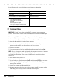
Symbols
The following symbols and words mark special messages throughout this guide:
!
WARNING: Text set off in this manner indicates that failure to follow directions in the
warning could result in bodily harm or loss of life.
CAUTION: Text set off in this manner indicates that failure to follow directions could
result in damage to equipment or loss of data.
IMPORTANT: Text set off in this manner presents clarifying information or specific
instructions.
NOTE: Text set off in this manner presents commentary, sidelights, or other points
of information.
Technician Notes
!
WARNING: Only authorized technicians trained by Compaq should attempt to repair
this equipment. All troubleshooting and repair procedures are detailed to allow only
subassembly/module level repair. Because of the complexity of the individual boards and
subassemblies, no one should attempt to make repairs at the component level or to
make modifications to any printed wiring board. Improper repairs can create a safety
hazard. Any indication of component replacement or printed wiring board modifications
may void any warranty or exchange allowances.
CAUTION: To properly ventilate the system being serviced, you must provide at least
3 inches (7.62 cm) of clearance on the front and back of the computer.
!
WARNING: The computer is designed to be electrically grounded. To ensure proper
operation, plug the AC power cord into a properly grounded electrical outlet only.
Preface
xi
. . . . . . . . . . . . . . . . . . . . . . . . . . . . . . . . . . . . .
.
Laser Safety
All Compaq systems, equipped with CD-ROM drives, comply with appropriate safety
standard including IEC 825. With specific regard to the laser, the equipment complies
with laser product performance standards set by government agencies as a Class 1 laser
product. It does not emit hazardous light; the beam is totally enclosed during all modes
of customer operation and maintenance.
CDRH Regulations
The Center for Devices and Radiological Health (CDRH) of the U.S. Food and Drug
Administration implemented regulations for laser products on August 2, 1976. These
regulations apply to laser products manufactured from August 1, 1976. Compliance is
mandatory for products marketed in the United States.
!
WARNING: Use of controls or adjustments or performance of procedures
other than those specified herein or in the CD ROM installation guide
may result in hazardous radiation exposure.
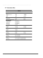
This system is classified as a CLASS 1 LASER PRODUCT. This label is located on
the outside of the system being serviced. A similar label also appears on the internal
CD-ROM installed in the system.
LASER INFO
Laser Type:
Wave Length:
Divergence Angle:
Output Power:
Polarization:
Numerical Aperture:
Semiconductor GaAIAs
780 +/- 35 nm
53.5 Degree +/- 1.5 Degree
Less than 0.2mW or 10,869 W•m-2sr-1
Circular
0.45 +/- 0.04
Only authorized technicians, service provider, dealer, or reseller should attempt to
repair this equipment. All troubleshooting and repair procedures are detailed to allow
only subassembly/module level repair. Because of the complexity of the individual
boards and subassemblies, no one should attempt to make repairs at the component
level or to make modifications to any printed wiring board. Improper repairs can create
a safety hazard as well as void the warranty.
xii
Preface
. . . . . . . . . . . . . . . . . . . . . . . . . . . . . . . . . . . . .
.
Battery Notice
This computer contains an internal lithium battery-powered real-time clock circuit.
There is a risk of explosion and injury if the battery is incorrectly replaced or handled
improperly. Do not attempt to recharge, disassemble, immerse in water, or dispose of it
in fire. Replacement should be done using the Compaq spare part for this computer.
The computer also contains a nickel metal hydride or lithium-ion battery pack. There is
a risk of fire and chemical burn if the battery pack is handled improperly. Do not
disassemble, crush, puncture, short external contacts, dispose in fire or water, or expose
it to temperatures higher than 60 degrees C.
In North America, dispose of nickel metal hydride or lithium-ion batteries by taking
advantage of the Compaq battery recycling program. You will be provided with a
postage-paid battery pack mailer preaddressed to a reclamation facility where the metals
are recycled.
In Europe, do not dispose of batteries and accumulators with general household waste.
Dispose of or recycle them by using the public collection system or returning them to
Compaq.
Serial Number
The serial number is located on the back of the computer directly below the parallel
connector.
Preface
xiii
. . . . . . . . . . . . . . . . . . . . . . . . . . . . . . . . . . . . .
.
Locating Additional Information
The following documentation is available to support the products:
xiv
■
Quick Setup
■
Reference Guide
■
Introducing Microsoft Windows 95
■
Compaq Service Quick Reference Guide
■
Service Training Guides
■
Compaq Service Advisories and Bulletins
■
Compaq QuickFind
■
Technical Reference Guide
Preface
. . . . . . . . . . . . . . . . . . . . . . . . . . . . . . . . . . . . .
Contents
Preface
Symbols
Technician Notes
Laser Safety
CDRH Regulations
Battery Notice
Serial Number
Locating Additional Information
xi
xi
xii
xii
xiii
xiii
xiv
Chapater 1
Computer Product Description
1.1 Computer Features and Models
1.2 Standard Features
1.2.1 Software Fulfillment
1.3 Options
1.3.1 Convenience Base
1.3.2 System Memory Options
1.3.3 External Battery Charger
1.3.4 External Keyboards and Pointing Devices
1.3.5 External Monitors
1.4 External Computer Components
1.4.1 Front and Left Side Components
1.4.2 Right Side Components
1.4.3 Rear Components
1.4.4 Bottom Components
1.4.5 Status Panel Lights
1-1
1-2
1-3
1-4
1-4
1-4
1-5
1-5
1-5
1-6
1-6
1-7
1-8
1-9
1-10
Chapter 2
Convenience Base Description
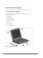
2.1 Models and Features
2.2 Convenience Base Features
2.3 Convenience Base Components
2.3.1 Front and Right Side Components
2.3.2 Rear Components
2-1
2-3
2-4
2-4
2-6
Contents
v
. . . . . . . . . . . . . . . . . . . . . . . . . . . . . . . . . . . . .
Chapter 3
Troubleshooting
3.1 Preliminary Steps
3.2 Clearing the Power-On and Setup Passwords
3.3 Power-On Self Test (POST)
3.4 POST Error Messages
3.5 Compaq Utilities
Running Computer Setup
Running Computer Checkup (TEST)
View System Information (INSPECT)
3.6 Diagnostic Error Codes
3.7 Troubleshooting Without Diagnostics
3.7.1 Solving Minor Problems
3-2
3-3
3-4
3-4
3-7
3-7
3-8
3-10
3-11
3-17
3-17
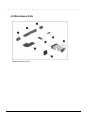
Chapter 4
Illustrated Parts for the Computer
4.1
4.2
4.3
4.4
4.5
4.6
4.8
4.9
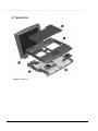
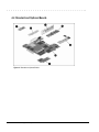
System Unit
Mass Storage Devices
Cables and Power Cords
Standard and Optional Boards
Options
Miscellaneous Parts
Shipping Boxes
Documentation
4-2
4-4
4-6
4-8
4-10
4-12
4-14
4-14
Chapter 5
Illustrated Parts for the Convenience Base
5.1 System Unit
5-2
Chapter 6
Removal and Replacement Preliminaries
6.1 Electrostatic Discharge
Generating Static
Preventing Electrostatic Damage to Equipment
Removing Batteries
Preventing Damage to Drives
vi
Contents
6-1
6-1
6-2
6-2
6-3
. . . . . . . . . . . . . . . . . . . . . . . . . . . . . . . . . . . . .
Grounding Methods
Grounding Workstations
Grounding Equipment
Recommended Materials and Equipment
6.2 Service Considerations
Tool Requirements
Cables and Connectors
6.3 Serial Number
6-3
6-4
6-4
6-5
6-6
6-6
6-6
6-6
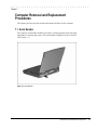
Chapter 7
Computer Removal and Replacement Procedures
7.1 Serial Number
7.2 Disassembly Sequence Chart
7.3 Design Overview
7.3.1 System Unit
7.3.2 Internal Boards
7.3.3 Video system
7.4 Preparing the Computer for Disassembly
7.4.1 Disconnecting the AC Power
7.4.2 Undocking the Computer
7.4.3 Battery Pack
7.4.4 DualBay Devices
7.4.5 PCMCIA
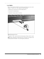
7.5 Modem
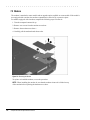
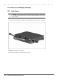
7.6 CD-ROM Drive
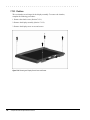
7.7 Keyboard
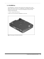
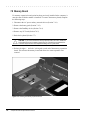
7.8 Memory Board
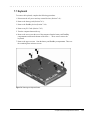
7.9 Hard Drive
7.10 Lithium Real Time Clock Battery
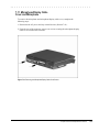
7.11 Microphone/Display Cable Cover and Microphone
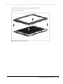
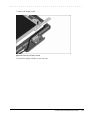
7.12 Clutch Covers/Display Assembly
7.12.1 Clutch Covers
7.12.2 Display Assembly
7.12.3 Clutches
7.12.4 Display latches
7-1
7-2
7-3
7-3
7-3
7-4
7-5
7-5
7-5
7-6
7-8
7-9
7-10
7-11
7-13
7-16
7-19
7-21
7-23
7-26
7-26
7-27
7-28
7-32
Contents
vii
. . . . . . . . . . . . . . . . . . . . . . . . . . . . . . . . . . . . .
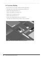
7.13 Top Cover Assembly
7.13.1 Power Button
7.13.2 Suspend Button
7.13.3 Left and Right Touchpad Buttons
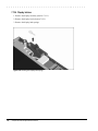
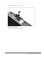
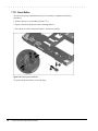
7.14 LED Status Panel
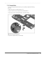
7.15 Audio Board, Speakers, and Audio Cable
7.16 DC-DC Converter
7.17 Fan
7.18 I/O Fixture Connector
7.19 System Board
7.20 AC Power
7.21 External Computer Components
7.21.1 Computer Logo
7.21.2 Computer Feet
7-34
7-36
7-37
7-38
7-40
7-41
7-43
7-47
7-49
7-51
7-53
7-54
7-54
7-54
Chapter 8
Upgrade Procedures for the Convenience Base
8.1 Serial Number
8.2 Preliminary Procedure
8.2.1 Installing the Optional 100BaseT Ethernet Network Module
8-1
8-1
8-2
Chapter 9
Specifications
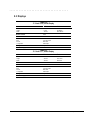
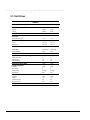
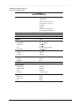
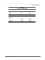
9.1 Computer
9.2 Displays
9.3 Hard Drives
9.4 Diskette Drive
9.5 CD-ROM Drive
9.6 Battery Packs
9.7 Convenience Base
9.8 External Power Supplies
9.9 System Interrupts
9.10 System DMA
9.11 System I/O Address
9.12 System Memory Map
viii
Contents
9-2
9-3
9-4
9-5
9-6
9-7
9-8
9-9
9-11
9-11
9-12
9-14
. . . . . . . . . . . . . . . . . . . . . . . . . . . . . . . . . . . . .
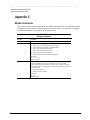
Appendix A
Comput
A-1
Appendix B
Power Cord Set Requirements
3-Conductor Power Cord Set
General Requirements
Country-Specific Requirements
Notes:
Appendix C
Modem Commands
Index
B-1
B-1
B-2
B-2
C-1
I-1
Contents
ix
. . . . . . . . . . . . . . . . . . . . . . . . . . . . . . . . . . . . .
Chapter 1
Computer Product Description
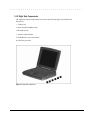
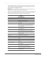
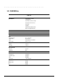
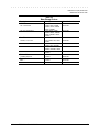
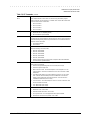
1.1 Computer Features and Models
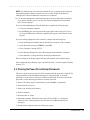
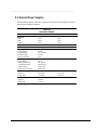
The Compaq Armada 1500 Family of Personal Computers is a line of multimedia
notebook computers with advanced modularity, processors, and video graphics. This
full-function, Pentium-based, family of notebook computers allows full desktop
functionality and connectivity through the use of an optional Convenience Base. The
following computer models are available:
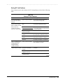
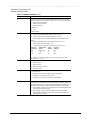
Table 1-1
Compaq Armada Personal Computers
Model
Pentium
Processor
Display
Level 2
Hard Drive Cache
1510
120-MHz
11.3-inch CSTN
1.0-GB
1510DM
120-MHz
11.3-inch CSTN
1.0-GB
1520
133-MHz
11.3-inch CSTN
1.0-GB
256-Kbyte
1520D
133-MHz
11.3-inch CSTN
1.0-GB
256-Kbyte
■
1520DM
133-MHz
11.3-inch CSTN
1.0-GB
256-Kbyte
■
■
1550T
133-MHz
12.1-inch CTFT
1.4-GB
256-Kbyte
1550DMT
133-MHz
12.1-inch CTFT
1.4-GB
256-Kbyte
■
■
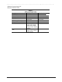
CD-ROM
Modem
Serial
Configuration
BM51
■
■
BM52
BM53
BM54
BM55
BM56
BM57
NOTE: All models have 16-MB of standard memory, upgradable to 80-MB.
Computer Product Description
1-1
. . . . . . . . . . . . . . . . . . . . . . . . . . . . . . . . . . . . .
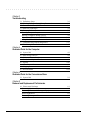
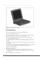
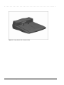
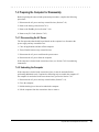
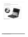
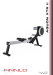
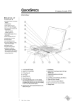
Figure 1-1. Compaq Armada Personal Computer
1.2 Standard Features
The Compaq Armada models have the following standard features:
1-2
■
120- or 133-MHz Pentium processors
■
16-MB of EDO dynamic random access memory (DRAM), expandable to 80 MB
■
1.4-GB or 1.0-GB, 2.5- inch with carrier, or 3-inch hard drive
■
11.3-inch Color Super Twist Nematic CSTN, or 12.1-inch Color Thin Film
Transistor (CTFT) SVGA displays
■
Supports Lithium Ion (Li-ion) and Nickel Metal Hydride (NiMH) modular battery
packs
■
SoundBlaster−compatible audio controller with internal stereo speakers and internal
microphone
■
Full-size 101 key compatible keyboard including 12 function keys, 8 cursor control
keys, inverted-T cursor control keys, and embedded numeric keypad
■
Four user-programmable keys
■
Touchpad pointing device
■
Operates from an internal battery pack, plus an optional battery pack in the
DualBay, or integrated AC power that is compatible with domestic or international
power sources
■
Power management and security features
Computer Product Description
. . . . . . . . . . . . . . . . . . . . . . . . . . . . . . . . . . . . .
■
Infrared interface for wireless communication with other IrDA-compliant devices at
data rates up to 4 mb/sec
■
Two standard device slots that will accommodate two types I and II and one type III
PC Cards, PCMCIA and CardBus cards; Compaq Telephony modem in the top slot
and Zoomed-Video in the bottom slot
■
176 pin expansion connector provides the interface to the convenience base options
■
Rear-panel ports provide connections for parallel and serial, external monitor,
keyboard/mouse, and IrDA compliant infrared devices
1.2.1
Software Fulfillment
Replacement software may be ordered directly from Compaq Computer Corporation.
Both the model and the serial numbers of the computer are needed to identify the
specific software available.
Computer Product Description
1-3
. . . . . . . . . . . . . . . . . . . . . . . . . . . . . . . . . . . . .
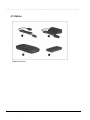
1.3 Options
The computer supports the following options:
■
Convenience Base pass through model
■
Convenience Base with Ethernet
■
Memory expansion boards
■
Li-ion and NiMH battery packs
■
Automobile Adapter
■
External Battery Charger
■
PCMCIA modem
■
AC power cords for international travelers
■
Hard drive upgrade
■
Internal modem
■
Internal CD-ROM drive
1.3.1 Convenience Base
Compaq Armada models support the following convenience base models:
■
Convenience base pass through
■
Convenience base with Ethernet (RJ-45 and BNC connectors); BNC connector not
available in North America
■
Convenience base with Ethernet (BNC connector); not available in North America
1.3.2 System Memory Options
The computer supports optional 8-, 16-, 32-, and 64-MB memory boards. The memory
boards are 60 ns EDO RAM without parity. System memory can be expanded to
80-MB of DRAM depending on the model.
1-4
Computer Product Description
. . . . . . . . . . . . . . . . . . . . . . . . . . . . . . . . . . . . .
1.3.3 External Battery Charger
The External Battery charger has the following features:
■
Two battery charge slots
■
Accepts both NiMH and Li-ion modular batteries
■
Charges one battery in 1.5 hours
■
Charges two batteries in 3 hours
1.3.4 External Keyboards and
Pointing Devices
Supports Compaq or Compaq compatible PS2 keyboards and pointing devices
1.3.5 External Monitors
The Compaq Armada models support all VGA Monitors up to 1024 x 768.
Computer Product Description
1-5
. . . . . . . . . . . . . . . . . . . . . . . . . . . . . . . . . . . . .
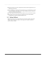
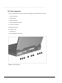
1.4 External Computer Components
The external computer components are illustrated and described in this section.
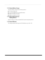
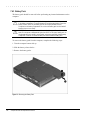
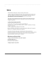
1.4.1 Front and Left Side Components
The front and left side external components are shown in the following figure and
identified in this section:
1
2
3
4
5
6
7
Display latches
Battery charge light
Power/Suspend light
DualBay compartment
PC Card slots
PC Card eject levers
RJ-11 port (on some models)
Figure 1-2. Front and Left Side Components
1-6
Computer Product Description
. . . . . . . . . . . . . . . . . . . . . . . . . . . . . . . . . . . . .
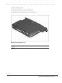
1.4.2 Right Side Components
The right side external components are shown in the following figure and identified in
this section:
1
2
3
4
5
6
Battery bay
Stereo/speaker headphone jack
Microphone jack
Volume control buttons
CD-ROM drive (on some models)
Cable lock provision
Figure 1-3. Right Side Components
Computer Product Description
1-7
. . . . . . . . . . . . . . . . . . . . . . . . . . . . . . . . . . . . .
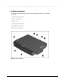
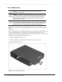
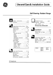
1.4.3 Rear Components
The rear components are shown in the following figure and identified in this section:
1
2
3
4
5
6
7
8
9
Serial connector
Serial number
Parallel connector
External monitor connector
AC Power connector
Docking connector
Airflow vents
Infrared port
Keyboard/Mouse connector
Figure 1-4. Rear Components
1-8
Computer Product Description
. . . . . . . . . . . . . . . . . . . . . . . . . . . . . . . . . . . . .
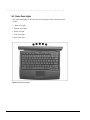
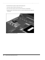
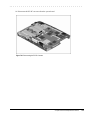
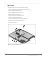
1.4.4 Bottom Components
The bottom external components are shown in the following figure and are identified in
this section:
1
2
3
4
5
6
Docking alignment guide
Modem compartment
Diskette drive
Diskette drive release latch
Docking latch receptacles
Battery bay traction grip
Figure 1-5. Bottom Components
Computer Product Description
1-9
. . . . . . . . . . . . . . . . . . . . . . . . . . . . . . . . . . . . .
1.4.5 Status Panel Lights
The status panel lights are shown in the following figure and are identified in this
section:
1
2
3
4
5
Hard drive light
Diskette drive light
Num Lock light
Caps Lock light
Scroll Lock light
Figure 1-6. Status Panel Lights
1-10
Computer Product Description
. . . . . . . . . . . . . . . . . . . . . . . . . . . . . . . . . . . . .
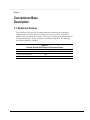
Chapter 2
Convenience Base
Description
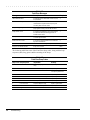
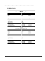
2.1 Models and Features
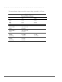
The convenience bases provide a permanent desktop solution for the computer by
eliminating the need to disconnect external devices such as a printer, keyboard, or
monitor when you undock the computer. All necessary connections and disconnections
are made automatically when the computer is docked and undocked. The following
convenience models are available:
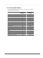
Table 2-1
Compaq Armada 1500 Family of Convenience Bases
Model
Serial Configuration
Convenience Base Pass Through model
BNH3
Convenience Base with Ethernet
BNH1
Convenience Base with Ethernet, BNC model
BNH3
Convenience Base Description
2-1
. . . . . . . . . . . . . . . . . . . . . . . . . . . . . . . . . . . . .
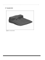
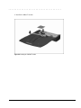
Figure 2-1. Compaq Armada 1500 Convenience Base
2-2
Convenience Base Description
. . . . . . . . . . . . . . . . . . . . . . . . . . . . . . . . . . . . .
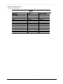
2.2 Convenience Base Features
The Convenience Base pass through model and the convenience base with Ethernet
model include the following features:
Convenience Base
pass through
Convenience Base
with Ethernet
Speaker/headphone
■
■
Audio Line-In
■
■
Serial
■
■
Parallel
■
■
External Monitor
■
■
Keyboard
■
■
Pointing Device
■
■
MIDI/Joystick
■
■
Cable lock provision
■
■
Pass through AC Power
■
■
Connections
Other Features
BNC connector (not available in all countries)
■
RJ-45 connector
■
Options
Monitor Stand
■
■
Localized Power Cords
■
■
Kensington lock
■
■
Optional 100BaseT Ethernet Upgrade
■
■
Convenience Base Description
2-3
. . . . . . . . . . . . . . . . . . . . . . . . . . . . . . . . . . . . .
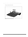
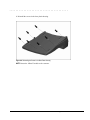
2.3 Convenience Base Components
The convenience base components are illustrated and described in this section.
2.3.1 Front and Right Side Components
The front and right side convenience base components are shown and identified in this
section.
1
2
3
4
5
6
7
8
9
:
;
Power button
Security cable lock provision
Docking lever
Battery charge light
Suspend button
Power/Suspend light
Retaining latch
Pass through AC power outlet
Docking connector
Docking alignment pins
Docking latches
2-4
Convenience Base Description
. . . . . . . . . . . . . . . . . . . . . . . . . . . . . . . . . . . . .
Figure 2-2. Convenience Base Front and Right Side Components
Convenience Base Description
2-5
. . . . . . . . . . . . . . . . . . . . . . . . . . . . . . . . . . . . .
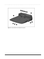
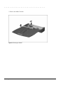
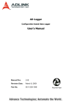
2.3.2 Rear Components
1
2
3
4
5
6
7
8
9
:
;
<
The rear components are shown in the following figure and identified in this section:
BNC connector (available on some models)
RJ-45 jack
Serial connector
Parallel connector
External monitor connector
MIDI/Joystick connector
Pointing device connector
Keyboard connector
Speaker/headphone jack
Audio Line-in jack
Fan
AC power connector
2-6
Convenience Base Description
. . . . . . . . . . . . . . . . . . . . . . . . . . . . . . . . . . . . .
Figure 2-3. Convenience Base Rear Components
Convenience Base Description
2-7
. . . . . . . . . . . . . . . . . . . . . . . . . . . . . . . . . . . . .
Chapter 3
Troubleshooting
This chapter contains troubleshooting information for the computer and the
convenience base. The basic steps in troubleshooting the computer include:
1. Completing the preliminary steps listed in Section 3.1.
2. Running the Power-On Self-Test (POST) as described in Section 3.3.
3. Running Computer Setup as described in Section 3.5
4. Running the Computer Checkup (TEST) as described in Section 3.5.
5. Performing the recommended actions described in the diagnostic tables in Section
3.6 if you are unable to exercise POST or Computer Checkup or if the problem
persists after running POST and Computer Checkup.
Follow these guidelines when troubleshooting:
■
Complete the recommended actions in the order in which they are given.
■
Repeat POST and Computer Checkup after each recommended action until the
problem is resolved and the error message does not return.
■
Once the problem is resolved, do not complete the remaining recommended actions.
■
Refer to Chapter 7 for any removal and replacement procedures that are
recommended for the computer. Refer to Chapter 8 for any removal or replacement
procedures that are recommended for the convenience base.
■
If the problem is intermittent, check the computer or convenience base several times
to verify that the problem is solved.
Troubleshooting
3-1
. . . . . . . . . . . . . . . . . . . . . . . . . . . . . . . . . . . . .
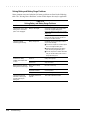
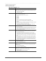
Use the following table for quick reference to troubleshooting information:
If You Want To:
Run:
Check for POST error messages
POST
Check that computer components are recognized and
running properly
Computer Checkup (TEST) under Compaq
Utilities
View information about the computer and installed or
connected devices
View System Information
(INSPECT)under Compaq Utilities
Perform any of the following:
n Check the system configuration
n Set the system power management
parameters
n Return the system to its original
configuration
n Check system configuration of installed devices
Computer Setup
3.1 Preliminary Steps
IMPORTANT: Use AC Power when running POST, Computer Setup, or Computer
Checkup. A low-battery condition could initiate Suspend or Hibernation and interrupt
the test.
Before running POST and Computer Checkup, complete the following steps:
1. Obtain established passwords. If you must clear the passwords, go to Section 3.2.
2. Ensure that the hard drive is installed in the computer.
3. Ensure that the battery pack is installed in the computer and the AC power is
connected to the computer and plugged into an AC power source.
4. Turn on the computer.
5. If a power-on password has been established, type the password and press Enter.
NOTE: The key icon appears on the display when the computer is turned on to indicate
that QuickLock/QuickBlank has been initiated. Type the power-on password to
exit QuickLock/QuickBlank. If the password is unknown, it must be cleared (see
Section 3.2).
6. Run Computer Setup (Section 3.5).
7. Use the Hotkeys to adjust the contrast (Fn+F9) and brightness (Fn+F10) to the center
of their ranges and leave the display open. On models with color TFT displays,
contrast is not applicable.
8. Turn off the computer and all external devices.
9. Disconnect any external devices that you do not want to test. If you want to use the
printer to log error messages, leave it connected to the computer.
3-2
Troubleshooting
. . . . . . . . . . . . . . . . . . . . . . . . . . . . . . . . . . . . .
NOTE: If a problem only occurs when an external device is connected to the computer,
the problem could be with the external device or its cable. Isolate the problem by
running POST with and without the external device connected.
10. Use Advanced Diagnostics and loopback plugs in the serial and parallel connectors
if you plan to test these ports. You may run Advanced Diagnostics from the hard
drive or from a diskette.
If you are running Diagnostics from the hard drive, complete the following steps:
a. Turn on or restart the computer.
b. Press F10 when the cursor appears in the upper right corner of the screen. If you
do not press F10 in time, restart the computer and try again. The Welcome screen
appears.
If you are running Diagnostics from a diskette, complete the following steps:
a. Insert the Diagnostics diskette into the diskette drive and turn on the computer.
b. At the Welcome Screen, press Enter to accept OK.
c. Select Computer Checkup (TEST).
d. Select Prompted Diagnostics after "Identifying System Hardware" completes.
e. Select Interactive Testing and follow the displayed instructions.
Refer to Chapter 4 for the description and spare part number of the loopback plugs.
After completing the preliminary steps, run POST (Section 3.3) and Computer Checkup
(Section 3.5).
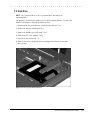
3.2 Clearing the Power-On and Setup Passwords
The power-on password prevents use of the computer until the password is entered. The
setup password prevents unauthorized changes to Computer Setup. To clear the
passwords, you must remove all power from the system board. If you do not know the
passwords, use the following procedure to clear the password:
1. Remove all battery packs from the battery bay and DualBay, if applicable.
2. Disconnect the AC power.
3. Remove the real time clock battery.
4. Wait five minutes.
5. Reconnect the AC power.
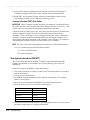
6. Restart the computer. During the Power-On Self Test (POST), a "162 System
Options not Set" message appears. (See Section 3.4 for additional POST error
messages).
7. Shut down the computer, then turn off the power again.
Troubleshooting
3-3
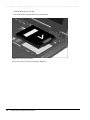
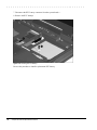
. . . . . . . . . . . . . . . . . . . . . . . . . . . . . . . . . . . . .
8. Replace the real time clock battery.
9. Install the battery pack(s).
10. Proceed with the troubleshooting procedures.
3.3 Power-On Self Test (POST)
The Power-On Self-Test (POST) is a series of tests that run every time the computer is turned on. POST
verifies that the system is configured and functioning properly
To run POST, complete the following steps:
1. Complete the preliminary steps. (Section 2.1).
2. Turn on the computer.
If POST does not detect any errors, the computer beeps once or twice to indicate that
POST has run successfully and boots from the hard drive or from a bootable diskette if
one is installed in the diskette drive.
3.4 POST Error Messages
This section contains typical error messages that may occur during the power-on selftest (POST).
If you receive an error message read the description and follow the recommended action
or run Computer Checkup from the Diagnostics diskette. Information about running
Computer Checkup is presented later in this chapter.
If POST detects an error, one of the following events occurs:
3-4
■
A message with the prefix "WARNING" appears informing you where the error
occurred. The system pauses until you press F1 to continue.
■
A message with the prefix "FATAL" appears informing you where the error
occurred. After the message, the system emits a series of audible beeps. The system
then stops.
■
The system emits a series of audible beeps. The system then stops.
Troubleshooting
. . . . . . . . . . . . . . . . . . . . . . . . . . . . . . . . . . . . .
Warning messages indicate a potential problem exists such as a system configuration
error. When F1 is pressed, the system should resume. You should be able to correct
problems that produce WARNING messages.
IMPORTANT: When a WARNING message includes the prompt to "RUN SCU," run
Computer Setup. (Computer Setup replaces the SCU utility.)
Fatal errors emit a beep and may display a FATAL message. Fatal errors indicate severe
problems, such as a hardware failure. Fatal errors do not allow the system to resume.
Some of the fatal error beep codes are listed at the end of this section.
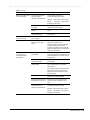
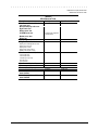
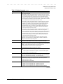
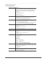
Table 3-1
Warning Messages
Message
Description
Clock not ticking correctly
The real-time clock is not ticking. Replace the real time clock
CMOS checksum invalid, run SCU
CMOS RAM information has been corrupted and needs to be
reinitialized by running Computer Setup.
CMOS failure, run SCU
CMOS RAM has lost power and needs to be reinitialized by running
Computer Setup.
Floppy controller failed
The diskette drive controller failed to respond to the reset command.
Power - down the system and check all appropriate connections. If
the diskette drive controller continues to fail, you may need to
replace the system board.
Floppy disk track 0 failed
The diskette drive cannot read track 0 of the diskette in the drive.
Try another diskette. If the problem persists, you may need to
replace the diskette drive.
Floppy information invalid, run SCU
The drive parameters stored in CMOS RAM do not match the
diskette drives detected in the system. Run Computer Setup.
Hard disk controller error
The hard drive controller failed to respond to the reset command.
Check the drive parameters. Power down the system and check all
appropriate connections.
Hardware info does not match video
card, run SCU
The video adapter type specified in CMOS RAM does not match the
installed hardware. Run Computer Setup.
Keyboard controller failure
The keyboard failed the self-test command. Replace the keyboard.
Keyboard failure
The keyboard failed to respond to the RESET ID command.
Press F1.
No interrupts from Timer 0
The periodic timer interrupt is not occurring. Press F1.
RAM parity error at location xxxx
A RAM parity error occurred at the specified (hex) location.
Press F1.
ROM at xxxx (LENGTH yyyy) with
nonzero checksum (zz)
An illegal adapter ROM was located at the specified address. An
external adapter (such as a video card) may be causing the conflict.
Run Computer Setup.
Time/Date corrupt - run SCU
The time and date stored in the real time clock have been corrupted,
possibly by a power loss. Run Computer Setup.
Unexpected amount of memory,
run SCU
The amount of memory detected by POST does not match the
amount specified in CMOS RAM. Run Computer Setup.
Hard disk xx failure (or error)
A failure or an error occurred when trying to access the hard drive.
Press F1 and continue.
Troubleshooting
3-5
. . . . . . . . . . . . . . . . . . . . . . . . . . . . . . . . . . . . .
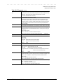
Table 3-2
Fatal Error Messages
Message
Description
Beep Code
CMOS RAM test failed
A walking bit test of CMOS RAM location 0E (Hex) - 3
3F (Hex) failed.
DMA controller faulty
A sequential read/write of the transfer count and
transfer address registers within the primary and
secondary DMA controllers failed.
4
Faulty DMA page registers
A walking bit read/write of the 16 DMA controller
page registers starting at location 80 Hex failed.
0
Faulty refresh circuits
A continuous read/write test of port 61h found that
bit 4 (Refresh Detect) failed to toggle within an
allotted amount of time.
1
Interrupt controller failed
A sequential read/write of various Interrupt
Controller registers failed.
5
ROM checksum incorrect
A checksum of the ROM BIOS does not match the
byte value at F000:FFFF.
2
RAM error at location xxxx
RAM error occurred during memory test.
None
Parity error at unknown location
Parity error occurred.
None
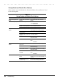
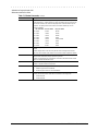
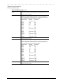
The following table lists some of the Fatal Error beep codes, along with the beep
sequence (short, long, pause) and the meaning of the beeps.
Table 3-3
Fatal Error Beep Codes
Beep Code Beep Sequence
Explanation
Remedy
0
S-S-S-P-S-S-L-P
The DMA page registers are
faulty.
Replace system board.
1
S-S-S-P-S-L-S-P
The refresh circuitry is faulty.
Replace system board.
2
S-S-S-P-S-L-L-P
The ROM checksum is incorrect.
1. Flash the ROM.
2. Replace system board.
3
S-S-S-P-L-S-S-P
The CMOS RAM test failed.
Replace system board.
4
S-S-S-P-L-S-L-P
The DMA controller is faulty.
Replace system board.
5
S-S-S-P-L-L-S-P
The interrupt controller failed.
Replace system board.
6
S-S-S-P-L-L-L-P
The keyboard controller failed.
Replace system board.
7
S-S-L-P-S-S-S-P
Graphics adapter is faulty.
Replace system board.
8
S-S-L-P-S-S-L-P
Internal RAM is faulty.
Replace processor board.
S = Short, L = Long, P = Pause
3-6
Troubleshooting
. . . . . . . . . . . . . . . . . . . . . . . . . . . . . . . . . . . . .
3.5 Compaq Utilities
Run the Compaq Utilities to view or test system information and installed or connected devices. Run
Compaq Utilities from either the computer hard drive or from diskette.
If running Compaq Utilities from a diskette, note the following:
n Use version 10.13c or later.
n You will not be able to make a utilities diskette.
n Use the Computer Setup diskette to run Computer Setup.
The Utilities menu includes the following:
n Computer Setup
n Computer Checkup (TEST)
n View System Information (INSPECT)
n Create Diagnostics diskette (hard drive only)
n Manage Diagnostics Partition (diskette only)
If the problem persists, call for support. Follow these steps to prepare for the support call:
1. Run Computer Checkup and save the device list to a file and print or save the log of errors.
2. Run the View System Information (INSPECT) utility and print or save that information.
3. Have the files or the printed information available when calling for support.
Running Computer Setup
Computer Setup contains a group of utilities that give you an overall picture of the
computer’s hardware configuration and aid in troubleshooting. Use these utilities to set
custom features, such as security options, power conservation levels, and startup
preferences.
A computer running Windows 95 automatically recognizes and configures the system
for new devices. However, if there is a configuration problem, or you want to view or
reset configuration settings, use Computer Setup.
Computer Setup provides two methods to view the computer’s configuration - by type
or connection. The default method for viewing Computer Setup is by type.
Troubleshooting
3-7
. . . . . . . . . . . . . . . . . . . . . . . . . . . . . . . . . . . . .
Categories by type include:
n System Features—security, power, boot management
n Communication—ports, modem, other communication devices
n Storage—storage-related devices such as hard drive or diskette
n Input Devices—keyboard, mouse, and other input devices
n Network—Network adapter, or other network-related devices (Available only when
docked or when PC Card is installed
n Audio—sound properties and audio device settings
n Video—monitor video device resources
n Other devices—devices that could not be categorized
Categories by connection include:
n System Features—security, power, boot management
n System Devices—keyboard, mouse, parallel and serial ports
n ISA—ISA bus and related devices
n PCI—PCI bus and connected devices
n PC Card (PCMCIA) —PC Card bus and PC Card devices
Running Computer Checkup (TEST)
Computer Checkup (TEST) determines whether the various computer components and
devices are recognized by the system and are functioning properly. You can display,
print, or save the information generated by Computer Checkup.
Computer Checkup is installed on the hard drive. If the hard drive is nonfunctional, you
can run it from a diskette.
NOTE: It is recommended that you make diskette copies of Computer Checkup and
keep them available for future needs. A current copy can be obtained from the Compaq
Customer Support Center.
3-8
Troubleshooting
. . . . . . . . . . . . . . . . . . . . . . . . . . . . . . . . . . . . .
Computer Checkup
To run Computer Checkup from the hard drive, complete the following steps:
1. Close all applications and shut down the computer.
2. Turn off the computer.
3. Turn on the computer.
4. When the cursor moves to the right side of the screen, press F10.
A Welcome Screen is displayed that is followed by the Compaq Utilities main menu.
5. From the Compaq Utilities main menu, select Computer Checkup (TEST).
A diagnostics menu is displayed.
6. Select the option to view the device list.
A list of the installed hardware devices is displayed.
NOTE: Computer Checkup does not detect all non-Compaq devices.
7. Verify that Computer Checkup correctly detected the installed devices.
If the list is correct, select OK. The Computer Checkup option menu is displayed
again.
If the list is incorrect, verify that the new devices are installed properly.
8. Select one of the following from the diagnostics menu:
■
Quick Check Diagnostics. Runs a quick, general test on each device with a
minimal number of prompts. If errors occur, they display when the testing is
complete. You cannot print or save the error messages.
■
Automatic Diagnostics. Runs an unattended, maximum testing of each device
with minimal prompts. You can choose how many times to run the tests, to stop
on errors, or to print or save a log of errors.
■
Prompted Diagnostics. Allows maximum control over testing the devices. You
can choose attended or unattended testing, decide to stop on errors, or choose to
print or save a log of errors.
9. Follow the instructions on the screen as the devices are tested. When testing is
complete, the Diagnostics menu appears.
10. Exit the Diagnostics menu.
NOTE: Exiting the Compaq Utilities menu restarts the computer and saves the
changes.
Troubleshooting
3-9
. . . . . . . . . . . . . . . . . . . . . . . . . . . . . . . . . . . . .
11. Look up the Computer Checkup error codes that were displayed by referring to
"Computer Checkup (TEST) Error Codes" and take the recommended action.
12. Rerun POST and Computer Checkup, taking the recommended actions in given
order until the problem is solved and no error messages occur.
Computer Checkup (TEST) Error Codes
IMPORTANT: Rerun Computer Checkup each time you complete a recommended action
step. If the problem is resolved when POST and Computer Checkup are rerun (i.e., with
no error codes) do not perform the remaining recommended action steps.
Computer Checkup (TEST) error codes occur if the system recognizes a problem while
running Computer Checkup. These error codes help identify possible defective
assemblies. Tables 3-4 through 3-14 list Computer Checkup error codes, a description
of the error condition, and the recommended action for resolving the condition. For
removal and replacement procedures for the computer, refer to Chapter 7. For removal
and replacement procedures for the convenience base, refer to Chapter 8.
NOTE: The error codes in the following tables are listed in an AYE-XX format, where:
A or AA = Number that represents the faulty assembly.
Y = Test or action that failed.
XX = Specific problem.
View System Information (INSPECT)
The View System Information (INSPECT) utility provides information about the
computer and installed or connected devices. You can display, print, or save the
information.
Follow these steps to run INSPECT from the hard drive:
1. Turn on the external devices that you want to test. Connect the printer if you want to
print the information.
2. Turn on or restart the computer.
3. Press F10 when the prompt appears in the right side of the display. The Compaq
Utilities screen appears.
4. Select View System Information (INSPECT) from the Diagnostics menu.
5. Select the item you want to view from the following list:
System
Memory
ROM
Audio
Keyboard
Operating system
System ports
System files
System storage
Windows files
Graphics
Miscellaneous
6. Follow the instructions on the screen to cycle through the screens, to return to the list
and choose another item, or to print the information.
3-10
Troubleshooting
. . . . . . . . . . . . . . . . . . . . . . . . . . . . . . . . . . . . .
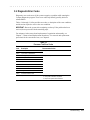
3.6 Diagnostic Error Codes
Diagnostic error codes occur if the system recognizes a problem while running the
Compaq Diagnostic program. These error codes help identify possibly defective
subassemblies.
Tables 3-4 through 3-14 list possible error codes, a description of the error condition,
and the action required to resolve the error condition.
IMPORTANT: Retest the system after completing each step. If the problem has been
resolved, do not proceed with the remaining steps.
For assistance in the removal and replacement of a particular subassembly, see
Chapter 7, "Removal and Replacement Procedures." For removal and replacement
procedures for the convenience base, see Chapter 8.
Table 3-4
Processor Test Error Codes
Error
Code
Description
101-xx
CPU test failed
103-xx
Coprocessor or Weitek Error
103-xx
DMA page registers test failed
104-xx
Interrupt controller master test failed
105-xx
Port 61 error
106-xx
Keyboard controller self-test failed
107-xx
CMOS RAM test failed
108-xx
CMOS interrupt test failed
109-xx
CMOS clock test failed
110-xx
Programmable timer load data test failed
113-xx
Protected mode test failed
114-01
Speaker test failed
Recommended Action
Replace the processor board and retest.
Replace the system board and retest.
1. Check system configuration.
2. Verify cable connections to speaker.
3. Replace the system board and retest.
Troubleshooting
3-11
. . . . . . . . . . . . . . . . . . . . . . . . . . . . . . . . . . . . .
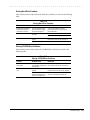
Table 3-5
Memory Test Error Codes
Error
Code
Description
200-xx
Memory machine ID test failed
203-xx
Memory system ROM checksum failed
203-xx
Write/Read test failed
The following steps apply to error codes 203-xx
through 215-xx:
204-xx
Address test failed
1. Remove the memory board and retest.
211-xx
Random pattern test failed
2 Install a new memory board and retest.
214-xx
Noise test failed
215-xx
Random address test failed
Recommended Action
The following steps apply to error codes 200-xx and
203-xx:
1. Flash the system ROM and retest.
2. Replace the system board and retest.
Table 3-6
Keyboard Test Error Codes
Error
Code
Description
300-xx
Failed ID Test
The following steps apply to error codes 300-xx
through 304-xx :
301-xx
Failed Selftest/Interface Test
1. Check the keyboard connection. If disconnected,
turn off the computer and connect the keyboard.
303-xx
Failed Individual Key Test
2. Replace the keyboard and retest.
304-xx
Failed Keyboard Repeat Test
3. Replace the system board and retest.
Recommended Action
Table 3-7
Parallel Printer Test Error Codes
Error
Code
Description
401-xx
Printer failed or not connected
The following steps apply to error codes 401-xx
through 403-xx :
402-xx
Failed Port Test
1. Connect the printer.
403-xx
Printer pattern test failed
Recommended Action
2. Check power to the printer.
3. Install the loop-back connector and retest.
4. Check port and IRQ configuration.
5. Replace the system board and retest.
3-12
Troubleshooting
. . . . . . . . . . . . . . . . . . . . . . . . . . . . . . . . . . . . .
Table 3-8
Diskette Drive Test
Error
Code
600-xx
Description
Recommended Action
601-xx
602-xx
Diskette ID drive types test
failed
Diskette format failed
Diskette read test failed
603-xx
604-xx
605-xx
606-xx
609-xx
610-xx
697-xx
698-xx
699-xx
Diskette write, read, compare test failed
Diskette random read test failed
Diskette ID media failed
Diskette speed test failed
Diskette reset controller test failed
Diskette change line test failed
Diskette type error
Diskette drive speed not within limits
Diskette drive/media ID error
The following steps apply to error codes 600-xx
through 698-xx:
1. Replace the diskette media and retest.
2. Check and/or replace the diskette power and signal
cables and retest.
3. Replace the diskette drive and retest.
4. Replace the system board and retest.
Run Computer Setup.
Table 3-9
Serial Test Error Codes
Error
Code
Description
1101-xx
Serial port test failed
Recommended Action
1. Check port configuration.
2. Replace the system board and retest.
Table 3-10
Hard Drive Test Error Codes
Error
Code
Description
1701-xx
Hard drive format test failed
1702-xx
1703-xx
Hard drive read test failed
Hard drive write/read/compare test
failed
Hard drive random seek test failed
Hard drive controller test failed
Hard drive ready test failed
Hard drive recalibration test failed
Hard drive format bad track test failed
Hard drive reset controller test failed
Hard drive park head test failed
Hard drive head select test failed
Hard drive conditional format test failed
Hard drive ECC* test failed
Hard drive power mode test failed
Network preparation test failed
Drive monitoring test failed
1704-xx
1705-xx
1706-xx
1707-xx
1708-xx
1709-xx
1710-xx
1715-xx
1716-xx
1717-xx
1719-xx
1724-xx
1736-xx
Recommended Action
The following steps apply to error codes 1701-xx
through 1736-xx :
1. Run Computer Setup.
2. Replace the hard drive and retest.
3. Replace the system board and retest.
* ECC = Error Correction Code
Troubleshooting
3-13
. . . . . . . . . . . . . . . . . . . . . . . . . . . . . . . . . . . . .
Table 3-11
Video Test Error Codes
Error
Code
Description
501-xx
Video controller test failed
The following apply to error codes 501-xx through
516-xx:
502-xx
Video memory test failed
1. Connect and external monitor and retest.
503-xx
Video attribute test failed
2. Replace the LED status board and retest.
504-xx
Video character set test failed
3. Replace the display and retest.
505-xx
Video 80 × 25 mode 9 × 14 character
cell test failed
Video 80 × 25 mode 8 × 8 character
cell test failed
Video 40 × 25 mode test failed
4. Replace the system board and retest.
506-xx
507-xx
508-xx
510-xx
Video 320 × 200 mode color set 0 test
failed
Video 320 × 200 mode color set 1 test
failed
Video 640 × 200 mode test failed
511-xx
Video screen memory page test failed
513-xx
Video gray scale test failed
514-xx
Video white screen test failed
516-xx
Video noise pattern test failed
2403-xx
Video memory test failed
The following steps apply to error codes 2403-xx
through 2456-xx:
2403-xx
Video attribute test failed
1. Run Computer Setup.
2404-xx
Video character set test failed
2. Disconnect external monitor and test with
internal LCD display.
2405-xx
Video 80 × 25 mode 9 × 14 character
cell test failed
Video 80 × 25 mode 8 × 8 character
cell test failed
3. Replace the display assembly and retest.
509-xx
2406-xx
2408-xx
2409-xx
3-14
Recommended Action
2410-xx
Video 320 × 200 mode color set 1 test
failed
Video 640 × 200 mode test failed
2411-xx
Video screen memory page test failed
2413-xx
Video gray scale test failed
2414-xx
Video white screen test failed
2416-xx
Video noise pattern test failed
2418-xx
ECG/VGC memory test failed
Troubleshooting
4. Replace the system board and retest.
. . . . . . . . . . . . . . . . . . . . . . . . . . . . . . . . . . . . .
Table 3-11 Continued
Error
Code
Description
Recommended Action
2419-xx
ECG/VGC ROM checksum test failed
The following steps apply to error codes 2403-xx
through 2456-xx:
2421-xx
ECG/VGC 640 × 200 graphics mode test
failed
1. Run Computer Setup.
2423-xx
ECG/VGC 640 × 350 16 color set test failed 2. Disconnect external monitor and test with internal
LCD display.
2423-xx
ECG/VGC 640 × 350 64 color set test failed 3. Replace the display assembly and retest.
2424-xx
ECG/VGC monochrome text mode test
failed
2425-xx
ECG/VGC monochrome graphics mode
test failed
2431-xx
640 × 480 graphics test failure
2433-xx
320 × 200 graphics (256 color mode) test
failure
4. Replace the system board and retest.
2448-xx
Advanced VGA Controller test failed
2451-xx
133-column Advanced VGA test failed
2456-xx
Advanced VGA 256 Color
test failed
2458-xx
Advanced VGA BitBLT test
The following applies to error codes 2458-xx through
2480-xx:
2468-xx
Advanced VGA DAC test
Replace the system board and retest.
2477-xx
Advanced VGA data path test
2478-xx
Advanced VGA BitBLT test
2480-xx
Advanced VGA Linedraw test
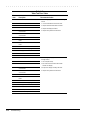
Table 3-12
Audio Test Error Codes
Error
Code
Description
Recommended Action
3206-xx
Audio System Internal Error
Replace the audio board and retest.
Troubleshooting
3-15
. . . . . . . . . . . . . . . . . . . . . . . . . . . . . . . . . . . . .
Table 3-13
Pointing Device Interface Test Error Codes
Error
Code
Description
Recommended Action
8601-xx
Mouse test failed
8603-xx
Interface test failed
The following steps apply to 8601-xx and 8603-xx:
1. Replace the top cover assembly.
2. Replace the system board and retest.
Table 3-14
CD-ROM Test Error Codes
3-16
Error
Code
Description
Recommended Action
3301-xx
CD-ROM drive read test failed
The following steps apply to error codes 3301-xx through
3305-xx and 6600-xx through 6623-xx:
3305-xx
CD-ROM drive seek test failed
1. Replace the CD and retest.
6600-xx
ID test failed
2. Replace the CD-ROM drive and retest.
6605-xx
Read test failed
3. Replace the system board and retest.
6608-xx
Controller test failed
6623-xx
Random read test failed
Troubleshooting
. . . . . . . . . . . . . . . . . . . . . . . . . . . . . . . . . . . . .
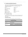
3.7 Troubleshooting Without Diagnostics
This section provides information about how to identify and correct some common
hardware, memory, and software problems. It also explains several types of common
messages that may be displayed on the screen. The following pages contain
troubleshooting information on:
■
Audio
■
Pointing device
■
Battery/Battery gauge
■
Memory
■
Diskette/Diskette drive
■
PC Card
■
Hard drive
■
Power
■
CD-ROM drive
■
Printer
■
Hardware installation
■
Screen (LCD and CRT)
■
Infrared connection
■
Software
■
Keyboard (Numeric keypad)
3.7.1 Solving Minor Problems
Some minor problems and possible solutions are outlined in the following tables. If the
problem appears related to a software application, check the documentation provided
with the software.
Solving Audio Problems
Some common audio problems and solutions are listed in the following table.
Table 3-15
Solving Audio Problems
Problem
Probable Cause
Solution(s)
Computer beeps once after
you turn it on.
This is typical; it indicates
successful completion of the
Power-On Self-Test (POST).
No action is required.
Computer does not beep after
the Power-On Self-Test
(POST).
Speaker volume is off or has
been turned down.
If the speaker icon is not displayed on the
display, press Fn+F5 to adjust the volume.
Beeps have been turned off.
Run Computer Setup and turn on beeps.
Troubleshooting
3-17
. . . . . . . . . . . . . . . . . . . . . . . . . . . . . . . . . . . . .
Solving Battery and Battery Gauge Problems
Some common causes and solutions for battery problems are listed in the following
table. The "Solving Power Problems" section in this chapter also may be applicable.
Table 3-16
Solving Battery and Battery Gauge Problems
Problem
Probable Cause
Solution(s)
Computer won’t turn on when
battery pack is inserted and
power cord is unplugged.
Battery is discharged.
Connect the computer to an external power
source and charge the battery pack.
Replace the battery pack with a fully charged
battery pack.
Check the battery connectors on the system
board to verify they are evenly spaced and
that they are not bent or broken.
Computer is beeping
and battery light is blinking.
Battery charge is low.
Immediately save any open file(s). Then do
any one of the following:
■ Connect the computer to an external power
source to charge the battery pack.
■ Initiate Suspend and replace the battery
pack with a fully charged battery pack.
■ Turn the computer off or initiate Hibernation
until you can find another power source or
charge the battery pack.
Computer battery light blinks
to indicate low- battery
condition, but computer does
not beep.
Low - battery beeps were
turned off.
Run Computer Setup to turn on the low battery warning beeps.
Volume is turned off or turned
down too low.
Press Fn+F5 to turn the speaker on and then
adjust the volume.
Battery light doesn’t light and Battery pack is already
battery pack won’t fast charge. charged.
Battery pack was exposed to
temperature extremes.
No action is necessary.
Allow time for the battery pack to return to
room temperature.
Battery pack is at end of its life. Replace battery pack.
Computer turned off and
information in memory was
lost when replacing the
battery pack.
The battery pack was not
replaced.
Turn off the computer and restart.
Continued
3-18
Troubleshooting
. . . . . . . . . . . . . . . . . . . . . . . . . . . . . . . . . . . . .
Table 3-16 Continued
Problem
Probable Cause
Solution(s)
Battery charge does not last
as long as expected.
Battery is being exposed to
high temperatures or
extremely cold temperatures.
Keep the battery pack within the
recommended temperature ranges.
Operating: 50°F to 104°F (10°C to 40°C)
Storage:
-4°F to 86°F (-20°C to 30°C )
Recharge the battery pack.
Battery has partially selfdischarged.
Recharge the battery. Discharge the battery
completely and then recharge it.
Power management is
disabled.
Set a power management level in Computer
Setup.
An external device or PC Card Turn off or disconnect external devices when
is draining the battery.
not using them.
Battery pack is warm to the
touch after charging.
Normal warming has occurred
due to charging.
No action is required.
Battery gauge is inaccurate.
The battery pack is new or has Fully charge the battery pack until the battery
not been used for a long
light on the computer turns off.
period.
Condition the battery pack by fully charging,
then fully discharging, and then fully
recharging. If condition persists, replace the
battery. If the battery gauge is still inaccurate,
replace the system board.
Battery pack operating time
is far less than the
documented average
operating time.
Power management is turned
off or disabled.
Enable power management in Computer
Setup and in Windows Power Properties. The
power management icon should be visible on
the status panel.
An external device or PC Card Turn off or disconnect external devices when
is draining the battery.
not using them.
Battery pack has partially
self-discharged.
To maintain the charge, leave battery packs
in the computer when it is connected to
external power.
If the computer is disconnected from external
power for more than two weeks, remove
battery packs from the computer to reduce
the discharge rate.
Fuel gauge is inaccurate.
Use the low battery warning beeps to
determine the low battery condition.
Battery pack is being drained
by high power-use accessory.
Reduce use of accessories which drain
power such as the CD-ROM drive or PC
Card.
Battery pack is being exposed
to high temperatures or
extremely cold temperatures.
Keep the battery pack within the
recommended temperature ranges:
Operating: 50°F to 104°F (10°C to 40°C)
Storage:
-4°F to 86°F (-20°C to 30°C ).
Recharge the battery pack.
Troubleshooting
3-19
. . . . . . . . . . . . . . . . . . . . . . . . . . . . . . . . . . . . .
Solving Diskette and Diskette Drive Problems
Some common causes and solutions for diskette and diskette drive problems are listed
in the following table.
Table 3-17
Solving Diskette and Diskette Drive Problems
Problem
Probable Cause
Solution(s)
Diskette drive light does not
turn on.
Diskette drive is not installed
properly.
Remove the diskette drive and install it
properly.
Diskette drive light stays on.
Diskette is damaged.
Run SCANDISK on the diskette. At the
system prompt, enter
SCANDISK A:
Diskette is incorrectly inserted. Remove diskette and reinsert.
Software program is damaged. Check the program diskettes.
Diskette drive cannot write to a Diskette is write-protected.
diskette.
Computer is writing to
the wrong drive.
Disable the diskette’s write-protect feature or
use a diskette that is not write-protected.
Check the drive letter in the path statement.
Not enough space is left on the Use another diskette.
diskette.
Drive error has occurred.
Run Computer Checkup from the Compaq
Diagnostics diskette.
Diskette is not formatted.
Format the diskette. At the system prompt,
enter
The wrong type of diskette is
being used.
Use the type of diskette required by the drive.
Diskette has a bad sector.
Copy files to hard drive or another diskette.
Reformat bad floppy.
Drive error has occurred.
Run Computer Checkup from the Compaq
Diagnostics diskette.
Diskette is not
formatted.
Format the diskette. At the system prompt,
enter
FORMAT A:
Diskette drive cannot read a
diskette.
FORMAT A:
Cannot boot from diskette.
3-20
Troubleshooting
Bootable diskette is not in
drive A.
Put the bootable diskette in drive A. If a
diskette drive is in the computer DualBay, that
is drive A.
Diskette Boot is disabled in
Computer Setup.
Run Computer Setup and enable Diskette
Boot from the Boot Management menu.
. . . . . . . . . . . . . . . . . . . . . . . . . . . . . . . . . . . . .
Solving Hard Drive Problems
Some common causes and solutions for hard drive problems are listed in the following
table.
Table 3-18
Solving Hard Drive Problems
Problem
Probable Cause
Solution(s)
Reading hard drive takes an
unusually long time after
restarting the computer.
System entered Hibernation
due to low-battery condition
and is now exiting from it.
Give the system time to restore the
previously saved data to its exact state
before Hibernation.
Hard drive error occurs.
Hard drive has bad sectors or
has failed.
Run Computer Checkup.
Hard drive is not seated
properly.
Turn off the computer, remove and reinsert
the hard drive, then turn the computer on.
Hard drive is damaged.
Replace the hard drive.
Hard drive does not work.
See POST error messages.
Solving CD-ROM Drive Problems
Some common causes and solutions for CD-ROM drive problems are listed in the
following table.
Table 3-19
Solving CD-ROM Drive Problems
Problem
Probable Cause
Solution(s)
CD-ROM drive cannot read a Compact disc is upside down Open the CD loading tray, lay the compact
compact disc.
or is improperly inserted in the disc in it (label side up), then close the tray.
CD-ROM drive.
CD-ROM drive does not
work.
CD-ROM drive is not seated
properly.
Shut down the computer, remove and
reinsert the drive, then turn on the computer.
CD-ROM drive was inserted
while the computer was on, in
Suspend, or in Hibernation.
Shut down computer; then turn it on again.
The drive is initialized during power up.
Troubleshooting
3-21
. . . . . . . . . . . . . . . . . . . . . . . . . . . . . . . . . . . . .
Solving Hardware Installation Problems
Some common causes and solutions for hardware installation problems are listed in the
following table.
Table 3-20
Solving Hardware Installation Problems
Problem
Probable Cause
Solutions(s)
A new device is not
recognized as part of
the computer system.
Cable(s) of new external
device are loose or
power cables are unplugged.
Ensure that all cables are properly and
securely connected.
Power switch of new external
device is not turned on.
Turn off the computer, turn on the external
device, then turn on the computer to integrate
the device with the computer system.
Device is not seated properly.
Turn off the computer and reinsert the device.
Solving Infrared Connection Problems
Some common causes and solutions for infrared connection problems are listed in the
following table.
Table 3-21
Solving Infrared Connection Problems
Problem
Cause
Cannot link with another
computer.
Interrupt request (IRQ) conflict. Check IRQ assignments for conflicts and
reassign as necessary.
Data transmission problem.
Solution(s)
Baud rate conflict.
Select the same baud rate for both
computers.
Direct sunlight, fluorescent
light, or flashing incandescent
light is close to the infrared
connections.
Remove the interfering light sources.
Interference from other wireless Keep remote control units such as wireless
devices.
headphones and other audio devices away
from the infrared connections
3-22
Troubleshooting
Physical obstruction.
Do not place objects between the two units
that will interfere with a line-of-sight data
transmission.
Movement.
Do not move either unit during data
transmission.
Orientation.
Adjust devices so that they point within
30 degrees of each other.
Distance.
Verify that devices are not more than
3 feet (1 m) apart.
. . . . . . . . . . . . . . . . . . . . . . . . . . . . . . . . . . . . .
Solving Keyboard/Numeric Keypad Problems
Some common causes and solutions for keyboard/numeric keypad problems are listed
in the following table.
Table 3-22
Solving Keyboard/Numeric Keypad Problems
Problem
Probable Cause
Solution(s)
Embedded numeric keypad on Num Lock function is not
computer keyboard is
enabled.
disabled.
Press the Fn+NumLk keys to enable the
Num Lock function and embedded numeric
keypad. The Num Lock icon on the status
panel turns on.
Keyboard is locked.
Enter the password to exit QuickLock.
QuickLock initiated.
Solving Pointing Device Problems
Some common causes and solutions for pointing device problems are listed in the
following table.
Table 3-23
Solving Pointing Device Problems
Problem
Cause
Solution(s)
External pointing device does
not work.
Incorrect device driver or no
device driver is installed.
Install the device driver.
The device driver is not
installed in Windows.
Install the device driver in Windows.
An external pointing device
is connected and the system
has disabled the internal
pointing device.
Initiate Suspend and disconnect the external
pointing device.
Integrated pointing device
does not work.
Troubleshooting
3-23
. . . . . . . . . . . . . . . . . . . . . . . . . . . . . . . . . . . . .
Solving Memory Problems
Some common causes and solutions for memory problems are listed in the following
table.
Table 3-24
Solving Memory Problems
Problem
Probable Cause
Solution(s)
Memory count during PowerOn Self-Test (POST) is
incorrect.
Optional memory expansion
board is installed incorrectly,
is incompatible with
the computer, or is defective.
Ensure that the optional memory expansion
board is installed correctly.
"Out of Memory" message is
displayed on the screen or
insufficient memory
error occurs during operation.
System ran out of memory for
the application.
Check the application documentation for
memory requirements.
Install additional memory.
Too many TSR (terminate and Remove from memory any TSR applications
stay resident) applications are that you do not need.
running.
3-24
Troubleshooting
. . . . . . . . . . . . . . . . . . . . . . . . . . . . . . . . . . . . .
Solving PC Card Problems
Some common causes and solutions for PC Card problems are listed in the following
table.
Table 3-25
Solving PC Card Problems
Problem
Probable Cause
Solution(s)
PC Card error messages
appear when the computer is
turned on.
The PC Card slot is disabled.
Run Computer Setup and enable the PC
Card slots on the Security Menu.
Computer does not beep
when PC Card is inserted
butt PC Card works correctly
System beeps are turned
down.
Press Fn+F5, then press the right arrow key
to increase the system beeps volume.
When turned on, the
computer does not beep
when a PC Card is inserted.
Card is not inserted properly
In Windows 95, double-click PC Card icon,
click the Global Settings tab. Deselect Disable
PC Card Sound Effects.
PC Card beeps are disabled.
Speaker is turned off or
volume is turned down.
Increase the volume.
PC Card drivers are not
installed.
Double-click the Add New Hardware icon in
the Control Panel for installation instructions.
The PC Card slots are
disabled.
Run Computer Setup and then select the
Security menu to enable PC Card slots.
Card or card driver is not
supported.
Check the list of PC Cards tested
successfully in Compaq PC Card platforms.
The PC Card drivers (Socket
Services, Card Services,
Card ID) fail with error
messages when the
computer is turned on.
The PC Card slot is disabled.
Run Computer Setup and select the Security
menu to enable PC Card slots.
PC Card modem, fax, or
network card does not work.
Card is not fully inserted into
the slot or is not inserted
properly.
Ensure the card is inserted in the correct
orientation.
Telephone cord is not
plugged in all the way.
Check and secure telephone connection.
Necessary drivers are not
installed (turned on).
Install drivers.
Continued
Troubleshooting
3-25
. . . . . . . . . . . . . . . . . . . . . . . . . . . . . . . . . . . . .
Table 3-25
Problem
Continued
PC Card modem or fax card
does not work.
Modem network PC Card
does not work.
Probable Cause
Solution(s)
You are trying to access the
card using the wrong COM
port.
See Chapter 9 to verify COM port.
The card conflicts with a serial
device.
See Chapter 9 to verify address.
The card is not supported.
Use supported cards only.
Network driver is not installed
or is not set up properly.
Install driver.
Telephone cord is not properly
connected.
Verify telephone connection.
Memory or storage card does SRAM and flash memory cards Install driver.
not work.
require the memory card driver
to be loaded (turned on).
Flash memory cards require
the Microsoft FlashFile System
to be loaded.
Hard drives on flash
mass storage cards require the
PC Card ATA driver to
be loaded.
3-26
Troubleshooting
You are trying to access the
hard drive card using the
wrong drive letter.
Double-click My Computer to verify the drive
letter assigned to the card.
The card is not
supported.
Check the list of PC Card cards tested
successfully in Compaq PC Card platforms.
. . . . . . . . . . . . . . . . . . . . . . . . . . . . . . . . . . . . .
Solving Power Problems
Also see "Solving Battery and Battery Gauge Problems" in this chapter.
Table 3-26
Solving Power Problems
Problem
Probable Cause
Solution(s)
Computer won’t turn on and
LEDs aren’t lit.
Computer is not connected
to a power source.
Insert battery or connect an external power
source.
Power cords to the external
power source are unplugged.
Ensure that power cords connecting the
computer and the external power source are
plugged in properly.
DC-DC Converter is defective.
Replace the DC-DC power board.
Integrated AC Power is defective. Replace the integrated AC Power and restart.
Computer turned off while it
was left unattended and the
power /suspend light is off.
Computer initiated Suspend
automatically or turned off
automatically when it was
docked in expansion base.
System initiated Hibernation
due to a critical low-battery
condition.
Replace the battery pack with a fully charged
battery pack or connect the computer to an
external power source. Then turn on the
computer.
System initiated Hibernation
after a preset timeout.
Turn on the computer.
The unit temperature
was exceeded.
Computer is in an exceedingly hot
environment. Let the computer cool down.
NOTE: To change the Hibernation setting in
Windows 95, click the Hibernation tab in
Power properties. Windows NT, run Computer
Setup and select Power Management.
Make sure the ventilation intake and exhaust
are not obstructed.
Troubleshooting
3-27
. . . . . . . . . . . . . . . . . . . . . . . . . . . . . . . . . . . . .
Solving Printer Problems
If you experience problems printing, run a printer self-test. Refer to the documentation
provided with the printer for instructions. If the self-test fails, it is a printer-specific
problem. Also refer to the printing section of the application documentation.
Table 3-27
Solving Printer Problems
Problem
Probable Cause
Solution(s)
Printer will not turn on.
The signal cable may not be
connected properly, or the
printer is unplugged.
Ensure that the signal cable is properly
connected and that the power cord is
connected to the electrical outlet.
Printer will not print.
Printer is not turned on or is off Turn the printer on and set it to on-line.
line.
Printer prints garbled
information.
The device drivers for the
application are not installed.
Refer to the printer documentation to install
the correct printer driver.
Printer that is set up for a
network is not connected
to the network.
Connect the printer to the network.
Printer cable is too long,
unshielded, or defective.
Replace the cable.
Paper tray is empty.
Fill the paper tray with paper and set the
printer to on-line.
Correct printer drivers are
not installed.
Refer to the printer documentation to install
the correct printer driver.
Cable is not connected
properly.
Ensure that the printer signal cable is
properly connected to the computer.
Cable is defective.
Replace the printer cable and retest.
Solving Screen Problems
This section lists some common causes and solutions for computer display and external
monitor problems.
You can perform a monitor self-test on an external VGA color or monochrome monitor
by disconnecting the monitor from the computer. To do so, complete the following
steps:
1.
2.
3.
4.
Turn off the monitor.
Turn off the computer.
Disconnect the monitor signal cable from the computer.
Turn on the monitor and allow it to warm up for one minute.
The screen should be white. A narrow black border may also appear on the left and
right sides of the display. Either of these displays indicates that the monitor is
working properly.
3-28
Troubleshooting
. . . . . . . . . . . . . . . . . . . . . . . . . . . . . . . . . . . . .
Table 3-28
Solving Screen Problems
Problem
Probable Cause
Solution(s)
Characters are dim.
The brightness or contrast
(if applicable) control is not
set properly.
Computer screen is in direct light.
Display is damaged.
You initiated QuickLock/
QuickBlank.
You may have another screen blanking utility installed.
Screen save was initiated after
the Power Management timeout
period of inactivity
If an STN screen is used, brightness/
contrast needs adjusting.
Screen has overheated
Adjust the control(s)using Fn+F9
(contrast) and Fn+F10 (brightness).
Screen is blank.
Suspend was initiated.
Computer screen is blank and
the screen on an external
monitor displays information.
Screen is blank and the
power/suspend light is blinking
Display was switched to the
external monitor.
Tilt the display or move computer.
Replace the display.
Enter the password to exit
QuickLock/QuickBlank.
Press any key and/or enter the
password.
Press any key or click the mouse.
Use the hotkeys to adjust the
brightness/contrast.
If the computer is in direct sunlight,
move it an allow it to cool.
Press the suspend button to exit
Suspend.
Press the Fn+F4 hotkey to display
information on the computer screen.
System is in Suspend
Press the Suspend button to exit
Suspend. Enter the power-on
password if prompted.
Screen is blank, the power/
System has entered a low-battery
Immediately connect the computer to
suspend light is blinking, and
condition
an external power source or replace
the battery light is blinking
the battery pack.
External monitor does not
External monitor was connected after Press the Fn+F4 hotkey to switch to
display information
the computer was turned on
the external monitor
The external monitor signal cable
Verify the cables are properly
or power cord is not properly
connected.
connected.
Distorted or garbled characters The ANSI.SYS driver is not in the
Add the ANSI.SYS driver to the
on the screen are mixed with text. CONFIG.SYS file or the path is
CONFIG.SYS file. Add the following
incorrect.
line: DEVICE=C:\ANSI.SYS
Garbled characters on internal
You are using 800 × 600 or higher
Restart the computer. If simultaneous
display or flashing internal display resolution on external display and
display is desired, use 640 × 480
when connected to external
have toggled back to internal display, resolution.
monitor.
which only supports
640 × 480 resolution.
The image on the external
You are using an external monitor
This is typical; no action is required.
monitor does not fill the screen. and simultaneously displaying an
image on the computer display.
Small red, green, or blue spots
Small spots, called on-pixels, often
This is typical; no action is required.
appear on the computer TFT
appear on TFT screens. Compaq
display.
limits the number of these on-pixels
to 0.003% of the approximately
1 million transistors that are on a
12.1-, or 11.3-inch display.
When in MS-DOS mode,
To maintain a high-quality image, the This is typical; no action is required.
the image on the computer
800 × 600 models do not
display does not fill the screen.
stretch the lower-resolution
When displaying simultaneously, image of MS-DOS mode to fill the
screen.
the image on the external
monitor may not be centered.
Troubleshooting
3-29
. . . . . . . . . . . . . . . . . . . . . . . . . . . . . . . . . . . . .
Solving Software Application Problems
Most software application or installation problems occur as a result of one or more of
the following:
■
The application was not installed correctly.
■
Memory was not allocated correctly.
■
A conflict exists between applications.
Table 3-29
Solving Software Application Problems
Problem
Probable Cause
Solution(s)
Cannot use an application.
The application has not been
added to the PATH statement.
Run the program with the full path name.
Insufficient memory to
run application.
System ran out of memory for
the application.
Check the application documentation for memory
requirements.
Install additional memory.
Too many TSR (terminate and Remove from memory any TSR applications that
stay resident) applications are you do not need.
running.
Application requires Windows
to be run in enhanced mode.
3-30
Troubleshooting
Exit Windows and enter again using the following
command to run in enhanced mode:
WIN/3
. . . . . . . . . . . . . . . . . . . . . . . . . . . . . . . . . . . . .
Solving Convenience Base Problems
Table 3-30
Display Problems and Solutions
Problem
Possible Cause
Solution(s)
Garbled characters
on internal display
or flashing internal
display when
connected to
external monitor.
Toggled to internal monitor
from an external monitor that
is using higher resolution than
that supported by the
computer.
Restart the system. If simultaneous display is desired, use
the resolution supported by the computer.
External monitor
display is distorted.
Energy Star Monitor is
selected on the Power
Management menu, and the
external monitor is not Energy
Star compliant.
Press any key or move the mouse to restore the display. If
the display remains distorted, turn the monitor off and then
back on. Deselect the Energy Star Monitor setting.
Computer screen
and external
monitor do not
display information
simultaneously.
Display was switched using the Press the Fn+F4 hotkeys to toggle through the three display
hotkeys.
possibilities.
External monitor was not
Initiate Suspend, turn on external monitor, then exit Suspend
turned on before the system was to integrate new monitor.
turned on.
External monitor was
connected after the
computer was turned on.
Initiate Suspend, connect external monitor, turn on the
monitor, then exit Suspend.
Table 3-31
Docking Problems and Solutions
Problem
Possible Cause
Solution(s)
The computer is not
properly docked in
the convenience
base.
The computer is not
properly centered over
docking latch.
Slide computer forward from convenience base. Center over
docking latch and replace. Push docking lever back to dock.
Pull docking lever forward to release computer and re-dock.
The computer is not coupled
to docking connector.
Table 3-32
Undocking Problems and Solutions
Problem
Possible Cause
The computer will not Connectors are tight.
undock.
Solution(s)
Grasp the computer with one hand and pull forward while
pulling forward on docking lever with other hand.
Security cable is locked.
Unlock security cable.
PC Card cable is attached to
the computer.
Remove cable from PC Cards before undocking.
The docking lever in the
convenience base may be
defective.
Replace the Convenience Base.
Troubleshooting
3-31
. . . . . . . . . . . . . . . . . . . . . . . . . . . . . . . . . . . . .
Table 3-33
External Device Installation Problems and Solutions
Problem
Possible Cause
Solution(s)
A new device is not Power switch of the new
Initiate Suspend, turn on external devices with power
recognized as part of external device was not turned switches, then exit Suspend to integrate the new device.
the computer system. on before the system was
turned on.
External device was connected Windows 95: Initiate Suspend, plug in and turn on external
after system was turned on.
devices with power switches, then exit Suspend to integrate
the new device.
Windows NT: Power off computer and external devices.
Power back on to integrate new device.
The signal cable or power
cord of the new device is
loose or disconnected.
Ensure that all cables are properly and securely connected.
The signal cable or power
cord of the new device may
be defective.
Try connecting a different signal cable and/or power cord.
Ensure that all power cords are properly and securely
plugged into an electrical outlet.
Table 3-34
Keyboard Problems and Solutions
Problem
Possible Cause
Solution(s)
External keyboard
does not work.
External keyboard may not
be securely connected or
may be connected to an
incorrect external connector.
Ensure that the external keyboard is properly and securely
connected to the external keyboard connector.
Table 3-35
Mouse Problems and Solutions
Problem
Possible Cause
External mouse does External mouse may not be
not work.
securely connected or may
be connected to an incorrect
external connector.
Mouse was connected after
system was turned on.
3-32
Troubleshooting
Solution(s)
Ensure that the external mouse is securely connected to the
mouse connector or the correct external connector.
Turn off the unit, connect the mouse, then turn the unit on to
integrate the mouse.
. . . . . . . . . . . . . . . . . . . . . . . . . . . . . . . . . . . . .
Solving Network Problems
This section provides guidelines for troubleshooting common Ethernet network
problems. Refer to these guidelines when you have determined that the computer in the
convenience base is not communicating with the network. These guidelines do not
discuss the process of debugging the network cabling.
These are common problems to check first. Refer to the tables on the following pages
for additional problems and solutions.
■
Ensure that the cabling is securely attached to the convenience base. A loose cable is
the most common cause of network problems. If the cable is loose, secure it and see
if the computer can communicate with the network.
■
Determine whether the current computer or another computer has communicated
with the network from the convenience base. If so, determine whether anything was
added or changed that could have stopped the network interface from working.
■
Run Diagnostics before installing the network drivers to verify that the network
interface is working correctly.
Table 3-36
Solving Ethernet Network Problems
Problem
Possible Cause
Solution(s)
When turned on, the The computer is not connected Connect the computer to the Ethernet network.
computer does not to the Ethernet network.
detect the network.
Suspend or Hibernation was
initiated.
Exit Suspend or Hibernation.
Windows 95: Restart the computer by clicking Start, Shut
Down, Restart the Computer.
Windows NT: Click Start, Shut Down. Power the computer
back on.
After installing
network operating
system, computer
does not detect
network interface.
The network driver fails to
Ensure that network drivers are loaded and that the drive path
load during system initialization. is correct.
If using a network interface
card connected to a parallel
port, the port has been
disabled.
Enable the parallel port. Restart the computer. Press F10
immediately when the cursor moves to the top right side of the
screen.
Suspend or Hibernation was
initiated.
Exit Suspend or Hibernation.
Windows 95: Restart the computer by clicking Start, Shut
Down, Restart the Computer.
Windows NT: Click Start, Shut Down. Power computer back
on.
Diagnostics reports The cable is not securely
a failure.
connected to the network
connector on the Ethernet
network.
Ensure that the cable is securely connected to the proper
network connector on the Ethernet network.
There is a problem with the
cable or a device at the other
end of the cable.
Ensure that the cable and device at the other end of the
network connection are operating properly.
Possible hardware failure.
Replace the Convenience Base.
Troubleshooting
3-33
. . . . . . . . . . . . . . . . . . . . . . . . . . . . . . . . . . . . .
Solving Ethernet Network Problems
Problem
Continued
Possible Cause
Diagnostics reports Network drivers are
no errors, but the
not loaded.
computer does not
communicate with
the network.
Solution(s)
Load the network drivers.
Windows 95: Restart the computer by clicking Start, Shut
Down, Restart the Computer.
Windows NT: Click Start, Shut Down. Power the computer
back on.
A network configuration error Contact the network administrator.
may have occurred (i.e., *.ini,
*.inf, *.nif, or CONFIG.SYS files
may need to be modified).
Suspend or Hibernation was
initiated.
Exit Suspend or Hibernation.
Windows 95: Restart the computer by clicking Start, Shut
Down, Restart the Computer.
Windows NT: Click Start, Shut Down. Power computer back
on.
The computer
The computer does not detect
stopped
network drivers.
communicating with
the network after
exiting Suspend.
Windows 95: Restart the computer by clicking Start, Shut
Down, Restart the Computer.
The computer
stopped
communicating with
the network for no
apparent reason.
The cable is not securely
connected to the network
connector on the Ethernet.
Ensure that the cable is securely connected to the
convenience base and Ethernet network.
General network failure.
Ensure that the network you are connected to is running and
has not experienced problems that would prevent the
connection.
Windows NT: Click Start, Shut Down. Power computer back
on.
The files for the network drivers Reinstall the network drivers.
have been corrupted.
IMPORTANT: If the 100BaseT Ethernet upgrade module has been installed, remove this
module before returning the convenience base for replacement.
3-34
Troubleshooting
. . . . . . . . . . . . . . . . . . . . . . . . . . . . . . . . . . . . .
Chapter 4
Illustrated Parts for the
Computer
This chapter provides illustrated parts and references for spare parts for the Compaq
Armada 1500 Family of Personal Computers. To review an illustrated parts breakdown
of the computer, refer to the Illustrated Parts Map that comes with this guide.
Illustrated Parts Catalog for the Computer
4-1
. . . . . . . . . . . . . . . . . . . . . . . . . . . . . . . . . . . . .
4.1 System Unit
Figure 4-1. System Unit
4-2
Illustrated Parts Catalog for the Computer
. . . . . . . . . . . . . . . . . . . . . . . . . . . . . . . . . . . . .
Table 4-1
System Unit
Item
Description
Spares Part Number
*
Keyboard (Belgian)
254968-181
*
Keyboard (Brazilian)
254968-035
*
Keyboard (Danish)
254968-081
*
Keyboard (French)
254968-051
*
Keyboard (French Canadian)
254968-121
*
Keyboard (German)
254968-041
*
Keyboard (Hangeul)
254968-033
*
Keyboard (Italian)
254968-061
*
Keyboard (Japanese)
254968-191
*
Keyboard (Latin American Spanish)
254968-161
*
Keyboard (Norwegian)
254968-091
*
Keyboard (Portuguese)
254968-131
*
Keyboard (Spanish)
254968-071
*
Keyboard (Swedish/Finnish)
254968-101
*
Keyboard (Swiss)
254968-111
*
Keyboard (Taiwanese)
254968-034
*
Keyboard (UK English)
254968-031
1
Keyboard (US/Canada)
254968-001
2
Top cover assembly
254978-001
3
Speakers
254979-001
4
Base enclosure assembly
212535-001
5
11.3-inch CSTN display assembly
254966-001
*
12.1-inch CTFT display assembly
* Not illustrated
254967-001
Illustrated Parts Catalog for the Computer
4-3
. . . . . . . . . . . . . . . . . . . . . . . . . . . . . . . . . . . . .
4.2 Mass Storage Devices
Figure 4-2. Mass Storage Devices
4-4
Illustrated Parts Catalog for the Computer
. . . . . . . . . . . . . . . . . . . . . . . . . . . . . . . . . . . . .
Table 4-2
Mass Storage Devices
Item
Description
Spares Part Number
1
10x CD-ROM Drive
254974-001
2
1.0-GB hard drive
254963-001
*
1.4-GB hard drive
254964-001
3
1.4-MB, diskette drive
254962-001
4
Lithium Ion Battery Pack
254960-001
Nickel Metal Hydride Battery Pack
254959-001
*
* Not illustrated
Illustrated Parts Catalog for the Computer
4-5
. . . . . . . . . . . . . . . . . . . . . . . . . . . . . . . . . . . . .
4.3 Cables and Power Cords
Figure 4-3. Cables and Power Cords
4-6
Illustrated Parts Catalog for the Computer
. . . . . . . . . . . . . . . . . . . . . . . . . . . . . . . . . . . . .
Table 4-3
Cables and Power Cords
Item
Description
Spares Part Number
1
CD-ROM drive cable
254975-001
2
Modem cable
165224-001
3*
AC Power cord (Australia/New Zealand)
246959-011
*
AC Power cord (Denmark)
246959-081
*
AC Power cord (Europe)
246959-021
*
AC Power cord (Italy)
246959-061
*
AC Power cord (Japan)
246959-291
*
AC Power cord (Korea)
246959-AD1
*
AC Power cord (Switzerland)
246959-AG1
*
AC Power cord (UK and Singapore)
246959-031
AC Power cord (US/Canada)
246959-001
4
RTC Battery
254971-001
5
Microphone (included in Miscellaneous
Parts kit)
254981-001
* Not illustrated
Illustrated Parts Catalog for the Computer
4-7
. . . . . . . . . . . . . . . . . . . . . . . . . . . . . . . . . . . . .
4.4 Standard and Optional Boards
Figure 4-4. Standard and Optional Boards
4-8
Illustrated Parts Catalog for the Computer
. . . . . . . . . . . . . . . . . . . . . . . . . . . . . . . . . . . . .
Table 4-4
Standard and Optional Boards
Item
1
Description
Spares Part Number
Memory board (SODIMM), 8-MB, 60 ns, nonparity
272108-001
*
Memory board (SODIMM), 16-MB, 60 ns, nonparity
272110-001
*
Memory board (SODIMM), 32-MB, 60 ns, non parity
220583-001
*
Memory board (SODIMM), 64-MB, 60 ns, non parity
273158-001
LED Status Board, 11.3-inch display
254958-001
LED Status Board, 12.1-inch display
255049-001
2
*
3
I/O Fixture Connector
254956-001
4
DC-DC Converter
254976-001
5
Audio Board
254957-001
6
System board, 120-MHz CPU
255010-001
*
System board, 133-MHz CPU with L2 cache
254949-001
*
System board, 150-MHz CPU with L2 cache, MMX
* Not yet available
Armada 1500 Series Telephony Modem
255014-001
7
* Not illustrated
Illustrated Parts Catalog for the Computer
4-9
. . . . . . . . . . . . . . . . . . . . . . . . . . . . . . . . . . . . .
4.5 Options
Figure 4-5. Options
4-10
Illustrated Parts Catalog for the Computer
. . . . . . . . . . . . . . . . . . . . . . . . . . . . . . . . . . . . .
Table 4-5
Options
Item
Description
Spares Part Number
1*
Power Cord (Australia/New Zealand)
246959-011
*
Power Cord (Denmark)
246959-081
*
Power Cord (Europe)
246959-021
*
Power Cord (Italy)
246959-061
*
Power Cord (Japan)
246959-291
*
Power Cord (Korea)
246959-AD1
*
Power Cord (Switzerland)
246959-AG1
*
Power Cord (UK and Singapore)
246959-031
Power Cord (US/Canada)
246959-001
2
Automobile adapter
254970-001
3
Li-ion modular battery pack
254960-001
*
NiMH modular battery pack
254959-001
External battery charger
254970-001
4
* Not illustrated
Illustrated Parts Catalog for the Computer
4-11
. . . . . . . . . . . . . . . . . . . . . . . . . . . . . . . . . . . . .
4.6 Miscellaneous Parts
Figure 4-6. Miscellaneous Parts
4-12
Illustrated Parts Catalog for the Computer
. . . . . . . . . . . . . . . . . . . . . . . . . . . . . . . . . . . . .
Table 4-6
Miscellaneous Parts
Item
Description
Spares Part Number
Plastics kit includes:
254981-001
1
Left clutch cover
2
Microphone/Display cable cover
3
Right clutch cover
4
RTC Battery cover
5
CD-ROM access door
6
Modem access door
7
Fan
254977-001
8
AC Power
254961-001
*
Miscellaneous Parts Kit (includes
microphone)
254981-001
*
Screw kit
258819-001
*
Tool kit (includes connector removal tool,
loop back plugs, and case utility tool)
100767-001
* Not illustrated
Illustrated Parts Catalog for the Computer
4-13
. . . . . . . . . . . . . . . . . . . . . . . . . . . . . . . . . . . . .
4.8 Shipping Boxes
Table 4-7
Shipping Boxes
Description
Spares Part Number
Shipping Carton (5 ea)
254972-001
Shipping Carton, display (1 ea)
254973-001
4.9 Documentation
Table 4-8
Documentation
4-14
Description
Spare Part Number
Compaq Armada Family Illustrated
Parts Map (10 ea)
255012-001
Compaq Armada Family Reference Guide
254984-001
Software CD Support
255097-001
Illustrated Parts Catalog for the Computer
. . . . . . . . . . . . . . . . . . . . . . . . . . . . . . . . . . . . .
Chapter 5
Illustrated Parts for the
Convenience Base
This chapter provides illustrated parts and spare parts references for the Compaq
Armada 1500 Family of Convenience Bases. To review an illustrated parts breakdown
of the convenience base, refer to the Illustrated Parts Map that comes with this guide.
Illustrated Parts for the Convenience Base
5-1
. . . . . . . . . . . . . . . . . . . . . . . . . . . . . . . . . . . . .
5.1 System Unit
Figure 5-1. Convenience Base
5-2
Illustrated Parts for the Convenience Base
. . . . . . . . . . . . . . . . . . . . . . . . . . . . . . . . . . . . .
Table 5-1
System Unit
Item
1
*
Description
Spares Part Number
Convenience Base (Pass through model) 254988-001
Convenience Base (Ethernet model)
254987-001
*
Convenience Base (Ethernet model, BNC) 254989-001
* Not illustrated
Table 5-2
Cables and Power Cords
Description
Spares Part Number
* AC Power cord (Australia/New Zealand)
246959-011
* AC Power cord (Denmark)
246959-081
* AC Power cord (Europe)
246959-021
* AC Power cord (Italy)
246959-061
* AC Power cord (Japan)
246959-291
* AC Power cord (Korea)
246959-AD1
* AC Power cord (Switzerland)
246959-AG1
* AC Power cord (UK and Singapore)
246959-031
* AC Power cord (US/Canada)
246959-001
* Not illustrated
Table 5-3
Options
Description
Spares Part Number
* Monitor Stand
254990-001
* 100BaseT Ethernet Upgrade
225436-001
* Not illustrated
Table 5-4
Shipping Boxes
Description
Spares Part Number
Shipping Carton (5 ea)
254991-001
Illustrated Parts for the Convenience Base
5-3
. . . . . . . . . . . . . . . . . . . . . . . . . . . . . . . . . . . . .
Chapter 6
Removal and Replacement
Preliminaries
This chapter provides general service information for the Compaq Armada 1500 Family
of Personal Computers. Adherence to the procedures and precautions described in this
chapter is essential for proper service.
6.1 Electrostatic Discharge
A sudden discharge of static electricity from a finger or other conductor can destroy
static-sensitive devices or microcircuitry. Often the spark is neither felt or heard, but
damage occurs. An electronic device exposed to electrostatic discharge (ESD) may not
be affected at all and will work perfectly throughout a normal cycle. Or it may function
normally for a while, then degrade in the internal layers, reducing its life expectancy.
Networks built into many integrated circuits provide some protection, but in many
cases, the discharge contains enough power to alter device parameters or melt silicon
junctions.
Generating Static
Table 6-1 shows how different activities generate static electricity and at different
electrostatic voltage levels.
Table 6-1
Typical Electrostatic Voltages
Relative Humidity
Event
10%
40%
55%
Walking across carpet
35,000 V
15,000 V
7,500 V
Walking across vinyl floor
12,000 V
5,000 V
3,000 V
Motions of bench worker
6,000 V
800 V
400 V
Removing DIPS from plastic tubes
2,000 V
700 V
400 V
Removing DIPS from vinyl trays
11,500 V
4,000 V
2,000 V
Removing DIPS from Styrofoam
14,500 V
5,000 V
3,500 V
Removing bubble pack from PCBs
26,000 V
20,000 V
7,000 V
Packing PCBs in foam-lined box
21,000 V
11,000 V
5,000 V
NOTE: 700 volts can degrade a product.
Removal and Replacement Preliminaries
6-1
. . . . . . . . . . . . . . . . . . . . . . . . . . . . . . . . . . . . .
Preventing Electrostatic Damage to
Equipment
Many electronic components are sensitive to ESD. Circuitry design and structure
determine the degree of sensitivity. The following proper packaging and grounding
precautions are necessary to prevent damage:
■
Protect all electrostatic parts and assemblies with conductive or approved
containers or packaging.
■
Keep electrostatic-sensitive parts in their containers until they arrive at
static-free stations.
■
Place items on a grounded surface before removing them from their
container.
■
Always be properly grounded when touching a sensitive component or
assembly.
■
Place reusable electronic-sensitive parts from assemblies in protective
packaging or conductive foam.
Use transporters and conveyors made of antistatic belts and metal roller bushings.
Mechanized equipment used for moving materials must be wired to ground and proper
materials selected to avoid static charging. When grounding is not possible, use an
ionizer to dissipate electric charges.
Removing Batteries
Compaq recommends that you remove all batteries from the computer before beginning
the disassembly procedures. Failure to do so could cause damage to computer
components.
6-2
Removal and Replacement Preliminaries
. . . . . . . . . . . . . . . . . . . . . . . . . . . . . . . . . . . . .
Preventing Damage to Drives
To prevent static damage to hard drives, use the following precautions:
■
Handle drives gently, using static-guarding techniques.
■
Store drives in the original shipping containers.
■
Avoid dropping drives from any height onto any surface.
■
Handle drives on surfaces that have at least one inch of shockproof foam.
■
Always place drives with the PCB assembly-side down on the foam.
Grounding Methods
The method for grounding must include a wrist strap or a foot strap at
a grounded workstation. When seated, wear a wrist strap connected to a grounded
system. When standing, use footstraps and a grounded floor mat.
Table 6-2
Static-Shielding Protection Levels
Method
Voltages
Antistatic plastic
1,500
Carbon-loaded plastic
7,500
Metallized laminate
15,000
Removal and Replacement Preliminaries 6-3
. . . . . . . . . . . . . . . . . . . . . . . . . . . . . . . . . . . . .
Grounding Workstations
To prevent static damage at the workstation, use the following precautions:
■
Cover the workstation with approved static-dissipative material. Provide a
wrist strap connected to the work surface and properly grounded tools and
equipment.
■
Use static-dissipative mats, heel straps, or air ionizers to give added protection.
■
Handle electrostatic sensitive components, parts, and assemblies by the case or PCB
laminate. Handle them only at static-free workstations.
■
Avoid contact with pins, leads, or circuitry.
■
Turn off power and input signals before inserting and removing connectors or test
equipment.
■
Use fixtures made of static-safe materials when fixtures must directly contact
dissipative surfaces.
■
Keep work area free of non-conductive materials such as ordinary plastic assembly
aids and Styrofoam.
■
Use field service tools, such as cutters, screwdrivers and, vacuums, that are
conductive.
■
Use a portable field service kit with a static dissipative vinyl pouch that folds out of a
work mat. Also use a wrist strap and a ground cord for the work surface. Ground the
cord to the chassis of the equipment undergoing test or repair.
Grounding Equipment
Use the following equipment to prevent static electricity damage to the equipment:
Wrist Straps are flexible straps with a minimum of 1 megohm +/- 10% resistance to
the ground cords. To provide proper ground, a strap must be worn snug against the
skin. On grounded mats without banana-plug connectors, connect a wrist strap with
alligator clips.
Heel straps/Toe straps/Bootstraps can be used at standing workstations and are
compatible with most types of boots and shoes. On conductive floors or dissipative
floor mats, use straps on both feet with a minimum of 1 megohm resistance between
operator and ground. To be effective, the conductive strips must be worn in contact
with the skin.
6-4
Removal and Replacement Preliminaries
. . . . . . . . . . . . . . . . . . . . . . . . . . . . . . . . . . . . .
Recommended Materials and Equipment
Other materials and equipment that are recommended for use in preventing static
electricity include:
■
Antistatic tape
■
Antistatic smocks, aprons, or sleeve protectors
■
Conductive bins and other assembly or soldering aids
■
Conductive foam
■
Conductive table-top workstations with ground cord of 1 megohm
of resistance
■
Static dissipative table or floor mats with hard tie to ground
■
Field service kits
■
Static awareness labels
■
Wrist straps and footwear straps providing 1 megohm +/- 10% resistance
■
Material handling packages
■
Conductive plastic bags
■
Conductive plastic tubes
■
Conductive tote boxes
■
Metal tote boxes
■
Opaque shielding bags
■
Transparent metallized shielding bags
■
Transparent shielding tubes
Removal and Replacement Preliminaries 6-5
. . . . . . . . . . . . . . . . . . . . . . . . . . . . . . . . . . . . .
6.2 Service Considerations
Listed below are some considerations to keep in mind during the disassembly and
assembly of the computer.
Tool Requirements
■
Magnetic Torx T-8 screwdriver
■
Flat-bladed screwdriver (optional)
n Tool kit, Compaq part number 100767-001 (includes case utility tool, connector
removal tool, and loop back plugs)
■
7-mm socket wrench
■
5-mm socket wrench/screw driver
■
Preloaded application diskettes
IMPORTANT: To reassemble the computer, set the Torx T-8 screwdriver to
3-inch lbs.
Cables and Connectors
Apply only the tension required to seat or unseat the cables during insertion or removal
from connectors. Handle cables by the connector or pull tabs whenever possible. In all
cases, avoid bending, twisting, or tearing the cables, and ensure that cables are placed in
such a way that they cannot be caught or snagged by parts being removed or replaced.
CAUTION: When servicing these computers, ensure that cables are placed in
their proper location during the reassembly process. Improper cable placement
can cause severe damage to the unit.
6.3 Serial Number
The computer serial numbers should be provided to Compaq whenever requesting
information or ordering spare parts. The serial number is located on the rear of the CPU.
6-6
Removal and Replacement Preliminaries
. . . . . . . . . . . . . . . . . . . . . . . . . . . . . . . . . . . . .
Chapter 7
Computer Removal and Replacement
Procedures
This chapter provides the removal and replacement procedures for the computer.
7.1 Serial Number
The computer serial number should be provided to Compaq support when requesting
information or ordering spare parts. The serial number is displayed on the rear of the
CPU (Figure 7.1).
Figure 7-1. Serial Number
Computer Removal and Replacement Procedures
7-1
. . . . . . . . . . . . . . . . . . . . . . . . . . . . . . . . . . . . .
7.2 Disassembly Sequence Chart
This chart shows the order in which disassembly procedures are provided:
7.4
7.5
7.6
7.7
7.8
7.9
7.10
7.11
7.12
7.13
7.14
7.15
7.16
7.17
7.18
7.19
7.20
7.21
7-2
Preparing the Computer for Disassembly
Disconnecting AC Power
Undocking the Computer
Battery Pack
DualBay Device
PC Cards
Modem
CD-ROM Drive
Keyboard
Memory
Hard Drive
Lithium Real Time Clock Battery
Microphone/Display Cable Cover and Microphone
Clutch Covers/Display Assembly
Clutch Covers
Display Assembly
Display Clutches
Display Latches
Top Cover Assembly
Power Button
Suspend Button
Touchpad Mouse Buttons
LED Status Panel
Audio Board, Speakers, and Audio Cable
DC-DC Converter
Fan
I/O Fixture Connector
System Board
AC Power
External Components
Computer Removal and Replacement Procedures
. . . . . . . . . . . . . . . . . . . . . . . . . . . . . . . . . . . . .
7.3 Design Overview
This section presents a design overview of the computer. The overview is limited to
field replaceable parts. All replacement parts are listed in Chapter 4.
7.3.1 System Unit
The computer is a traditional clamshell design with a display unit attached to a system
unit. The computer opens to reveal a backlit LCD display and a full-sized keyboard.
The display is designed for a continuously adjustable tilt angle.
7.3.2 Internal Boards
The system electronics are integrated on five printed circuit assemblies: the LED status
panel, audio board, system board, serial-parallel port board, and the DC-DC converter
board.
■
The LED status board connects the system board to the display cables and supports
the status LEDs.
■
The DC-DC converter board creates the CPU (2.9v or 2.5v) and system voltages
(3.3v and 5v) from the battery or AC/DC input.
■
The system board integrates the processor, memory, level 2 cache, local bus video
adapter, PCMCIA/CardBus adapter and audio controller.
Processor
The processor located on the system board for the 120 MHz and 133 MHz models is the
Intel P54LM Pentium processor.
Memory
Base memory is 16-MB with 8-, 16-, 32-, or 64-MB of optional expansion memory.
Base memory is onboard memory built into the system board. Expansion memory
consists of one memory expansion board available as a user installable option.
Cache
Level 2 cache, available on some models, is soldered on the system board. The level 2
cache 256-Kbyte is a pipelined synchronous burst design. It is not user upgradable.
Audio Controller
The audio controller is located on the system board. The audio amplifiers and
connectors are on the audio board printed circuit assembly.
Computer Removal and Replacement Procedures
7-3
. . . . . . . . . . . . . . . . . . . . . . . . . . . . . . . . . . . . .
PCMCIA/CardBus and Video Adapter Controller
The PCMCIA/CardBus adapter is based on the Texas Instrument PCI1130 PC to
CardBus controller unit. The local bus video adapter is the Cirrus CL-GD 7548
controller.
■
The serial-parallel port board expands the serial and parallel signals from the system
board to the serial and parallel expansion connectors.
■
The audio board supports the microphone and headphone jacks, the volume control
switches, and the amplifier and equalization circuitry.
7.3.3 Video system
The standard video subsystem consists of:
7-4
■
An internal LCD Display
■
11.3 inch SVGA CSTN display
■
12.1 inch SVGA CTFT display
■
1 Megabyte frame buffer
■
An inverter to supply AC power to the LCD back-light system
■
A standard external VGA connector for use with CRTs and other VGA compatible
displays
■
40 KByte of Video ROM
Computer Removal and Replacement Procedures
. . . . . . . . . . . . . . . . . . . . . . . . . . . . . . . . . . . . .
7.4 Preparing the Computer for Disassembly
Before beginning the removal and replacement procedures, complete the following
procedures:
1. Disconnect the AC power and any external devices (Section 7.4.1)
2. Remove the battery pack (Section 7.4.3).
3. Remove the DualBay device (Section 7.4.4).
4. Remove any PC Cards (Section 7.4.5)
7.4.1 Disconnecting the AC Power
The first procedure that should be performed on the computer is to disconnect the
power supply and any external devices.
1. Close all applications and turn off the computer.
2. Turn off and disconnect any external devices.
3. Disconnect the AC power cord from the power source.
4. Disconnect the AC power from the computer.
If the computer is docked in the convenience base, see Section 7.4.2 for undocking
instructions.
7.4.2 Undocking the Computer
If the computer is docked in the convenience base, it must be undocked before
performing additional work. Complete the following steps to undock the computer. If
the computer is not docked in the convenience base, proceed to Section 7.4.3.
1. Disconnect the AC power and any external cables (Section 7.4.1).
2. Close the computer.
3. Pull the docking lever forward to undock the computer.
4. Lift the computer from the convenience base to remove.
Computer Removal and Replacement Procedures
7-5
. . . . . . . . . . . . . . . . . . . . . . . . . . . . . . . . . . . . .
7.4.3 Battery Pack
The battery pack should be removed before performing any internal maintenance on the
computer.
!
WARNING: Metal objects can damage the battery pack as well as the battery contacts
in the battery compartment. To prevent damage, do not allow metal objects to touch the
battery contacts. Place only the battery pack for the Compaq Armada Personal
Computer into the battery compartment. Do not force the battery pack into the handle if
insertion does not occur easily.
!
WARNING: Do not crush, puncture, or incinerate the battery pack. Do not dispose of in
water. Do not expose to temperatures higher than 60°C. Do not open a battery pack, as
this damages the pack, makes it unserviceable, and exposes potentially harmful battery
components. There are no field-serviceable parts located inside the battery pack.
To remove the battery pack from the computer, complete the following steps:
1. Turn the computer bottom side up.
2. Slide the battery release latch
2
1
3. Remove the battery pack .
Figure 7-2. Removing the Battery Pack
7-6
Computer Removal and Replacement Procedures
.
. . . . . . . . . . . . . . . . . . . . . . . . . . . . . . . . . . . . .
To install the battery pack:
1. Insert the battery into the battery compartment.
2. Push firmly until the battery pack is seated into place
1
.
Figure 7-3. Inserting the Battery Pack
CAUTION: Installing the battery pack upside down can cause the contacts to break.
Computer Removal and Replacement Procedures
7-7
. . . . . . . . . . . . . . . . . . . . . . . . . . . . . . . . . . . . .
7.4.4 DualBay Devices
CAUTION: The device in the DualBay must be removed prior to performing
maintenance on the computer.
!
WARNING: Metal objects can damage the battery pack as well as the battery contacts
in the battery compartment. To prevent damage, do not allow metal objects to touch the
battery contacts. Place only the battery pack for the Compaq Armada 1500 Family of
Personal Computers into the battery compartment. Do not force the battery pack if
insertion does not occur easily.
!
WARNING: Do not crush, puncture, or incinerate the battery pack. Do not dispose of in
water. Do not expose to temperatures higher than 60°C. Do not open a battery pack, as
this damages the pack, makes it unserviceable, and exposes potentially harmful battery
components. There are no field-serviceable parts located inside the battery pack.
NOTE: If a battery pack is used in the DualBay, use the battery release latch to release
the battery.
Either a diskette drive or a modular battery pack may be installed into the DualBay. The
device in the DualBay must be removed prior to performing maintenance on the
computer. For convenience, a diskette drive is depicted in this sequence. To remove the
DualBay device, complete the following steps:
1. Turn the computer bottom side up.
2. Pull the diskette drive release latch towards the front of the computer
2
3. Remove the diskette drive .
Figure 7-4. Removing the DualBay Device
7-8
Computer Removal and Replacement Procedures
1
.
. . . . . . . . . . . . . . . . . . . . . . . . . . . . . . . . . . . . .
7.4.5 PCMCIA
Remove any installed PC (PCMCIA) Cards before performing any service on the
computer. To remove a PC Card, complete the following steps:
1. Rotate the PC Card eject lever to the forward position
2
2. Press the PC Card eject button .
1
.
3
3. Pull the PC Card out of the PC Card slot .
Figure 7-5. Removing the PC Card
To install a PC Card, insert the card into the slot and press firmly until it is seated.
NOTE: Before replacing the system board, the PC Card eject levers must be in the
forward position. See Section 7.18 on removing the system board.
Computer Removal and Replacement Procedures
7-9
. . . . . . . . . . . . . . . . . . . . . . . . . . . . . . . . . . . . .
7.5 Modem
The modem is standard on some models and an upgrade option available on some models. If the model is
not equipped with a modem, the modem compartment is sealed off by a protective plate.
For models equipped with a modem, complete the following steps for removal.
1. Turn the computer bottom side up.
2. Remove two screws from the modem access door.
3. Remove the modem access door
1
.
2
4. Carefully pull the modem board release tab .
Figure 7-6. Removing the Modem
To replace or install the modem, reverse the procedure.
NOTE: When installing the modem, be sure that the modem release tab is folded on top
of the modem before replacing the modem access door.
7-10
Computer Removal and Replacement Procedures
. . . . . . . . . . . . . . . . . . . . . . . . . . . . . . . . . . . . .
7.6 CD-ROM Drive
The CD-ROM drive is standard on some models and an upgrade option for other
models. If the model does not have a CD-ROM drive, the CD-ROM compartment is
sealed off by a protective plate. To remove the CD-ROM drive and access door,
complete the following steps:
1. Turn the computer bottom side up.
2. Remove two screws from the CD-ROM drive access door.
Figure 7-7. Removing the CD-ROM Drive Access Door
Computer Removal and Replacement Procedures
7-11
. . . . . . . . . . . . . . . . . . . . . . . . . . . . . . . . . . . . .
3. Remove the CD-ROM drive.
Figure 7-8. Removing the CD-ROM Drive
To install the CD-ROM drive reverse the procedure.
7-12
Computer Removal and Replacement Procedures
. . . . . . . . . . . . . . . . . . . . . . . . . . . . . . . . . . . . .
7.7 Keyboard
To remove the keyboard, complete the following procedures.
1. Disconnect the AC power and any external devices (Section 7.4.1).
2. Remove the battery pack (Section 7.4.3).
3. Remove the DualBay device (Section 7.4.4).
4. Remove any PC Cards (Section 7.4.5).
5. Turn the computer bottom side up.
1
6. Remove the screws near the rear of the computer from the battery and DualBay
compartments and from the bottom of the base
. These screws remove the
keyboard.
2
7. Remove the upper screws from the battery and DualBay compartments. These are
the remaining base enclosure screws.
Figure 7-9. Removing the Keyboard Screws
Computer Removal and Replacement Procedures
7-13
. . . . . . . . . . . . . . . . . . . . . . . . . . . . . . . . . . . . .
8. Turn the computer topside up.
9. Use a case utility tool to carefully lift up the corner of the keyboard.
10. Disconnect the ZIF connector.
Figure 7-10. Lifting the Keyboard
7-14
Computer Removal and Replacement Procedures
. . . . . . . . . . . . . . . . . . . . . . . . . . . . . . . . . . . . .
11. Carefully pull the ZIF connector away from the connector
12. Lift the keyboard cable strain relief tab
2
1
.
and keyboard from the computer
.
Figure 7-11. Removing the Keyboard
To replace the keyboard, reverse the steps.
Computer Removal and Replacement Procedures
7-15
. . . . . . . . . . . . . . . . . . . . . . . . . . . . . . . . . . . . .
7.8 Memory Board
If a memory expansion board option has been previously installed in the computer, it
must be removed before another is installed. To remove the memory board, complete
the following steps:
1. Disconnect the AC power and any external devices (Section 7.4.1).
2. Remove the battery pack (Section 7.4.3).
3. Remove the DualBay device (Section 7.4.4).
4. Remove any PC Cards (Section 7.4.5).
5. Raise the keyboard (Section 7.7).
CAUTION: If you need to remove the memory expansion board, be sure to release the
locking tabs that secure the memory board in the slot. If the tabs are not released, the
connectors may break and cause irreparable damage to the system board.
1
2
6. Release the right
and left locking tab at each end of the memory expansion
board. This releases the memory board and allows it to rotate upward to ease
removal.
Figure 7-12. Releasing the Memory Expansion Board
7-16
Computer Removal and Replacement Procedures
. . . . . . . . . . . . . . . . . . . . . . . . . . . . . . . . . . . . .
7. Lift the free edge of the memory board slightly and pull it straight out of the slot.
Figure 7-13. Removing the Memory Expansion Board
Computer Removal and Replacement Procedures
7-17
. . . . . . . . . . . . . . . . . . . . . . . . . . . . . . . . . . . . .
To install the memory board, complete the following steps:
1. Insert the memory board into the memory slot
1
.
2
2. Pivot the memory board so that it lays flat in the memory compartment .
3. Push the memory board firmly into place to seat the connections and to engage the
locking tabs.
Figure 7-14. Installing the Memory Board
7-18
Computer Removal and Replacement Procedures
. . . . . . . . . . . . . . . . . . . . . . . . . . . . . . . . . . . . .
7.9 Hard Drive
NOTE: The 3-inch hard drive or the 2.5-inch hard drive with carrier are
interchangeable.
The hard drive is held in place with two screws and a retaining bracket. To remove the
hard drive and bracket, complete the following steps:
1. Disconnect the AC power and any external devices (Section 7.4.1).
2. Remove the battery pack (Section 7.4.3).
3. Remove the DualBay device (Section 7.4.4).
4. Remove any PC Cards (Section 7.4.5).
5. Raise the keyboard (Section 7.7).
6. Remove two screws and the hard drive retaining bracket that secure the hard
drive in place.
Figure 7-15. Removing the Hard Drive Bracket
Computer Removal and Replacement Procedures
7-19
. . . . . . . . . . . . . . . . . . . . . . . . . . . . . . . . . . . . .
7. Slide the hard drive to the right.
8. Lift the hard drive from the hard drive compartment.
Figure 7-16. Removing the Hard Drive
Reverse the above procedure to install the hard drive.
7-20
Computer Removal and Replacement Procedures
. . . . . . . . . . . . . . . . . . . . . . . . . . . . . . . . . . . . .
7.10 Lithium Real Time Clock
Battery
!
WARNING: There is a risk of explosion and injury if the battery is incorrectly replaced or
handled improperly. Do not attempt to recharge, disassemble, immerse in water, or
dispose of it in fire. Replacement should be done using the Compaq spare part for this
computer.
CAUTION: To prevent damaging the RTC battery cable, rock the connector from side to
side to disconnect it.
To remove the Lithium Real Time clock (RTC) battery, complete the following steps:
1. Disconnect the AC power and any external devices (Section 7.4.1).
2. Remove the battery pack (Section 7.4.3).
3. Remove the DualBay device (Section 7.4.4).
4. Remove any PC Cards (Section 7.4.5).
5. Raise the keyboard (Section 7.7).
6. Remove the lithium real time clock (RTC) battery cover.
Figure 7-17. Removing the RTC Battery Cover
Computer Removal and Replacement Procedures
7-21
. . . . . . . . . . . . . . . . . . . . . . . . . . . . . . . . . . . . .
7 Disconnect the RTC battery connector from the system board
2
8. Remove the RTC battery .
Figure 7-18. Removing the RTC Battery
Reverse the procedure to install a replacement RTC battery.
7-22
Computer Removal and Replacement Procedures
1
.
. . . . . . . . . . . . . . . . . . . . . . . . . . . . . . . . . . . . .
7.11 Microphone/Display Cable
Cover and Microphone
To remove the microphone and microphone/display cable cover, complete the
following steps:
1. Disconnect the AC power and any external devices (Section 7.4.1).
2. From the rear of the computer, remove two screws securing the microphone/display
cable cover from the base enclosure.
Figure 7-19. Removing the Microphone/Display Cable Cover Screws
Computer Removal and Replacement Procedures
7-23
. . . . . . . . . . . . . . . . . . . . . . . . . . . . . . . . . . . . .
2
3. Remove the microphone/display cable cover by rotating the cover
from the rear of the computer .
Figure 7-20. Removing the Microphone/Display Cable Cover
7-24
Computer Removal and Replacement Procedures
1
and lifting it
. . . . . . . . . . . . . . . . . . . . . . . . . . . . . . . . . . . . .
4. Disconnect the microphone from the audio cable.
5. Remove the microphone.
Figure 7-21. Removing the Microphone
Computer Removal and Replacement Procedures
7-25
. . . . . . . . . . . . . . . . . . . . . . . . . . . . . . . . . . . . .
7.12 Clutch Covers/Display Assembly
7.12.1 Clutch Covers
CAUTION: Do not reuse the clutch screws removed from the old display. These screws
may back out of the display clutches and cause the display assembly to loosen from the
base enclosure.
To remove the left and right clutch covers, lift them from the ends of the computer.
Figure 7-22. Removing the Clutch Covers
Reverse the procedure to install the clutch covers.
7-26
Computer Removal and Replacement Procedures
. . . . . . . . . . . . . . . . . . . . . . . . . . . . . . . . . . . . .
7.12.2 Display Assembly
To remove the display assembly, complete the following procedures:
1. Disconnect the AC power and any external devices (Section 7.4.1).
2. Remove the battery pack (Section 7.4.3).
3. Remove the DualBay device (Section 7.4.4).
4. Remove any PC Cards (Section 7.4.5).
5. Remove the microphone/display cable cover (Section 7.11).
6. Remove the clutch covers (Section 7.12.1).
1
7. Remove two screws from each clutch and the clutch tension plate that secure the
display to the base enclosure
.
2
8. Disconnect the display cables from the base enclosure .
9. Lift the display assembly from the base enclosure
Figure 7-23. Removing the Display Assembly
Reverse the procedure to replace the display assembly.
CAUTION: To avoid damaging the display and ground cables, attach the ground cable
before attaching the display cables when replacing the display assembly.
Computer Removal and Replacement Procedures
7-27
. . . . . . . . . . . . . . . . . . . . . . . . . . . . . . . . . . . . .
7.12.3 Clutches
The two clutches act as hinges for the display assembly. To remove the clutches,
complete the following procedures:
1. Remove the clutch covers (Section 7.12.1).
2. Remove the display assembly (Section 7.12.2).
3. Remove the display screw covers and screws.
Figure 7-24. Removing the Display Screw Covers and Screws
7-28
Computer Removal and Replacement Procedures
. . . . . . . . . . . . . . . . . . . . . . . . . . . . . . . . . . . . .
4. Use the case utility tool to carefully pry up the display bezel.
5. Remove the display bezel.
Figure 7-25. Removing the Display Bezel
Computer Removal and Replacement Procedures
7-29
. . . . . . . . . . . . . . . . . . . . . . . . . . . . . . . . . . . . .
6. Remove two clutch screws and the retaining plates that secure the clutches to the
display panel.
Figure 7-26. Removing the Clutch Screws and Retaining Plate
7-30
Computer Removal and Replacement Procedures
. . . . . . . . . . . . . . . . . . . . . . . . . . . . . . . . . . . . .
7. Remove the display clutch.
Figure 7-27. Removing the Display Clutches
To replace the display clutches, reverse the steps.
Computer Removal and Replacement Procedures
7-31
. . . . . . . . . . . . . . . . . . . . . . . . . . . . . . . . . . . . .
7.12.4 Display latches
1. Remove the display assembly (Section 7.12.1).
2. Remove the display bezel (Section 7.12.3).
3. Remove the display latch springs.
Figure 7-28. Removing the Display Latch Springs
7-32
Computer Removal and Replacement Procedures
. . . . . . . . . . . . . . . . . . . . . . . . . . . . . . . . . . . . .
4. Push the display latch back
1
2
and down .
Figure 7-29. Removing the Display Latch
To replace the display latches, reverse the steps.
Computer Removal and Replacement Procedures
7-33
. . . . . . . . . . . . . . . . . . . . . . . . . . . . . . . . . . . . .
7.13 Top Cover Assembly
To remove the top cover assembly, complete the following procedures:
1. Disconnect the AC power and any external devices (Section 7.4.1).
2. Remove the battery pack (Section 7.4.3).
3. Remove the DualBay device (Section 7.4.4).
4. Remove any PC Cards (Section 7.4.5).
5. Remove the keyboard (Section 7.7).
6. Remove the microphone/display cable cover (Section 7.11).
7. Disconnect the touchpad cable from connector on the system board.
Figure 7-30. Disconnecting the Touchpad Connector from the System Board
7-34
Computer Removal and Replacement Procedures
. . . . . . . . . . . . . . . . . . . . . . . . . . . . . . . . . . . . .
7. Use the case utility tool to carefully pry up the top cover assembly from the base
enclosure.
Figure 7-31. Removing the Top Cover Assembly
To replace the top cover assembly, reverse the steps.
Computer Removal and Replacement Procedures
7-35
. . . . . . . . . . . . . . . . . . . . . . . . . . . . . . . . . . . . .
7.13.1 Power Button
To remove the power button from the top cover assembly, complete the following
procedures.
1. Remove the top cover assembly (Section 7.13).
2. Squeeze inward on the power button retaining latches
3. Press down to remove the power button
2
To replace the power button, reverse the steps.
Computer Removal and Replacement Procedures
.
3
and tension spring .
Figure 7-32. Removing the Power Button
7-36
1
. . . . . . . . . . . . . . . . . . . . . . . . . . . . . . . . . . . . .
7.13.2 Suspend Button
To remove the Suspend button from the top cover assembly, complete the following
procedures.
1. Remove the top cover assembly (Section 7.13).
2. Squeeze inward on the two Suspend button retaining latches
3. Press down to remove the Suspend button
2
1
3
.
and tension spring .
Figure 7-33. Removing the Suspend Button
To replace the Suspend button, reverse the steps.
Computer Removal and Replacement Procedures
7-37
. . . . . . . . . . . . . . . . . . . . . . . . . . . . . . . . . . . . .
7.13.3 Left and Right Touchpad Buttons
To remove the touchpad buttons from the top cover assembly, complete the following
procedures.
NOTE: Only the right touchpad button is shown in this illustration.
1. Remove the top cover assembly (Section 7.13).
2. Remove two touchpad board screws
1
Figure 7-34. Removing the Touchpad Screws and Board
7-38
Computer Removal and Replacement Procedures
2
and the touchpad board .
. . . . . . . . . . . . . . . . . . . . . . . . . . . . . . . . . . . . .
3. Remove the screw from the touchpad button
4. Press back
2
and downward
3
1
.
on the backside of the touchpad button to remove.
Figure 7-35. Removing the Touchpad Button
To replace the touchpad buttons, reverse the steps.
Computer Removal and Replacement Procedures
7-39
. . . . . . . . . . . . . . . . . . . . . . . . . . . . . . . . . . . . .
7.14 LED Status Panel
To remove the LED status panel board, complete the following procedures:
1. Disconnect the AC power and any external devices (Section 7.4.1).
2. Remove the battery pack (Section 7.4.3).
3. Remove the DualBay device (Section 7.4.4).
4. Remove any PC Cards (Section 7.4.5).
5. Remove the keyboard (Section 7.7).
6. Remove the microphone/display cable cover and microphone (Section 7.11).
7. Remove the clutch covers/display assembly (Section 7.12.1).
8. Remove the top cover assembly (Section 7.13).
9. Disconnect the LED status panel board from the system board.
Figure 7-36. Removing the LED Status Panel Board
To replace the LED status panel, reverse the steps.
7-40
Computer Removal and Replacement Procedures
. . . . . . . . . . . . . . . . . . . . . . . . . . . . . . . . . . . . .
7.15 Audio Board, Speakers, and Audio
Cable
CAUTION: The Audio board is secured by a short, T-8 screw. Do not use the long, T-8
screw to secure the Audio board. Use of the long screw may damage the system board.
To remove the audio board, speakers, and audio cable, complete the following
procedures:
1. Disconnect the AC power and any external devices (Section 7.4.1).
2. Remove the battery pack (Section 7.4.3).
3. Remove the DualBay device (Section 7.4.4).
4. Remove any PC Cards (Section 7.4.5).
5. Remove the keyboard (Section 7.7).
6. Remove the microphone/display cable cover and microphone (Section 7.11).
7. Remove the clutch covers/display assembly (Section 7.12.1).
8. Remove the LED status panel board (Section 7.14).
9. Remove the screw from the audio board.
Figure 7-37. Removing the Screw from the Audio Board
Computer Removal and Replacement Procedures
7-41
. . . . . . . . . . . . . . . . . . . . . . . . . . . . . . . . . . . . .
10. Disconnect the audio cable from the system board
11. Disconnect the right
12. Remove the right
5
3
and left
and left
6
4
1
and remove
2
speakers.
speakers.
13. Remove the audio board from the base enclosure
7
.
Figure 7-38. Removing the Audio Cable, Speakers, and Audio Board
To replace the audio cable, speakers, or audio board, reverse the steps.
7-42
Computer Removal and Replacement Procedures
the cable.
. . . . . . . . . . . . . . . . . . . . . . . . . . . . . . . . . . . . .
7.16 DC-DC Converter
CAUTION: The DC-DC Converter board is secured by a short, T-8 screw. Do not use
the long, T-8 screw to secure the DC-DC Converter board. Use of the long screw may
damage the system board.
To remove the DC-DC converter, complete the following procedures:
1. Disconnect the AC power and any external devices (Section 7.4.1).
2. Remove the battery pack (Section 7.4.3).
3. Remove the DualBay device (Section 7.4.4).
4. Remove any PC Cards (Section 7.4.5).
5. Remove the keyboard (Section 7.7).
6. Remove the microphone/display cable cover and microphone (Section 7.11).
7. Remove the clutch covers/display assembly (Section 7.12.1).
8. Remove the top cover assembly (Section 7.13).
Computer Removal and Replacement Procedures
7-43
. . . . . . . . . . . . . . . . . . . . . . . . . . . . . . . . . . . . .
9. Remove the screw that secures the DC-DC converter to the base enclosure
Figure 7-39. Removing the DC-DC Converter Screw
7-44
Computer Removal and Replacement Procedures
1
.
. . . . . . . . . . . . . . . . . . . . . . . . . . . . . . . . . . . . .
10. Disconnect the DC-DC converter from the system board.
Figure 7-40. Disconnecting the DC-DC Converter
Computer Removal and Replacement Procedures
7-45
. . . . . . . . . . . . . . . . . . . . . . . . . . . . . . . . . . . . .
1
11. Pull the DC-DC Converter away from the plastic tab separating the DC-DC
Converter from the I/O fixture connector
.
2
12. Remove the DC-DC Converter .
Figure 7-41. Removing the DC-DC Converter
To replace the DC-DC converter, reverse the steps.
7-46
Computer Removal and Replacement Procedures
. . . . . . . . . . . . . . . . . . . . . . . . . . . . . . . . . . . . .
7.17 Fan
To remove the fan, complete the following procedures:
1. Disconnect the AC power and any external devices (Section 7.4.1).
2. Remove the battery pack (Section 7.4.3).
3. Remove the DualBay device (Section 7.4.4).
4. Remove any PC Cards (Section 7.4.5).
5. Remove the keyboard (Section 7.7).
6. Remove the microphone/display cable cover and microphone (Section 7.11).
8. Remove the clutch covers/display assembly (Section 7.12.1).
9. Remove the top cover assembly (Section 7.13).
Computer Removal and Replacement Procedures
7-47
. . . . . . . . . . . . . . . . . . . . . . . . . . . . . . . . . . . . .
10. Disconnect the fan from the system board.
11. Remove the fan from the base enclosure
1
.
Figure 7-42. Removing the Fan
Reverse the procedure to install the fan.
IMPORTANT: When installing the fan, orient the fan so that the label and airflow
direction arrow point to the rear of the computer.
7-48
Computer Removal and Replacement Procedures
. . . . . . . . . . . . . . . . . . . . . . . . . . . . . . . . . . . . .
7.18 I/O Fixture Connector
To remove the I/O fixture connector, complete the following procedures.
1. Disconnect the AC power and any external devices (Section 7.4.1).
2. Remove the battery pack (Section 7.4.3).
3. Remove the DualBay device (Section 7.4.4).
4. Remove any PC Cards (Section 7.4.5).
5. Remove the keyboard (Section 7.7).
6. Remove the microphone/display cable cover (Section 7.11).
7. Remove the clutch covers/display assembly (Section 7.12.1).
8. Remove the top cover assembly (Section 7.13).
9. Remove the LED status panel board (Section 7.14).
10. Remove the Audio board, audio cables, and speakers (Section 7.15).
11. Remove the fan (Section 7.17).
12. Remove four screws securing the I/O fixture to the rear of the computer.
Figure 7-43. Removing the Screws from the I/O Fixture Connector
Computer Removal and Replacement Procedures
7-49
. . . . . . . . . . . . . . . . . . . . . . . . . . . . . . . . . . . . .
13. Remove the I/O fixture connector.
Figure 7-44. Removing the I/O Fixture Connector
To replace the I/O fixture connector, reverse the steps.
7-50
Computer Removal and Replacement Procedures
. . . . . . . . . . . . . . . . . . . . . . . . . . . . . . . . . . . . .
7.19 System Board
To remove the system board, complete the following procedures:
1. Disconnect the AC power and any external devices (Section 7.4.1).
2. Remove the battery pack (Section 7.4.3).
3. Remove the DualBay device (Section 7.4.4).
4. Remove any PC Cards (Section 7.4.5).
5. Remove the top cover assembly (Section 7.1.3).
6. Remove the I/O fixture connector (Section 7.18).
7. Remove the screws securing the system board to base enclosure
2
1
.
8. Disconnect the CD-ROM cable .
3
9. Disconnect the AC power .
4
10. Remove the two screws from the rear of the computer that secure the system board to
the base enclosure .
Figure 7-45. Disconnecting the System Board
Computer Removal and Replacement Procedures
7-51
. . . . . . . . . . . . . . . . . . . . . . . . . . . . . . . . . . . . .
12. Tilt the system board up
1
.
2
13. Lift the system board away from the base enclosure .
Figure 7-46. Removing the System Board
To replace the system board, reverse the steps.
NOTE: Before replacing the system board, the PC Card eject levers must be in the
forward position. See Section 7.4.5 for proper positioning of the PC Card eject levers.
7-52
Computer Removal and Replacement Procedures
. . . . . . . . . . . . . . . . . . . . . . . . . . . . . . . . . . . . .
7.20 AC Power
To remove the AC power, complete the following procedures:
1. Disconnect the AC power and any external devices (Section 7.4.1).
2. Remove the battery pack (Section 7.4.3).
3. Remove the DualBay device (Section 7.4.4).
4. Remove any PC Cards (Section 7.4.5)
5. Remove the top cover assembly (Section 7.13).
6. Remove the system board (Section 7.19).
7. Remove two screws from the rear of the base enclosure
8. Remove two screws from the base enclosure
2
1
1
.
.
9. Lift out the AC power .
Figure 7-47. Removing the Integrated AC Power
Computer Removal and Replacement Procedures
7-53
. . . . . . . . . . . . . . . . . . . . . . . . . . . . . . . . . . . . .
7.21 External Computer
Components
This section describes the removal and replacement procedures that do not require
access to the internal components of the computer. This includes:
n Computer logo
n Computer feet
7.21.1 Computer Logo
The computer logo is on the outside of the display assembly and may be replaced if
damaged. To replace the logo, complete the following steps:
1. Use a small, sharp, flat-bladed screwdriver to pry up the existing logo.
2. Clean the area with a clean dry cloth.
3. Apply the new logo.
7.21.2 Computer Feet
There are four locations where the computer feet may be applied. To replace the
computer feet, complete the following steps:
1. Peel the old foot from the computer. Use a razor blade if needed to lift a corner of the
foot free from the base cover.
2. Clean the area where the new foot is to be applied with a clean dry cloth.
3. Install the new foot, pressing it firmly into place.
7-54
Computer Removal and Replacement Procedures
. . . . . . . . . . . . . . . . . . . . . . . . . . . . . . . . . . . .
Chapter 8
Upgrade Procedures for the
Convenience Base
This chapter presents the upgrade procedures for the convenience base with Ethernet
models. If a hardware failure is suspected, run the diagnostic test in Chapter 3. If
hardware failure, other than the network upgrade card is determined, follow the
recommended procedures to replace the convenience base.
8.1 Serial Number
The convenience base serial number should be provided to Compaq when requesting
information or ordering spare parts. The serial number is displayed on the rear of the
convenience base.
8.2 Preliminary Procedure
CAUTION: Electrostatic discharge (ESD) can damage electronic components. Before
beginning this procedure, ensure that you are properly grounded.
Before beginning this procedure:
1. Unplug the power cord from the convenience base and the power source.
2. Undock the computer, if necessary (Section 7.4.2).
Upgrade Procedures for the Convenience Base 8-1
. . . . . . . . . . . . . . . . . . . . . . . . . . . . . . . . . . . . .
8.2.1 Installing the Optional 100BaseT
Ethernet Network Module
To install the 100BaseT module, complete the following procedures:
1. Turn the convenience base bottomside up and remove seven screws from the lower
base plastic housing.
Figure 8-1. Removing the Screws from the Lower Base Plastic Housing
8-2
Upgrade Procedures for the Convenience Base
. . . . . . . . . . . . . . . . . . . . . . . . . . . . . . . . . . . . .
2. Remove the base plastic housing.
Figure 8-2. Removing the Base Plastic Housing
Upgrade Procedures for the Convenience Base 8-3
. . . . . . . . . . . . . . . . . . . . . . . . . . . . . . . . . . . . .
3. Remove two screws from the LAN card access shield.
Figure 8-3. Removing the Screws from the LAN Card Access Shield
8-4
Upgrade Procedures for the Convenience Base
. . . . . . . . . . . . . . . . . . . . . . . . . . . . . . . . . . . . .
4. Remove the LAN card access shield.
Figure 8-4. Removing the LAN Card Access Shield
Upgrade Procedures for the Convenience Base 8-5
. . . . . . . . . . . . . . . . . . . . . . . . . . . . . . . . . . . . .
5. Remove the 10BaseT module.
Figure 8-5. Removing the 10BaseT
8-6
Upgrade Procedures for the Convenience Base
. . . . . . . . . . . . . . . . . . . . . . . . . . . . . . . . . . . . .
6. Install the 100BaseT module.
Figure 8-6. Installing the 100BaseT module
Upgrade Procedures for the Convenience Base 8-7
. . . . . . . . . . . . . . . . . . . . . . . . . . . . . . . . . . . . .
7. Replace the LAN access shield and screws.
Figure 8-7. Reinstalling the LAN card Access Shield and screws
8-8
Upgrade Procedures for the Convenience Base
. . . . . . . . . . . . . . . . . . . . . . . . . . . . . . . . . . . . .
8. Reinstall the screws in the base plastic housing.
Figure 8-8. Reinstalling the Screws in the Base Plastic Housing
NOTE: Return the 10BaseT module to the customer.
Upgrade Procedures for the Convenience Base 8-9
. . . . . . . . . . . . . . . . . . . . . . . . . . . . . . . . . . . . .
Chapter 9
Specifications
This chapter provides physical and performance specifications for the following:
n
Computer
n
Displays
n
Hard drives
n
Diskette drive
n
CD-ROM drive
n
Battery packs
n
Convenience Base
n
External power sources
The chapter also includes:
n
System interrupts
n
System DMA
n
System I/O address
n
System memory map
Specifications
9-1
. . . . . . . . . . . . . . . . . . . . . . . . . . . . . . . . . . . . .
9.1 Computer
Table 9-1
Dimensions
Height
Depth
Width
U.S.
Metric
2.09 in
10.65 in
12.24 in
53 mm
245 mm
311 mm
Weight
With battery and optional CD-ROM
Standalone (Battery) Power Requirements
Nominal Operating Voltage (Li-Ion)
Nominal Operating Voltage (NiMh)
Maximum Operating Power
Peak Operating Power
7.3 lbs
3.142 kg
14.2 VDC
9.6v
35.0 W
40.0 W
14.2 VDC
9.6v
35.0 W
40.0 W
Integrated AC Power Power Requirements
Operating Voltage
Operating Current
Operating Frequency Range
Maximum Transient
100 to 240 VAC RMS
1.10 A RMS
50 to 60 Hz AC
4/50 kV
100 to 240 VAC RMS
1.10 A RMS
50 to 60 Hz AC
4/50 kV
Automobile Adapter DC Input Requirements
Operating Voltage
Operating Power
11 to 16 VDC
85.0 W
11 to 16 VDC
85.0 W
Temperature
Operating
Nonoperating
5 to 95°F
-4 to 140°F
10 to 40°C
-30 to 60°C
Relative Humidity (noncondensing)
Operating
Nonoperating (tw = 38.7°C max)
10 to 90%
5 to 90%
10 to 90%
5 to 90%
Altitude
Operating
Nonoperating
0 to 10,000 ft
0 to 30,000 ft
0 to 3.15 km
0 to 10.14 km
Shock
Operating
Non operating
Vibration
Operating
Nonoperating
10 G, 11 ms, half sine
240 G, 2 ms, half sine
0.55 G, 0.25 Oct/Min sweep rate
1.5 G, 0.5 Oct/Min sweep rate
NOTE: Applicable product safety standards specify thermal limits for plastic surfaces. The
Compaq Armada operates well within this range of temperatures.
9-2
Specifications
. . . . . . . . . . . . . . . . . . . . . . . . . . . . . . . . . . . . .
9.2 Displays
Table 9-2
11.3-Inch CSTN, SVGA Display
Dimensions
Height
Width
U.S.
Metric
6.77 in
10.02 in
171.88 mm
2210.18 mm
Number of Colors
262 K
Contrast Ratio
22:1
Pixel Resolution
Pitch
Format
Configuration
0.29 × 0.29 mm
800 × 600
RGB Stripe
Backlight
Edge Lit
Character Display
80 × 25
Table 9-3
12.1-Inch CTFT, SVGA Display
U.S.
Metric
Dimensions
Height
Width
Number of Colors
10.05 in
10.40 in
262 K
1710.1 mm
238.8 mm
Contrast Ratio
100:1
Pixel Resolution
Pitch
Format
Configuration
0.29 x 0.29 mm
800 x 600
RGB Stripe
Backlight
Edge Lit
Character Display
80 × 25
Specifications
9-3
. . . . . . . . . . . . . . . . . . . . . . . . . . . . . . . . . . . . .
9.3 Hard Drives
Table 9-4
Standard Model Configurations
1.0-GB
1.4-GB
Physical
1088.1
1.40
Logical
1085.8
814.3
65
65
12.7
12.7
Inches
2.5 x 0.5
2.5 x 0.5
Millimeters
102 x 75
102 x 75
Media (Mb/s)
29.0 to 54.0
38.0 to 54.0
Interface (Mb/s)
16.6
16.6
1:1
1:1
3
13
24
3
13
24
4635
4200
Formatted Capacity per Drive (MB)
Drive Type
Drive Height
With drive frame (mm)
Drive Size
Transfer Rate
Sector Interleave
Typical Seek Time (Including setting)
Single Track (ms)
Average (ms)
Full Stroke (ms)
9-4
Disk Rotational Speed (RPM)
Physical Configuration
Cylinders
Data Heads
Sectors/Track
Bytes/Sector
Logical Configuration
Cylinders
Heads
Sectors per Track
Bytes per Sector
3915
6
90-180
512
3915
6
90-180
512
2100
16
63
512
2796
16
63
512
Buffers Size (KB)
128
128
Specifications
. . . . . . . . . . . . . . . . . . . . . . . . . . . . . . . . . . . . .
9.4 Diskette Drive
Table 9-5
Diskette size
High density
Low density
3.5-inch
1.44-MB/1.2-MB
720 KB
Light
None
Height
0.43-in (11 mm)
Bytes per sector
512
Sectors per Track
High density
Low density
18 (1.44-MB)/15 (1.2-MB)
9
Tracks per Side
High density
Low density
80 (1.44-MB)/80 (1.2-MB)
80
Read/Write heads
Average Seek Times
Track-to-Track (high/low)
Average (high/low)
Settling Time
Latency Average
2
3 ms/6 ms
94 ms/174 ms
15 ms
100 ms
Specifications
9-5
. . . . . . . . . . . . . . . . . . . . . . . . . . . . . . . . . . . . .
9.5 CD-ROM Drive
Table 9-6
Applicable Disc
CD-ROM mode 1, mode 2
CD-Digital Audio
CD-XA mode 2 (Form 1, Form 2)
CD-I mode 2 (Form1, Form 2)
CD-I Ready
CD-Bridge
CD-WO (fixed/variable packets)
Photo CD (singlemultisession)
Center Hole Diameter
15 mm
Disc Diameter
12 cm, 8 cm
Disc Thickness
1.2 mm
Track Pitch
1.6 µm
Laser
Beam Divergence
Output Power
Type
Wave Length
53.5 ± 1.5 degrees
0.24 ± 0.1 mw
Semiconductor Laser GaA1As
780 nm ± 25 nm
Access time
Random
Full Stroke
<350 ms
<750 ms
Audio output level
9-6
Line Out
Headphone
0.7 Vrms
None
Cache buffer
128 KB
Data transfer rate
Sustained, 10x
Sustained, single
Burst
Startup Time
1500 KB/sec
150 KB/sec
8.3 MB/sec
<8 seconds typical
Capacity
Mode 1, 12 cm
Mode 2, 12 cm
8 cm
550 MB
640 MB
180 MB
Specifications
. . . . . . . . . . . . . . . . . . . . . . . . . . . . . . . . . . . . .
9.6 Battery Packs
Table 9-7
Lithium Ion Modular Battery Pack
U.S.
Metric
Dimensions
Height
Length
Width
0.82 in
5.8in
3.2 in
20.8 mm
147.32 mm
81.3 mm
Weight
1.2 lb
5.5 g
Electrical
Voltage
14.4 V
Amp-hour capacity
2.8 Ah
Watt-hour capacity
40.0 Wh
Environmental Requirements
Operating temperatures
Nonoperating temperatures
50°F to 104°F
10°C to 40°C
-12°F to 140°F
-30°C to 60°C
Table 9-8
Nickel Metal Hydride Battery Pack
U.S.
Metric
Dimensions
Height
Length
Width
Weight
0.82 in
5.8 in
3.2 in
20.8 mm
147.32 mm
81.3 mm
1.2 lb
5.5 g
Electrical
Voltage
Amp-hour capacity
9.6 V
Watt-hour capacity
36 Wh
4.0 Ah
Environmental Requirements
Operating temperatures
50°F to 104°F
Nonoperating temperatures
-12°F to 140°F
10°C to 40°C
-30°C to 60°C
Specifications
9-7
. . . . . . . . . . . . . . . . . . . . . . . . . . . . . . . . . . . . .
9.7 Convenience Base
Table 9-9
Dimensions
Height
Height w/Monitor Stand
Length
Width
Weight
Expansion Base
9-8
U.S.
Metric
4.9 in
5.2 in
14.7in
14.2 in
12.46 cm
13.208 cm
37.34 cm
36.07 cm
4.25 lbs
5.8 lbs
1.93 kg
2.63 kg
Expansion Base w/Monitor Stand
Power Supply (Input)
Operating Voltage
Operating Current
Rated Voltage
Rated Current
Line Frequency
100 to 240 VAC
1.10 Amp Maximum
100 to 240 VAC
1.0 Amp Maximum
47 to 63 Hz.
Temperature
Operating
Storage
50 to 95°F
-4 to 140°F
Relative Humidity
Operating
Storage
10 to 90%
5 to 95%
Altitude
Operating
Nonoperating
10,000 ft
30,000 ft
Shock
Operating
Nonoperating
10 G, 11 ms, half sine
140 G, 2 ms, half sine
Vibration
Operating
Nonoperating
0.25 G, 5 to 500 Hz, 0.5 octave/min sweep rate
1.0 G, 5 to 500 Hz, 0.5 octave/min sweep rate
Specifications
10 to 35°C
20 to 60°C
3.15 km
10.14 km
. . . . . . . . . . . . . . . . . . . . . . . . . . . . . . . . . . . . .
9.8 External Power Supplies
The automobile adapter allows the computer to be used in an automobile without a
drain on the computer’s batteries.
Table 9-10
Automobile Adapter
Dimensions
Height
Width
Length
Weight
Input Cord Length
Power Supply (Input)
Nominal Voltage
Operating Voltage
Maximum Voltage
Input Fuse Protection
Power Supply (Output)
Nominal Voltage
Load Regulated Voltage
Line Regulated Voltage
Output Frequency
Output Overload Protection
U.S.
Metric
1.42 in
2.83 in
4.84 in
0.88 lb
36 mm
72 mm
123 mm
400 gm
310.4 in
1.0 m
13.8 VDC
10.5 - 14.8 VDC
16.0 VDC
8.0 A
120 VAC
108 - 125 VAC
105 to 125 VAC
60 Hz +/- 3 Hz
150W @ 2 sec.
Temperature
Operating
Nonoperating
32 to 104°F
-4 to 140°F
Relative Humidity
Operating
Nonoperating
10 to 90%
5 to 95%
0 to 40°C
-20 to 60°C
Specifications
9-9
. . . . . . . . . . . . . . . . . . . . . . . . . . . . . . . . . . . . .
The external battery charger controls the output voltage generated by AC Power.
Table 9-11
External Battery Charger
Dimensions
Height
Width
Length
Weight
Power Supply (Input)
Nominal Voltage
Current
Power Supply (Output)
Nominal Voltage
Current
Temperature
Operating
Nonoperating
Relative Humidity
Operating
Nonoperating
9-10
Specifications
U.S.
Metric
1.57 in
5.25 in
9.4 in
1.1 lb
40 mm
133 mm
239 mm
4.95 gm
+18.5 +/- 0.25 VDC
40 to 42 W
+18.5 +/- 0.25 VDC
40 to 42 W
41 to 104°F
-4 to 185°F
10 to 95%
10 to 95%
5 to 40°C
-20 to +85°C
. . . . . . . . . . . . . . . . . . . . . . . . . . . . . . . . . . . . .
9.9 System Interrupts
Table 9-12
Hardware IRQ
System Function
IRQ0
Timer interrupt
IRQ1
Keyboard
IRQ2
Interrupt controller cascade
IRQ3
COM 2 - used by MSIO or PCMCIA controller
IRQ4
COM 1 - used by MSIO or PCMCIA controller
IRQ5
Used by either audio or PCMCIA controller
IRQ6
Diskette Drive controller
IRQ7
Used by either EPP Parallel or Audio
IRQ8
Real-Time Clock (MSIO)
IRQ9
Used by either audio or PCMCIA controller
IRQ10
Used by either audio or PCMCIA controller
IRQ11
Used by PCMCIA
IRQ12
Mouse
IRQ13
Floating point error input
IRQ14
Hard Drive
IRQ15
Convenience base NIC interrupt
9.10 System DMA
Table 9-13
Hardware DMA
System Function
DMA 0
Fast infrared or Audio controller
DMA 1
Audio controller
DMA 2
Diskette drive controller
DMA 3
EPP Parallel Port
DMA 4
Not assigned
DMA 5
Audio Controller
DMA 6
Not assigned
DMA 7
Not assigned
Specifications
9-11
. . . . . . . . . . . . . . . . . . . . . . . . . . . . . . . . . . . . .
9.11 System I/O Address
Table 9-14
I/O Address (Hex)
System Function (Shipping Configuration)
000 - 00F
010 - 011
012 - 01F
020 - 021
022 - 024
025 - 03F
040 - 043
044 - 05F
060
061
062 - 063
064
065 - 06F
070
071
072 - 073
074
075
076
077 - 077F
080 - 08F
084 - 085
090 - 091
092
093 - 09F
0A0 - 0A1
0A2 - 0BF
0C0 - 0DF
0E0 - 0E1
0E2 - 0E5
0E6 - 0EF
0F0 - 0F1
0F9
0FA
0FB
0FC - 0FF
100 - 101
103 - 16F
Master DMA Controller # 1
Force Software SMI
Unused
Peripheral Interrupt Controller # 1
Opti Chipset Configuration Registers
Unused
Counter/Timer Registers
Unused
Keyboard Data
Port B
Unused
Keyboard Command/Status
Unused
CMOS Index Address
CMOS Data
Unused
Reserved
Unused
Reserved
Unused
DMA Page Registers
POST Code Output Port
Unused
Fast Reset Register
Unused
Interrupt Controller # 2
Unused
DMA Controller # 2
ESS Audio Configuration
Configuration Registers
Unused
NCP Numerics Register
ESS Configuration Lock
Unused
ESS Configuration Unlock
Unused
Unused
Unused
Continued
9-12
Specifications
. . . . . . . . . . . . . . . . . . . . . . . . . . . . . . . . . . . . .
Table 9-17 Continued
I/O Address (Hex)
System Function (Shipping Configuration)
170 - 177
178 - 1EF
1F0 - 1F7
1F8 - 1FF
200 - 21F
220 - 22F
230 - 23F
240 - 24F
250 - 25F
260 - 277
278 - 27A
27B - 27F
280 - 2F7
2F8 - 2FF
300 - 36F
370 - 371
372
373
374
375
376
377
378 - 37A
37B - 37F
380 - 387
388 - 38B
38C - 3AF
3B0 - 3BB
3BC - 3BE
3BF
3C0 - 3CD
3D0 - 3DF
3F0 - 3F7
3F8 - 3FF
400 - 4CF
480 - 48F
4D0 - CF6
CF7
CF8 - CFB
CFC - CFF
D00 - FFF
Hard Drive Secondary Registers
Unused
Hard Drive Primary Registers
Unused
Unused
ESS Audio Registers (1st Possible) (Default)
ESS Audio Registers (2nd Possible)
ESS Audio Registers (3rd Possible)
ESS Audio Registers (4th Possible)
Unused
LPT2 and High Speed Parallel Port Registers
LPT2 High Speed Printer Port Registers
Unused
Serial Control Register COM2
Unused
Reserved
Diskette Digital Output Register
Unused
Reserved
Diskette Main Status/Data Registers
Reserved
Diskette Input/Control Registers
LPT1 and High Speed Parallel Port Registers
Unused
Unused
ESS FM Synthesizer
Unused
Cirrus Logic Video Controller
LPT3 and High Speed Parallel Port Registers
LPT1 High Speed Parallel Port Registers
Cirrus Logic Video Controller
Cirrus Logic Video Controller
Diskette Drive Controller Primary Registers
COM1 Serial Controller Registers
Unused
Extended DMS Registers
Unused
Configuration/NVM Data Register
PCI Configuration Index Register
PCI Configuration Index Register
Unused
Specifications
9-13
. . . . . . . . . . . . . . . . . . . . . . . . . . . . . . . . . . . . .
9.12 System Memory Map
Table 9-15
9-14
Size
Memory Address
System Function
640 K
00000000 - 0009FFFF
Base Memory
128 K
000A0000 - 000BFFFF
Video Memory
48 K
000C0000 - 000CBFFF
Video BIOS
160 K
000C8000 - 000E7FFF
Unused
64 K
000E8000 - 000FFFFF
System BIOS
15 M
00100000 - 00FFFFFF
Extended Memory
58 M
01000000 - 047FFFFF
Super Extended Memory
58 M
04800000 - 07FFFFFF
Unused
2M
08000000 - 080FFFFF
Video Memory (Direct Access)
4G
08200000 - FFFEFFFF
Unused
64 K
FFFF0000 - FFFFFFFF
System BIOS ("SHADOW")
Specifications
. . . . . . . . . . . . . . . . . . . . . . . . . . . . . . . . . . . . .
Appendix A
Connector Pin Assignments
This appendix contains the pin assignments for all external connectors.
Table A-1
External Keyboard
Connector
1
2
KEY
3
4
5
6
Pin
Signal
1
Data
2
Unused
3
Ground
4
+5 VDC
5
Clock
6
Unused
Table A-2
PS/2-Compatible Mouse
Connector
1
2
KEY
3
5
4
6
Pin
Signal
1
Data
2
Unused
3
Ground
4
+5 VDC
5
Clock
6
Unused
Table A-3
MIDI/Game
15
9
8
1
Pin
Signal
1
+5 V
Pin
2
Joystick Button
10
Joystick Button
3
Joystick Direction
11
Joystick Direction
4
Ground
12
MIDI Out
5
Ground
13
Joystick Direction
6
Joystick Direction
14
Joystick Button
7
Joystick Button
15
MIDI In
8
+5 V
9
Signal
+5 V
Connector Pin Assignments
A-1
. . . . . . . . . . . . . . . . . . . . . . . . . . . . . . . . . . . . .
Table A-4
Ethernet RJ-45
Connector
1 3 5 7
2 4 6 8
Pin
Signal
1
(+) Transmit Data
2
(-) Transmit Data
3
(+) Receive Data
4
Unused
5
Unused
6
(-) Receive Data
7
Unused
8
Unused
Table A-5
BNC
Connector
Pin
Signal
1 (Inside)
Data
2 (Outside)
Ground
Table A-6
External Monitor
11
15
6
10
1
5
Pin
Signal
Pin
Signal
1
Red Analog
9
Blank
2
Green Analog
10
Ground
3
Blue Analog
11
Blank
4
Blank
12
Monitor ID (DD)
5
Ground
13
Horizontal Sync
6
Ground
14
Vertical Sync
7
Ground
15
Monitor ID (CC)
8
Ground
Connector Pin Assignments
A-2
. . . . . . . . . . . . . . . . . . . . . . . . . . . . . . . . . . . . .
Table A-7
Parallel
25
14
1
13
Pin
Signal
Pin
Signal
1
Strobe
14
Auto Linefeed
2
Data Bit 0
15
Error
3
Data Bit 1
16
Initialize Printer
4
Data Bit 2
17
Select In
5
Data Bit 3
18
Ground
6
Data Bit 4
19
Ground
7
Data Bit 5
20
Ground
8
Data Bit 6
21
External Diskette Positive Drive Detect
9
Data Bit 7
22
External Diskette Negative Drive Detect
10
Acknowledge
23
Ground
11
Busy
24
Ground
12
Paper End
25
External Diskette Drive Switched to +5 V
13
Select
Table A-8
Serial
9
6
1
5
Pin
Signal
Pin
Signal
1
Carrier Detect
6
Data Set Ready
2
Receive Data
7
Ready to Send
3
Transmit Data
8
Clear to Send
4
Data Terminal Ready
9
Ring Indicator
5
Ground
Connector Pin Assignments
A-3
. . . . . . . . . . . . . . . . . . . . . . . . . . . . . . . . . . . . .
Table A-9
Expansion Connector
Pin
Signal
Pin
Signal
1
GND
31
GREEN
2
GND
32
CRTVSYNC
3
NC
33
RED
4
GND
34
DDCCLK
5
GND
35
PWRLED
6
NC
36
DDCDATA
7
GND
37
DOCK_PWR_EN
8
GND
38
GND
9
AD[31]
39
SPKL
10
DEVSEL
40
LINE_L
11
IRDY
41
SPK_R
12
STOP
42
LINE_R
13
TRDY
43
GND
14
GND
44
DOCK_LG
15
GND
45
GND
16
AD[12]
46
GND
17
AD[13]
47
REQ1
18
GND
48
REQ0
19
GND
49
GNTO
20
CLK1
50
RST
21
AD[0]
51
GND
22
GND
52
AD[23]
23
DOCK_S
53
AD[22]
24
CLK0
54
C/BE2
25
ACVCC
55
AD[20]
26
ACVCC
56
NC
27
ACVCC
57
AD[19]
28
ACVCC
58
FRAME
29
ACVCC
59
AD[17]
30
CRTHSYNC
60
GND
Continued
Connector Pin Assignments
A-4
. . . . . . . . . . . . . . . . . . . . . . . . . . . . . . . . . . . . .
Table A-9 Continued
Pin
Signal
Pin
Signal
61
GND
96
GND
62
AD[14]
97
CBE3
63
AD[15]
98
AD[21]
64
AD[1]
99
NC
65
AD[3]
100
NC
66
AD[2]
101
AD[18]
67
GND
102
C/BE1
68
MDATA
103
PAR
69
KBDATA
104
GND
70
MCLK
105
AD[16]
71
KBCLK
106
AD[6]
72
ACVCC
107
C/BE0
73
PMVCC5
108
AD[5]
74
PMVCC5
109
AD[7]
75
NC
110
AD[4]
76
BLUE
111
BATTLED
77
NC
112
SWC
78
PBUSY
113
TA
79
PDATA7
114
SWB
80
PBDATA3
115
SWD
81
PSLIN
116
SWA
82
GND
117
PMVCC5
83
GND
118
PMVCC5
84
SPK_IN
119
PMVCC5
85
+5v
120
PMVCC5
86
NC
121
PSELECT
87
ERDY
122
PDADA6
88
SYSVCC5A
123
PACK
89
STANDBy_SW
124
PDATA2
90
NC
125
PDATA0
91
NC
126
PFAULT
92
NC
127
GND
93
NC
128
GND
94
GNT1
129
DSRA
95
GND
130
DCDA
Continued
Connector Pin Assignments
A-5
. . . . . . . . . . . . . . . . . . . . . . . . . . . . . . . . . . . . .
Table A-9 Continued
Pin
Signal
Pin
Signal
131
RTSA
154
AD[8]
132
RIA
155
PORT_REP
133
POWER_SW
156
MSI
134
INTB
157
MSO
135
NC
158
TC
136
INTA
159
TD
137
NC
160
TB
138
GND
161
PMVCC5
139
NC
162
PMVCC5
140
AD[27]
163
PPE
141
AD[30]
164
PMVCC5
142
AD[26]
165
PDATA4
143
AD[29]
166
PDATA5
144
AD[25]
167
PDATA1
145
AD[28]
168
PINIT
146
AD[24]
169
PSTB
147
BLOCK
170
PAFD
148
GND
171
GND
149
PERR
172
GND
150
SERR
173
CTSA
151
AD[11]
174
SINA
152
AD[9]
175
DTRA
153
AD[10]
176
SOUTA
Connector Pin Assignments
A-6
. . . . . . . . . . . . . . . . . . . . . . . . . . . . . . . . . . . . .
Table A-10
Speaker Connector
Pin
Signal
1
Shield
2
Phone Jack #1
3
Phone Jack #2
Connector Pin Assignments
A-7
. . . . . . . . . . . . . . . . . . . . . . . . . . . . . . . . . . . . .
Appendix B
Power Cord Set Requirements
3-Conductor Power Cord Set
The wide range input feature of your computer permits it to operate from any line
voltage from 100 to 240 volts AC.
The power cord set received with the computer meets the requirements for use in the
country where you purchased the equipment.
Power cord sets for use in other countries must meet the requirements of the country
where you use the computer.
General Requirements
The requirements listed below are applicable to all countries:
1. The length of the power cord set must be at least 5.00 feet (1.5 m) and a maximum
of 6.56 feet (2.0 m).
2. All power cord sets must be approved by an acceptable accredited agency
responsible for evaluation in the country where the power cord set will be used.
3. The power cord set must have a minimum current capacity of 10A and a nominal
voltage rating of 125 or 250 volts AC, as required by each country’s power system.
4. The appliance coupler must meet the mechanical configuration of an EN 60 320/IEC 320
Standard Sheet C5 connector, for mating with appliance inlet on the product.
Power Cord Set Requirements
B-1
. . . . . . . . . . . . . . . . . . . . . . . . . . . . . . . . . . . . .
Country-Specific Requirements
3-Conductor Power Cord Set Requirements — By Country
Country
Accredited Agency
Applicable Note Numbers
Australia
EANSW
1
Austria
OVE
1
Belgium
CEBC
1
Canada
CSA
2
Denmark
DEMKO
1
Finland
FIMKO
1
France
UTE
1
Germany
VDE
1
Italy
IMQ
1
Japan
JIS
3
Norway
NEMKO
1
Sweden
SEMKO
1
Switzerland
SEV
1
United Kingdom
BSI
1
United States
UL
2
Notes:
1. The flexible cord must be <HAR> Type HO3VV-F, 3-conductor, 0.75 mm2
conductor size. Power cord set fittings (appliance coupler and wall plug) must bear
the certification mark of the agency responsible for evaluation in the country where it
will be used.
2. The flexible cord must be Type SPT-2 or equivalent, No. 18 AWG, 3-conductor. The
wall plug must be a two-pole grounding type with a NEMA 5-15P (15A, 125V) or
NEMA 6-15P (15A 250V) configuration.
3. The appliance coupler, flexible cord, and wall plug must bear a "T" mark and
registration number in accordance with the Japanese Dentori Law. The flexible cord
must be Type VCT or VCTF, 3-conductor, 0.75mm2 conductor size. The wall plug
must be a two-pole grounding type with a Japanese Industrial Standard C8303
(15A, 125V) configuration.
B-2
Power Cord Set Requirements
. . . . . . . . . . . . . . . . . . . . . . . . . . . . . . . . . . . . .
Appendix C
Modem Commands
This appendix contains the modem commands.
Your telephony modem must be operated under versions of Microsoft Windows later
than 3.1x. The modem will not work under MS-DOS, earlier versions of Microsoft
Windows, or Windows NT.
Table C-1
Modem Commands
Command
Description
AT*
Attention Code. AT is the command line prefix that tells the modem that
a command or sequence of commands is being entered. It precedes all
commands except the A/ (repeat) and +++ (escape) commands.
Entered alone, AT causes the modem to respond with OK or 0 if it is
ready to receive commands.
Parameters: none
A/
Repeat Last Command. A/ causes the modem to repeat the previous
command, such as redialing a telephone number. The previously
executed command remains in the command buffer until AT is entered
or the power is turned off. Both actions clear the buffer and make the A/
command invalid, since there is no command to repeat.
It is not necessary to enter either an AT before or a <cr> after this
command because they are also held in the command buffer with the
previous command.
Parameters: none
A
Answer Command. ATA causes the modem to answer a call without
waiting for a ring. This is useful in manually answering a call or when
making a direct connection with another modem in the originate mode.
Parameters: none
NOTE: Any command that follows A on the same command line is
ignored.The A command is not permitted in some countries. In those
cases, ATA returns an error.
Bn
Communications Standard Option. ATBn determines ITU or Bell
standard.
Parameters: n = 0 - 3, 15, 16
n = 0 ITU V.22 for 1200 bps
n = 1 Bell 212A for 1200 bps (default)
n = 2, 3Deselects ITU V.23 reverse channel
n = 15 ITU V.21 for 300 bps
n = 16 Bell 103J for 300 bps (default)
Modem Commands
C-1
. . . . . . . . . . . . . . . . . . . . . . . . . . . . . . . . . . . .
Table C-1 Continued
Command
Dn
Description
Dial Command. ATD causes the modem to dial the number that follows
D in the command line. The valid dial digits and dial modifiers are
defined in the Dial Modifiers table.
Parameters: none
NOTE: In some countries, a telephone number is required after the
ATD command. In pulse dialing, nondigit characters have no effect.
En
Command Echo Option. ATEn disables or enables the local echo of
entered characters while the modem is in the command mode.
Parameters: n = 0, 1
n = 0 Disables local echo
n = 1 Enables local echo (default)
Hn
Hook Control Option. ATHn controls the on-hook relay.
Parameters: n = 0, 1
n = 0 Modem on-hook (hang-up) (default)
n = 1 Modem off-hook
NOTE: The H1 command is not permitted in some countries. In those
cases, ATH1 returns an error.
In
Request Identification Option. ATIn interrogates the modem for its
product identification code, ROM checksum, or ROM checksum status.
Parameters: n = 0, 1, 2, 4, 9
n = 0 Returns firmware version
n = 1 Calculates ROM checksum and displays it (for example, 12AB)
n = 2 Performs ROM check, calculates and verifies the checksum,
then displays OK or ERROR
n = 4 Returns software version of the data pump
n = 9 Returns country code
Ln
Monitor Speaker Volume. ATLn sets the speaker volume during fax and
data communications to low, medium, or high.
Parameters: n = 0 - 3
n = 0 Low volume
n = 1 Low volume
n = 2 Medium volume (default)
n = 3 High volume
NOTE: To turn the speaker completely off, use the M0 command.
Mn
Speaker Control Option. ATMn controls the speaker on/off operation
during fax and data communications.
Parameters: n = 0 - 3
n = 0 Speaker off
n = 1 Speaker on until carrier is detected (default)
n = 2 Speaker always on when modem is off-hook
n = 3 Speaker on after dialing until carrier is detected
C-2
Modem Commands
. . . . . . . . . . . . . . . . . . . . . . . . . . . . . . . . . . . .
Table C-1 Continued
Command
Nn
Description
Modulation Handshake. ATNn controls whether or not the local modem
performs a negotiated handshake at connection time with the remote
modem when the communication speeds of the two modems are
different.
Parameters: n = 0, 1
n = 0 When originating or answering, handshake only at the
communication standard specified by S37 and the ATB command.
n = 1 When originating or answering, begin the handshake only at the
communication standard specified by S37 and the ATB command.
During handshake, fallback to a lower speed may occur (default).
On
Online Command. ATOn forces the modem to the online mode.
Parameters: n = 0, 1, 3
n = 0 Go online
n = 1 Go online and initiate equalizer retrain before returning to online
data mode
n = 3 Go online and issue a rate renegotiation before returning to
online data mode
NOTE: Use this command to return to the online mode after "escaping"
to the command mode.
P
Pulse Dial. ATP sets the dialing mode to Pulse. All calls will remain
Pulse until Tone dialing is selected (T command).
This command can also be used as a dial modifier.
Parameters: none
NOTE: Pulse dialing is not available in some countries. The P
command is ignored in those countries.
Qn
Result Code Suppression. ATQn enables the modem to send result
codes.
Parameters: n = 0, 1
n = 0 Enables result codes (default)
n = 1 Disables return of result codes (quiet)
Sr=n
Write to an S Register. ATSr=n sets register "r" to the value "n." The
contents of these registers can be modified with this command.
Parameters: none
Range: r = 0 - 27, 29, 31 - 33, 35, 37, 89 (register number)
n = 0 - 255 (value)
NOTE: Writing to reserved registers or read-only registers may cause
unpredictable results. See the S Resigister command set registers.
Modem Commands
C-3
. . . . . . . . . . . . . . . . . . . . . . . . . . . . . . . . . . . .
Table C-1 Continued
Command
Sn?
Description
Read an S Register. ATSn? reports the value of the register designated
by "n," which may be the number of any valid S register.
Parameters: none
Range: n = 0 - 27, 29, 31 - 33, 35, 37, 89
NOTE: Values are reported in decimal format. To interpret bit-mapped
register values, convert the decimal value to binary.
T
Tone Dial. ATT sets the dialing mode to Tone. Tone dialing is the
default mode.
This command can also be used as a dial modifier.
Parameters: none
Vn
Result Code Form Option. ATVn determines the type of result code
returned from the modem.
Parameters: n = 0, 1
n = 0 Result code is sent as numbers (short form or digits)
n = 1 Result code is sent as text (long form or verbose) (default)
Xn
Result Code Set/Call Progress Option. ATXn selects the result code set
and dialing functions. The Vn command determines if the result code is
sent as words or numbers.
Parameters: n = 0 - 4
n = 0 CONNECT result codes are enabled. CONNECT XXXX result
codes are disabled. Busy signal and dial tone are not detected.
n = 1 The modem blind dials: CONNECT XXXX result codes are
enabled. Busy signal and dial tone are not detected.
n = 2 The modem waits for dial tone before dialing. CONNECT XXXX
result codes are enabled. Busy signal is not detected.
n = 3 The modem blind dials: CONNECT XXXX result codes are
enabled. The modem sends BUSY result code if busy signal is
detected.
n = 4 The modem waits for dial tone before dialing. CONNECT XXXX
result codes are enabled. The modem sends BUSY result code if busy
signal is detected (default).
Z
Reset Command Option. ATZ instructs the modem to go on-hook and
restore the profile saved by the last &W command.
+++
Escape Code Sequence. When the character set in register S2 is sent
to the modem three times in rapid succession (see S12), the modem
escapes to the command state. The default value for the escape
character is +. When instructed to enter +++, enter the character set in
register S2 three times in rapid succession. Do not precede the escape
code sequence with AT, and do not press the Enter key afterward.
NOTE: To return to the online state, use the ATO command.
C-4
Modem Commands
. . . . . . . . . . . . . . . . . . . . . . . . . . . . . . . . . . . .
Table C-2
AT Commands
Command
Description
&Cn
Data Carrier Detect Options. AT&Cn controls the DCD options.
Parameters: n = 0, 1
n = 0 DCD is always on; the state of the data carrier from the remote modem is ignored
n = 1 DCD is on when a data carrier is detected; DCD is off when data carrier is not
detected (default)
&Dn
Data Terminal Ready Option. AT&Dn controls the DTR (Data Terminal Ready) options.
Parameters: n = 0 - 3
n = 0 The modem ignores DTR (default)
n = 1 The modem assumes the command mode when an on-to-off transition is detected
on DTR
n = 2 The modem hangs up, assumes the command mode, and disables auto answer
upon detecting an on-to-off transition on DTR
n = 3 The modem resets upon detecting an on-to-off transition on DTR
&F
Load Factory Defaults. AT&F resets the S registers and commands to the factory default
values.
Parameter: n = 0
n = 0 Recall factory setting as active configuration
&Gn
Guard Tone Option. AT&Gn determines guard tone selection.
Parameters: n = 0 - 2
n = 0 No guard tone (default)
n = 1 550 Hz guard tone
n = 2 1800-Hz guard tone
&Kn
Local Flow Control Selection. AT&Kn determines guard tone selection.
Parameters: n = 0, 3, 4
n = 0 Disable flow control
n = 3 Enable RTS/CTS flow control (default)
n = 4 Enable XON/XOFF flow control
&Mn
Asynchronous Communications Mode.
Parameter: n = 0
n = 0 Asynchronous mode (default)
&Qn
Asynchronous Communications Mode.
Parameters: n= 0, 5, 6
n = 0 Asynchronous mode
n = 5 Error control mode (default)
n = 6 Asynchronous mode
&Sn
Data Set Ready Option. AT&Sn selects the Data Set Ready (DSR) action.
Parameters: n = 0, 1
n = 0 DSR always on (default)
n = 1 DSR turns on when establishing a connection and off when the connection ends
Modem Commands
C-5
. . . . . . . . . . . . . . . . . . . . . . . . . . . . . . . . . . . .
Table C-2 Continued
Command
&Tn
Description
Test Command Selection. AT&Tn selects one of eight test commands.
Parameters: n = 0, 1, 3, 6
n = 0 Terminates any test in progress
n = 1 Initiates local analog loopback. If a call is in progress, an error message is returned
n = 3 Local digital loopback test
n = 6 Remote digital loopback test. To work properly, both modems must be on-line with
error control disabled.
&V
View Current Configuration. AT&V displays the current configuration of S registers and
commands.
&W
Store Current Configuration. &W stores certain command options and S-register values into
the modem’s nonvolatile memory. This profile is restored on an ATZ command or a powerup reset.
&Zn
Store Telephone Number. &Zn stores up to four dialing strings in the modem’s nonvolatile
memory for later dialing. The format for the command is &Zn=“stored number”, where n is
the location 0 - 3 to which the number may be written. The dial string may contain up to 40
characters. ATDS=n dials using the string stored in location n.
\Nn
Error Control Mode. AT\Nn selects the protocol used by the modem when sending or
receiving data.
Parameters: n = 0 - 4
n = 0 Buffer mode (no error control)
n = 1 Direct mode (no error control)
n = 2 MNP (Microcom Networking Protocol) or disconnect
n = 3 V.42, MNP, or buffer mode (default)
n = 4 V.42 or disconnect
\Qn
Local Flow Control Selection.
Parameters: n = 0, 1, 3
n = 0 Disable flow control
n = 1 XON/XOFF software flow control
n = 3 RTS/CTS to DTE (Data Terminal Equipment)
\Vn
Protocol Result Code. AT\Vn selects display of protocol connection.
Parameters: n = 0, 1
n = 0 Disable protocol result code appended to DCE (Data Communications Equiptment)
speed
n = 1 Enable protocol result code appended to DCE speed (default)
C-6
Modem Commands
. . . . . . . . . . . . . . . . . . . . . . . . . . . . . . . . . . . .
Table C-2 Continued
Command
-Cn
Description
Data Calling Tone. Data calling tone is a tone of 130 Hz frequency with a cadence of 0.5
seconds on and 2 seconds off. The tone is specified in ITU V.25 to allow remote
data/fax/voice discrimination.
Parameters: n = 0, 1
n = 0 Disable data calling tone (default)
n = 1 Enable data calling tone
NOTE:
In some countries, AT-Cn will return OK but will not affect the calling tone.
Default value varies by country
%B
View Numbers in Blacklist
Displays blacklisted numbers if blacklisting is in effect.
%Cn
Data Compression Control. AT%Cn determines the operation of V.42bis and MNP class 5
data compression. Changes made with this command during online command mode do not
take effect until after a disconnect occurs.
Parameters: n = 0, 1
n = 0 V.42bis/MNP5 disabled; no data compression
n = 1 V.42bis/MNP5 enabled; data compression enabled (default)
To enable speakerphone mode, use the follwing AT Commands:
AT+FCLASS=8
Enter voice mode.
AT+VGT=nnn
Set speaker volume; nnn=0-255
AT+VGR=128
Set microphone gain; 0-255
AT+VLS=7
Set up speaker and microphone; go off hook
ATDT<phone
number>
Dial the phone number.
To disconnect speakerphone mode, use the folling AT command:
+++
Retrun to command mode. The response is ’OK’.
AT+VLS=0
Go on hook.
Modem Commands
C-7
. . . . . . . . . . . . . . . . . . . . . . . . . . . . . . . . . . . .
Table C-3
Fax Commands
Command
Description
+F<command>=?
Report Operating Capabilities. AT+F<command>=? determines the operating capabilities
of the modem.
Responses:
+FCLASS = ?
0, 1, 8, 80
+FTM =
146
?3, 24, 48, 72, 96, 73, 74, 97, 98, 121, 122, 145,
+FRM = ?
3, 24, 48, 72, 96, 73, 74, 97, 98, 121, 122, 145,
146
+FTH = ?
3, 24, 48, 72, 96, 73, 74, 97, 98, 121, 122, 145,
146
+FRH = ?
3, 24, 48, 72, 96, 73, 74, 97, 98, 121, 122, 145,
146
+F<command>=n?
Report Supported Parameters. AT+F<command>=n? interrogates the modem as to
whether or not that function is supported. The modem responds with OK if the parameter
issued for the specific command is supported or responds with ERROR if it is not
supported.
+FCLASS?
Report Active Configuration. AT+FCLASS? interrogates the modem to determine the
active configuration.
Responses:
0 = Data mode
1 = Fax mode
8 = Voice mode
80 = VoiceView mode
+FCLASS=n
Select Service Class. AT+FCLASS=n selects the class (kind) of service desired.
Parameters: n = 0, 1, 8, 80
n = 0 Data mode (default)
n = 1 Fax Class 1
n = 8 Voice mode
n = 80 VoiceView mode
+FTS=n
Stop Transmission and Wait. AT+FTS causes the modem to terminate a transmission.
The transmission is terminated and the modem waits for n 10-millisecond intervals before
responding with the OK result code.
Parameters: n = 0 - 255 (10 ms intervals) (default = 0)
An ERROR response code results if this command is issued while the modem is on-hook.
+FRS=n
Receive Silence. AT+FRS causes the modem to report back to the DTE with an OK result
code after n 10-millisecond intervals of silence have been detected on the line.
Parameters: n = 0 - 255 (10 ms intervals) (default = 0)
This command is aborted if any character is received. The modem discards the aborting
character and issues an OK result code. An ERROR response code results if this
command is issued while the modem is on-hook.
C-8
Modem Commands
. . . . . . . . . . . . . . . . . . . . . . . . . . . . . . . . . . . .
Table C-3 Continued
Command
+FTM=n
Description
Transmit Data. AT+FTM causes the modem to transmit data using the modulation defined
below.
Parameters: n = 3, 24, 48, 72, 73, 74, 96, 97, 98, 121, 122, 145, 146
n=
3 V.21 Channel 2 300 bps
n = 24 V.27ter 2400 bps
n = 48 V.27ter 4800 bps (default)
n = 72 V.29 7200 bps
n = 73 V.17 7200 bps
n = 74 V.17 7200 bps (short train)
n = 96 V.29 9600 bps
n = 97 V.17 9600 bps
n = 98 V.17 9600 bps (short train)
n = 121 V.17 12000 bps
n = 122 V.17 12000 bps (short train)
n = 145 V.17 14400 bps
n = 146 V.17 14400 bps (short train)
An ERROR response code results if this command is issued while the modem is on-hook.
+FRM=n
Receive Data. AT+FRM causes the modem to enter the receiver mode using the
modulation defined below.
Parameters: n = 3, 24, 48, 72, 73, 74, 96, 97, 98, 121, 122, 145, 146
n=
3 V.21 Channel 2 300 bps
n = 24 V.27ter 2400 bps
n = 48 V.27ter 4800 bps (default)
n = 72 V.29 7200 bps
n = 73 V.17 7200 bps
n = 74 V.17 7200 bps (short train)
n = 96 V.29 9600 bps
n = 97 V.17 9600 bps
n = 98 V.17 9600 bps (short train)
n = 121 V.17 12000 bps
n = 122 V.17 12000 bps (short train)
n = 145 V.17 14400 bps
n = 146 V.17 14400 bps (short train)
An ERROR response code results if this command is issued while the modem is on-hook
or if a non-supported command is issued.
Modem Commands
C-9
. . . . . . . . . . . . . . . . . . . . . . . . . . . . . . . . . . . .
Table C-3 Continued
Command
+FTH=n
Description
Transmit Data with HDLC Framing. AT+FTH causes the modem to transmit data framed
in HDLC protocol using the modulation defined below:
Parameters: n = 3, 24, 48, 72, 73, 74, 96, 97, 98, 121, 122, 145, 146
n=
3 V.21 Channel 2 300 bps
n = 24 V.27ter 2400 bps
n = 48 V.27ter 4800 bps (default)
n = 72 V.29 7200 bps
n = 73 V.17 7200 bps
n = 74 V.17 7200 bps (short train)
n = 96 V.29 9600 bps
n = 97 V.17 9600 bps
n = 98 V.17 9600 bps (short train)
n = 121 V.17 12000 bps
n = 122 V.17 12000 bps (short train)
n = 145 V.17 14400 bps
n = 146 V.17 14400 bps (short train)
An ERROR response code results if this command is issued while the modem is on-hook.
+FRH=n
Receive Data with HDLC Framing. AT+FRH causes the modem to receive HDLC framed
data using the modulation defined below:
Parameters: n = 3, 24, 48, 72, 73, 74, 96, 97, 98, 121, 122, 145, 146
n=
3 V.21 Channel 2 300 bps
n = 24 V.27ter 2400 bps
n = 48 V.27ter 4800 bps (default)
n = 72 V.29 7200 bps
n = 73 V.17 7200 bps
n = 74 V.17 7200 bps (short train)
n = 96 V.29 9600 bps
n = 97 V.17 9600 bps
n = 98 V.17 9600 bps (short train)
n = 121 V.17 12000 bps
n = 122 V.17 12000 bps (short train)
n = 145 V.17 14400 bps
n = 146 V.17 14400 bps (short train)
An ERROR response code results if this command is issued while the modem is on-hook.
C-10
Modem Commands
. . . . . . . . . . . . . . . . . . . . . . . . . . . . . . . . . . . .
Table C-4
Dial Modifiers
Modifier
Description
L
Redial Last Number. L instructs the modem to redial the last number dialed since power
was applied to the system. This should be the first command after ATD; otherwise, the
modem ignores the command.
P
Pulse Dialing. P instructs the modem to use pulse dialing until tone dialing (T) is selected.
S=n
Dial Stored Number. S=n instructs the modem to dial a telephone number previously
stored using the &Zn=number command. The range of n is 0 - 3.
T
Tone Dialing. T instructs the modem to use tone dialing until pulse dialing (P) is selected.
Tone duration and spacing are set by the S11 register.
W
Wait for Dial Tone. W causes the modem to wait up to a specified time for the dial tone to
occur. The telephone number is dialed immediately upon dial tone detection. This may be
helpful when dialing through a PBX or for some long-distance services. The maximum wait
period is set in register S7.
; (semicolon)
Return to Command Mode. The semicolon (;) forces the modem to remain in the
command state after dialing a number without disconnecting. The semicolon must be
placed at the end of the dial command.
@ (at character)
Wait for Quiet Answer Command. The at character, @, causes the modem to look for
rings followed by seconds of silence before processing the next symbol in the dial string.
The S7 register determines the maximum wait time. If a quiet answer is detected, the dial
modifiers following the command are executed. If a busy signal is detected, the modem
returns a BUSY result code and undergoes the hang-up process, aborting further
execution of commands.
! (exclamation)
Flash Hook Command. The exclamation point, (!), causes the modem to go on-hook for
0.5 seconds and then return to off-hook. Used by some PBX systems to access special
features such as call forwarding and call transfer.
, (comma)
Pause During Dialing. The comma (,) causes the modem to pause for a specified time
during dialing. The duration is set by register S8.
^ (carat)
Disable Data Calling Tone Transmission.
This command takes effect for the current call only.
NOTE: This command is not available in some countries.
> (greater than)
Ground Start Dialing.
NOTE: This command is not available in some countries.
0 through 9
Dial Digits. Valid digits for pulse or tone dialing.
A, B, C, D, #, *
Dial Characters. Valid characters for tone dialing only. A, B, C, and D are four keys added
to the right of the 369# keys for Dual-Tone Multifrequency systems.
NOTES Telephone numbers (dial strings) may be entered with or without spaces or other punctuation.
T and P modifiers are allowed anywhere in the dial string; therefore, signaling methods may be changed in some
countries after several digits are sent, if allowed in your country.
Modem Commands
C-11
. . . . . . . . . . . . . . . . . . . . . . . . . . . . . . . . . . . . .
.
Notice
The information in this guide is subject to change without notice.
COMPAQ COMPUTER CORPORATION SHALL NOT BE LIABLE FOR TECHNICAL OR
EDITORIAL ERRORS OR OMISSIONS CONTAINED HEREIN; NOR FOR INCIDENTAL
OR CONSEQUENTIAL DAMAGES RESULTING FROM THE FURNISHING,
PERFORMANCE, OR USE OF THIS MATERIAL.
This guide contains information protected by copyright. No part of this guide may be
photocopied or reproduced in any form without prior written consent from Compaq
Computer Corporation.
1998 Compaq Computer Corporation.
All rights reserved. Printed in the U.S.A.
Compaq, LTE, Contura, ProLinea, QuickLock, QuickBlank are
registered in the U. S. Patent and Trademark Office. Armada is a trademark of Compaq
Computer Corporation.
Contura is registered in the Philippines Patent Office.
Microsoft, MS-DOS, and Windows are registered trademarks of Microsoft Corporation.
Windows 95 is a trademark of Microsoft Corporation.
The software described in this guide is furnished under a license agreement or
nondisclosure agreement. The software may be used or copied only in accordance with the
terms of the agreement. Product names mentioned herein may be trademarks and/or
registered trademarks of their respective companies.
Maintenance and Service Guide Addendum
Compaq Armada 1500 Family of Personal Computers
First Edition (January 1998)
Spare Part Number 255011-001
Document Part Number 255318-001
Compaq Computer Corporation
. . . . . . . . . . . . . . . . . . . . . . . . . . . . . . . . . . . .
Addendum to Compaq Armada 1500
Maintenance and Service Guide
Computer Product
Description
1.1 Models and Features
The following information describes new models and features of the Compaq Armada
1500 Family of Personal Computers. Selected models include Pentium processors
with MMX technology, faster internal modem, larger hard drive, faster internal CDROM drive, and mechanical enhancements to the base enclosure. A list of standard
features and supported options are provided in Chapter 1 of the Maintenance and
Service Guide, Compaq Armada 1500 Family of Personal Computers. The following
computer models are available:
Compaq Armada 1500 Family Models
Model
Pentium
Processor
Display
Hard Memory
Drive Std / Max
Level 2
Cache
CD- Modem
Serial
ROM ( Kbps ) Configuration
1530D
133-MHz
12.1 STN
1.4-GB
16/80 MB
256-Kbyte
10X
BRX1
1530DM 133-MHz
12.1 STN
1.4-GB
16/80 MB
256-Kbyte
10X
33.6
BRX2
1535DM 133-MHz
12.1 STN
1.4-GB
16/80 MB
256-Kbyte
12X
33.6
BRX3
1540D
150-MHz
12.1 TFT
2.1-GB
16/80 MB
256-Kbyte
20X
BRX5
1540DM 150-MHz
12.1 TFT
2.1-GB
16/80 MB
256-Kbyte
20X
33.6
BRX6
1545DM 150-MHz
12.1 TFT
2.1-GB
16/80 MB
256-Kbyte
20X
56
BT61
1560
166-MHz
12.1 STN
2.1-GB
16/80 MB
256-Kbyte
BT51
1560D
166-MHz
12.1 STN
2.1-GB
16/80 MB
256-Kbyte
20X
BT52
1560DM 166-MHz
12.1 STN
2.1-GB
16/80 MB
256-Kbyte
20X
56
BT53
1580DT 150-MHz
12.1 TFT
2.1-GB
16/80 MB
256-Kbyte
10X
BM58
1580DMT 150-MHz
12.1 TFT
2.1-GB
16/80 MB
256-Kbyte
10X
33.6
BM59
1585DMT 150-MHz
12.1 TFT
2.1-GB
16/80 MB
256-Kbyte
12X
33.6
BRX4
1590DT 166-MHz
12.1 TFT
2.1-GB
16/80 MB
256-Kbyte
20X
BRX7
1590DMT 166-MHz
12.1 TFT
2.1-GB
16/80 MB
256-Kbyte
20X
33.6
BRX8
1592DT 233-MHz MMX
12.1 TFT
3.2-GB
32/96 MB
512-Kbyte
20X
BT54
1592DMT 233-MHz MMX
12.1 TFT
3.2-GB
32/96 MB
512-Kbyte
20X
56
BT55
Addendum 255318-001 to Guide 284820-001
1
. . . . . . . . . . . . . . . . . . . . . . . . . . . . . . . . . . .
Addendum to Compaq Armada 1500
Maintenance and Service Guide
1.2 Features
The following features are provided on selected models:
n EDO Dynamic Random Access Memory (DRAM) system memory: 16-MB expandable to 80MB, or 32-MB expandable to 96-MB
n 1.44-GB, 2.1-GB or 3.2-GB hard drive
n 11.3-inch Super Twisted Neumatic (STN) or 12.1-inch Thin Film Transistors (TFT) SVGA
display
n 33.6Kbps integrated modem or 56Kbps internal controllerless modem. (Both are standard on
selected models and available as an option on other models.)
n Internal CD-ROM Drive standard on selected models and available as an option on other
models
n Universal Serial Bus (USB) connector standard on selected models
n 2-MB video memory
n 256-Kbyte L2 Cache memory, or 512-Kbyte L2 Cache memory
n Two standard device slots that will accommodate two types I and II and one type III PC
Cards, PCMCIA and Bus cards; Compaq Telephony modem in the top slot and ZoomedVideo in the bottom slot
The following features are provided on all models:
n Supports Lithium Ion (Li-ion) and Nickel Metal Hydride (NiMH) modular battery packs
n SoundBlaster-compatible audio controller with internal stereo speakers and internal
microphone
n Full-size 101 key compatible keyboard including 12 function keys, 8 cursor control keys,
inverted-T cursor control keys and embedded numeric keypad
n Four user-programmable keys
n Touchpad pointing device
n Operates from an internal battery pack, plus an optional battery pack in the Dualbay, or
integrated AC power that is compatible with domestic and international power sources
n Power management and security features
2
Addendum 255318-001 to Guide 284820-001
. . . . . . . . . . . . . . . . . . . . . . . . . . . . . . . . . . . .
Addendum to Compaq Armada 1500
Maintenance and Service Guide
n Infrared interface for wireless communications with other IrDA-compliant devices at data
rates up to 4 MB/sec
n 176 pin expansion connector provides the interface to the Convenience Base options
n Rear-panel ports provide connections for parallel and serial, external monitor,
keyboard/mouse and IrDA compliant infrared devices
1.3 Software Fulfillment
Replacement software may be ordered directly from Compaq Computer Corporation. Both the
model and the serial number of the computer are needed to identify the specific software
available.
Addendum 255318-001 to Guide 284820-001
3
. . . . . . . . . . . . . . . . . . . . . . . . . . . . . . . . . . .
Addendum to Compaq Armada 1500
Maintenance and Service Guide
1.4 External Computer Components
The following information provides new mechanical changes to the models, which are different
from earlier models
Universal Serial Bus
A Universal Serial Bus (USB) connector has been added to select models on the left side of the
computer. The connector provides an interface for USB peripheral devices.
On models without the USB connector, a plastic insert covers the connector space. The plastic
USB cover is included in spare part 254981-001, the miscellaneous spare parts kit. The kit also
ships with such items as replacement clutch covers, rubber feet, battery spacer door, etc. (See
Chapter 4 in the Maintenance and Service Guide for miscellaneous spare parts.)
Battery Spacer Door
IMPORTANT: The Battery Spacer Door, which is a component of the Dualbay compartment, has
been modified.
2
1
The new battery spacer door pushes
pushes inward with a single motion, as compared to the
previous version which pulled out and pushed inward (
Figure 1-1).
NOTE: The Battery Spacer Door is included in the miscellaneous spare parts kit (spare part
254981-001).
Figure 1-1. New Battery Spacer Door
4
Addendum 255318-001 to Guide 284820-001
. . . . . . . . . . . . . . . . . . . . . . . . . . . . . . . . . . . .
Addendum to Compaq Armada 1500
Maintenance and Service Guide
Illustrated Parts for the
Computer
4.0 Illustrated Parts for the Computer
For an illustrated parts breakdown, refer to the Illustrated Parts Map. The following information
provides new spare parts descriptions and part numbers.
Addendum 255318-001 to Guide 284820-001
5
. . . . . . . . . . . . . . . . . . . . . . . . . . . . . . . . . . .
Addendum to Compaq Armada 1500
Maintenance and Service Guide
The following tables are updated to include the new spare parts. For illustrations of spare parts,
refer to the Maintenance and Service Guide, Compaq Armada 1500 Personal Computers or
Illustrated Parts Map.
Table 4-1
System Unit
Description
Keyboard Assembly
Model(s)
Spare Part Number
US/Canada
Belgian
Brazilian
Danish
French
French Canadian
German
Italian
Japanese
Korean
Latin American
Norwegian
Portuguese
Spanish
Swedish/Finnish
Swiss
Taiwanese
UK
All models
All models
All models
All models
All models
All models
All models
All models
All models
All models
All models
All models
All models
All models
All models
All models
All models
All models
All models
254968-001
254968-181
254968-035
254968-081
254968-051
254968-121
254968-041
254968-061
254968-191
254968-033
254968-161
254968-101
254968-131
254968-071
254968-091
254968-111
254968-034
254968-031
254978-001
All models
1510, 1510DM, 1520, 1520D,
1520DM, 1530D, 1530DM,
1535DM, 1550T, 1550DMT,
1575DMT, 1580DT, 1580DMT,
1590DT, 1590DMT
1540D, 1540DM, 1560DT,
1560DMT, 1590DT, 1590DMT
254979-001
254969-001
1510, 1510DM, 1520, 1520D,
1520DM
1550T, 1550DMT, 1580DT,
1580DMT, 1585DMT, 1590DT,
1590DMT
1592DT, 1592DMT
254966-001
1530, 1530D, 1530DM,
1535DM, 1540D, 1540DM,
1560, 1560D, 1560DM
255131-001
Top Cover Assembly
(keyboard cover)
Speakers
Base enclosure assembly
Base enclosure assembly
212535-001
Display Assembly
11.3 inch STN
12.1 inch TFT
12.1 inch TFT
12.1 inch STN
6
254967-001
255308-001
Addendum 255318-001 to Guide 284820-001
. . . . . . . . . . . . . . . . . . . . . . . . . . . . . . . . . . . .
Addendum to Compaq Armada 1500
Maintenance and Service Guide
Table 4-2
Mass Storage Devices
Description
CD-ROM
Model(s)
Spare Part Number
10X CD-ROM Drive
1510DM. 1520D, 1520DM,
1550DMT, 1530D, 1530DM,
1580DT, 1580DMT
1540D, 1540DM, 1560D,
1560DM, 1560DT, 1560DMT,
1590DT, 1590DMT, 1592DT,
1592DMT
254974-001
1510, 1510DM, 1520, 1520D,
1520DM
1530, 1530D, 1530DM,
1535DM, 1550T, 1550DMT
1540D, 1560, 1580DT,
1580DMT, 1585DMT, 1590DT
1560D, 1560DM, 1592DT,
1592DMT
254963-001
All models
254962-001
All models
All models
254959-001
254960-001
20X Max CD-ROM Drive
255215-001
Hard Drive
1.08GB, 3 inch /2.5 inch
1.44GB, 3 inch/2.5 inch
2.1-GB
3.2-GB
254964-001
255130-001
255248-001
Diskette Drive
1.44MB Diskette Drive
Battery Packs
NiMH
Li-Ion
Addendum 255318-001 to Guide 284820-001
7
. . . . . . . . . . . . . . . . . . . . . . . . . . . . . . . . . . .
Addendum to Compaq Armada 1500
Maintenance and Service Guide
Table 4-3
Cables and Power Cords
Description
CD-ROM Cable
Modem Cable
AC Adapter, internal
AC Power Cord
RTC Battery (with cable)
Microphone
Fan
Fan
8
Model(s)
Spare Part Number
All models
All models
All models
Refer to the Maintenance &
Service Guide
All models
All models
1510,1510DM,1520, 1520D,
1520DM, 1530D, 1530DM,
1535DM, 1550T, 1550DMT,
1575DMT, 1580DT, 1580DMT,
1585DMT
1540D, 1540DM, 1560, 1560D,
1560DM, 1590DT, 1590DMT,
1592DT,1592DMT
254975-001
165224-001
254961-001
Refer to the Maintenance &
Service Guide
254971-001
254981-001
254977-001
255194-001
Addendum 255318-001 to Guide 284820-001
. . . . . . . . . . . . . . . . . . . . . . . . . . . . . . . . . . . .
Addendum to Compaq Armada 1500
Maintenance and Service Guide
Table 4-4
Standard and Optional Boards
Description
LED Board
Model(s)
Spare Part Number
11.3 inch display LED board
1510, 1510DM, 1520, 1520D,
1520DM
1550T, 1550DMT, 1580DT,
1580DMT, 1585DMT
1530, 1530D, 1530DM,
1535DM, 1540D, 1540DM,
1560, 1560D, 1560DM
1590DT, 1590DMT,
1592DT,1592DMT
All models
All models (except MMX
models)
All MMX models except as
noted below
Armada 1592
All models
254958-001
12.1 inch TFT display LED board
12.1 inch STN display LED board
12.1 inch TFT display LED board
I/O Fixture Connector
DC/DC Converter Board
DC/DC Converter Board,
2.5 / 2.45 / 2.9v
DC/DC Converter Board, 1.8v
Audio Board
System CPU Board
120-MHz processor
133-MHz processor
133-MHz processor with MMX
150-MHz processor
150-MHz processor with MMX
166-MHz processor with MMX
166-MHz processor with MMX
233-MHz MMX processor
Addendum 255318-001 to Guide 284820-001
1510, 1510DM
1520, 1520D, 1520DM, 1550T,
1550DMT
1530, 1530D, 1530DM, 1535DM
1580DT, 1580DMT, 1585DMT
1540D, 1540DM
1560, 1560D, 1560DM
1590DT, 1590DMT
1592DT, 1592DMT
255049-001
255189-001
255190-001
254956-001
254976-001
255161-001
255262-001
254957-001
254949-001
255010-001
255129-001
255071-001
255187-001
255310-001
255188-001
255246-001
9
. . . . . . . . . . . . . . . . . . . . . . . . . . . . . . . . . . .
Addendum to Compaq Armada 1500
Maintenance and Service Guide
Table 4-5
Options
Description
Power Cord
Models
Spare Part Number
US/Canada/Latin America/Brazil
Australia/New Zealand
Denmark
Europe
Italy
Japan
Korea
Switzerland
UK/Singapore
All models
All models
All models
All models
All models
All models
All models
All models
All models
All models
246959-001
246959-011
246959-081
246959-021
246959-061
246959-291
246959-AD1
246959-AG1
246959-031
218079-001
All models
All models
All models
254959-001
254960-001
950970-001
Automobile Adapter
Battery Packs
NiMH
Li-Ion
Battery Charger
10
Addendum 255318-001 to Guide 284820-001
. . . . . . . . . . . . . . . . . . . . . . . . . . . . . . . . . . . .
Addendum to Compaq Armada 1500
Maintenance and Service Guide
Table 4-6
Miscellaneous Parts
Description
Miscellaneous Plastics Kit, includes:
Left clutch cover
Microphone/display cable cover
Right clutch cover
Battery spacer door
CD-ROM access door
Modem access door
Rubber feet
Display Logos
Hinge and Latch Kit, includes:
Model(s)
Spare Part Number
All models
254981-001
All models with integrated
CD-ROM drives
All models
All models
255013-001
254982-001
All models
254980-001
All models
All models
All models
All models
All models
254981-001
255011-001
255012-001
255097-001
255180-001
All models
255181-001
Display clutch retaining plate (2 each)
Display clutch (2 each)
Display latch (2 each)
Display latch spring (2 each)
Rubber screw covers (4 each)
Miscellaneous Screw Kit, includes
T-8, long (50 each)
T-8, short (10 each)
T-8, with Ny-Loc (4 each)
7mm (10 each)
5 mm (10 each)
Miscellaneous Plastics Kit
Maintenance and Service Guide
Illustrated Parts Map
Armada 1500 Software CD
Quick Restore Software CD for
model 1535DM
Quick Restore Software CD for
model 1585DMT
Addendum 255318-001 to Guide 284820-001
11
. . . . . . . . . . . . . . . . . . . . . . . . . . . . . . . . . . .
Addendum to Compaq Armada 1500
Maintenance and Service Guide
Table 4-7
Accessories
Description
Power Cord
Models
Spare Part Number
US/Canada/Latin America/Brazil
Australia/New Zealand
Denmark
Europe
Italy
Japan
Korea
Switzerland
UK/Singapore
All models
All models
All models
All models
All models
All models
All models
All models
All models
All models
246959-001
246959-011
246959-081
246959-021
246959-061
246959-291
246959-AD1
246959-AG1
246959-031
218079-001
Automobile Adapter
Battery Packs
NiMH
Li-Ion
254959-001
254960-001
950970-001
Battery Charger
Convenience Bases
Convenience Base Pass-Through model
Convenience Base Ethernet model with
10BaseT
Convenience Base BNC model with
10BaseT
Monitor Stand
100BaseT Ethernet Upgrade
254988-001
254987-001
254989-001
254990-001
225436-001
Modem
33.6 Data/Fax Modem with install diskette
1510DM, 1520DM,
1530DM, 1535DM,
1540DM, 1550DMT,
1580DMT, 1585DMT,
1590DMT
North America
255014-001
Japan
255014-191
Asia
56K Voice / Fax / Data Modem
(controllerless, integrated)
1560DM, 1592DMT
255014-371
255245-001
Modem Cable (RJ11)
All models
165224-001
All models
All models
All models
All models
All models
All models
All models
All models
All models
255135-001
255135-011
255135-081
255135-021
255135-061
255135-291
255135-AD1
255135-031
255135-111
10’ AC Power Cord Extension
US
Australia
Denmark
Europe
Italy
Japan
Korea
UK
Singapore
12
Addendum 255318-001 to Guide 284820-001
. . . . . . . . . . . . . . . . . . . . . . . . . . . . . . . . . . . .
Addendum to Compaq Armada 1500
Maintenance and Service Guide
Option Spares
Table 4-8
Accessories
Description
Memory Expansion Board
Models
Spare Part Number
8MB
16MB
32MB
64MB
All models
All models
All models
All models
272108-001
272110-001
220583-001
273158-001
All models
All models
All models
254974-001
255215-001
255245-001
All models
255014-001
CD-ROM Drive
10X CD-ROM Drive
20X Max CD-ROM Drive
56K Voice/Fax/Data Modem
(Controllerless, Integrated)
33.6 Data/Fax Modem (Integrated)
Addendum 255318-001 to Guide 284820-001
13
. . . . . . . . . . . . . . . . . . . . . . . . . . . . . . . . . . .
Addendum to Compaq Armada 1500
Maintenance and Service Guide
9.0 Specifications
This chapter provides specifications on the following new components:
n 2.1-GB Hard Drive
n 3.2-GB Hard Drive
n 20X Max CD-ROM
n 12.1-inch TFT, SVGA display
14
Addendum 255318-001 to Guide 284820-001
. . . . . . . . . . . . . . . . . . . . . . . . . . . . . . . . . . . .
Addendum to Compaq Armada 1500
Maintenance and Service Guide
Table 9-1
Hard Drives
Standard Model Configurations
2.1-GB
3.2-GB
Physical
2.16
3.24
Logical
2.1
3.2
Drive Type
65
65
12.7mm
12.7mm
Inches
3.94 x 2.75
4.01 x 2.75
Millimeters
100.2 x 69.85
102 x 69.85
Media (Mb/s)
38.1 to 54.8
51.7 to 83.4
Interface (Mb/s)
16.6
33.3
1:1
1:1
Single Track (ms)
4
4
Average (ms)
13
13
Full Stroke (ms)
23
23
4,200
4,000
4928
6975
Formatted Capacity Per Drive (MB)
Drive Height
With drive frame (mm)
Drive Size
Transfer Rate
Sector Interleave
Typical Seek Time (including setting)
Disk Rotational Speed
Physical Configuration
Cylinders
Data Heads
6
5
Sectors per Track
110-180
144-240
Bytes per Sector
512
512
Logical Configuration
Cylinders
4200
6304
Data Heads
16
16
Sectors per Track
63
63
Bytes per Sector
512
512
128
128
Buffer Size
Addendum 255318-001 to Guide 284820-001
15
. . . . . . . . . . . . . . . . . . . . . . . . . . . . . . . . . . .
Addendum to Compaq Armada 1500
Maintenance and Service Guide
Table 9-2
20X Max CD-ROM Drive
Applicable Disc
CD-ROM mode 1, mode 2
CD-Digital Audio
CD-XA mode 2 (Form 1, Form 2)
CD-I mode 2 (Form 1, Form 2)
CD-I Ready
CD-Bridge
CD-WO (fixed / variable packets)
Photo CD (single / multi-session)
Center Hole Diameter
15mm
Disc Diameter
12cm, 8cm
Disc Thickness
1.2mm
Track Pitch
1.6 µm
Laser
Beam Divergence
53.5 + 1.5 degrees
Output Power
0.13 + 0.1 mw
Type
Semiconductor Laser GaA1As
Wave Length
780 nm + 25 nm
Access Time
Random
< 150 ms
Full Stroke
< 600 ms
Audio Output Level
Line Out
0.7 Vrms
Headphone
None
Cache Buffer
256 KB
Data Transfer Rate
Sustained, quad
300 MB/sec
Sustained, single
150 KB/sec
Burst
8.3 MB/sec
Startup Time
< 10 seconds typical
Capacity
16
Mode 1, 12 cm
550 MB
Mode 2, 12 cm
640 MB
8 cm
180 MB
Addendum 255318-001 to Guide 284820-001
. . . . . . . . . . . . . . . . . . . . . . . . . . . . . . . . . . . .
Addendum to Compaq Armada 1500
Maintenance and Service Guide
Table 9-3
12.1-inch TFT, SVGA Display
U.S.
Metric
Height
7.24 in.
184 mm
Width
9.7 in.
245 mm
Dimensions
Number of Colors
16 million
16 million
Contrast Ration
Over 100:1
Over 100:1
0.30 x 0.30 mm
0.30 x 0.30 mm
Format
800 x 600
800 x 600
Configuration
RGB Stripe
RGB Stripe
Pixel Resolution
Pitch
Backlight
Addendum 255318-001 to Guide 284820-001
2
130 cd/m
130 cd/m2
17
. . . . . . . . . . . . . . . . . . . . . . . . . . . . . . . . . . .
Addendum to Compaq Armada 1500
Maintenance and Service Guide
Appendix C
Modem Commands
This section includes modem commands for the 56Kbps internal modem. The telephony modem
is designed to operate with the preinstalled software in the computer. The modem is compatible
with Microsoft Windows 95 (and later) or Windows NT 4.0.
Table C-1
Modem Commands
Command
Description
A
Answer Command. A instructs the modem to go off-hook and answer an incoming call.
Bn
Communication Standard Setting. Bn determines CCIT vs. Bell standard.
0:
Selects CCITT V .22 mode when the modem is at 1200bits/s
1:
Selects Bell 212A when the modem is at 1200bits/s (default).
2:
Unselects V23 reverse channel (same as B3).
3:
Unselects V23 reverse channel (same as B2).
15: Selects V.21 when the modem is at 300 bits/s
16: Selects Bell 103J when the modem isat 300 bits/s (default).
Result Codes:
OK
n=0, 1, 15, 16
ERROR Otherwise
Cn
Carrier Control. The modem will accept the C1 command without error in order to assure
backward compatibility with communications software that issues the C1 command.
However, this modem does not support the C0 command. The C0 command may instruct
some earlier modems (such as the Smartmodem 1200) to not send carrier (ie., it puts them in
a receive-only mode).
0:
Transmit carrier always off.
1:
Normal transmit carrier switching.
Result Codes:
OK
n=1
ERROR Otherwise
Continued
18
Addendum 255318-001 to Guide 284820-001
. . . . . . . . . . . . . . . . . . . . . . . . . . . . . . . . . . . .
Addendum to Compaq Armada 1500
Maintenance and Service Guide
Table C-1, Modem Commands, Continued
Command
Description
Dn
Dial Command. Dn instructs the modem to begin the dialing sequence. The dial string (n,
including modifiers and the telephone number) is entered after the ATD command. A dial
string can be up to 40 characters long. Any digit or symbol (0— 9, *, #, A, B, C, D) may be
dialed as touch tone digits. Characters such as spaces, hyphens, and parentheses do not
count— they are ignored by the modem and may be included in the dial string to enhance
readability.
The following may be used as dial string modifiers:
L
Redials last number. Should be the first character following TD, ignored otherwise.
P
Pulse dialing
T
Touch-tone dialing (default).
V
The modem switches to speakerphone mode and dials the number. An ATH command
may be used to disconnect the voice call.
,
Pause during dialing. Pause for time specified in Register S8 before processing the next
character in the dial string.
W
Wait for dial tome. Modem waits for a second dial tone before processing the dial string.
@ Wait for quiet answer. Wait for five seconds of silence after dialing the number. If silence
is not detected, the modem sends a NO ANSWER result code back to the user.
!
Hook flash. Causes the modem to go on-hook for 0.5 seconds and then return to offhook.
;
Return to command mode. Causes the modem to return to command mode after dialing
the number, without disconnecting the call.
^
Disable data calling tone transmission.
A, B, C, D
Letters (DTMF tone dialing mode only)
S=n Dial a telephone number previously stored using the &Zn=x command
(see the &Zn=x command for further information). The range of n is 0— 3.
$
Bong tone detection.
The dial modifiers listed above (except S) shall be saved when dial strings are stored. The T
and P modifiers are allowed anywhere in the dial string so signaling methods may be
changed after some digits are already sent.
En
Echo Command. En controls whether or not the characters entered from your computer
keyboard are echoed back to your monitor while the modem is in command mode.
0: Disables echo to the computer.
1: Enables echo to the computer (default).
Result Codes:
OK
n=0, 1
ERROR Otherwise
Fn
Online Echo Control. Fn determines if the modem will echo data from the DTE. This modem
does not support the F0 version of the command. However, the modem will accept F1, which
may be issued by older communication software, to assure backward compatibility.
0:
Online data character echo enabled (NOT SUPPORTED, ERROR).
1:
Online character echo disabled.
Result Codes:
OK
n=1
ERROR Otherwise
Continued
Addendum 255318-001 to Guide 284820-001
19
. . . . . . . . . . . . . . . . . . . . . . . . . . . . . . . . . . .
Addendum to Compaq Armada 1500
Maintenance and Service Guide
Table C-1, Modem Commands, Continued
Command
Description
Hn
Hook Control. Note that in some countries H1 will be limited by a timer (i.e., the maximum
time off-hook without a carrier negotiation). In those cases, S7 or a hardcoded constant will
be used for the upper limit of this timer.
0:
Modem goes on-hook (default).
1:
Modem goes off-hook.
Result Codes:
OK
n=0, 1
ERROR Otherwise
In
Request ID Information. In desplays specific product information about the modem.
0:
Returns default speed and controller firmware version, same as I3.
1:
Calculates ROM checksum and displays it on the DTE (ie. F15D).
2: Performs a ROM check and calculates and verifies the checksum displaying OK or
ERROR.
3:
Returns the default speed and the controller firmware version, same as I0.
4:
Returns firmware version for data pump (ie. 57).
5: Returns the board ID: software version, hardware version, and country ID.
Birdie Code
Default Country Country
Country ID
Configuration
Support
Code(zz)
String (ccc)
-001
North America
19
NA
-002
Japan
10
JPN
-003
APD
14
SNG
9: Returns 2 or 3 character country ID string and 1 to 2 character version of country
parameter table. (ie. ccc Ver. v).
Ln
Mn
Monitor Speaker Volume. Ln sets the speaker volume to low, medium, or high.
0:
Selects low volume.
1:
Selects low volume.
2:
Selects medium volume (default).
3:
Selects high volume.
Monitor Speaker Mode. Mn turns the speaker on or off.
0: The speaker is off
1: The speaker is on until the modem detects the carrier signal (default)
2: The speaker is always on when modem is off-hook.
3: The speaker is on until the carrier is detected, except while dialing.
Nn
Modulation Handshake. Nn controls whether or not the local modem performs a negotiated
handshake at connection time with the remote modem when the communication speed of the
two modems is different. The N command affects the initial physical layer connection only. It
does not affect subsequent speed changes made by V.32bis or MNP class 10 operation.
0:
When originating or answering, this is for handshake only at the communication standard
specified by S37 and the ATB command.
1:
When originating or answering, begin the handshake only at the communication
standard specified by S37 and the ATB command. During handshake, fallback to a
lower speed may occur (default).
Continued
20
Addendum 255318-001 to Guide 284820-001
. . . . . . . . . . . . . . . . . . . . . . . . . . . . . . . . . . . .
Addendum to Compaq Armada 1500
Maintenance and Service Guide
Table C-1, Modem Commands, Continued
Command
On
Description
Return On-line to Data Mode.
0: If the modem is in the on-line command state, the O0 command causes it to go to the online state of the previously established connection. If the modem is off hook in the idle (offline command) state, then the O0 command causes it to go to the handshaking state.
Originate or answer mode is determined from the last D or A command, or R dial modifier
that was selected. If the modem is on hook in the idle state, or if the modem is a test state,
then the “ERROR” result code is returned, and no action is taken.
1: If the modem is in the on-line command state, the O1 command causes it to go to the online state of the previously established connection, and retrain its adaptive equalizer (if
applicable). If the modem is off hook in the idle (off-line command) state, then the O1
command causes it to go to the handshaking state. Originate or answer mode is
determined from the last D or A command, or R dial modifier that was selected. If the
modem is on hook in the idle state, or if the modem is a test state, then the “ERROR”
result code is returned, and no action is taken
3: If the modem is in the on-line command state, the O3 command causes it to go to the online state of the previously established connection, and issue a rate re negotiation
sequence (if applicable). If the modem is off hook in the idle (off-line command) state, then
the O3 command causes it to go to the handshaking state. Originate or answer mode is
determined from the last D or A command, or R dial modifier that was selected. If the
modem is on hook in the idle state, or if the modem is a test state, then the “ERROR”
result code is returned, and no action is taken
Also note that as the O command returns the modem to the online state, the protocol,
compression, and connect message (as enabled by the W command and S95) will be
displayed as if the connection was just being made.
P
Select Pulse Dialing. P will apply to all subsequent D commands, until altered by the T
command or the T dial modifier. Note that P is both a command and a dial modifier.
Qn
Result Code Control. Result codes are informational messages sent from the modem and
displayed on your monitor. Basic result codes are OK, CONNECT, RING, NO CARRIER, and
ERROR. The ATQ command allows the user to turn result codes on or off.
0: Enables modem ot send result codes to the computer (default).
1: Disables modem from sending result codes to the computer.
Sr
Select S-register r. Sr is the command to query or write to the selected register.
Sr=n:
Select S-register r, and write value n to S-register r. Limited to writeable S-registers.
Sr?: Select S-register r, read and report its value.
T
Select Tone Dialing. T is both a command and a dial modifier. Applies to all subsequent D
commands, until modified by the P command or the P dial modifier. This command instructs
the modem to send DTMF tones while dialing. This is the default setting.
Vn
DCE Response Format. Vn controls whether result codes (including call progress and
negotiation progress messages) are displayed as words or their numeric equivalents.
0: Displays result codes as digits.
1: Displays result codes as text (default).
Wn
Result Code Option.
0: CONNECT result code reports DTE speed. Disable protocol result code.
1: CONNECT result code reports DTE speed. Enable protocol result code
2: CONNECT result code reports DCE speed. Enable protocl result codes (default).
Continued
Addendum 255318-001 to Guide 284820-001
21
. . . . . . . . . . . . . . . . . . . . . . . . . . . . . . . . . . .
Addendum to Compaq Armada 1500
Maintenance and Service Guide
Table C-1, Modem Commands, Continued
Command
Description
Xn
Result Code Selection and Call Progress Monitoring. Xn enables tone detection options used
in the dialing process. As these functions are chosen, the modem chip set’s result codes are
also affected. Therefore, this command is frequently used to control the modem chip set's
responses. The primary function of this control is to control the modem chip set’s call
response capabilities.
Ext. Result Code Dial Tone Detect
Extended Result Codes
Busy Tone Detect
X0: Disable
Disable
Disable
X1: Enable
Disable
Disable
X2: Enable
Enable
Disable
X3: Enable
Disable
Enable
X4: Enable
Enable
Enable (Default)
X5: Enable
Enable
Enable
X6: Enable
Enable
Enable
X7: Disable
Enable
Enable
Disabled: Displays only the basic result codes OK, CONNECT, RING, NO CARRIER, and
ERROR
Enabled: Displays basic result codes, along with the connect message and the modem’s
date, rate, and an indication of the modem’s error correction and data compression operation
Dial Tone Detect
Disabled: The modem dials a call regardless of whether it detects a dial tone. The period of
time the modem waits before dialing is specified in register S6.
Enabled: The modem dials only upon detection of a dial tone, and disconnects the call if the
dial tone is not detected within 10 seconds.
Busy Tone Detect
Disabled: The modem ignores any busy tones it receives.
Enabled: The modem monitors for busy tones.
Yn
Zn
22
Long Space Disconnect. Long space disconnect is always disabled.
0:
Disable long space disconnect (default).
1:
Enable long space disconnect. NOT SUPPORTED
Recall Stored Profile. Zn instructs the modem chip set to go on-hook and restore the profile
saved by the last &W command. Either Z0 or Z1 restores the same single profile.
0:
Recall user profile.
1:
Recall user profile.
Addendum 255318-001 to Guide 284820-001
. . . . . . . . . . . . . . . . . . . . . . . . . . . . . . . . . . . .
Addendum to Compaq Armada 1500
Maintenance and Service Guide
Table C-2
AT Commands
Command
&Bn
&Cn
&Dn
&F
Description
V.32 Auto Retrain. This modem always auto retrains.
0:
Disable V.32 auto retrain— NOT SUPPORTED
1:
Enable V.32 auto retrain (default)
Data Carrier Detect (DCD) Control. Data Carrier Detect is a signal from the modem to your
computer indicating that the carrier signal is being received from a remote modem. DCD
normally turns off when the modem no longer detects the carrier sign. This command
controls the modem’s usage of the DCD pin of the DTE interface.
0:
Carrier detect always “ON”
1:
Carrier detect “ON” only when carrier is present (Default).
Data Terminal Ready (DTR) Control. &Dn controls the modem’s usage of the DTR pin of the
DTE interface.
0:
Ignore. The modem ignores the true status of DTR and treats it as always on. This
should only be used if your computer does not provide DTR to the modem.
1:
If the DTR signal is not detected while in on-line data mode, the modem enters
command mode, issues OK result code, and remains connected.
2:
If the DTR signal is not detected while in on-line data mode, the modem disconnects
(default).
3:
Reset on the on-to-off DTR transition.
Load ROM Default Settings. &Fn loads the configuration stored and programmed at the
factory. This operation replaces all of the command options and the S-register settings in the
active configuration with factory values. This command is allowed only in the off-line
command state and will return an ERROR result code if entered while on-line. To load the
factory settings, this command must be issued by itself.
0:
&Gn
&Jn
&Kn
&Mn
Restore factory defaults.
V.22bis Guard Tone Control. &Gn determines which guard tone, if any, to transmit while
transmitting in the high band (answer mode). This command is only used in V.22 and V.22bis
mode. This option is not used in North America and is for international use only.
0
Guard tone disabled (default).
1:
Sets guard tone to 550Hz.
2:
Sets guard tone to 1800Hz
Auxiliary Relay option.
0:
The auxiliary relay is never closed (Default).
1:
NOT SUPPORTED, responds ERROR
Local Flow Control Selection.
0:
Disable flow control. Same as \Q0
1:
Reserved
2:
Reserved
3:
Enables hardware flow control (RTS/CTS). Same as \Q3 (default).
4:
Enable software flow control (XON/XOFF). Same as \Q1.
Asynchronous Communications Mode.
0:
Asynchronous mode (default).
1:
Reserved
2:
Reserved
3:
Reserved
4:
Reserved
Continued
Addendum 255318-001 to Guide 284820-001
23
. . . . . . . . . . . . . . . . . . . . . . . . . . . . . . . . . . .
Addendum to Compaq Armada 1500
Maintenance and Service Guide
Table C-2, AT Commands, Continued
Command
Description
&P
Pulse Dial Make/Break Ratio Selection. Non-adjustable in some countries. In those countries
the &P command shall be accepted and ignored. This command is effective only for Japan.
&Qn
&Sn
&Tn
&V
&Wn
&Yn
0:
Make/break ratio 34/66% (default
1:
Make/break ratio 33/66%
Asynchronous Communications Mode. This setting also affects the usage of the DCD, DTR,
CTS, and DSR signals in the DTE interface.
0:
Asynchronous Mode, buffered. Same as \N0 or \N1
1:
Reserved
2:
Reserved
3:
Reserved
4:
Reserved
5:
Enables error control mode, same as \N3. Same as \N3. (Default)
6:
Selects asynchronous mode with Automatic Speed Buffering, ame as \N0.
7:
Reserved
8:
MNP error control mode. If an MNP error control protocol is not established, the modem
will fall back according to the current user setting in S36.
9:
V.42 or MNP error control mode. If neither error control protocol is established, the
modem will fallback according to the current user setting in S36.
Data Set Ready (DSR) Selection. &Sn selects DSR action.
0:
DSR always ON (default).
1:
DSR is OFF when the modem is in the idle state, and when the modem is in a test mode.
DSR circuit is turned ON at the start of the handshaking process. DSR is turned off
when the hangup process is started.
Self-Test Commands. &Tn allows the user to perform diagnostic tests on the modem. These
tests can help to isolate problems when experiencing periodic data loss or random errors.
0:
Abort. Stops any test in progress.
1:
Local analog loop. This test verifies modem operation as well as the connection
between modem and computer. Any data entered at the local DTE is modulated, then
demodulated and returned to the local DTE. To work properly, the modem must be offline.
3:
Begin digital loopback. &T3 is not allowed if an error control connection is in progress.
6:
Remote digital loopback test. This test can verify the intregrity of the local modem, the
communications link, and the remote modem. Any data entered at the local DTE is sent
to and returned from, the remote modem. To work properly, the modems must be online with error control established.
View Active Configuration and Stored Profile. &V is used to display the active profiles.
0:
View active and store profile.
1:
Display active profile and stored profile.
Store Current Configuration. &Wn stores certain command options and S-register values into
the modem’s nonvolatile memory. The ATZ command or a power-up reset of the modem
restores this profile.
0:
Save active profile to user profile.
1:
Not Supported. Will generate an ERROR.
Designate Default User Profile. &Yn selects the user profile to be loaded upon power-up (or
hardware reset). This command does not change the behavior of the modem but is included
for compatibility with applications that issue the &Y0 command.
0:
Select stored profile 0
1:
Selects user profile 1(this generates an ERROR)
Continued
24
Addendum 255318-001 to Guide 284820-001
. . . . . . . . . . . . . . . . . . . . . . . . . . . . . . . . . . . .
Addendum to Compaq Armada 1500
Maintenance and Service Guide
Table C-2, AT Commands, Continued
Command
Description
&Zn=s
Store Telephone Number. &Zn=s stores a 40 character string, retrievable by using the
ATDS=n command. Assumes location 0 if n is omitted. When used, the &Z command must
be the last command on the command line.
\G
\J
\K
\Nn
):
Store s in location 0
1:
Store s in location 1
2:
Store s in location 2
3:
Store s in location 3
Modem Port Flow Control. Applies to normal (ASB) mode only.
0:
Returns and “OK” for compatibility (default).
1:
NOT SUPPORTED responds ERROR
Adjust Bits/s Rate Control. When this feature is enabled, the modem emulates the behavior
of modems that force the DTE interface to the line speed (even for error control connections).
This feature will help (but not guarantee ) to prevent data loss is one or both DTE interfaces
involved do not have flow control.
0:
Turn off feature (default).
1:
Turn on feature.
Set Break Control. /K determines how the modem processes a Break signal received from
the local DTE during a connection (online).
0:
Reserved, returns ERROR.
1:
Reserved, returns ERROR.
2:
Reserved, returns ERROR.
3:
Reserved, returns ERROR.
4:
Reserved, returns ERROR.
5:
Modem sheds the break to the remote modem in sequence with the transmitted data,
non-destructive/non-expedited (default).
Error Control Mode Selection. \Nn determines the type of error control used by the modem
when sending or receiving data.
0:
\Q
Selects normal (speed buffering) mode. No error control (same as &Q6).
1:
Selects direct (pass through) mode.
2:
MNP* or disconnect mode. The modem attempts to connect using MNP 2— 4 error
control procedures. If this fails, the modem disconnects. This is also known as MNP
reliable mode.
3:
V.42, MNP, or buffer (default). The modem attempts to connect in V.42 error control
mode. If this fails, the modem attempts to connect in MNP mode. If this fails, the
modem connects in buffer mode and continues operation. This is also known as
V.42/MNP auto reliable mode (same as &Q5).
4:
V.42 or disconnect. The modem attempts to connect in V.42 error control mode. If this
fails, the call will be disconnected.
5:
V.42. MNP or buffer (same as \N3).
7:
V.42. MNP or buffer (same as \N3).
Local Flow Control Selection. Also controllable via &K.
0:
Disable flow control. Same as &K0.
1:
XON/XOFF software flow control. Same as &K4.
2:
CTS-only flow control. This is not supported and the response is ERROR.
3:
Hardware flow control (RTS/CTS) (default). Same as &K3.
Continued
Addendum 255318-001 to Guide 284820-001
25
. . . . . . . . . . . . . . . . . . . . . . . . . . . . . . . . . . .
Addendum to Compaq Armada 1500
Maintenance and Service Guide
Table C-2, AT Commands, Continued
Command
Description
\Tn
Inactivity Timer. \Tn specifies the length of time (in minutes) that the modem will wait before
disconnecting when no data is sent or received. A setting of zero disables the timer.
Alternatively, this timer may be specified in register S30. Allowable range and default are
country-specific.
0: Inactivity timer disabled (default).
1-255:
Inactivity time in minutes.
*MNP is a registered Trademark of Microcom
\Vn
\Xn
&&C
Protocol Result Code. Controls whether the string /ARQ is appended to the verbose
CONNECT message if a protocol is in use. May also be controlled with bit 1 of S95.
0:
Disable protocol result code appended to DCE speed.
1:
Enable protocol result code appended to DCE speed (default).
XON/XOFF Pass Through. When using XON/XOFF flow control, controls whether the flow
control characters are also sent to the remote modem.
0:
Process flow control characters locally. (default)
1:
Process flow control characters locally, and pass them through to the remote modem so
that they can process the characters. NOT SUPPORTED responds ERROR
Read from /Write to DSP Register.
&&C<loc>,<val>:
Write <val> to the DSP register at <loc>
&&C<loc>
Read from the DSP register at <loc>
&&L
&&R
Line to Line Loopback
Write to/Read from DSP RAM Location.
AT&&R<loc>,<val>:
Writes the value <val> to DSP RAM location <loc>
AT&&R<loc>:
Reads from location <loc>.
+FCLASS
Service Class Selection. This command sets the modem for class n operation.
000: data mode (default)
001: FAX class 1
008: voice mode
Command options:
+FCLASS=0 Select data mode.
+FCLASS=1 Select Facsimile Class 1.
+FCLASS=8 Select voice mode.
+FCLASS?
Causes the modem to display the current setting.
+FCLASS=? Causes the modem to display the classes it supports.
-Cn
%B
Data Calling Tone. Data Calling Tone is a tone of a certain frequency and cadence as
specified in V.25 which allows remote Data/FAX/Voice discrimination. The frequency is 1300
Hz with a cadence of .5 s on and 2 s off.
0:
Disabled (default).
1:
Enabled.
View Numbers in Blacklist. If blacklisting is in effect, this command displays the numbers for
which the last call attempted in the past two hours failed. The ERROR result code appears in
countries that do not require blacklisting.
Continued
26
Addendum 255318-001 to Guide 284820-001
. . . . . . . . . . . . . . . . . . . . . . . . . . . . . . . . . . . .
Addendum to Compaq Armada 1500
Maintenance and Service Guide
Table C-2, AT Commands, Continued
Command
Description
%Cn
Data Compression Control. %Cn determines the operation of V.42bis and MNP class 5 data
compression. Online changes do not take effect until a disconnect occurs first.
0: Disables V.42bis/MNP 5 data compression.
1: Enables MNP 5 data compression. (default)
+FCLASS=8
Enter Voice Mode. The command AT+FCLASS=8 puts the modem in voice mode.
Speakerphone and TAD modes are subsumed under the more general heading of voice
mode, and use a particular subset of voice mode commands to implement their respective
features and functions. The modem controller will maintain the overall state of the system so
as to know when voice commands are issued in the context of using the speakerphone or
other voice contexts.
+VIP
Initialize Voice Parameters. The command AT+VIP causes the modem to initialize all the
voice parameters to their default values. The command has no effect on the +FCLASS setting
+VDR
Distinctive Ringing & Cadence Report. This command will enable the distinctive ringing
feature. This will allow a report of DROF/DRON to follow an exact ring cadence coming over
the phone line.
+VDR=<enable>,<report>
+VDR?: Returns the current values of <enable> and <report>
+VDR=?: Queries the DCE for the range of supported distinctive ring
+VGS
+VGT
configurations
(Same as +VGT)
Speaker Volume Control. This command will enable the speaker volume control.
+VGT=<level>
<level> is 0-255
<level>=128: Nominal volume level for sending to speaker
+VGM
+VGR
+VGT=?
Returns the current microphone gain setting.
+VGT=?
(0-255)
(same as +VGR)
Receive Gain Selection. This command will enable the receive microphone gain control.
<gain> is 0— 255:
the only useful range is 121— 134
<gain>=128:
Nominal level for receive gain from microphone
Speakerphone mode— This command may be used to control the gain to the remote caller.
+VGR?
Returns the current receive gain setting.
+VGR=
+VEM
(0-255)
Event Reporting and Masking. The DTE can use this command to disable anevent report
regardless of the DCE state, or of the analog signal source or destination configuration. Mask
is Bits 0— 33 (i.e., FFFFFFFFC). See the IS-101 specification for defined bit values.
+VEM=<mask>
+VEM? Returns the current values of the mask
+VEM=? Queries the DCE for the range of supported service level events
+VIT
DTE/DCE Inactivity Timer. This command sets the DCE’s value for the DTE/DCE inactivity
timer. The units are in one seconds.
+VIT?
Returns the current value of the timer
+VIT=? Queries the DCE for the range of supported values.
Continued
Addendum 255318-001 to Guide 284820-001
27
. . . . . . . . . . . . . . . . . . . . . . . . . . . . . . . . . . .
Addendum to Compaq Armada 1500
Maintenance and Service Guide
Table C-2, AT Commands, Continued
Command
Description
+VNH
Automatic Hang-up Control. This command causes the DCE to enable or disable automatic
hangups in the data and facsimile modes. See the ISO-101 specification for the detailed
description of this command and its interaction with the +FCLASS and ATH commands.
+VNH=0 The DCE retains automatic hangups (which is the way in the other non-voice
modes).
+VNH=2 The DCE disables automatic hangups in the other non-voice modes. The DTE only
performs a logical hangup (returns the “OK” result code).
+VLS
Analog Source/Destination Selection. This is a general purpose analog source/destination
command that attaches various analog devices to the system in voice mode. +<VLS=<label>
0:
Speakerphone off, detach analog devices, DCE on-hook.
1:
Speakerphone in hold, detach analog devices, DCE off-hook.
2:
DCE off-hook.
3:
DCE off-hook.
5:
Disables/detaches microphone analog source (leaving speaker only) when
speakerphone is in operation (phone mute feature).
7:
Speakerphone on, attach internal speaker and internal microphone, DCE off-hook.
AT+VLS?
Reports the current analog source/destination configuration, along with a listing of all
event codes reported from the modem to the DTE under that configuration. AT+VLS=?
Queries the DCE for the range of supported configurations and the list of unsolicited
event codes that the modem will report to the DTE under each configuration. For
speakerphone, the configurations supported are 0, 5, and 7— as explained above.
28
Addendum 255318-001 to Guide 284820-001
. . . . . . . . . . . . . . . . . . . . . . . . . . . . . . . . . . . .
Addendum to Compaq Armada 1500
Maintenance and Service Guide
Table C-3
FAX Commands
Command
Description
+FCLASS=1
Enter FAX Mode. The command AT+FCLASS=1 puts the modem in FAX mode.
+FTS=<n>
Transmission Silence. This command causes the modem to stop transmitting data and pause
for 10 * n ms. At the end of this period, the modem then responds OK. You can specify any
number from 0 through 255 as the value of n; for example, a value of 5 specifies a period of
50 ms. This is a FAX command only, responds with the ERROR result code if in data mode.
+FRS=<n>
Receive Silence. This command causes the modem to listen and wait for a 10 * n ms period
of silence on the line. At the end of this period, the modem then responds OK. You can
specify any number from 0 through 255 as the value of n; for example, a value of 5 specifies a
period of 50 ms. This is a FAX command only, responds with the ERROR result code if in
data mode.
N=0— 255 (10 ms intervals)
+FTM=n
FAX data transmit protocol. This command causes the modem to transmit data at the
modulation specified by <n>. This is a FAX command only, reponds with the ERROR result
code if in data mode. The following table shows the values you can enter for this command
and the meaning of those falues.
Command Option
Modulation
+FTM=3
V.21 Channel 2
Speed (bits/s)
300
+FTM=24
V.27ter
2400
+FTM=48
V.27ter
4800
+FTM=72
V.29
7200
+FTM=96
V.29
9600
+FTM=73
V.17
7200
+FTM=74
V.17(short train) 7200
+FTM=97
V.17
+FTM=98
V.17(short train) 9600
+FTM=121
V.17
+FTM=122
V.17(short train) 12000
+FTM=145
V.17
14400
+FTM=146
V.17(short train)
14400
9600
12000
+FTM=?
Reports range of legal values for the +FTM command. The modem reports”3, 24, 48, 72, 73,
74, 96, 97, 98, 121, 122, 145, 146”
+FRM=n
FAX data receive protocol. This command causes the modem to receive data at the
modulation specified by <n>. This is a FAX command only, responds with the ERROR result
code if in data mode. The following table shows the values you can enter for this command
and the meaning of those values.
Command Option
Modulation
Speed (bits/s)
+FRM=3
+FRM=24
+FRM=48
+FRM=72
+FRM=96
+FRM=73
+FRM=74
+FRM=97
+FRM=98
+FRM=121
+FRM=122
+FRM=145
+FRM=146
V.21 Channel 2
V.27ter
V.27ter
V.29
V.29
V.17
V.17(short train)
V.17
V.17(short train)
V.17
V.17(short train)
V.17
V.17(short train)
300
2400
4800
7200
9600
7200
7200
9600
9600
12000
12000
14400
14400
Continued
Addendum 255318-001 to Guide 284820-001
29
. . . . . . . . . . . . . . . . . . . . . . . . . . . . . . . . . . .
Addendum to Compaq Armada 1500
Maintenance and Service Guide
Table C-3, FAX Commands, Continued
Command
Description
+FRM=?
Reports range of legal values for the +FRM command. The modem reports”3, 24, 48, 72, 73,
74, 96, 97, 98, 121, 122, 145, 146”
+FTH=n
FAX HDLC Transmit Carrier <n>. This command causes the modem to transmit data framed
in the HDLC protocol at the modulation specified by <n>. This is a FAX command only,
responds with the ERROR result code if in data mode. The following table shows the values
you can enter for this command and the meaning of those values.
Modulation
+FTH=3
V.21 Channel 2
Speed (bits/s)
300
+FTH=24
V.27ter
2400
+FTH=48
V.27ter
4800
+FTH=72
V.29
7200
+FTH=96
V.29
9600
+FTH=73
V.17
7200
+FTH=74
V.17(short train) 7200
+FTH=97
V.17
+FTH=98
V.17(short train) 9600
+FTH=121
V.17
+FTH=122
V.17(short train) 12000
+FTH=145
V.17
14400
+FTH=146
V.17(short train)
14400
9600
12000
+FTH=?
Reports range of legal values for the +FTH command. The modem reports”3, 24, 48, 72, 73,
74, 96, 97, 98, 121, 122, 145, 146”
+FRH=n
FAX HDLC Receive Carrier <n>. This command causes the modem to receive data framed
in the HDLC protocol at the modulation specified by <n>. This is a FAX command only,
responds with the ERROR result code if in data mode. The following table shows the values
you can enter for this command an the meaning of those values.
+FRH=?
30
Command Option
Command Option
Modulation
+FRH=3
V.21 Channel 2
Speed (bits/s)
300
+FRH=24
V.27ter
2400
+FRH=48
V.27ter
4800
+FRH=72
V.29
7200
+FRH=96
V.29
9600
+FRH=73
V.17
7200
+FRH=74
V.17(short train) 7200
+FRH=97
V.17
+FRH=98
V.17(short train) 9600
+FRH=121
V.17
+FRH=122
V.17(short train) 12000
+FRH=145
V.17
14400
+FRH=146
V.17(short train)
14400
9600
12000
Reports range of legal values for the +FRH command. The modem reports”3, 24, 48, 72, 73,
74, 96, 97, 98, 121, 122, 145, 146”
Addendum 255318-001 to Guide 284820-001
. . . . . . . . . . . . . . . . . . . . . . . . . . . . . . . . . . . . .
Index
A
AC power
removal, 7-53
AC power cord
3-conductor, B-1
requirements, B-1
spare part number, 4-7, 5-3
Advanced AT commands,
C-5
audio
solving problems, 3-17
test error codes, 3-15
audio board
removal, 7-41
spare part number, 4-9
audio cable
removal, 7-41
Automobile adapter
spare part number, 4-11
specifications, 9-9
B
base enclosure assembly
spare part number, 4-3
battery charger
described, 1-5
spare part number, 4-11
specifications, 9-10
battery gauges
solving problems, 3-18
battery pack
DualBay removal, 7-8
removal, 7-6
solving problems, 3-18
spare part number, 4-11
specifications, 9-7
temperatures, 9-7
beep codes, 3-6
C
cables and connectors, 6-6
cables and power cords
spare part number, 4-7
calling for support, 3-7
CD-ROM drive
removal, 7-11
solving problems, 3-21
specifications, 9-6
test error codes, 3-16
CD-ROM drive cable, spare
part number, 4-7
clock battery removal, 7-21
clutch covers
removal, 7-26
clutch removal, 7-28
codes
diagnostic error, 3-11
Compaq Utilities, 3-7
Computer Checkup
(TEST), 3-7
Computer Setup, 3-7
create Diagnostics diskette,
3-7
manage Diagnostics
partition, 3-7
running from diskette, 3-7
running from hard drive,
3-7
View System Information
(INSPECT), 3-7
components
bottom, 1-9
rear, 1-8
right side, 1-7
computer
features, 1-2
models, 1-1
specifications, 9-2
Computer Checkup (TEST),
3-8
computer logo
removal, 7-54
computer options
spare part number
automobile adapter, 4-11
battery pack, 4-11
external battery charger,
4-11
power cord, 4-11
Computer Setup, 3-7
computer undocking, 7-5
connector pin assignments,
A-1
expansion, A-4
convenience base
described, 1-4
models, 2-1
spare part number
cables and power cords,
5-3
ethernet model, 5-3
options, 5-3
pass through model, 5-3
specifications, 9-8
upgrade, 8-2
convenience base
components
front and right side, 2-4
rear, 2-6
convenience base serial
number, 8-1
CPU
cover spare part number,
4-3
D
DC-DC converter
removal, 7-43
spare part number, 4-9
Design overview
computer, 7-3
diagnostic error codes, 3-11
dial modifiers, C-11
disassembly preparation
computer, 7-5
disassembly sequence chart,
7-2
disconnecting power, 7-5
diskette drive
error codes, 3-13
removal, 7-8
solving problems, 3-20
spare part number, 4-5
specifications, 9-5
display
assembly removal, 7-26
Index
I-1
. . . . . . . . . . . . . . . . . . . . . . . . . . . . . . . . . . . . .
solving problems, 3-28
spare part number, 4-3
specifications, 9-3
display assembly
removal, 7-27
display latches
removal, 7-32
DMA, system, 9-11
documentation spare part
numbers, 4-14
DualBay device
removal, 7-8
E
electrostatic discharge, 6-1
Energy star monitor, 3-31
error codes, 3-4
audio test, 3-15
CD-ROM test, 3-16
diagnostic, 3-11
diskette drive test, 3-13
hard drive test, 3-13
keyboard test, 3-12
memory test, 3-12
parallel printer test, 3-12
pointing device interface
test, 3-16
processor test, 3-11
serial test, 3-13
video test, 3-14
ethernet module
installation, 8-2
external computer
components
bottom, 1-9
front and left side, 1-6
rear, 1-8
removal, 7-54
right side, 1-7
external connectors
BNC, A-2
keyboard, A-1
MIDI/game, A-1
monitor, A-2
mouse, A-1
parallel, A-3
RJ-45, A-2
serial, A-3
speaker, A-7
I-2 Index
external keyboards, 1-5
external monitor, 1-5
F
fan
removal, 7-47
fatal error
beep codes, 3-6
messages, 3-6
faxcommands, C-8
features, 1-2
feet, removal, 7-54
G
optional, 1-5
removal, 7-13
solving problems, 3-23
spare part number, 4-3
test error codes, 3-12
L
LED status board
spare part number, 4-9
LED Status Panel, 7-40
removal, 7-40
lithium clock battery
removal, 7-21
logo
removal, 7-54
grounding methods, 6-3
H
hard drive
removal, 7-19
solving problems, 3-21
spare part number, 4-5
specifications, 9-4
test error codes, 3-13
hardware installation,
solving problems, 3-22
I
I/O addresses, 9-12
I/O fixture connector
removal, 7-49
spare part number, 4-9
infrared
solving problems, 3-22
INSPECT, 3-10
See also Compaq Utilities,
3-7
installation
battery pack, 7-7
memory board, 7-18
interrupt requests (IRQ)
system, 9-11
IRQ assignments, 9-11
K
keyboard
M
mass storage devices
spare part number, 4-5
battery pack, 4-5
CD-ROM drive, 4-5
diskette drive, 4-5
hard drive, 4-5
memory
solving problems, 3-24
test error codes, 3-12
memory board
installing, 7-18
removal, 7-16
spare part number, 4-9
memory map
system, 9-14
memory options, 1-4
messages
fatal error, 3-6
POST, 3-4
warning, 3-5
microphone
microphone removal, 7-23
microphone/display cable
cover removal, 7-23
spare part number, 4-7
miscellaenous parts
spare part number
AC Power, 4-13
fan, 4-13
microphone, 4-13
. . . . . . . . . . . . . . . . . . . . . . . . . . . . . . . . . . . . .
miscellaneous parts kit,
4-13
plastics kit, 4-13
tool kit, 4-13
models, 1-1, 2-1
modem
removal, 7-10
spare part number, 4-9
modem cable
spare part number, 4-7
modem commands, C-1
monitor
optional, 1-5
solving problems, 3-28
N
network interface card
installation, 8-2
nickel metal hydride battery
spare part number, 4-11
numeric keypad, 3-23
O
100BaseT Ethernet upgrade
installation, 8-2
optional boards
spare part number, 4-9
options, 1-4
P
panel lights, 1-10
parallel port
test error codes, 3-12
pass-through connections,
listing, 2-3
passwords
clearing, 3-3
PC Card
solving problems, 3-25
PC Cards
removal, 7-9
PCMCIA
removal, 7-9
pointing device
interface test error codes,
3-16
solving problems, 3-23
pointing devices
optional, 1-5
POST messages, 3-4
power button
removal, 7-36
power cord requirements,
B-1
power cord set
country-specific
requirements for
3-conductor, B-2
general requirements for
3-conductor, B-1
notes for 3-conductor, B-2
spare part number, 4-7, 5-3
power problems
solving, 3-27
power-on password
clearing, 3-3
Power-On Self-Test (POST)
messages, 3-4
preliminary steps
troubleshooting, 3-2
printers
solving problems, 3-28
processor
test error codes, 3-11
R
removal
audio board, 7-41
audio cable, 7-41
battery pack, 7-6
CD-ROM drive, 7-11
clutch covers, 7-26
clutches, 7-28
DC-DC converter, 7-43
display assembly, 7-26,
7-27
display latches, 7-32
DualBay device, 7-8
hard drive, 7-19
I/O fixture connector, 7-49
keyboard, 7-13
LED status panel, 7-40
memory board, 7-16
microphone, 7-23
microphone/display cable
cover, 7-23
modem, 7-10
PCMCIA (PC Cards), 7-9
power button, 7-36
RTC battery, 7-21
speakers, 7-41
Suspend button, 7-37
system board, 7-51
top cover assembly, 7-34
touchpad buttons, 7-38
RTC battery
removal, 7-21
spare part number, 4-7
S
screen
solving problems, 3-28
serial number, 6-6
computer, 7-1
convenience base, 8-1
serial port
test error codes, 3-13
service preliminaries, 6-1
setup password
clearing, 3-3
shipping boxes, spare part
numbers, 4-14
software
backup, 1-3
fulfillment, 1-3
solving problems, 3-30
spare part number
AC power cord, 4-7, 5-3
Automobile adapter, 4-11
battery, 4-11
battery charger, 4-11
cables, 5-3
CD-ROM drive cable, 4-7
convenience base, 5-3
diskette drive, 4-5
documentation, 4-14
external battery charger,
4-11
hard drive, 4-5
Keyboard, 4-3
modem cable, 4-7
power cords, 5-3
shipping boxes, 4-14
tool kit, 4-13
speakers
Index
I-3
. . . . . . . . . . . . . . . . . . . . . . . . . . . . . . . . . . . . .
removal, 7-41
spare part number, 4-3
specifications, 9-1
automobile adapter, 9-9
battery charger, 9-10
battery pack, 9-7
CD-ROM drive, 9-6
computer, 9-2
Convenience Base, 9-8
diskette drive, 9-5
display, 9-3
hard drive, 9-4
standard boards
spare part number, 4-9
status panel lights, 1-10
Suspend button
removal, 7-37
system
DMA, 9-11
I/O address, 9-12
interrupts, 9-11
memory map, 9-14
memory options, 1-4
system board
removal, 7-51
spare part number, 4-9
T
temperatures
battery pack, 9-7
tool kit
spare part number, 4-13
I-4 Index
Tools, 6-6
top cover assembly
removal, 7-34
spare part number, 4-3
touch pad buttons, 7-38
removal, 7-38
troubleshooting, 3-1
battery and battery gauge
problems, 3-18
CD-ROM drive problems,
3-21
diskette drive problems,
3-20
display and external
monitor, 3-28
hard drive problems, 3-21
hardware installation, 3-22
infrared connection
problems, 3-22
keyboard, 3-23
memory problems, 3-24
network, 3-33
numeric keypad, 3-23
PC Cards, 3-25
pointing device, 3-23
power, 3-27
preliminary steps, 3-2
printers, 3-28
screen problems, 3-28
software applications, 3-30
solving audio problems,
3-17
solving minor problems,
3-17
without diagnostics, 3-17
U
utilities, 3-7
Computer Checkup
(TEST), 3-8
View System Information
(INSPECT), 3-10
V
video display
removal, 7-26
video test error codes, 3-14
View System Information
(INSPECT), 3-10
W
warning messages, 3-5
Windows 95
recognizing devices, 3-7
running Computer Setup,
3-7