1
Notice
The information in this guide is subject to change without notice.
COMPAQ COMPUTER CORPORATION SHALL NOT BE LIABLE FOR
TECHNICAL OR EDITORIAL ERRORS OR OMISSIONS CONTAINED HEREIN;
NOR FOR INCIDENTAL OR CONSEQUENTIAL DAMAGES RESULTING FROM
THE FURNISHING, PERFORMANCE, OR USE OF THIS MATERIAL.
This guide contains information protected by copyright. No part of this guide may be
photocopied or reproduced in any form without prior written consent from Compaq
Computer Corporation.
© 2002 Compaq Computer Corporation. All rights reserved. Printed in U.S.A.
COMPAQ, ARMADA, LTE, and PROSIGNIA are registered in the U.S. Patent and
Trademark Office.
Microsoft, MS-DOS, and Windows are registered trademarks of Microsoft
Corporation.
The software described in this guide is furnished under a license agreement or
nondisclosure agreement. The software may be used or copied only in accordance with
the terms of the agreement.
Product names mentioned herein may be trademarks and/or registered trademarks of
their respective companies.
Maintenance and Service Guide
Prosignia Notebook Family of Personal Computers
First Edition October, 1998
Documentation Part Number 382712-001
Spare Part Number 382793-001
Compaq Computer Corporation
C ONTENTS
preface
USING THIS GUIDE
Symbols................................................................................................................................................vii
Technician Notes................................................................................................................................ viii
Serial Number .................................................................................................................................... viii
Laser Safety ................................................................................................................................... viii
CDRH Regulations ........................................................................................................................ viii
Battery Notice ...................................................................................................................................ix
Serial Number ....................................................................................................................................x
Locating Additional Information ...........................................................................................................x
chapter 1
PRODUCT DESCRIPTION
1.1 Computer Features and Models .................................................................................................. 1-1
1.1.1 Features ................................................................................................................................. 1-2
1.1.2 Models................................................................................................................................... 1-2
1.1.3 Software Fulfillment ............................................................................................................. 1-3
1.2 Computer Options ....................................................................................................................... 1-3
1.2.1 Convenience Base II ............................................................................................................. 1-3
1.2.2 System Memory Options ...................................................................................................... 1-3
1.2.3 External Battery Charger ...................................................................................................... 1-4
1.2.4 External Keyboards and Pointing Devices ........................................................................... 1-4
1.2.5 External Monitors ................................................................................................................. 1-4
1.3 External Computer Components................................................................................................. 1-4
1.3.1 Left Side Components........................................................................................................... 1-5
1.3.2 Front Components................................................................................................................. 1-6
1.3.3 Top Components ................................................................................................................... 1-7
1.3.4 Right Side Components ........................................................................................................ 1-8
1.3.5 Rear Components.................................................................................................................. 1-9
1.3.6 Bottom Components ........................................................................................................... 1-10
1.3.7 Status Panel Lights.............................................................................................................. 1-11
1.4 Design Overview....................................................................................................................... 1-12
1.4.1 System Unit......................................................................................................................... 1-12
1.4.2 Internal Boards.................................................................................................................... 1-12
1.4.3 Video system....................................................................................................................... 1-13
Contents iii
chapter 2
TROUBLESHOOTING
2.1 Preliminary Steps .........................................................................................................................2-2
2.2 Clearing Passwords ......................................................................................................................2-3
2.3 Power-On Self-Test (POST) ........................................................................................................2-3
2.4 POST Error Messages..................................................................................................................2-4
2.5 Compaq Utilities ..........................................................................................................................2-7
2.5.1 Computer Setup .....................................................................................................................2-7
2.5.2 Computer Checkup (TEST) ...................................................................................................2-9
2.5.3 Running View System Information (INSPECT) .................................................................2-14
2.5.4 Running Compaq Diagnostics .............................................................................................2-15
2.5.5 Boot Sequencing ..................................................................................................................2-15
2.5.6 Factory Default Settings ......................................................................................................2-16
2.6 Troubleshooting Without Diagnostics .......................................................................................2-17
2.6.1 Before Replacing Parts ........................................................................................................2-17
2.6.2 Checklist for Solving Problems ...........................................................................................2-17
chapter 3
ILLUSTRATED PARTS CATALOG
3.1
3.2
3.3
3.4
3.5
3.6
3.7
System Unit..................................................................................................................................3-2
Mass Storage Devices ..................................................................................................................3-4
Cables and Power Cords ..............................................................................................................3-6
Standard and Optional Boards .....................................................................................................3-7
Options .........................................................................................................................................3-9
Miscellaneous Parts ...................................................................................................................3-10
Documentation...........................................................................................................................3-11
chapter 4
REMOVAL AND REPLACEMENT PRELIMINARIES
4.1 Tools Required.............................................................................................................................4-1
4.2 Service Considerations.................................................................................................................4-1
4.2.1 Plastic Parts............................................................................................................................4-1
4.2.2 Cables and Connectors...........................................................................................................4-2
4.3 Preventing Damage to Removable Drives...................................................................................4-2
4.4 Preventing Electrostatic Damage.................................................................................................4-3
4.4.1 Packaging and Transporting Precautions...............................................................................4-3
4.4.2 Workstation Precautions........................................................................................................4-4
4.4.3 Grounding Equipment and Methods......................................................................................4-4
4.4.4 Electrostatic Voltage Levels and Protective Materials..........................................................4-5
iv Contents
chapter 5
REMOVAL AND REPLACEMENT PROCEDURES
5.1 Serial Number .............................................................................................................................. 5-1
5.2 Disassembly Sequence................................................................................................................. 5-2
5.3 Preparing the Computer for Disassembly .................................................................................... 5-3
5.3.1 Disconnecting the AC Power................................................................................................ 5-3
5.3.2 Battery Pack Removal........................................................................................................... 5-4
5.3.3 MultiBay Devices ................................................................................................................. 5-5
5.3.4 PCMCIA ............................................................................................................................... 5-6
5.4 Computer Tilt Feet ....................................................................................................................... 5-7
5.5 Internal Modem............................................................................................................................ 5-8
5.5.1 IR (Infrared) Module .......................................................................................................... 5-10
5.6 Hard Drive.................................................................................................................................. 5-11
5.7 Keyboard .................................................................................................................................... 5-14
5.7.1 Keyboard Removal ............................................................................................................. 5-16
5.7.2 Memory Board .................................................................................................................... 5-17
5.7.3 Lithium Real Time Clock Battery ...................................................................................... 5-20
5.7.4 Optical Disc Bay ................................................................................................................. 5-22
5.8 Display Assembly ...................................................................................................................... 5-23
5.8.1 Hinge Covers ...................................................................................................................... 5-23
5.8.2 Display Assembly ............................................................................................................... 5-25
5.9 Top Cover Assembly.................................................................................................................. 5-27
5.9.1 DC-DC Converter and Audio Board Shield ....................................................................... 5-31
5.9.2 DC-DC Converter ............................................................................................................... 5-32
5.9.3 Audio Board........................................................................................................................ 5-33
5.9.4 Fan....................................................................................................................................... 5-34
5.9.5 System Board ...................................................................................................................... 5-35
5.9.6 Integrated AC Adapter........................................................................................................ 5-38
chapter 6
SPECIFICATIONS
6.1 Computer...................................................................................................................................... 6-2
6.2 Display ......................................................................................................................................... 6-3
6.3 Hard Drive.................................................................................................................................... 6-4
6.4 Diskette Drive .............................................................................................................................. 6-5
6.5 LS-120 Drive................................................................................................................................ 6-6
6.6 ZIP Drive...................................................................................................................................... 6-7
6.7 CD-ROM Drive............................................................................................................................ 6-8
6.8 DVD-ROM Drive......................................................................................................................... 6-9
6.9 Battery Packs.............................................................................................................................. 6-10
6.10 Convenience Base II ................................................................................................................ 6-11
6.11 External Power Supplies .......................................................................................................... 6-12
6.12 System Interrupts ..................................................................................................................... 6-14
6.13 System DMA............................................................................................................................ 6-14
6.14 System I/O Address ................................................................................................................. 6-15
6.15 System Memory Map............................................................................................................... 6-17
Contents v
Appendix A
CONNECTORS .........................................................................................................................................A-1
Appendix B
POWER CORD SET REQUIREMENTS
B.1 3-Conductor Power Cord Set ......................................................................................................B-1
B.1.1 General Requirements..........................................................................................................B-1
B.1.2 Country-Specific Requirements...........................................................................................B-2
B.1.3 Notes: ...................................................................................................................................B-2
Appendix C
CONVENIENCE BASE
C.1 Models and Features....................................................................................................................C-1
C.2 Convenience Base Features.........................................................................................................C-3
C.3 Convenience Base II Components ..............................................................................................C-4
C.3.1 Front and Right Side Components .......................................................................................C-4
C.3.2 Rear Components .................................................................................................................C-5
INDEX ........................................................................................................................................................ I-1
vi Contents
preface
U SING T HIS G UIDE
This Maintenance and Service Guide is a troubleshooting guide that can be used for
reference when servicing the Compaq Prosignia Notebook Family of Personal
Computers.
Compaq Computer Corporation reserves the right to make changes to this product
without notice.
Additional information is available on the Compaq Prosignia Notebook Family of
Personal Computers Illustrated Parts Map.
Symbols
The following words and symbols mark special messages throughout this guide:
!
WARNING: Text set off in this manner indicates that failure to follow directions in
the warning could result in bodily harm or loss of life.
CAUTION: Text set off in this manner indicates that failure to follow directions in
the caution could result in damage to equipment or loss of information.
IMPORTANT: Text set off in this manner presents clarifying information or specific instructions.
NOTE: Text set off in this manner presents commentary, sidelights, or interesting points of information.
Using This Guide vii
Technician Notes
!
!
WARNING: Only authorized technicians trained by Compaq should attempt to
repair this equipment. All troubleshooting and repair procedures are detailed to
allow only subassembly/module level repair. Because of the complexity of the
individual boards and subassemblies, no one should attempt to make repairs at the
component level or to make modifications to any printed wiring board. Improper
repairs can create a safety hazard. Any indication of component replacement or
printed wiring board modifications may void any warranty or exchange allowances.
WARNING: The computer is designed to be electrically grounded. To ensure
proper operation, plug the AC power cord into a properly grounded electrical outlet
only.
CAUTION: To properly ventilate your system, you must provide at least 3 inches
(7.62 cm) of clearance on the left and right sides of the computer.
Serial Number
When requesting information or ordering spare parts, provide the computer serial
number. The serial number is on the back of the computer.
Laser Safety
All Compaq systems equipped with CD-ROM drives comply with appropriate safety
standards, including IEC 825. With specific regard to the laser, the equipment complies
with laser product performance standards set by government agencies as a Class 1 laser
product. It does not emit hazardous light; the beam is totally enclosed during all modes
of customer operation and maintenance.
CDRH Regulations
The Center for Devices and Radiological Health (CDRH) of the U.S. Food and Drug
Administration implemented regulations for laser products on August 2, 1976. These
regulations apply to laser products manufactured from August 1, 1976. Compliance is
mandatory for products marketed in the United States.
!
viii Using This Guide
WARNING: Use of controls or adjustments or performance of procedures other
than those specified herein or in the CD ROM installation guide may result in
hazardous radiation exposure.
This system is classified as a CLASS 1 LASER PRODUCT. This label is located on
the outside of the system being serviced. A similar label also appears on the internal CDROM installed in the system.
LASER INFO
Laser Type:
Wave Length:
Divergence Angle:
Output Power:
Polarization:
Numerical Aperture:
Semiconductor GaAIAs
780 +/- 35 nm
53.5 Degree +/- 1.5 Degree
Less than 0.2mW or 10,869 W•m-2sr-1
Circular
0.45 +/- 0.04
Only an authorized technician, service provider, dealer, or reseller should attempt to
repair this equipment. All troubleshooting and repair procedures are detailed to allow
only subassembly/module level repair. Because of the complexity of the individual
boards and subassemblies, no one should attempt to make repairs at the component level
or to make modifications to any printed wiring board. Improper repairs can create a
safety hazard as well as void the warranty.
Battery Notice
!
!
WARNING: This computer contains an internal lithium battery-powered real-time
clock circuit. There is a risk of explosion and injury if the battery is incorrectly
replaced or improperly handled. Do not attempt to recharge, disassemble,
immerse in water, or dispose of the battery in fire. Replacement should be done
using the Compaq spare part for this computer.
WARNING: The computer also contains a lithium-ion battery pack. There is a risk
of fire and chemical burn if the battery pack is handled improperly. Do not
disassemble, crush, puncture, short external contacts, dispose of in fire or water,
or expose this battery to temperatures higher than 60 degrees C.
In North America, dispose of nickel metal hydride or lithium-ion batteries by taking
advantage of the Compaq battery recycling program. You will be provided with a
postage-paid battery pack mailer preaddressed to a reclamation facility where the metals
are recycled.
In Europe, do not dispose of batteries and accumulators with general household
waste. Dispose of or recycle them by using the public collection system or
returning them to Compaq.
Using This Guide ix
Serial Number
The serial number is located on the back of the computer directly below the parallel
connector.
Locating Additional Information
The following documentation is available to support the computer:
■
■
■
■
■
■
■
■
Compaq Prosignia Notebook Family of Personal Computers documentation set
Microsoft operating system guide
Compaq service advisories and bulletins
Compaq QuickFind
Compaq Service Quick Reference Guide
Technical Reference Guide
Illustrated Parts Map
Compaq Internet site at http://www.Compaq.com
x Using This Guide
chapter
1
P RODUCT D ESCRIPTION
1.1 Computer Features and Models
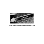
The Prosignia Notebook Family of Personal Computers is a line of multimedia
notebook computers with advanced modularity, processors, and video graphics. This
full-function, Mobile Pentium II-based family of notebook computers allows full
desktop functionality and connectivity through the use of an optional Convenience
Base.
Figure 1-1. Prosignia Notebook Personal Computer
Product Description 1-1
1.1.1 Features
The computer models have the following standard features:
■
■
■
■
■
■
■
■
■
■
■
■
■
■
■
■
■
■
■
233-MHz, 266-MHz, or 300-MHz Mobile Pentium II processors
32-MB or 64-MB of synchronous dynamic random access memory (SDRAM),
expandable to 160 MB (depending on the model)
3.2-, 4.0-, or 6.0-GB, 2.5-inch internal hard drive mounted in carrier
LCD displays:
❏ 12.1 inch SVGA CTFT display
❏ 13.3-inch XGA CTFT display
❏ 14.1-inch XGA CTFT display
Supports Lithium Ion (Li-ion) battery packs
Internal stereo speakers
Internal microphone
1.44-MB diskette drive, DVD, LS-120, Iomega Zip or second battery or Hard Disk
Drive in the Multi-bay adapter
DVD drive or 24X CD-ROM in the Optical Disk Bay
Full-size 101 key compatible keyboard including 12 function keys, 8 cursor control
keys, inverted-T cursor control keys, and embedded numeric keypad
Four user-programmable keys
Touchpad pointing device
Operates from a battery pack in the battery bay, plus an optional battery pack in the
MultiBay, or integrated AC power supply that is compatible with domestic or
international power sources
Power management and security features
Infrared interface for wireless communication with other IrDA-compliant devices at
1
data rates up to 4 mb/sec (available on selected models)
Two standard device slots that will accommodate two Type II or one Type III PC
Card, PCMCIA card or CardBus card. Zoomed-Video is supported in the bottom
slot.
176-pin expansion connector provides the interface to the convenience base options
Rear-panel ports provide connections for parallel, serial, external monitor, and
keyboard/mouse
Universal Serial Bus (USB)
1.1.2 Models
Compaq Prosignia Notebook computers are configurable, and may contain any or all of
the features listed. All models have 32-MB or 64-MB of standard memory with one
32-MB memory module in the memory expansion port, and may be upgraded to 160MB.
1
Windows 95 supports up to 115-kb/sec. Driver for 4 mb/sec available from www.microsoft.com.
1-2 Product Description
1.1.3 Software Fulfillment
Replacement software may be ordered directly from Compaq Computer Corporation.
Both the model and the serial number of the computer are needed to identify the
specific software available.
1.2 Computer Options
The computer supports the following options:
■
■
■
■
■
■
■
■
■
■
■
■
■
■
■
Convenience Base II pass through model with monitor stand
Convenience Base II with Ethernet with monitor stand
Compatible with Convenience Base models from the Armada 1500 Family of
Personal Computers
Memory expansion boards
Li-ion battery pack
Automobile/Aircraft Adapter
External Battery Charger
PCMCIA modem
Hard drive upgrade
Hard drive adapter for MultiBay with carrying case
Internal modem
CD-ROM drive for Optical Disc Bay
DVD-ROM for Optical Disc Bay
120-MB LS-120 diskette drive for MultiBay
100-MB Zip drive for MultiBay
1.2.1 Convenience Base II
Prosignia Notebook models support the following convenience base models:
Convenience Base II pass through
■ Convenience Base II with Ethernet
■
1.2.2 System Memory Options
The computer supports optional 32-, 64-, and 128-MB memory boards. The memory
boards are 66-MHz SDRAM without parity. System memory can be expanded to
160-MB, depending on the model.
Product Description 1-3
1.2.3 External Battery Charger
The external battery charger has the following features:
Two battery charge slots
■ Accepts Li-ion modular batteries
■ Charges 1 battery in 1.5 hours
■ Charges 2 batteries in 3 hours
■
Note: The battery calibration process should be used to discharge the batteries.
1.2.4 External Keyboards and Pointing Devices
Supports Compaq or Compaq compatible PS2 keyboards and pointing devices.
1.2.5 External Monitors
Supports all VGA Monitors at resolutions up to 1280 × 1024
■ Supports DDC1 and DDC2b compliant Energy Star monitors
■
1.3 External Computer Components
The external computer components are illustrated and described in this section.
1-4 Product Description
1.3.1 Left Side Components
The left side external components are shown in Figure 1-2 and are described in Table 11.
Figure 1-2. Left Side Components
Table 1-1
Computer Components
Left Side
Item
Component
Function
1
2
3
4
5
6
Cable Lock
Speaker/headphone jack
Microphone jack
Volume up
Volume down
Left bass reflex speaker port
Secures computer to fixed object
Connects stereo speakers, headphone or headset
Connects external microphone, disables internal microphone
Increases volume
Decreases volume
Enhances audio quality
Product Description 1-5
1.3.2 Front Components
The front external components are shown in Figure 1-3 and are described in Table 1-2.
Figure 1-3. Front Components
Table 1-2
Computer Components
Front
Item
Component
Function
1
2
3
4
Display
Lid switch
Speakers
MultiBay
5
6
7
8
Optical disc bay
Battery bay
Keyboard
Microphone
LCD graphic display
Blanks display when display is closed
Produce high quality stereo sound
Accepts diskette drive, LS-120 drive, ZIP drive, second battery
pack or second hard drive
Accepts CD-ROM or DVD-ROM drives
Accepts Li-Ion battery pack
Accepts operator input
Monophonic microphone
1-6 Product Description
1.3.3 Top Components
The top external components are shown in Figure 1-4 and are described in Table 1-3.
Figure 1-4. Top Components
Table 1-3
Computer Components
Top
Item
Component
Function
1
2
3
4
5
6
Lid switch
Programmable function buttons
Suspend button
Power switch
Keyboard release latches
Touchpad
Blanks display when display is closed
User programmable keys
Initiates suspend
Turns power on and off
Releases keyboard from system unit
Pointing device
Product Description 1-7
1.3.4 Right Side Components
The right side external components are shown in Figure 1-5 and are described in
Table 1-4.
Figure 1-5. Right Side Components
Table 1-4
Computer Components
Right Side
Item
Component
Function
1
2
3
4
5
Right bass reflex speaker port
PC Card eject button
PC Card slots
USB Connector
Modem jack
Enhances audio quality
Eject PC Cards from the slots
Accepts 16- and 32-bit PC Cards
Connects USB devices to the computer
Connects the phone line to the computer (selected models)
1-8 Product Description
1.3.5 Rear Components
The rear components are shown Figure 1-6 and are described in Table 1-5.
Figure 1-6. Rear Components
Table 1-5
Computer Components
Rear
Item
Component
Function
1
2
3
4
5
6
7
8
Parallel connector
Serial connector
Infrared port
External monitor connector
AC Power connector
Docking connector
Fan (Airflow vents)
External keyboard connector
Connects parallel devices such as a printer
Connects serial devices such as a mouse
Provides wireless communications (on selected models)
Connects external monitor
Connects external AC power
Provides connection to optional convenience base
Provides thermal ventilation to internal components
Connects external keyboard or PS-2 mouse
(Supports standard Y connector)
Product Description 1-9
1.3.6 Bottom Components
The bottom external components are shown in Figure 1-7 and are described in
Table 1-6.
Figure 1-7. Bottom Components
Table 1-6
Computer Components
Bottom
Item
Component
Function
1
2
3
4
5
6
*
Modem compartment
Docking latch receptacles
Docking alignment guide
Tilt feet
MultiBay screw
Hard drive cover
Hard drive security screw
Integrated modem (selected models)
Locks computer to optional convenience base
Aligns computer to optional convenience base
Adjusts computer to an angle
Secures MultiBay Devices
Covers hard drive compartment
Secures hard drive cover (not shown)
1-10 Product Description
1.3.7 Status Panel Lights
The status panel lights are shown in Figure 1-8 and described in
Table 1-7.
Figure 1-8. Status Panel Lights
Table 1-7
Computer Components
Status Panel
Item
Component
Function
1
2
3
4
5
Hard drive activity light
MultiBay activity light
Number lock indicator
Caps lock indicator
Scroll lock indicator
Indicates hard drive or CD-ROM access
Indicates Multi-Bay device activity
Indicates that numbers lock is on
Indicates that caps lock is on
Indicates that scroll lock is on
Product Description 1-11
1.4 Design Overview
This section presents a design overview of the computer. The overview is limited to
field replaceable parts. All replacement parts are listed in Chapter 3.
1.4.1 System Unit
The computer is a traditional clamshell design with a display assembly attached to a
system unit. The computer opens to reveal a backlit LCD display and a full-function
keyboard. The display is designed for a continuously adjustable tilt angle.
1.4.2 Internal Boards
The system electronics are integrated on four printed circuit assemblies: the audio/led
board, system board, modem board, and the DC-DC converter board.
The audio/led board provides support for the audio functions.
■ The system board integrates the processor, on-board memory, level 2 cache, local
bus video adapter, and PCMCIA/CardBus adapter.
■ The optional modem board supports data or fax functions.
■ The DC-DC converter board creates the system voltages (3.3 VDC and 5 VDC)
from the battery or AC/DC input.
■
Processor
An Intel Mobile Pentium II processor is located on the system board for the 233 MHz,
266 MHz, or 300 MHz models.
Memory
Base memory is 32-MB with 32-, 64-, or 128-MB of optional expansion memory. Base
memory is onboard memory built into the system board. Expansion memory consists of
one memory expansion board available as a user installable option. Some models come
standard with 64-MB of total memory. This consists of 32-MB of standard memory
and 32-MB of additional memory in the memory expansion unit.
Cache
Level 2 cache is integrated in the CPU module. It is not user upgradable.
1-12 Product Description
PCMCIA/CardBus and Video Adapter Controller
The PCMCIA/CardBus adapter is based on the Texas Instrument PCI1220 PC to
CardBus controller unit. The local bus video adapter is the Chips and Technologies
65555 controller.
The serial-parallel port board expands the serial and parallel signals from the system
board to the serial and parallel expansion connectors.
■ The audio/led board supports the microphone and headphone jacks, the volume
control switches, and the amplifier and equalization circuitry.
■
1.4.3 Video system
The standard video subsystem consists of:
■
■
■
■
■
■
■
■
An internal LCD Display
12.1 inch SVGA CTFT display
13.3 inch XGA CTFT display
14.1 inch XGA CTFT display
2 Megabyte frame buffer
An inverter to supply AC power to the LCD back-light system
A standard external VGA connector for use with CRTs and other VGA compatible
displays
40 KByte Video ROM
Product Description 1-13
chapter
2
T ROUBLESHOOTING
Follow these basic steps when beginning the troubleshooting process:
1.
2.
3.
4.
5.
Complete the preliminary steps listed in Section 2.1.
Run the Power-On Self-Test (POST) as described in Section 2.3.
Run Computer Setup as described in Section 2.5.
Run the Computer Checkup (TEST) as described in Section 2.6.
If you are unable to run POST or Computer Checkup or if the problem persists
after running POST and Computer Checkup, perform the recommended actions
described in the diagnostic tables in Section 2.5.
Follow these guidelines when troubleshooting:
■
■
■
■
■
Complete the recommended actions in the order in which they are given.
Repeat POST and Computer Checkup after each recommended action until the
problem is resolved and the error message does not return.
When the problem is resolved, stop performing the troubleshooting steps and do not
complete the remaining recommended actions.
Refer to Chapter 5 for removal and replacement procedures that are recommended.
If the problem is intermittent, check the computer several times to verify that the
problem is solved.
The following table describes the troubleshooting actions:
Table 2-1
Trouble Shooting Actions
If You Want To:
Then Run:
Check for POST error messages
Check that computer components are recognized and
running properly
View information about the computer and installed or
connected devices
Perform any of the following:
■ Check the system configuration
■ Set the system power management parameters
■ Return the system to its original configuration
■ Check system configuration of installed devices
POST
Computer Checkup (TEST) under Compaq Utilities
View System Information (INSPECT) under Compaq
Utilities
Computer Setup
Troubleshooting 2-1
2.1 Preliminary Steps
IMPORTANT: Use AC power when running POST, Computer Setup, or Computer
Checkup. A low battery condition could initiate Hibernation and interrupt the test.
Before running POST and Computer Checkup, complete the following steps:
1. Obtain established passwords. If you must clear the passwords, go to Section 2.2.
2. Ensure that the hard drive is installed in the computer.
3. Ensure that the battery pack is installed in the computer and the power cord is
connected to the computer and plugged into an AC power source.
4. Turn on the computer.
5. If a power-on password has been established, type the password and press Enter.
6. Run Computer Setup (Section 2.5). If a Setup password has been established, type
the password and press Enter.
7. Turn off the computer and all external devices.
8. Disconnect external devices that you do not want to test. If you want to use the
printer to log error messages, leave it connected to the computer.
NOTE: If a problem only occurs when an external device is connected to the
computer, the problem could be with the external device or its cable. Isolate the
problem by running POST with and without the external device connected.
9. Use Compaq Utilities and Loopback plugs in the serial and parallel connectors if
you plan to test these ports.
Follow these steps to run Compaq Utilities:
a. If you are running Compaq Utilities from the hard drive, turn on or restart the
computer. Press F10 when the cursor appears in the upper right corner of the
screen. If you do not press F10 in time, restart the computer and try again.
If you are running Compaq Utilities from diskette, insert the Compaq Utilities
diskette in drive A. Turn on or restart the computer.
b. Press Enter to accept OK.
c. Select Computer Checkup (TEST).
d. Select Prompted Diagnostics.
e. After “Identifying System Hardware” completes, select Interactive Testing and
follow the instructions on the screen.
2-2 Troubleshooting
2.2 Clearing Passwords
The power-on password prevents use of the computer until the password is entered.
The setup password prevents unauthorized changes to Computer Setup. To clear the
passwords, you must remove all power from the system board. If you do not know the
passwords, use the following procedure to clear the password:
1.
2.
3.
4.
5.
6.
Remove all battery packs from the battery bay and MultiBay, if applicable.
Disconnect the AC power.
Remove the real-time clock battery.
Wait five minutes.
Reconnect the AC power.
Restart the computer. During Power-On Self Test (POST), a “162 System Options
not set” message appears.
7. Shut down the computer, then disconnect AC power again.
8. Replace the real-time clock battery.
9. Install the battery pack(s).
Proceed with the troubleshooting procedures.
2.3 Power-On Self-Test (POST)
The Power-On Self-Test (POST) is a series of tests that run every time the computer is
turned on. POST verifies that the system is configured and functioning properly.
To run POST, complete the following steps:
1. Complete the preliminary steps (Section 2.1).
2. Turn on the computer.
If POST does not detect any errors, the computer beeps once or twice to indicate that
POST has run successfully. The computer boots from the hard drive or from a bootable
diskette if one is installed in the diskette drive.
Troubleshooting 2-3
2.4 POST Error Messages
If the system is not functioning well enough to run POST, or if the display is not
functioning well enough to show POST error messages, refer to the Troubleshooting
tables in Section 2.6.
If POST detects an error, one of the following events occurs:
A message with the prefix "WARNING" appears informing you where the error
occurred. The system pauses until you press F1 to continue.
■ A message with the prefix "FATAL" appears informing you where the error
occurred. After the message, the system emits a series of beeps and stops.
■ The system emits a series of beeps and stops.
■
Warning messages indicate that a potential problem, such as a system configuration
error, exists. When F1 is pressed, the system should resume. You should be able to
correct problems that produce WARNING messages.
IMPORTANT: When a WARNING message includes the prompt to "RUN SCU," press
F10 to run Computer Setup. (Computer Setup replaces the SCU utility.)
2-4 Troubleshooting
If you receive one of the error messages listed in Table 2-2, follow the recommended
action.
Table 2-2
Warning Messages
Message
Description
CMOS checksum invalid, run SCU
CMOS RAM information has been
corrupted.
CMOS RAM has lost power.
CMOS failure, run SCU
Diskette controller error
Recommended Action
Run Computer Setup to reinitialize
CMOS-RAM.
Run Computer Setup to reinitialize
CMOS-RAM.
The diskette drive controller failed If there is no diskette drive in the
to respond to the recalibrate
system, run Computer Setup to
command.
properly configure the CMOS-RAM
to show no diskette drive present. If
the problem persists, or if a diskette
drive is present, complete these
steps until the problems is solved:
1. Check diskette drive connections.
2. Replace diskette drive.
3. Replace system board.
Diskette track 0 failed
The diskette drive cannot read
track 0 of the diskette in the drive.
Hard disk controller error
The hard drive controller failed to
respond to the reset command.
Keyboard controller failure
The keyboard failed the self-test
command.
The keyboard failed to respond to
the RESET ID command.
Keyboard failure
No interrupts from Timer 0
ROM at xxxx (LENGTH yyyy) with
nonzero checksum (zz)
Time/Date corrupt - run SCU
Try another diskette. If the problem
persists, you may need to replace
the diskette drive.
Check the drive parameters. Turn
off the system and check all related
connections.
Replace the system board.
Replace the keyboard. If the
problem persists, replace the
system board.
Replace the system board.
The periodic timer interrupt is not
occurring.
An illegal adapter ROM was located Check the external adapter (such as
at the specified address.
a video card) to determine if it is
causing the conflict.
The time and date stored in the
1. Run Computer Setup.
real time clock have been
2. If problem persists, replace
corrupted, possibly by a power
auxiliary battery.
loss.
3. If problems persists, replace
system board.
Hard disk xx failure (or error)
A failure or an error occurred when 1. Run Scan disk.
trying to access the hard drive.
2. Check disk in DOS and
Windows 95. If problem persists,
refer to Table 2-11.
Unsupported memory module
An EDO memory module was
installed in the memory expansion
slot.
Remove the EDO memory module
and replace with SDRAM memory
module.
Troubleshooting 2-5
Fatal errors emit a beep and may display a FATAL message. Fatal errors indicate severe problems, such as a hardware failure. Fatal errors do not allow the
system to resume. Some of the Fatal error beep codes are listed at the end of this section.
Table 2-3
Fatal Error Messages
Message
Description
Beep Code
CMOS RAM test failed
A walking bit test of CMOS RAM location 0E
(Hex) - 3F (Hex) failed.
A sequential read/write of the transfer count
and transfer address registers within the
primary and secondary DMA controllers failed.
A walking bit read/write of the 16 DMA
controller page registers starting at location
80 Hex failed.
A continuous read/write test of port 61h found
that bit 4 (Refresh Detect) failed to toggle
within an allotted amount of time.
A sequential read/write of various Interrupt
Controller registers failed.
A checksum of the ROM BIOS does not match
the byte value at F000:FFFF.
RAM error occurred during memory test.
3
DMA controller faulty
Faulty DMA page registers
Faulty refresh circuits
Interrupt controller failed
ROM checksum incorrect
RAM error at location xxxx
4
0
1
5
2
None
Table 2-4
Fatal Error Beep Codes
Beep Code Beep Sequence
Description
Recommended Action
0
S-S-S-P-S-S-L-P
Replace system board.
1
2
3
4
5
6
7
8
S-S-S-P-S-L-S-P
S-S-S-P-S-L-L-P
S-S-S-P-L-S-S-P
S-S-S-P-L-S-L-P
S-S-S-P-L-L-S-P
S-S-S-P-L-L-L-P
S-S-L-P-S-S-S-P
S-S-L-P-S-S-L-P
The DMA page registers are
faulty.
The refresh circuitry is faulty.
The ROM checksum is incorrect.
The CMOS RAM test failed.
The DMA controller is faulty.
The interrupt controller failed.
The keyboard controller failed.
Graphics adapter is faulty.
Internal RAM is faulty.
S = Short, L = Long, P = Pause
2-6 Troubleshooting
Replace memory board or
system board if memory on
system board is faulty.
2.5 Compaq Utilities
Compaq Utilities contain several functions that
■ Determine if various computer devices are recognized by the system and are
operating properly.
■ Provide information about the system once it is configured.
Compaq Utilities include the following programs:
■ Computer Setup
■ Computer Checkup (TEST)
■ View System Information (INSPECT)
To access Compaq Utilities:
1. Turn on or restart the computer by clicking Start ⇒ Shut Down ⇒ Restart the
computer.
2. Press F10 when the blinking cursor appears in the upper-right corner of the display.
3. Select a menu option.
2.5.1 Computer Setup
Computer Setup contains utilities that give you an overall picture of the computer
hardware configuration and aid in troubleshooting. These utilities also allow you to set
custom features such as security options, power conservation levels, and startup
preferences.
If you are running Windows 95, the computer automatically recognizes and configures
the system for new devices. If you have a configuration problem or want to view or
reset configuration settings, you can use Computer Setup.
NOTE: If you are running Windows 95, you should use Computer Setup only to adjust
system features such as the power-on password or battery conservation level. Windows
95 may override other configuration changes.
If you are running Windows NT, the computer does not automatically recognize new
devices added to the system. All devices ordered with your system have been
configured for you. Use Computer Setup to view settings for a new device you have
added or to reset configuration settings for preinstalled devices.
Computer Setup provides two methods of viewing the computer configuration: by type
(factory setting) or connection.
Categories by type:
■ System Features—security, power, boot management
■ Communication—port, modem, and other communication devices
■ Storage—storage-related devices such as hard drive, CD-ROM drive, diskette drive
■ Input Devices—keyboard, mouse, and other input devices
■ Network—network adapter or other network-related devices
■ Audio—sound properties and audio device settings
■ Video—display timeouts and video device resources
■ Other—miscellaneous devices
Troubleshooting 2-7
Categories by connection:
■
■
■
■
■
System Features—security, power, boot management
System Devices—keyboard, mouse, parallel and serial ports
ISA—ISA bus and connected devices
PCI—PCI bus and connected devices
PC Card—PC Card devices
Running Computer Setup
1. Turn on or restart the computer by clicking Start ⇒ Shut Down ⇒ Restart the
computer.
2. Press F10 when the blinking cursor appears in the upper-right corner of the screen.
NOTE: If you a setup password is enabled, it must be used to access Computer Setup.
3. Click a language and press Enter.
4. Click Computer Setup and press Enter.
5. When you are finished, click Exit.
Exiting Computer Setup
1. Click Exit.
2. Select one of the following Exit options:
■ Save—Saves the new settings and exits Computer Setup.
NOTE: Some settings may not take effect until the computer is restarted.
Ignore—Exits Computer Setup and restores previous settings.
■ Cancel—Returns to Computer Setup.
■
2-8 Troubleshooting
2.5.2 Computer Checkup (TEST)
Computer Checkup (TEST) determines whether the various computer components and
devices are recognized by the computer and are functioning properly. You can display,
print, or save the information that Computer Checkup generates.
NOTE: Compaq Utilities are intended for testing only Compaq-supplied components.
Testing of non-Compaq components may be inconclusive.
Running Computer Checkup (TEST)
1. Plug the computer into an external power source. A low battery condition can
interrupt the program.
2. Connect a printer if you want to print a log of error messages.
3. Turn on the external devices that you want to test.
4. Turn on or restart the computer.
5. Access Compaq Utilities by pressing F10 when the blinking cursor appears in the
upper-right corner of the display.
6. Click Computer Checkup ⇒ View the Device List.
■ If the list of installed devices is correct, click OK.
■ If the list is incorrect, ensure that any new devices are installed properly.
7. Select one of the following from the Test Option menu:
■ Quick Check Diagnostics
■
Automatic Diagnostics
■
Prompted Diagnostics
8. Follow the instructions on the screen as the devices are tested.
9. Click Exit Diagnostics ⇒ Exit from this utility.
Computer Checkup (TEST) Error Codes
Computer Checkup (TEST) error codes occur if the system recognizes a problem while
running Computer Checkup. These error codes help identify possible defective
assemblies. Table 2-5 through Table 2-15 list Computer Checkup error codes, a
description of the error condition, and the recommended action for resolving the
condition. For removal and replacement procedures, refer to Chapter 5.
IMPORTANT: Run Computer Checkup each time you complete a recommended action
step. If the problem is resolved when POST and Computer Checkup are rerun (i.e.,
with no error codes), do not perform the remaining recommended action steps.
NOTE: The error codes in the following tables are listed in an “AYE-XX” format,
where:
A or AA
= Number that represents the faulty assembly
YY
= Test or action that failed
XX
= Specific problem
Troubleshooting 2-9
Table 2-5
Processor Test Error Codes
Error Code Description
Recommended Action
101-xx
103-xx
104-xx
105-xx
106-xx
107-xx
108-xx
109-xx
110-xx
113-xx
Replace the processor board and retest.
Replace the system board and retest.
CPU test failed.
DMA page registers test failed.
Interrupt controller master test failed.
Port 61 error.
Keyboard controller self-test failed.
CMOS RAM test failed.
CMOS interrupt test failed.
CMOS clock test failed.
Programmable timer load data test failed.
Protected mode test failed.
Table 2-6
Memory Test Error Codes
Error Code Description
Recommended Action
200-xx
Memory machine ID test failed.
202-xx
Memory system CMOS checksum failed.
203-xx
Write/Read test failed.
204-xx
Address test failed.
The following steps apply to error codes 200-xx
and 202-xx:
1. Flush the system CMOS and retest. See note.
2. Replace the system board and retest.
The following applies to error codes 203-xx
through 215-xx:
Remove and replace the SODIMM memory board
or system board (if the memory on the system
board is faulty) and retest.
211-xx
214-xx
215-xx
Random pattern test failed.
Noise test failed.
Random address test failed.
Table 2-7
Keyboard Test Error Codes
Error Code Description
Recommended Action
300-xx
301-xx
302-xx
304-xx
1. Reseat the keyboard assembly.
2. Replace the keyboard and retest.
3. Replace the system board and retest.
Failed ID Test.
Failed Self test/Interface Test.
Failed Individual Key Test.
Failed Keyboard Repeat Test.
Table 2-8
Parallel Printer Test Error Codes
Error Code Description
Recommended Action
401-xx
402-xx
403-xx
1. Connect the printer.
2. Check power to the printer.
3. Install the loopback connector and retest.
4. Check port and IRQ configuration.
5. Replace the system board and retest.
2-10 Troubleshooting
Printer failed or not connected.
Failed Port Test.
Printer pattern test failed.
Note: Fn + F11 clears the ESCD configuration information. If the Fn + F11 sequence is
pressed very early after powering the machine on (after you see the keyboard LEDs
blink, but before the video is initialized), CMOS memory will be invalidated. The
ESCD is cleared, the machine is reset and boots with the "162 - System Options Not
Set" message. This is a way to clear out configuration information, such as the
Windows 95 knowledge about a docking station. It may help clear up problems if the
configuration information had been corrupted. Timing of this keystroke sequence is
critical, as there is a very narrow window during which the keys will be recognized.
These keys are not documented to users.
Table 2-9
Diskette Drive Error Codes
Error Code
Description
Recommended Action
600-xx
601-xx
Diskette ID drive types test
failed.
Diskette format failed.
The following steps apply to error codes 600-xx
through 698-xx:
1. Replace the diskette.
602-xx
Diskette read test failed.
2. Replace the diskette drive and retest.
603-xx
Diskette write, read, compare test failed.
3. Replace the system board and retest.
604-xx
605-xx
606-xx
609-xx
610-xx
697-xx
698-xx
699-xx
Diskette random read test failed.
Diskette ID media test failed.
Diskette speed test failed.
Diskette reset controller test failed.
Diskette change line test failed.
Diskette type error.
Diskette drive speed not within limits.
Diskette drive/media ID error.
1. Replace media.
2. Run Compaq Utilities.
Table 2-10
Serial Test Error Codes
Error Code
Description
Recommended Action
1101-xx
Serial port test failed.
1. Check port configuration.
2. Replace the system board and retest.
Troubleshooting 2-11
Table 2-11
Hard Drive Test Error Codes
Error Code
Description
Recommended Action
1701-xx
Hard drive format test failed.
1. Run Compaq Utilities and verify drive type.
1702-xx
Hard drive read test failed.
2. Verify that all secondary drives have
secondary drive capability.
1703-xx
Hard drive write/read/compare test failed. 3. Replace the hard drive and retest.
Hard drive random seek test failed.
4. Replace the system board and retest.
1704-xx
1705-xx
Hard drive controller test failed.
1706-xx
Hard drive ready test failed.
1707-xx
Hard drive recalibration test failed.
1708-xx
Hard drive format bad track test failed.
1709-xx
Hard drive reset controller test failed.
1710-xx
Hard drive park head test failed.
1715-xx
Hard drive head select test failed.
1716-xx
Hard drive conditional format test failed.
1717-xx
Hard drive ECC* test failed.
1719-xx
Hard drive power mode test failed.
1724-xx
Network preparation test failed.
1736-xx
Drive monitoring test failed.
* ECC = Error Correction Code
Table 2-12
Video Test Error Codes
Error Code Description
Recommended Action
501-xx
Video controller test failed.
502-xx
Video memory test failed.
The following actions apply to error codes 501-xx
through 516-xx:
1. Disconnect external monitor and test with
internal LCD display.
503-xx
Video attribute test failed.
2. Replace the display assembly and retest.
504-xx
Video character set test failed.
3. Replace the system board and retest.
505-xx
507-xx
511-xx
512-xx
514-xx
516-xx
2402-xx
Video 80 × 25 mode 9 × 14 character
cell test failed.
Video 80 × 25 mode 8 × 8 character
cell test failed.
Video 40 × 25 mode test failed.
Video screen memory page test failed.
Video gray scale test failed.
Video white screen test failed.
Video noise pattern test failed.
Video memory test failed.
2403-xx
Video attribute test failed.
2404-xx
Video character set test failed.
2405-xx
Video 80 × 25 mode 9 × 14 character cell 3. Replace the display assembly and retest.
test failed.
4. Replace the system board and retest.
506-xx
The following actions apply to error codes
2402-xx through 2456-xx:
1. Run Compaq Utilities.
2. Disconnect external monitor and test with
internal LCD display.
Continued
2-12 Troubleshooting
Table 2-12 Video Test Error Codes Continued
Error Code Description
Recommended Action
2406-xx
Video 80 × 25 mode 8 × 8 character cell
test failed.
2411-xx
Video screen memory page test failed.
2412-xx
Video gray scale test failed.
2414-xx
Video white screen test failed.
2416-xx
Video noise pattern test failed.
2418-xx
ECG/VGC memory test failed.
2419-xx
ECG/VGC ROM checksum test failed.
2421-xx
ECG/VGC 640 × 200 graphics mode test
failed.
2422-xx
ECG/VGC 640 × 350 16 color set test
failed.
2423-xx
ECG/VGC 640 × 350 64 color set test
failed.
2424-xx
ECG/VGC monochrome text mode test
failed.
2425-xx
ECG/VGC monochrome graphics mode test
failed.
2431-xx
640 × 480 graphics test failed.
2448-xx
Advanced VGA Controller test failed.
2451-xx
132-column Advanced VGA test failed.
2456-xx
Advanced VGA 256 Color test failed.
2458-xx
Advanced VGA Bit BLT test failed.
The following step action to error codes 2458-xx
to 2480-xx:
2468-xx
Advanced VGA DAC test failed.
Replace the system board and retest.
2477-xx
Advanced VGA data path test failed.
2478-xx
Advanced VGA BitBLT test failed.
2480-xx
Advanced VGA Linedraw test failed.
Refer to Table 2-26 for information about other video errors.
Table 2-13
Audio Test Error Codes
Error Code Description
Recommended Action
114-01
1. Check system configuration.
Speaker test failed.
2. Verify that the audio/led board is properly
seated.
3206-xx
Audio System Internal Error
3. Verify display audio cable connection.
Replace the audio board and retest.
Table 2-14
Pointing Device Interface Test Error Codes
Error Code Description
Recommended Action
8601-xx
8602-xx
Replace the keyboard/CPU cover assembly.
Pointing device test failed.
Interface test failed.
Troubleshooting 2-13
Table 2-15
CD-ROM Test Error Codes
Error Code Description
Recommended Action
3301-xx
1. Replace the CD and retest.
CD-ROM drive read test failed.
2. Verify that drivers are loaded and properly
installed.
3305-xx
CD-ROM drive seek test failed.
6600-xx
6605-xx
6608-xx
6623-xx
ID test failed.
Read test failed.
Controller test failed.
Random read test failed.
3. Replace the CD-ROM drive and retest.
4. Replace the system board and retest.
2.5.3 Running View System Information (INSPECT)
The View System Information (INSPECT) utility provides information about the
computer and installed or connected devices. You can display, print, or save the
information.
In order to access the INSPECT utility, follow the instructions below:
1. Connect a printer if you want to print the INSPECT information.
2. Turn on or restart the computer.
3. Access Compaq Utilities by pressing F10 when the cursor blinks in the upper-right
corner of the display.
4. If prompted, select a language.
5. Click View System Information (INSPECT).
6. Click the item you want to view. The list includes the following:
■
■
■
■
■
■
■
System
ROM
Keyboard
System ports
System storage
Graphics
Memory
■
■
■
■
■
■
Audio
Operating system
System files
Windows files
Miscellaneous
Network - Applicable only if
computer is docked in the
1
Convenience Base II
7. Follow the instructions on the screen to cycle through the screens, to return to the
list and choose another item, or to print the information.
8. Select Exit Inspect.
1
The Compaq Prosignia is only supported by Convenience Base II. It is not supported by any prior convenience bases.
2-14 Troubleshooting
2.5.4 Running Compaq Diagnostics
Compaq Diagnostics provides computer component information when the operating
system is working.
If you are running Windows 95, access Compaq Diagnostics for Windows by
double-clicking My Computer ⇒ Control Panel ⇒ Compaq Diagnostics.
2.5.5 Boot Sequencing
1.
2.
3.
4.
Run Computer Setup.
Click the System Features icon ⇒ Boot Management box ⇒ MultiBoot tab.
Designate the hard drive boot (startup) sequence you want.
Click OK to accept the changes.
Troubleshooting 2-15
2.5.6 Factory Default Settings
Initialization
Enable POST Memory Test
Keyboard num Lock
1
2
Boot display
Language
Checked (enabled)
Unchecked (Off)
Hard drive in the computer
Hard drive in the computer MultiBay
Auto
Language of country
Ports
Serial/infrared ports
Serial port
Infrared port
Parallel port
Ethernet port
3F8, IRQ4
2F8, IRQ3
378, IRQ7
300, IRQ9
Power
Low Battery Warning Beep
External Energy Saving Monitor Connected
Power Management
Enabled
Conservation Level
Level Definition
High
Medium
Custom
Checked (enabled)
Unchecked (not connected)
While operating power on battery
Medium
Suspend Time: 5 minutes
Hibernation Timeout: Immediate
Drive Timeout: 2 minutes
Screen Timeout: 2 minutes
Suspend Time: 10 minutes
Hibernation Timeout: 1 hour
Drive Timeout: 6 minutes
Screen Timeout: 4 minutes
Suspend Time: disabled
Hibernation Timeout: low battery
Drive Timeout: always on
Screen Timeout: always on
Security
Enable QuickLock/QuickBlank
Enable Power-On Password
Disable Serial/Infrared Ports
Disable Parallel Port
Disable PC Card Slots
Setup Password
Power-On Password
Diskette Drives
Disable Diskette Drives
Disable Diskette Boot
2-16 Troubleshooting
Unchecked (Disabled)
Unchecked (Disabled)
Unchecked (Enabled)
Unchecked (Enabled)
Unchecked (Enabled)
Password blank
Password blank
Unchecked (Enabled)
Unchecked (Enabled)
2.6 Troubleshooting Without Diagnostics
This section provides information about how to identify and correct some common
hardware, memory, and software problems. It also explains several types of messages
that may be displayed on the screen.
Since symptoms can appear to be similar, carefully match the symptoms of the
computer malfunction against the problem description in the Troubleshooting tables to
avoid a misdiagnosis.
2.6.1 Before Replacing Parts
When troubleshooting a problem, check the following items for possible solutions
before replacing parts:
Verify that cables are connected properly to the suspected defective parts.
■ Verify that all required device drivers are installed.
■ Verify that all printer drivers have been installed.
■
2.6.2 Checklist for Solving Problems
If you encounter a minor problem with the computer or software applications, go
through the following checklist for possible solutions:
■
■
■
■
■
Is the computer connected to an external power source, or does it have a fully
charged battery pack installed?
Are all cables connected properly and securely?
Did the diskette drive contain a nonbootable diskette when you turned on the
computer?
Have you installed all the needed device drivers? For example, if you are using a
mouse, you may need to install a mouse device driver.
Are printer drivers installed?
Eliminating the typical problems described in this Troubleshooting section may save
you time and money. If the problem appears related to a software application, check
the documentation provided with the software. You may discover something you can
resolve easily by yourself.
Troubleshooting 2-17
Solving Audio Problems
Table 2-16
Solving Audio Problems
Problem
Probable Cause
Recommended Action(s)
Computer does not beep after Speaker volume has been
the Power-On Self-Test
turned down.
(POST).
Adjust the volume with the volume control
buttons located at the top right corner of the
computer.
Computer beeped five times
and battery light is blinking.
Computer does not beep to
indicate a low-battery
condition.
Immediately save open files and resolve the
low battery condition.
Enable low-battery warning beeps in
Windows 95 Power Properties or in
Computer Setup power management.
Press Fn+F5, then press the right arrow key
to increase the volume of the system beeps.
In Windows 95, adjust the computer volume
control buttons and adjust the volume
control in Multimedia Properties.
NOTE: The volume control in Multimedia
Properties only affects the “Wave” audio
sources such as system sounds and *.wav
file playback. To change other sources such
as MIDI, video sound, and game effects, use
the Volume Control application in
accessories/Multimedia.
In Windows NT, adjust the multimedia
volume control under the Accessories
folder.
Press the increase volume control button to
increase the volume. Press Fn+F5, then
press the right arrow key to increase the
volume of the system beeps
Use the external speakers or headphones or
use the Convenience Base II speakers.
To use the internal speakers, disconnect the
external speakers or headphones or undock
the computer.
Make sure the speaker wires are connected
properly.
Replace the speakers.
Audio playback is too low or
too loud.
Internal speakers produce no
sound.
Computer has entered a
low-battery condition.
Low-battery warning beeps
have been turned off.
System beeps have been
turned down too low.
The computer volume control
and/or the software volume
control needs to be adjusted.
Volume has been muted.
External speakers or
headphones are connected to
the computer.
Speaker wires are not
connected.
Speakers are bad.
Continued
2-18 Troubleshooting
Table 2-16 Solving Audio Problems Continued
Problem
Probable Cause
Recommended Action(s)
Internal speaker does not
produce sound when an
external audio source is
connected to the stereo
line-in jack.
Volume may be turned off or
set too low.
Adjust the volume control located at the top
right corner of the computer.
Use the volume control and mixing features
available in Control Panel ⇒ Multimedia.
Adjust the volume using the speaker icon on
the taskbar.
Check line input connection.
External microphone does
not work.
No sound from game
program.
No sound from headphones.
Line input may not be
connected properly.
Headphones or speakers are
connected to the stereo
speaker/headphone jack,
which disables the internal
speakers.
The wrong type of
microphone or microphone
plug is being used.
The microphone may not be
connected properly.
Sound source is not selected.
Audio settings are not set
correctly.
Computer volume control is
turned down.
Headphones are connected.
Volume or mixing controls set
incorrectly.
Sound source not selected.
Volume or mixing controls set
incorrectly.
Disconnect the headphones or speakers to
enable the internal speakers.
Check to see if a monophonic electret
condenser microphone with a 3.5-mm plug
is being used.
Ensure that the microphone plug is properly
connected to the mono microphone jack.
Ensure that microphone is selected as the
recording source in Control Panel ⇒
Multimedia and that the recording level is
adjusted.
Check the game program audio settings.
Adjust the volume with the volume control
buttons located at the top right corner of
the computer.
Use or disconnect the headphones.
Adjust the volume with the volume control
buttons located at the top right corner of the
computer.
Use the volume control and mixing features
available in Control Panel ⇒ Multimedia.
Verify that the sound source is selected in
Control Panel ⇒ Multimedia.
Adjust the volume with the volume control
buttons located on the right side of the
computer.
Check the volume and mixer controls in
Control Panel ⇒ Multimedia.
Troubleshooting 2-19
Solving Battery Problems
The following table lists some common battery problems and recommended actions to
take when they occur. The "Solving Power Problems" section in this chapter also may
be applicable.
Table 2-17
Solving Battery and Battery Gauge Problems
Problem
Probable Cause
Recommended Action(s)
The computer turns on the
first time it is used, but the
battery does not charge.
Computer does not turn on
when battery pack is inserted
and power cord is unplugged.
The battery pack is in
ship mode.
Remove and reinsert the battery pack.
Computer beeped five times
and battery light is blinking.
Computer battery light blinks
to indicate low battery
condition, but computer does
not beep.
Battery light does not turn on
to indicate battery pack Is
charging.
Battery pack is warm to the
touch after charging.
Battery is discharged.
Ensure that the battery pack is
properly installed.
Connect the computer to an external power
source and charge the battery pack.
Replace the battery pack with a fully charged
battery pack.
Check battery status by pressing Fn+F8.
Computer has entered a
Immediately save any open file(s). Then do
low-battery condition.
one of the following:
1. Connect the computer to an external
power source.
2. Turn the computer off and replace the
battery pack.
Low battery beeps were
Run Computer Setup and turn on the low
turned off.
battery warning beeps.
Volume is turned off or turned Press Fn+F5 to adjust the volume of the
down too low.
system warning beeps.
Battery pack is already
No action is necessary.
charged.
Battery pack was exposed to Allow time for the battery pack to return to
temperature extremes.
room temperature.
Battery pack is at the end of
Replace the battery pack.
its life.
Warming occurs during
No action is required.
charging.
Continued
2-20 Troubleshooting
Table 2-17 Solving Battery and Battery Gauge Problems Continued
Problem
Probable Cause
Recommended Action(s)
Computer turned off and
information in memory was
lost when the battery pack
was replaced.
Hibernation was disabled,
Suspend was not initiated, or
AC power was not connected
before the discharged battery
pack was removed.
Real time clock (RTC) battery
is at the end of its life.
To prevent loss of information next time,
initiate Suspend, enable Hibernation, or
connect AC power before changing
batteries..
You have to set the date and
time every time you turn on
the computer.
Battery pack charge does not
last as long as expected.
Replace the RTC battery.
Battery pack is being exposed Keep the battery pack within the
to high temperatures or
recommended operating temperature range
extremely cold temperatures. 50°F to 104°F (10°C to 40°C) or
recommended storage range -4°F to 86°F
(-20°C to 30°C ). Recharge the battery pack.
Battery pack has partially
If the computer is disconnected from the
self-discharged.
external power for more than two weeks,
remove the battery pack to reduce the selfdischarge rate.
Power management is
Press Fn+F7 and set the power conservation
disabled.
level.
An external device or PC Card Turn off or disconnect external devices when
is draining the battery.
not using them.
Computer is beeping and
Battery pack charge is low.
Do one of the following:
battery power light is blinking.
Charge the battery pack.
Replace the battery pack.
Connect the computer to an external power
source.
Initiate Hibernation.
Solving CD-ROM Drive Problems
Table 2-18
Solving CD-ROM Drive Problems
Problem
Probable Cause
Recommended Action(s)
CD-ROM drive cannot read a
compact disc.
Compact disc is not properly
seated in the CD-ROM drive.
Compact disc is loaded in the
CD loading tray upside down.
Open the CD loading tray, lay the compact
disc on it, then close the tray.
Open the CD loading tray, turn over the
compact disc (label facing up), then close
the tray.
Insert a different compact disc.
CD-ROM drive is not
recognized by the computer.
Compact disc has a scratch
on its surface.
CD-ROM drive is not
connected properly.
Turn off the computer, remove the CD-ROM
drive and reinsert it.
Troubleshooting 2-21
Solving Diskette and Diskette Drive Problems
Table 2-19
Solving Diskette and Diskette Drive Problems
Problem
Probable Cause
Recommended Action(s)
Diskette drive cannot read a
diskette.
Diskette media has a bad
sector.
Copy remaining files to the hard drive or
another formatted diskette. Reformat the
diskette.
Use the required diskette type.
Using the wrong diskette type
for the diskette drive type.
Diskette is not formatted.
Diskette drive cannot write to
a diskette.
Diskette is not formatted.
Diskette is write-protected.
Writing to the wrong drive.
Not enough space is left on
the diskette.
Disable diskette write ability
is turned on.
2-22 Troubleshooting
Format the diskette.
If you are using Windows 95:
From the Windows 95 desktop, double-click
My Computer.
Click 3 ½ Floppy (A:) ⇒ File ⇒ Format.
Fill in the appropriate information, then click
Start.
If you are using Windows NT, format the
diskette by entering format a: at the system
prompt.
Format the diskette.
If you are using Windows 95:
From the Windows 95 desktop, double-click
My Computer.
Click 3 ½ Floppy (A:) ⇒ File ⇒ Format.
Fill in the required information, then click
Start.
If you are using Windows NT, format the
diskette by entering format a: at the system
prompt.
Use another diskette that is not
write-protected or disable the write-protect
feature.
Check the drive letter in your path
statement.
Save the information to another diskette.
Run Computer Setup. Click on the Storage
icon. Make sure Disable diskette write
ability is not checked.
Solving Hard Drive Problems
CAUTION: To prevent loss of information, always maintain an up-to-date backup
of the hard drive.
Table 2-20
Solving Hard Drive Problems
Problem
Probable Cause
Recommended Action(s)
Cannot access hard drive.
Hard drive is not seated.
Shut down the computer, remove and
reinsert the hard drive, then turn on the
computer.
Shut down the computer, then turn it on
again to initialize it during power on.
Reading hard drive takes an
unusually long time after
restarting the computer.
Hard drive error occurs.
Hard drive error occurs.
Hard drive was inserted while
computer was on, in Suspend,
or in Hibernation.
Hard drive may be damaged.
Hibernation was initiated and
system is now exiting from it.
Hard drive has bad sectors or
has failed.
Hard drive may be damaged.
Errors occur after starting
Additional hard drive does not
from an additional hard drive. have the software and drivers
necessary to boot and operate
correctly.
Hard drive does not work.
Hard drive is not seated.
Try inserting another hard drive.
Give the system time to restore the
previously saved data.
Do one of the following:
If you are running Windows 95, access
ScanDisk by clicking Start ⇒ Programs ⇒
Accessories ⇒ System Tools ⇒ ScanDisk,
then check the Automatically fix errors box.
Click Start to begin scanning.
If you are running Windows NT, go to the
system prompt and type chkdsk to scan for
errors.
Reformat the hard drive.
Contact your Compaq authorized dealer,
reseller, or service provider or Compaq
customer support for assistance.
Try inserting another removable drive, if the
hard drive is in the MultiBay.
Boot from the hard drive supplied with the
computer or another hard drive that has the
necessary software and drivers.
Turn off and unplug the computer, remove
the hard drive, then reinsert it.
Troubleshooting 2-23
Solving Hardware Installation Problems
Table 2-21
Solving Hardware Installation Problems
Problem
Probable Cause
Recommended Action(s)
New device is not recognized
as part of the computer
system.
The system did not
automatically configure the
new device.
In Windows 95, double-click the Add New
Hardware icon in Control Panel.
Refer to the documentation that came with
the new device for installation instructions.
Ensure that all cables are properly and
securely connected and the power cord is
plugged into an electrical outlet.
1. Turn off the computer.
2. Turn on the external device.
3. Turn on the computer to integrate the
device with the computer system.
Use Computer Setup to view settings for the
new device or to reset the configuration
settings for preinstalled devices.
Cable(s) of new external
device are loose or
power cables are unplugged.
Power switch of new external
device is not
turned on.
New device is not configured
for Windows NT.
2-24 Troubleshooting
Solving Infrared Connection Problems
NOTE: The computer is shipped with the infrared port disabled. The port must be
enabled each time the computer is started or restarted. Follow these steps to enable the
infrared port.
1.
2.
3.
4.
5.
Click Start ⇒ Settings ⇒ Control Panel.
Double click the Infrared icon.
Select the Options tab.
Check the box labeled Enable Infrared Communications to select the Com3 port.
Click OK. The infrared icon appears on the task bar.
NOTE: Windows NT does not support infrared communication.
Table 2-22
Solving Infrared Connection Problems
Problem
Cause
Cannot link with another
computer.
Interrupt request (IRQ) conflict Check IRQ assignments for conflicts and
reassign as necessary.
Baud rate conflict
Select the same baud rate for both
computers.
# bits conflict
Select the same “#bits” setting for both
computers.
Stop bit conflict
Select the same stop byte for both
computers.
Parity conflict
Select the same parity setting for both
computers.
Direct sunlight, fluorescent
Remove the interfering light sources.
light, or flashing incandescent
light is close to the infrared
connections.
Interference from other
Keep remote control units and other infrared
infrared devices
devices away from the infrared connections.
Physical obstruction
Do not place objects between the two units
that will interfere with a line-of-sight data
transmission.
Movement
Do not move either unit during data
transmission.
Orientation
Adjust devices so that they point within 30
degrees of each other.
Distance
Verify that devices are not more than 3 feet
(1 meter) apart.
Fast IR driver not installed
Fast-IR is not preinstalled. Download FASTIR driver from Compaq web site and install.
Data transmission problem
Cannot connect at 4 MB/sec
Recommended Action(s)
Troubleshooting 2-25
Solving Modem Problems
Table 2-23
Solving Modem Problems
Problem
Probable Cause
Recommended Action(s)
Modem loses connection.
The connection from the
phone line to the modem is
loose.
Check to make sure the telephone cable is
properly connected.
Call Waiting has not been
disabled.
Noisy telephone line
Phone line noise causing a
disconnection.
Disable Call Waiting.
1. 1Click Start ⇒ Control Panel ⇒
double-click Modems.
2. From the General tab of the Modems
Properties page, click Dialing Properties.
3. From the My Locations tab of the Dialing
Properties page, check the box labeled
This location has call waiting. Select *70,
70#, or 1170 from the drop-down list to
disable call waiting for your dialing area.
Phone line noise causing
Check your telephone and modem cable
garbled or missing characters, connections. If they are a little loose, they
or slow data transfer speeds. can cause noise on the line.
Check with your local telephone company for
a phone line filter.
Hang-up Delay S Register
Change S10 default to 150.
(S10) set too low.
1. Click Start ⇒ Programs ⇒
Accessories ⇒ HyperTerminal.
2. Go to Command Mode.
3. Type ATS10=150 and press Enter.
This command causes the modem to take
longer to disconnect even if there is noise on
the line.
Continued
2-26 Troubleshooting
Table 2-23 Solving Modem Problems Continued
Problem
Probable Cause
No dial tone
Phone service is not
connected to the telephone
wall jack.
Characters are garbled and
transfer rates are slow.
Recommended Action(s)
Verify service from the local phone company:
1. Unplug the telephone cable from the
telephone wall jack.
2. Connect a telephone to the jack, pick up
the handset, and listen for a dial tone. If
there is a dial tone, reconnect the modem
to the telephone wall jack with the
telephone cable and make sure all
connections are secure.
3. If there is still no dial tone, contact your
local phone company or building manager.
The modem is not responding Verify the modem and computer are
to commands from the
connected:
computer keyboard.
1. Click Start ⇒ Programs ⇒
Accessories ⇒ HyperTerminal.
2. Go to Terminal Mode, then type AT and
press the Enter key.
If the modem displays OK, the modem
and computer are working together. If the
modem displays ERROR, or does not
respond, restart the computer and repeat
step 1.
3. Type ATDT and listen for a dial tone.
4. Type ATH0 (zero) to hang up.
Speaker Control AT Command Set the Speaker Control to 1:
(ATM) is set to 0.
1. Click Start ⇒ Programs ⇒
Accessories ⇒ HyperTerminal.
2. Go to Command Mode, type ATM1 and
press Enter.
3. Type ATH1 and listen for a dial tone.
4. Type ATH0 (zero) to hang up.
The modem is plugged into a Plug the modem into an analog line. If you
digital PBX line rather than an are in an office, the analog line is often the
analog line.
one connected to a fax machine or modem.
To get an analog line in a hotel, request a
room with a “data” line.
There is noise in the
Check your telephone and modem cable
telephone line.
connections. If they are loose, they can
cause noise on the line.
Check with your local telephone company for
a phone line filter.
Continued
Troubleshooting 2-27
Table 2-23 Solving Modem Problems Continued
Problem
Probable Cause
Phone line noise causes a
disconnection.
Hang-Up Delay S Register
(S10) set too low.
Recommended Action(s)
Change S10 default to 150.
Click Start ⇒ Programs ⇒
Accessories ⇒ HyperTerminal.
Go to Command Mode.
Type ATS10=150 and press Enter.
This command causes the modem to take
longer to disconnect even if there is noise
on the line.
Ten-digit dialing does not
Ten-digit dialing doesn’t work Since Windows 95 does not limit the number
work correctly under Windows correctly under Windows 95, of digits you can enter in the Phone Number
95.
making it difficult to dial
field, set the Area Code field to match your
numbers in a different area
local area code. Then type the ten-digit
code that are not long
telephone number in the Phone Number
distance calls.
field.
Modem cable
The modem cable does not
To use another telephony device on the
disables/interferes with other provide the additional 4-wire same line in these countries, unplug the
telephony devices (Germany, connection required in
modem cable from the wall jack first.
Austria, and Switzerland only). Germany, Austria, and
Switzerland to form the serial
pass-through necessary so
that other devices can work on
the same phone line.
Modem does not dial correctly The “Wait for dial tone before Click Start ⇒ Settings ⇒ Control Panel.
under Windows 95
dialing” check box is checked. Double-click the Modems icon.
(Switzerland and Germany
This causes Windows 95 to
Click the Properties button.
only).
issue an ATDT; command. A
typical dial string would look Select the Connection tab.
Click the “Wait for dial tone before dialing”
like this:
check box to clear it.
ATDT;
Click OK ⇒ Close.
ATDTnnn-nnnn
In Germany and Switzerland,
the ‘;’ dial modifier is not
permitted to be used in this
fashion by regulatory agencies
since ATDT; takes the modem
off-hook without dialing.
Therefore, the modem returns
an error message when
attempting to dial. The error
message reads:
“The computer is not receiving
a response from the modem.
Check that the modem is
plugged in, and if necessary,
turn the modem off, then turn
it back on.”
2-28 Troubleshooting
Solving PC Card Problems
Table 2-24
Solving PC Card Problems
Problem
Probable Cause
Recommended Action(s)
Computer does not beep when System beeps are turned
PC Card is inserted but PC
down.
Card works correctly.
PC Card sound effects have
been disabled.
Press Fn+F5, then press the right arrow key
to increase the system beeps volume.
In Windows 95, double-click PC Card icon ⇒
Global Settings tab. Deselect Disable PC Card
Sound Effects.
Computer does not beep when PC Card is not inserted
Remove and reinsert the card gently to
PC Card is inserted and PC
properly.
avoid damaging the pins.
Card does not work.
The PC Card slots have been Run Computer Setup to enable the PC Card
disabled.
slots. When the system starts, press F10
then select Computer Setup ⇒ Other
Devices ⇒ PC Card Controller ⇒ Resources.
Deselect the “Disabled” check box.
In Windows 95, click Start ⇒ Settings ⇒
Control Panel ⇒ System ⇒ Device Manager
⇒ PCMCIA Socket. Double-click the Texas
Instruments TI-1131 CardBus controller to
view device properties. Deselect the “Disable
in this hardware profile” check box.
Card or card driver is not
Contact service provider for a list of
compatible with the computer compatible PC Cards.
or with the operating system.
Computer beeps twice, but
Telephone cord is not plugged Verify that the telephone connection is
modem and/or fax does not
in all the way.
secure.
work.
The wrong COM port is being Verify the COM port assigned to the card and
used to access the card.
within the application is correct.
In Windows 95, click Start ⇒ Help ⇒
Contents ⇒ Troubleshooting ⇒ Problem.
Follow the instructions on the screen.
Computer beeps twice but
Network server is unavailable. Contact system administrator.
network card does not work.
Computer beeps twice when a The wrong drive letter is being Open Windows Explorer and verify the drive
storage card is inserted, but
used to access the storage
letter.
the card does not work.
card.
PC Card does not work
Windows NT was running
Turn off the computer and reinsert the PC
when the PC Card was
Card.
inserted.
Troubleshooting 2-29
Solving Power Problems
Table 2-25
Solving Power Problems
Problem
Probable Cause
Computer will not turn on.
Computer is not connected to
a power source.
Power cord to the external
power source is unplugged.
Computer will not turn on
when connected to external
power if battery pack is in the
computer.
Computer turned off while it
was left unattended and the
power/suspend light is off.
Computer turned off while it
was left unattended and will
not turn on.
Insert battery pack or connect an external
power source.
Ensure that power cord connecting the
computer and the external power source is
plugged in properly.
Battery pack is discharged.
Insert a fully charged battery pack or connect
an external power source.
CMOS data is corrupt
Flush CMOS memory.
Battery pack may be defective. Remove battery pack, insert another battery
pack, and try again.
System initiated Hibernation
after a preset timeout.
System initiated Hibernation
and/or shut down because of
a critical low-battery
condition.
Computer initiated Suspend or The maximum operating
turned off when it was
temperature was exceeded.
docked.
Hibernation does not work
properly.
Computer does not turn on
when connected to external
power and no batteries are
installed.
2-30 Troubleshooting
Recommended Action(s)
Turn on the computer to restore information
at the point where Hibernation was initiated.
NOTE: To change the Hibernation timeout
setting in Windows 95, click the Hibernation
tab in Power Properties. In Windows NT, run
Computer Setup and select Power
Management.
Replace the battery pack with a fully charged
battery pack or connect an external power
source, then turn on the computer.
Computer is in a high temperature
environment and the fan is not able to cool
it. Let the computer cool down and turn it on
again.
Make sure the ventilation intake and exhaust
are not obstructed.
Hibernation was not reset after Reset Hibernation in the Power Management
a memory upgrade.
utility.
Internal power supply is bad. Replace the internal power supply.
Solving Screen Problems
IMPORTANT: Conduct all tests on a working monitor. If the recommended actions do
not solve the problem, replace the display. If the problem persists with a new display,
replace the system board.
Table 2-26
Solving Screen Problems
Problem
Probable Cause
Recommended Action(s)
Characters are dim.
The brightness or contrast
control (if applicable) is not set
properly.
Computer screen is in direct
light.
Display is damaged.
QuickLock/QuickBlank was
initiated.
Screen save was initiated after
the Power Management
timeout period.
Brightness or contrast needs
adjusting.
Screen has overheated.
Adjust the control(s) with the hotkeys: Fn+F9
and Fn+F10.
Screen is blank.
Computer screen is blank and
the screen on an external
monitor displays information.
Screen is blank and the
power/suspend light is
blinking.
Screen is blank and the
power/suspend light and the
battery light are blinking.
External monitor does not
display information.
Display was switched to the
external monitor.
Tilt the display or move computer.
Replace the display.
Enter the password to exit
QuickLock/QuickBlank.
Press any key or click the mouse.
Adjust the control(s) with the hotkeys: Fn+F9
and Fn+F10.
If computer is in direct sunlight, move it and
allow it to cool.
Press the Fn+F4 hotkeys to display
information on the computer screen.
System initiated Suspend.
Press the suspend button to exit Suspend.
Enter the power-on password if prompted.
System has entered a critical
low-battery condition.
Immediately connect the computer to an
external power source or replace the battery
pack.
Press the Fn+F4 hotkeys to switch to the
external monitor.
External monitor was
connected after the computer
was turned on.
The external monitor signal
Ensure that the cables are properly
cable or power cord is not
connected.
properly connected.
Small red, green, or blue spots Small spots, called on-pixels, No action is required.
appear on the computer CTFT often appear on CTFT screens.
display.
Compaq limits the number of
these on-pixels to 0.003
percent.
Continued
Troubleshooting 2-31
Table 2-26 Solving Screen Problems Continued
Problem
Probable Cause
Recommended Action(s)
Display on an external monitor Incorrect display device
is distorted.
drivers are installed or
incorrect resolution is set.
The image has a black border
and does not fill the screen.
Double-click the Display icon in Control
Panel, click the Settings tab, and set the
correct display type and resolution for the
external monitor.
The external monitor is not
Complete these steps:
Energy Star compliant, but
1. Press any key or move the pointing
monitor energy saving feature
device to restore the display.
is enabled.
2. If display remains distorted, turn off the
monitor, then turn it on again.
3. Disable the monitor energy saving feature
in Display Properties or in Computer Setup
Power Management.
The Desktop Area setting is
Adjust the settings for the Desktop Area and
smaller than the Resolution
Resolution. Double-click Control Panel
setting.
Display ⇒ Settings ⇒ Compaq.
Press the Fn+T keys to expand the image.
Solving USB Problems
Table 2-27
Solving USB Problems
Problem
Probable Cause
External device connected to a The operating system limits
USB connector does
external devices connected by
not work.
USB to two tiers that can
include no more than two
hubs on the first tier and no
more than one keyboard and
one pointing device on the first
or second tier.
External device connected to a During startup, only two tiers
USB connector does not work are supported by the USB
during startup (before
connector. These tiers can
Windows 95 loads).
include no more than two
hubs on the first tier and no
more than one keyboard and
one pointing device on the first
or second tier.
External devices in lower tiers An unpowered hub is
do not work.
connected to another
unpowered hub.
2-32 Troubleshooting
Recommended Action(s)
Reduce the number of connected external
USB devices to no more than two hubs on
the first tier, and no more than one keyboard
and one pointing device on the first or
second tier.
Use the external device only after Windows
95 has loaded.
Reduce the number of connected external
USB devices to no more than two hubs on
the first tier, and no more than one keyboard
and one pointing device on the first or
second tier.
Use only powered hubs.
Make sure that all unpowered hubs are
immediately preceded by powered hubs in
the USB chain.
chapter
3
I LLUSTRATED P ARTS C ATALOG
This chapter provides illustrated parts and references for spare parts for the Compaq
Prosignia Notebook Family of Personal Computers. To review an illustrated parts
breakdown of the computer, refer to the Illustrated Parts Map that comes with this
guide.
Illustrated Parts Catalog 3-1
3.1 System Unit
Figure 3-1. System Unit
3-2 Illustrated Parts Catalog
Table 3-1
System Unit
Item
Description
Keyboard (US/Canada)
1
Top cover assembly with speakers
2
Base enclosure assembly
3
12.1-inch CTFT display assembly
4
*
13.3-inch CTFT display assembly
*
14.1-inch CTFT display assembly
*
14.1-inch CTFT display (w/EMI Shielding)
* Not illustrated
Spares Part Number
382759-001
382729-001
316281-001
382719-001
382726-001
382727-001
382727-002
Illustrated Parts Catalog 3-3
3.2 Mass Storage Devices
Figure 3-2. Mass Storage Devices
3-4 Illustrated Parts Catalog
Table 3-2
Mass Storage Devices
Item
Description
24x CD-ROM drive
1
*
DVD-ROM drive module
*
3.2 GB hard drive
4.0 GB hard drive
2
*
6 GB hard drive
1.44-MB, diskette drive
3
LS-120 drive module
4
100-MB ZIP drive module
5
* Not illustrated
Spares Part Number
382736-001
382737-001
255248-001
255292-001
316269-001
382738-001
382746-001
382756-001
Illustrated Parts Catalog 3-5
3.3 Cables and Power Cords
Figure 3-3. Cables and Power Cords
Table 3-3
Cables and Power Cords
Item
1
2
3
Description
Spares Part Number
AC power cord (US/Canada)
Modem cable
RTC battery
255135-001
(included in optional modem kit)
316284-001 (included in shielding kit)
3-6 Illustrated Parts Catalog
3.4 Standard and Optional Boards
Figure 3-4. Standard and Optional Boards
Illustrated Parts Catalog 3-7
Table 3-4
Standard and Optional Boards
Item
Description
Memory board (SO DIMM), 16-MB, 60 ns, nonparity
1
*
Memory board (SO DIMM), 32-MB, 60 ns, non parity
*
Memory board (SO DIMM), 64-MB, 60 ns, non parity
*
Memory board (SO DIMM), 128-MB, 60 ns, non parity
Audio/LED board
2
DC-DC voltage converter
3
System board with 233-MHz Intel Pentium II CPU
4
*
System board with 266-MHz Intel Pentium II CPU
*
System board with 300-MHz Intel Pentium II CPU
K56flex modem
5
IR module
6
* Not illustrated
3-8 Illustrated Parts Catalog
Spares Part Number
313917-001
313911-001
313918-001
310345-001
316260-001
316264-001
382789-001
382790-001
382791-001
316279-001
316313-001
3.5 Options
Figure 3-5. Options
Table 3-5
Options
Item
Description
1
Automobile/aircraft adapter
2
External battery charger
3
Li-Ion battery pack
4
Hard drive adapter
*
Convenience Base II - pass through
*
Convenience Base II - Ethernet
*
Monitor stand
*
Slipcase cover
*
Options carrying case
* Not illustrated
Spares Part Number
313919-001
254970-001
382739-001
382794-001
316291-001
316312-001
316286-001
330511-001
330513-001
Illustrated Parts Catalog 3-9
3.6 Miscellaneous Parts
Figure 3-6. Miscellaneous Parts
3-10 Illustrated Parts Catalog
Table 3-6
Miscellaneous Parts
Item
1
2
3
4
5
6
7
*
*
*
Description
Spares Part Number
Miscellaneous Plastics kit :
Left clutch/display wiring cover
Right clutch/microphone cover
RTC battery cover
Hard drive cover
Modem cover
Fan
Internal AC adapter
Screw kit
Shielding kit (includes RTC battery)
Country kit
382728-001
316271-001
316265-001
316283-001
316284-001
382757-001
* Not illustrated
3.7 Documentation
Table 3-7
Documentation
Description
Spare Part Number
Illustrated Parts Map
Maintenance and Service Guide
382792-001
382793-001
Illustrated Parts Catalog 3-11
chapter
4
R EMOVAL AND R EPLACEMENT
P RELIMINARIES
This chapter provides essential information for proper and safe removal and
replacement service.
4.1 Tools Required
You will need the following tools to complete the removal and replacement
procedures:
■
■
■
■
■
■
Magnetic Torx T-8 screwdriver (for all screws unless otherwise specified)
7-mm hex socket (for bushing guides)
Tool kit, Compaq part number 100767-001 (includes connector removal tool,
loopback plugs, and case utility tool)
Small flat-blade screwdriver (optional)
Scribe
Tweezers
4.2 Service Considerations
Listed below are some of the considerations that you should keep in mind during
disassembly and assembly procedures.
4.2.1 Plastic Parts
Using excessive force during disassembly and reassembly can damage plastic parts.
Use care when handling the plastic parts. Apply pressure only at the points designated
in the maintenance instructions.
IMPORTANT: As you remove each subassembly from the computer, place it (and all
accompanying screws) away from the work area to prevent damage.
Removal and Replacement Preliminaries 4-1
4.2.2 Cables and Connectors
Cables must be handled with extreme care to avoid damage. Apply only the tension
required to unseat or seat the cables during removal and insertion. Handle cables by the
connector whenever possible. In all cases, avoid bending, twisting, or tearing cables.
Ensure that cables are routed in such a way that they cannot be caught or snagged by
parts being removed or replaced. Handle flex cables with extreme care; they tear easily.
CAUTION: When servicing the computer, ensure that cables are placed in their
proper location during the reassembly process. Improper cable placement can
damage the computer.
4.3 Preventing Damage to Removable Drives
Removable drives are fragile components that must be handled with care. To prevent
damage to the computer, damage to a removable drive, or loss of information, observe
these precautions:
■
■
■
■
■
■
■
■
■
■
Before removing or inserting a hard drive, shut down the computer. If you are
unsure whether the computer is off or in Hibernation, turn the computer on, then
shut it down.
Before removing a diskette drive or CD-ROM drive, ensure that a diskette or disc is
not in the drive. Ensure that the CD-ROM tray is closed.
Before handling a drive, ensure that you are discharged of static electricity. While
handling a drive, avoid touching the connector.
Handle drives on surfaces that have at least one inch of shock-proof foam.
Avoid dropping drives from any height onto any surface.
Always place MultiBay drives in the carrying case when removed from the
computer.
Do not use excessive force when inserting a drive into the MultiBay.
Avoid exposing a hard drive to products that have magnetic fields such as monitors
or speakers.
Avoid exposing a drive to temperature extremes or to liquids.
If a drive must be mailed, do the following:
–
Place the hard drive into a bubble pack mailer or other suitable form of
protective packaging.
–
Label the package “Fragile: Handle With Care.”
4-2 Removal and Replacement Preliminaries
4.4 Preventing Electrostatic Damage
Many electronic components are sensitive to electrostatic discharge (ESD). Circuitry
design and structure determine the degree of sensitivity. Networks built into many
integrated circuits provide some protection, but in many cases the discharge contains
enough power to alter device parameters or melt silicon junctions.
A sudden discharge of static electricity from a finger or other conductor can destroy
static-sensitive devices or microcircuitry. Often the spark is neither felt nor heard, but
damage occurs. An electronic device exposed to electrostatic discharge may not be
affected at all and can work perfectly throughout a normal cycle. Or it may function
normally for a while, then degrade in the internal layers, reducing its life expectancy.
4.4.1 Packaging and Transporting Precautions
Use the following grounding precautions when packaging and transporting equipment:
■
■
■
■
■
■
■
To avoid hand contact, transport products in static-safe containers such as tubes,
bags, or boxes.
Protect all electrostatic-sensitive parts and assemblies with conductive or approved
containers or packaging.
Keep electrostatic-sensitive parts in their containers until they arrive at static-free
workstations.
Place items on a grounded surface before removing them from their container.
Always be properly grounded when touching a sensitive component or assembly.
Place reusable electrostatic-sensitive parts from assemblies in protective packaging
or non-conductive foam.
Use transporters and conveyers made of antistatic belts and roller bushings. Ensure
that mechanized equipment used for moving materials is wired to ground, and that
proper materials were selected to avoid static charging. When grounding is not
possible, use an ionizer to dissipate electric charges.
Removal and Replacement Preliminaries 4-3
4.4.2 Workstation Precautions
Use the following grounding precautions at workstations:
■
■
■
■
■
■
■
■
Cover the workstation with approved static-dissipative material (refer to Table 4-2
later in this chapter).
Use a wrist strap connected to a properly grounded work surface and use properly
grounded tools and equipment.
Use field service tools, such as cutters, screwdrivers, and vacuums that are
conductive.
When using fixtures that must directly contact dissipative surfaces, use fixtures
made of static-safe materials only.
Keep work area free of nonconductive materials such as ordinary plastic assembly
aids and styrofoam.
Handle electrostatic-sensitive components, parts, and assemblies by the case or
PCM laminate. Handle them only at static-free workstations.
Avoid contact with pins, leads, or circuitry.
Turn off power and input signals before inserting or removing connectors or test
equipment.
4.4.3 Grounding Equipment and Methods
Grounding equipment must include either a wrist strap or a foot strap at a grounded
workstation.
■
When seated, wear a wrist strap connected to a grounded system. Wrist straps are
flexible straps with a minimum of one megohm ±10% resistance in the ground
cords. To provide proper ground, a strap must be worn snug against the skin. On
grounded mats with banana-plug connectors, connect a wrist strap with alligator
clips.
■
When standing, use foot straps and a grounded floor mat. Foot straps (heel, toe, or
boot straps) can be used at standing workstations and are compatible with most
types of shoes or boots. On conductive floors or dissipative floor mats, use them on
both feet with a minimum of one-megohm resistance between the operator and
ground. To be effective, the conductive strips must be worn in contact with the skin.
4-4 Removal and Replacement Preliminaries
Other grounding equipment recommended for use in preventing electrostatic damage
include:
■
Antistatic tape
■
Antistatic smocks, aprons, or sleeve protectors
■
Conductive bins and other assembly or soldering aids
■
Non-conductive foam
■
Conductive tabletop workstations with ground cord of one-megohm resistance
■
Static-dissipative table or floor mats with hard tie to ground
■
Field service kits
■
Static awareness labels
■
Material-handling packages
■
Non-conductive plastic bags, tubes, or boxes
■
Metal tote boxes
4.4.4 Electrostatic Voltage Levels and Protective
Materials
Table 4-1 shows how humidity affects the electrostatic voltage levels generated by
different activities.
Table 4-1
Typical Electrostatic Voltage Levels
Relative Humidity
Event
Walking across carpet
Walking across vinyl floor
Motions of bench worker
Removing DIPS from plastic tube
Removing DIPS from vinyl tray
Removing DIPS from Styrofoam
Removing bubble pack from PCB
Packing PCBs in foam-lined box
NOTE: 700 volts can degrade a product.
10%
40%
55%
35,000 V
12,000 V
6,000 V
2,000 V
11,500 V
14,500 V
26,500 V
21,000 V
15,000 V
5,000 V
800 V
700 V
4,000 V
5,000 V
20,000 V
11,000 V
7,500 V
3,000 V
400 V
400 V
2,000 V
3,500 V
7,000 V
5,000 V
Removal and Replacement Preliminaries 4-5
Table 4-2 lists the shielding protection provided by antistatic bags and floor mats.
Table 4-2
Static-Shielding Materials
Material
Use
Voltage Protection Level
Antistatic plastic
Carbon-loaded plastic
Metallized laminate
Bags
Floor mats
Floor mats
1,500 V
7,500 V
15,000 V
4-6 Removal and Replacement Preliminaries
chapter
5
R EMOVAL AND R EPLACEMENT
P ROCEDURES
This chapter provides the removal and replacement procedures for the computer
subassemblies.
5.1 Serial Number
The computer serial number should be provided to Compaq support when requesting
information or ordering spare parts. The serial number 1 is located on the back of the
computer (Figure 5-1).
Figure 5-1. Serial Number Location
Removal and Replacement Procedures 5-1
5.2 Disassembly Sequence
Refer to the disassembly steps before disassembling the computer. Disassemble only
the components necessary to gain access to the sub-assembly you are servicing.
5.3 Preparing the Computer for Disassembly
5.3.1 Disconnecting the AC Power
5.3.2 Battery
5.3.3 MultiBay Devices
5.3.4 PCMCIA
5.4 Computer Tilt Feet
5.5 Internal Modem
5.5.1 IR (Infrared) Module
5.6 Hard Drive
5.7 Keyboard
5.7.1 Keyboard Removal
5.7.2 Memory Board
5.7.3 Lithium Real Time Clock Battery
5.7.4 Optical Disc Bay
5.8 Display Assembly
5.8.1 Hinge Covers
5.8.2 Display Assembly
5.9 Top Cover Assembly
5.9.1 DC-DC Converter and Audio Board Shield
5.9.2 DC-DC Converter
5.9.3 Audio Board
5.9.4 Fan
5.9.5 System Board
5.9.6 Integrated AC Adapter
5-2 Removal and Replacement Procedures
5.3 Preparing the Computer for Disassembly
Before beginning the removal and replacement procedures, complete the following:
1.
2.
3.
4.
5.
Disconnect the modem line cord.
Disconnect the AC power and any external devices.
Remove the battery pack(s).
Remove the MultiBay device.
Remove any PC Cards.
!
WARNING: To reduce the risk of personal injury from hot surfaces, allow the
internal system components to cool before touching.
5.3.1 Disconnecting the AC Power
Before beginning service procedures on the computer, remove all power from the
system to prevent damage to the equipment or personal injury. Select the appropriate
steps, depending on whether the computer is docked or not.
Computer is Docked
If the computer is docked in the convenience base, it must be undocked before
performing additional work. Complete the following steps to undock the computer.
1.
2.
3.
4.
5.
6.
7.
Close all applications and exit the operating system.
Turn off the computer.
Disconnect the AC power and any external cables.
Close the computer.
Pull the docking lever forward to undock the computer.
Lift the computer from the convenience base.
Remove the battery pack.
Computer is Not Docked
If the computer is not docked, perform the following steps:
1.
2.
3.
4.
5.
6.
Close all applications and exit the operating system.
Turn off the computer.
Turn off and disconnect any external devices.
Disconnect the AC power cord from the power source.
Disconnect the AC power cord from the computer.
Remove the battery pack.
Removal and Replacement Procedures 5-3
5.3.2 Battery Pack Removal
Remove the battery pack before beginning any internal maintenance on the computer.
!
!
WARNING: Metal objects can damage the battery pack as well as the battery
contacts in the battery compartment. To prevent damage, do not allow metal
objects to touch the battery contacts. Place only the battery pack for the Compaq
Prosignia Notebook Computer into the battery compartment. Do not force the
battery pack into the bay.
WARNING: Do not crush, puncture, or incinerate the battery pack. Do not dispose
of in water. Do not expose to temperatures higher than 60°C. Do not open a battery
pack, as this damages the pack, makes it unserviceable, and exposes potentially
harmful battery components. There are no field-serviceable parts located inside the
battery pack.
To remove the battery pack from the computer, complete the following steps:
1 Slide the battery release latch 1.
2 Remove the battery pack.
Figure 5-2. Removing the Battery Pack
CAUTION: Installing the battery pack upside down can cause the contacts to
break.
5-4 Removal and Replacement Procedures
5.3.3 MultiBay Devices
CAUTION: The device in the MultiBay must be removed prior to performing
maintenance on the computer.
A diskette drive, an LS-120 diskette drive, a ZIP drive, a second battery pack, or a
second hard drive may be installed into the MultiBay.
The device in the MultiBay must be removed prior to performing maintenance on the
computer. For convenience, a diskette drive is depicted in this sequence. To remove
any MultiBay device, complete the following steps:
1. If applicable, remove the security screw from the bottom side of the computer (LS120 drive and ZIP drive only).
2. Press down on the release latch 1 and grasp the tab located on the underside of the
device.
3. Remove the device.
Figure 5-3. Removing the MultiBay Device
Removal and Replacement Procedures 5-5
5.3.4 PCMCIA
Remove any installed PC (PCMCIA) Cards before performing any service on the
computer. To remove a PC Card, complete the following steps:
1. To release the PC Card eject button, depress the button once 1,2.
2. To eject the PC Card, firmly depress the PC Card eject button a second time.
3. Remove the card.
Figure 5-4. Removing the PC Card
5-6 Removal and Replacement Procedures
5.4 Computer Tilt Feet
There are two tilt feet on the bottom of the computer. To remove a foot, follow the
steps listed.
1. Turn the computer bottom side up and position it so that the front of the unit is
toward you.
2. Open the foot to the fully extended position.
3. Place a flat-blade screwdriver between the right hinge point of the foot and the unit.
The tip of the blade must be under one end of the foot, immediately below the hinge
point. Be careful not to mar or scratch the plastic base enclosure.
4. Press the foot toward the closed position, and simultaneously press down the handle
of the screwdriver toward the table. The foot will snap out of the hinges.
Figure 5-5. Removing the Computer Tilt Feet
To replace the foot, place the left end of the hinge on the hinge point. Rotate the right
end of the hinge into position over the right hinge point and press firmly. The hinge
will snap into place with moderate pressure.
Removal and Replacement Procedures 5-7
5.5 Internal Modem
The internal modem is standard on some models and is attainable as an upgrade option
on other models. If the model is not equipped with a modem, the modem compartment
is sealed by a protective plate underneath the modem cover.
For models equipped with a modem, complete the following steps to remove the
modem.
1.
2.
3.
4.
Prepare the computer for disassembly (Section 5.3).
Turn the computer bottom side up with the front of the unit toward you.
Remove the screw from the modem access cover.
Remove the modem access cover.
Figure 5-6. Removing the Modem Access Cover
5-8 Removal and Replacement Procedures
5. Remove the modem board retaining screw.
6. Carefully pull the modem board release tab and lift the modem from the computer.
Figure 5-7. Removing the Modem Board
To replace or install the modem, reverse the procedure.
NOTE: When installing the modem, be sure that the modem release tab is folded on top
of the modem before replacing the modem access door.
Removal and Replacement Procedures 5-9
5.5.1 IR (Infrared) Module
To remove the Infrared (IR) transceiver module:
1.
2.
3.
4.
Prepare the computer for disassembly (Section 5.3).
Remove the modem (Section 5.5).
Remove the screw from the IR module
Disengage the connector from the system board by lifting the corner of the IR
module with a screwdriver.
5. Lift the IR module from the base enclosure.
Figure 5-8. Removing the IR Module
To install the IR module, reverse the procedure above.
NOTE: If you are replacing the base enclosure, transfer the IR module to the new
enclosure.
5-10 Removal and Replacement Procedures
5.6 Hard Drive
The hard drive is held in place with a security screw and a retaining bracket. To
remove the hard drive, complete the following steps:
1. Prepare the computer for disassembly (Section 5.3).
2. Turn the computer bottom side up and position it so that the front of the unit is
toward you.
3. Remove the security screw from the drive cover.
Figure 5-9. Removing the Hard Drive Cover Security Screw
Removal and Replacement Procedures 5-11
4. Slide the release latch toward the back of the computer. The cover lid springs open.
5. Slide the hard drive cover toward the front of the computer.
6. Lift the cover from the computer.
Figure 5-10. Removing the Hard Drive Cover
5-12 Removal and Replacement Procedures
7. Disengage the hard drive from the connector by sliding the hard drive toward the
front of the computer.
8. Using the lifting tab, remove the hard drive from the computer.
Figure 5-11. Removing the Hard Drive
Reverse the above procedure to install the hard drive. Be sure to place the lifting tab
inside the computer before replacing the cover.
Removal and Replacement Procedures 5-13
5.7 Keyboard
To release the keyboard, complete the following procedures.
1.
2.
3.
4.
Prepare the computer for disassembly (Section 5.3).
Place the computer on the workspace with the front of the unit facing you.
Open the display to the vertical position.
To release the keyboard, insert the tip of the scribe into each of the keyboard holes,
and pull the free end of the scribe towards you.
5. Slide the keyboard toward you. Be careful not to stress the keyboard cable.
Figure 5-12. Releasing the Keyboard Latches
5-14 Removal and Replacement Procedures
6. Lift the keyboard.
7. Place the keyboard in an upright position. Insert the two tabs on the right side and
the tab on the left side of the keyboard into the slots provided on the right of the
base enclosure.
Figure 5-13. Placing the Keyboard Tabs into the Slots in the Base
It is not necessary to completely remove the keyboard from the base enclosure to do
the following service procedures:
■
Memory expansion board installation, replacement, or upgrade.
■
Lithium real-time clock battery replacement.
■
Optical disc bay replacement or upgrade.
If you need to separate the keyboard from the system base enclosure, refer to the
keyboard removal section.
Removal and Replacement Procedures 5-15
5.7.1 Keyboard Removal
1. Release the latch on the keyboard ZIF connector.
2. Slide the strain relief on the flat cable toward the back of the computer, then lift the
front edge of the strain relief from the recess.
3. Disconnect the keyboard ribbon cable.
4. Remove the keyboard from the computer.
Figure 5-14. Disconnecting the keyboard Ribbon Cable
To replace the keyboard, reverse the procedure above.
NOTE: To replace the strain relief, place the edge of the strain relief nearest the back of
the computer down into the recess, press the strain relief toward the rear of the
computer and rotate the front edge down toward the computer.
5-16 Removal and Replacement Procedures
5.7.2 Memory Board
If a memory expansion board option has been previously installed in the computer, it
must be removed before another is installed. To remove the memory board, complete
the following steps:
1. Prepare the computer for disassembly (Section 5.3).
2. Lift the the keyboard as described (Section 5.7).
3. Position the keyboard upright by placing the keyboard tabs on the keyboard in the
slots provided.
4. Pull out the right and left locking tabs on each end of the memory expansion board.
This releases the memory board and allows it to rotate upward to ease removal.
CAUTION: If you need to remove the memory expansion board, be sure to release
the locking tabs that secure the memory board in the slot. If the tabs are not
released, the connectors may break and cause irreparable damage to the system
board.
Figure 5-15. Releasing the Memory Expansion Board
Removal and Replacement Procedures 5-17
5. Rotate the free edge 1 of the memory module upward.
6. At a 45 degree angle, pull the memory module 2 from the slot.
Figure 5-16. Removing the Memory Expansion Board
5-18 Removal and Replacement Procedures
To install a memory board, complete the following steps:
1. Insert the memory board 1 into the memory slot.
2. Pivot the memory board toward the computer 2 so that it lays flat in the memory
compartment.
3. Insert the memory board firmly into place to seat the connections and to engage the
locking tabs.
Figure 5-17. Installing the Memory Board
Removal and Replacement Procedures 5-19
5.7.3 Lithium Real Time Clock Battery
!
WARNING: There is a risk of explosion and injury if the battery is incorrectly
replaced or handled improperly. Do not attempt to recharge, disassemble,
immerse in water, or dispose of it in fire. Replacement should be done using the
Compaq spare part for this computer.
To remove the Lithium Real Time clock (RTC) battery, complete the following steps:
1.
2.
3.
4.
5.
Prepare the computer for disassembly (Section 5.3).
Raise the keyboard (Section 5.7).
Place the tabs on the keyboard in the slots provided in the top cover.
Press the retaining clip 1 toward the center of the computer.
Lift the battery cover 2 from the computer.
Figure 5-18. Removing the RTC Battery Cover
5-20 Removal and Replacement Procedures
CAUTION: To prevent damaging the RTC battery cable, do not pull on the battery
cable.
6. Using tweezers, disconnect the RTC battery connector from the system board.
7. Remove the RTC battery.
Figure 5-19. Removing the RTC Battery
Reverse the procedure to install a replacement RTC battery.
Removal and Replacement Procedures 5-21
5.7.4 Optical Disc Bay
A CD-ROM or DVD-ROM drive can be installed in the optical disc bay. To remove a
CD-ROM drive or DVD-ROM drive, complete the following steps:
1. Prepare the computer for disassembly (Section 5.3).
2. Remove the keyboard (Section 5.7).
Note: For clarity, the keyboard is shown removed from the computer. The keyboard
may be left attached to the system unit for this procedure.
3. Place the tabs on the keyboard in the slots provided in the top cover.
4. Remove the two retaining 1 screws.
5. Reach into the access opening 2 with a finger and push the drive toward the front
of the computer.
6. Remove the optical disc bay drive.
Figure 5-20. Removing the Optical Bay Drive
To install a CD-ROM drive or DVD-ROM drive, reverse the procedure.
5-22 Removal and Replacement Procedures
5.8 Display Assembly
To remove the display assembly, complete the following steps:
5.8.1 Hinge Covers
1. Prepare the computer for disassembly (Section 5.3).
2. Close the cover and place the computer on the workspace top side up and position it
so that the connectors on the back panel of the computer are facing you.
3. Remove the screw from each of the hinge covers.
Figure 5-21. Removing the Hinge Cover Screws
Removal and Replacement Procedures 5-23
4. Open the display fully.
5. Lift the hinge covers from the computer. Note that the right and left covers are
different.
Figure 5-22. Removing the Hinge Covers
Reverse the procedure to install the hinge covers.
5-24 Removal and Replacement Procedures
5.8.2 Display Assembly
CAUTION: Do not reuse the hinge screws removed from the previously installed
display. These screws may back out of the display hinges and cause the display
assembly to loosen from the base enclosure.
Important: It is not necessary to separate the display and the top cover unless you are
replacing the display or the top cover. If you are not replacing the top cover or the
display assembly, complete steps 1 through 4 to remove the top cover/display assembly
from the base.
To remove the display assembly, complete the following procedure:
1.
2.
3.
4.
Prepare the computer for disassembly (Section 5.3).
Remove the hinge covers (Section 5.8.1).
Remove the screw 1 holding the ground lugs to the left hinge clutch.
Separate the backlight power cable 2 and the display data cable 3 from the system
board. Use a small flat-tipped screwdriver or other instrument to lift the connectors
free of the system board.
Figure 5-23. Disconnecting the Display Cables
NOTE: Do not pull the connector by the wires from the socket. The wires will be
damaged, rendering the display inoperative.
Removal and Replacement Procedures 5-25
5. Close the display.
6. Remove the remaining screw from the left display clutch and the two screws from
the right display clutch.
7. Lift the display assembly from the base enclosure.
Figure 5-24. Removing the Display Assembly
Reverse the procedure to replace the display assembly.
CAUTION: To avoid damaging the display, attach the ground cable before
attaching the display cables when replacing the display assembly.
Note: Always replace the four loctite screws with the replacement screws supplied in
the service kit.
5-26 Removal and Replacement Procedures
5.9 Top Cover Assembly
To remove the top cover assembly, complete the following procedures:
1.
2.
3.
4.
5.
Prepare the computer for disassembly (Section 5.3).
Remove the keyboard (Section 5.7).
Remove the optical disc bay device (Section 5.7.4).
Remove the RTC battery (Section 5.7.3).
Complete steps 1 through 4 of the display assembly removal procedure (Section
5.8).
6. Remove the seven (7) screws holding the top and bottom of the base enclosure
together.
Figure 5-25. Removing the Top Cover Assembly Screws from the Bottom of the Unit
Removal and Replacement Procedures 5-27
7. Remove the three (3) top cover screws from the back of the system unit.
Figure 5-26. Removing the Top Cover Assembly Screws from the Back of the Unit
CAUTION: Do not use the attached wiring to pull the connectors out of the
sockets. This will damage the wire and render the top cover unusable.
5-28 Removal and Replacement Procedures
8. Disconnect the speaker1,2, touchpad3, indicator4, and switch5 cables from the
system board. Use the tweezers to release the connectors from the sockets.
Figure 5-27. Disconnecting the Speakers, Touchpad, Indicator, and Switch Cables
from the System Board
Removal and Replacement Procedures 5-29
9. Lift the top cover from the base enclosure.
Figure 5-28. Removing the Top Cover Assembly
To replace the top cover assembly, reverse the steps.
5-30 Removal and Replacement Procedures
5.9.1 DC-DC Converter and Audio Board Shield
To remove the DC-DC converter/audio board shield, complete the following
procedures:
1.
2.
3.
4.
5.
6.
Prepare the computer for disassembly (Section 5.3).
Remove the keyboard (Section 5.7.1).
Remove the RTC battery (Section 5.7.3).
Remove the top cover assembly (Section 5.9).
Remove the screws from the converter/audio board shield.
Remove the converter/audio board shield.
Figure 5-29. Removing the DC-DC Converter and Audio Board Shield
Removal and Replacement Procedures 5-31
5.9.2 DC-DC Converter
1.
2.
3.
4.
5.
6.
Prepare the computer for disassembly (Section 5.3).
Remove the keyboard (Section 5.7).
Remove the RTC battery (Section 5.7.3).
Remove the top cover assembly (Section 5.9).
Remove the DC-DC converter/audio board shield (Section 5.9.1)
Remove the DC-DC converter board from the system board.
Figure 5-30. Removing the DC-DC Converter
5-32 Removal and Replacement Procedures
5.9.3 Audio Board
CAUTION: The Audio board is relatively fragile. Do not twist or bend during
disassembly or replacement.
To remove the audio board, complete the following procedures:
1.
2.
3.
4.
5.
6.
Prepare the computer for disassembly (Section 5.3).
Remove the keyboard (Section 5.7).
Remove the RTC battery (Section 5.7.3).
Remove the top cover assembly (Section 5.9).
Remove the converter/audio board shield (Section 5.9.1).
Separate the audio board from the system board. Note that there are two connectors
on the audio board. Gently lift at both connectors, being careful not to twist or stress
the board.
Figure 5-31. Removing the Audio Board
To replace the audio board, reverse the steps.
CAUTION: To ensure proper connection when mating the audio board to the
system board, be certain both connectors are fully engaged before continuing with
the re-assembly procedure. Unless the audio board is fully seated at both ends, the
system may not start, may not have audio/led functions, or may have no video.
Removal and Replacement Procedures 5-33
5.9.4 Fan
To remove the fan, complete the following procedures:
1.
2.
3.
4.
5.
6.
7.
Prepare the computer for disassembly (Section 5.3).
Remove the keyboard (Section 5.7.1).
Remove the RTC battery (Section 5.7.3).
Remove the top cover assembly (Section 5.9).
Remove the converter/audio board shield (Section 5.9.1).
Disconnect the fan power cable from the system board.
Remove the fan from the computer base.
Figure 5-32. Removing the Fan
Reverse the procedure to install the fan.
IMPORTANT: When installing the fan, orient the fan so that the label and airflow
direction point to the back of the computer.
5-34 Removal and Replacement Procedures
5.9.5 System Board
To remove the system board, complete the following procedures:
1. Prepare the computer for disassembly (Section 5.3).
2. Remove the hard drive (Section 5.6).
3. On modem equipped models, remove the modem (Section 5.5).
4. On IR equipped models, remove the IR module(Section 5.5.1).
5. Remove the keyboard (Section 5.7.1).
6. Remove the lithium real-time clock battery (Section 5.7.3).
7. Remove the top cover assembly (Section 5.9).
8. Remove the DC-DC Converter (Section 5.9.2).
9. Remove the audio board (Section 5.9.3).
10. Remove the fan (Section 5.9.4).
11. Disconnect the system board power input cable from the AC adapter.
Figure 5-33. Disconnecting the Power Input Connector from the System Board
Removal and Replacement Procedures 5-35
12. Remove both hex screws from the rear of the base enclosure.
13.Remove the screw from the system board.
Figure 5-34. Removing the Alignment Guides from the Expansion Connector
5-36 Removal and Replacement Procedures
14. Lift the right end of the system board 1 from the lower base enclosure.
15. Slide the system board to the right 2 and lift it from the base enclosure.
Figure 5-35. Removing the System Board
To replace the system board, reverse the steps.
Removal and Replacement Procedures 5-37
5.9.6 Integrated AC Adapter
To remove the AC power module, complete the following procedures:
1.
2.
3.
4.
5.
Prepare the computer for disassembly (Section 5.3).
Remove the system board (Section 5.9.5).
Remove the ground lead screw.
Remove the two screws holding the AC adapter to the system base.
Remove the two screws holding the AC power input connector to the back panel of
the system base.
6. Lift the AC adapter from the system base enclosure.
Figure 5-36. Removing the AC Adapter
To replace the AC adapter, reverse the procedures described.
NOTE: If you are replacing the base enclosure, transfer the IR module to the new
enclosure.
5-38 Removal and Replacement Procedures
chapter
6
S PECIFICATIONS
This chapter provides physical and performance specifications for the following:
■
■
■
■
■
■
■
■
■
■
■
Computer
Displays
Hard drive
Diskette drive
LS-120 drive
ZIP drive
CD-ROM drive
DVD-ROM drive
Battery packs
Convenience Base II
External power sources
The chapter also includes:
System interrupts
■ System DMA
■ System I/O address
■ System memory map
■
Specifications 6-1
6.1 Computer
Table 6-1
Computer Specifications
U.S.
Metric
Dimensions
Height
2.3 in
5.84 cm
Depth
9.6 in
24.5 cm
Width
12.5 in
31.75 cm
Weight
With battery and optional CD-ROM
8.3 lbs
3.55 kg
Standalone (Battery) Power Requirements
Nominal Operating Voltage (Li-Ion)
14.2
Maximum Operating Power
45 W
Peak Operating Power
50 W
Integrated AC Power Power Requirements
Operating Voltage
100 to 240 VAC RMS
Operating Current
1.1 A RMS
Operating Frequency Range
47 to 63 Hz AC
Maximum Transient
4/50 kV
Temperature*
Operating
5 to 95°F
10 to 35°C
Nonoperating
-4 to 140°F
-30 to 60°C
Relative Humidity (noncondensing)
Operating
10 to 90%
Nonoperating (tw = 38.7°C max)
5 to 90%
Altitude
Operating
0 to 10,000 ft
0 to 3.15 km
Nonoperating
0 to 30,000 ft
0 to 10.14 km
Shock
Operating
10 G, 11 ms, half sine
Non operating
240 G, 2 ms, half sine
Vibration
Operating
0.55 G, 0.25 Oct/Min sweep rate
Nonoperating
1.5 G, 0.5 Oct/Min sweep rate
* Applicable product safety standards specify thermal limits for plastic surfaces. The Compaq Prosignia
Notebook operates well within this range of temperatures.
6-2 Specifications
6.2 Display
Table 6-2
12.1-Inch CTFT, SVGA Display
Dimensions
Height
Width
Number of Colors
Contrast Ratio
Pixel Resolution
Pitch
Format
Configuration
Backlight
Character Display
U.S.
Metric
7.24 in
9.7 in
64K
100:1 minimum
18.4 cm
24.6 cm
0.30 × 0.30 mm
800 × 600
RGB Stripe
Edge Lit
80 × 25
Table 6-3
13.3-Inch CTFT, XGA Display
Dimensions
Height
Width
Number of Colors
Contrast Ratio
Pixel Resolution
Pitch
Format
Configuration
Backlight
Character Display
U.S.
Metric
7.9 in
10.6 in
64K
100: 1 minimum
20.1 cm
26.9 cm
0.29 x 0.29 mm
1024 x 768
RGB Stripe
Edge Lit
80 × 25
Specifications 6-3
6.3 Hard Drive
Table 6-4
Hard Drive Specifications
Standard Model Configurations
3.2-GB
4.0-GB
6.0-GB
Logical Capacity per Drive (MB)
Drive Type
Drive Height
With drive frame (mm)
Drive Size
Inches
Millimeters
Transfer Rate
Media (Mb/s)
Interface (Mb/s)
Sector Interleave
Typical Seek Time (Including setting)
Single Track (ms)
Average (ms)
Full Stroke (ms)
Disk Rotational Speed (RPM)
Physical Configuration
Cylinders
Data Heads
Sectors/Track
Bytes/Sector
Logical Configuration
Cylinders
Heads
Sectors per Track
Bytes per Sector
Buffer Size
3,256,049,664
65
4,099,866,624
65
6,495,068,160
65
12.7
12.7
12.7
2.5 x 0.5
102.0 x 75
2.5 x 0.5
102.0 x 75
2.5 x 0.5
102.0 x 75
51.4 to 83.4 MB/s
16.6 MB/sec
1:1
51.4-83.4 MB/s
16.6 MB/sec
1:1
67.5 to 111.9 MB/s
16.6 MB/sec
1:1
4 ms
13 ms (read)
32 ms (read)
4009
4 ms
13 ms (read)
32 ms (read)
4009
3 ms
13 ms (read)
25 ms (read)
4200
6975
6
144 to 240
512
6975
6
144 to 240
512
8960
6
178 to 294
512
6304
16
63
512
512-KB
7944
16
63
512
512-KB
13,424
15
63
512
512-KB
6-4 Specifications
6.4 Diskette Drive
Table 6-5
Diskette Drive Specifications
Diskette size
High density
Low density
Light
Height
Bytes per sector
Sectors per Track
High density
Low density
Tracks per Side
High density
Low density
Read/Write heads
Average Seek Times
Track-to-Track (high/low)
Average (high/low)
Settling Time
Latency Average
3.5-inch
1.44-MB/1.2-MB
720 KB
None
0.43-in (11 mm)
512
18 (1.44-MB)/15 (1.2-MB)
9
80 (1.44-MB)/80 (1.2-MB)
80
2
3 ms/6 ms
94 ms/174 ms
15 ms
100 ms
Specifications 6-5
6.5 LS-120 Drive
Table 6-6
LS-120 Drive Specifications
Formatted
Capacity (Bytes)
Sector Size
(bytes)
Sectors
Magnetic
Tracks/ Surface
Optical Servo
Tracks/Surface
Sectors/track
Sector
Interleave
Spare sectors
Zones (each
side)
Average
random seek
Track-to-Track
seek
Max single seek
Average Latency
Motor rpm
Motor Start
Time,
Track Density
Track Width
Encoding
Method
Max Flux
Density
Recording
Density
Nominal Transfer
Rate
Nominal
Sustained
Transfer Rate
across interface
Buffer Transfer
rate
6-6 Specifications
120 MB
1.7 MB DMF
1.44 MB
1.2 MB
1.2 MB
720 KB
640 KB
125,958,144
1,720,320
1,474,560
1,261,568
1,228,800
737,280
655,360
512
512
512
1024
512
512
512
246,527
1,736
3360
80
2880
80
1,232
77
2400
80
1,440
80
1,280
80
900
N/A
N/A
N/A
N/A
N/A
N/A
51-92
1:1
21
2:1
18
1:1
8
1:1
15
1:1
9
1:1
8
1:1
170
55
0
1
0
1
0
1
0
1
0
1
0
1
70 ms
70 ms
70 ms
70 ms
70 ms
70 ms
70 ms
20 ms
25 ms
25 ms
25 ms
25 ms
25 ms
25 ms
120 ms
41.67 ms
170 ms
41.67 ms
170 ms
41.67 ms
170 ms
41.67 ms
170 ms
41.67 ms
720
±0.5%
800 ms
720
±0.5%
800 ms
720
±0.5%
800 ms
720
±0.5%
800 ms
720
±0.5%
800 ms
170 ms
41.67
ms
720
±0.5%
800 ms
170 ms
41.67
ms
720
±0.5%
800 ms
2,490 TPI
8 µm
(1,7)RLL
135 TPI
125 µm
MFM
135 TPI
125 µm
MFM
135 TPI
125 µm
MFM
135 TPI
125 µm
MFM
135 TPI
125 µm
MFM
135 TPI
125 µm
MFM
33,660 FCI
17,334 FCI
17,334 FCI
17,334 FCI
44,880 BPI
17,334 BPI
17,334 BPI
375-680
KB/sec
313-565
KB/sec
150
KB/sec
65 KB/sec
Read,
32 KB/sec Write
150 KB/sec
17,334
FCI
17,334
BPI
125
KB/sec
49 KB/sec
Read,
25 KB/sec
Write
4.0 MB/sec
4.0 MB/sec
4.0 MB/sec
4.0
MB/sec
4.0
MB/sec
8,717
FCI
8,717
BPI
75
KB/sec
28
KB/sec
Read,
14
KB/sec
Write
4.0
B/sec
8,717
FCI
8,717
BPI
75
KB/sec
28
KB/sec
Read,
14
KB/sec
Write
4.0
B/sec
55 KB/sec
Read,
28 KB/sec
Write
17,334
BPI
125
KB/sec
46 KB/sec
Read,
23 KB/sec
Write
6.6 ZIP Drive
Table 6-7
ZIP Drive Specifications
100-MB
Total Formatted Capacity (bytes)
Sector Size (bytes)
Total Number of Sectors
Number of Reassignable Spare Sectors
Sector Interleave
Number of Zones (each side)
Sectors per Track, Zone 0
Sectors per Track, Zone 1
Sectors per Track, Zone 2
Sectors per Track, Zone 3
Magnetic Track/Surface
Compaq Part Number for Diskette
Seek Times (including settling)
Average Seek
Track-to-Track
Maximum
Average Latency
Motor Speed (rpm)
Motor Start Time (ms)
Track Density (TPI)
Track Width (µm)
Encoding Method
Max Flux Density (FCI)
Max Recording Density (BPI)
Transfer Rate From Diskette (kb/sec.)
Buffer Transfer Rate (maximum, MB/sec)
100,663,296
512
196,608
252
1:1
4
72
60
48
40
908
270928-001
29 ms
5 ms
55 ms
10 ms
2941 ±5%
3000
2118
12
(1,8) RLL
34,560
46,000
790-1400
3.3
Specifications 6-7
6.7 CD-ROM Drive
Table 6-8
24X Max CD-ROM Specifications
Applicable Disc
CD-ROM mode 1, mode 2
CD-Digital Audio
CD-XA mode 2 (Form 1, Form 2)
CD-I mode 2 (Form1, Form 2)
CD-I Ready
CD-Bridge
CD-WO (fixed/variable packets)
Photo CD (singlemultisession)
Center Hole Diameter
Disc Diameter
Disc Thickness
Track Pitch
Laser
Beam Divergence
Output Power
Type
Wave Length
Access time
Random
Full Stroke
Audio output level
Line Out
Headphone
Cache buffer
Data transfer rate
Sustained, 10x
Sustained, single
Burst
Startup Time
Capacity
Mode 1, 12 cm
Mode 2, 12 cm
8 cm
15 mm
12 cm, 8 cm
1.2 mm
1.6 µm
6-8 Specifications
53.5 ± 1.5 degrees
0.24 ± 0.1 mw
Semiconductor Laser GaA1As
780 nm ± 25 nm
<350 ms
<750 ms
0.7 Vrms
None
128 KB
1500 KB/sec
150 KB/sec
8.3 MB/sec
<8 seconds typical
550 MB
640 MB
180 MB
6.8 DVD-ROM Drive
Table 6-9
DVD-ROM Specifications
Disc Formats Supported
DVD-5, DVD-9, DVD-10, DVD-18
CD-ROM mode 1, mode 2
CD-Digital Audio
CD-XA mode 2 (Form 1, Form 2)
CD-I mode 2 (Form1, Form 2)
CD-I Ready
CD-Bridge
CD-R
Photo CD (singlemultisession)
Center Hole Diameter
Disc Diameter
Disc Thickness
Track Pitch
Capacity
15 mm
12 cm, 8 cm
1.2 mm
1.6 µm
4.7-GB - DVD-5
8.5-GB - DVD-9
9.4-GB - DVD-10
550-Mbytes (Mode 1, 12)
640 Mbytes (Mode 2, 12 cm)
180 Mbytes (8 cm)
17.1 - DVD -18
Laser
Output Power
Type
Wave Length
Access time
Random
Full Stroke
Audio output level
Line Out
Headphone
Cache buffer
Data transfer rate
Sustained, 1x (CD-ROM mode)
Sustained, 20x CD-ROM CAV mode
Sustained, DVD mode
Burst
Startup Time
5mw
Semiconductor Laser GaA1As
650 nm ± 25 nm (DVD Mode)
795 nm ± 25 nm (CD-ROM mode)
<200 ms
<250 ms
0.7 Vrms
None
128 KB
150 KB/sec
1200-3000 KB/sec
2760 Kbytes/s sustained, DVD mode
16.6 MB/sec
<15 seconds typical
Specifications 6-9
6.9 Battery Packs
Table 6-10
Lithium Ion Battery Pack
U.S.
Dimensions
Height
Length
Width
Weight
Electrical
Voltage
Amp-hour capacity
Watt-hour capacity
Environmental Requirements
Operating temperatures
Nonoperating temperatures
6-10 Specifications
0.82 in
5.8 in
3.2 in
0.85 lb
Metric
2.08 cm
14.73 cm
8.13 cm
0.39 kg
14.4 V
2.7 Ah
40 Wh
50°F to 104°F
-12°F to 140°F
10°C to 40°C
-30°C to 60°C
6.10 Convenience Base II
Table 6-11
Convenience Base II Specifications
Dimensions
Height
Height w/Monitor Stand
Length
Width
Weight
Expansion Base
Expansion Base w/Monitor Stand
Power Supply (Input)
Operating Voltage
Operating Current
Rated Voltage
Rated Current
Line Frequency
Temperature
Operating
Storage
Relative Humidity
Operating
Storage
Altitude
Operating
Nonoperating
Shock
Operating
Nonoperating
Vibration
Operating
Nonoperating
U.S.
Metric
4.9 in
5.2 in
14.7in
14.2 in
12.46 cm
13.208 cm
37.34 cm
36.07 cm
4.25 lbs
5.8 lbs
1.93 kg
2.63 kg
100 to 240 VAC
1.10 Amp Maximum
100 to 240 VAC
1.0 Amp Maximum
47 to 63 Hz.
50 to 95°F
-4 to 140°F
10 to 35°C
20 to 60°C
10 to 90%
5 to 95%
10,000 ft
30,000 ft
3.15 km
10.14 km
10 G, 11 ms, half sine
140 G, 2 ms, half sine
0.25 G, 5 to 500 Hz, 0.5 octave/min sweep rate
1.0 G, 5 to 500 Hz, 0.5 octave/min sweep rate
Specifications 6-11
6.11 External Power Supplies
The automobile/aircraft adapter allows the computer to be used in an automobile or in
an aircraft without a drain on the computer’s batteries.
Table 6-12
Automobile/Aircraft Adapter
U.S.
Metric
1.42 in
2.83 in
4.84 in
0.88 lb
39 in
3.6 cm
7.2 cm
12.3 cm
0.4 kg
1m
Dimensions
Height
Width
Length
Weight
Input Cord Length
Power Supply (Input)
Nominal Voltage
Operating Voltage
Maximum Voltage
Input Fuse Protection
Power Supply (Output)
Nominal Voltage
Load Regulated Voltage
Line Regulated Voltage
Output Frequency
Output Overload Protection
Temperature
Operating
Nonoperating
32 to 104°F
-4 to 140°F
Relative Humidity
Operating
Nonoperating
10 to 90%
5 to 95%
6-12 Specifications
13.8 VDC
10.5 - 14.8 VDC
16.0 VDC
8.0 A
120 VAC
108 - 125 VAC
105 to 125 VAC
60 Hz +/- 3 Hz
150W @ 2 sec.
0 to 40°C
-20 to 60°C
The external battery charger charges the Li-Ion battery outside the computer. It may
also be used to charge spare batteries.
Table 6-13
External Battery Charger
U.S.
Dimensions
Height
Width
Length
Weight
Power Supply (Input)
Nominal Voltage
Line frequency
Power Supply (Output)
Nominal Voltage
Power
Temperature
Operating
Nonoperating
41 to 104°F
-4 to 185°F
Relative Humidity
Operating
Nonoperating
10 to 95%
10 to 95%
1.57 in
5.25 in
9.4 in
1.1 lb
Metric
40 mm
133 mm
239 mm
4.95 gm
100 - 240 VAC
47-63 Hz
+18.5 +/- 0.25 VDC
40 to 42 W
5 to 40°C
-20 to +85°C
Specifications 6-13
6.12 System Interrupts
Table 6-14
Hardware Interrupts
Hardware IRQ
System Function
IRQ0
IRQ1
IRQ2
IRQ3
IRQ4
IRQ5
IRQ6
IRQ7
IRQ8
IRQ9
IRQ10
IRQ11
IRQ12
IRQ13
IRQ14
IRQ15
Timer interrupt
Keyboard
Interrupt controller cascade
COM 2
COM 1
Audio
Diskette Drive controller
EPP Parallel
Real-Time Clock (MSIO)
PCI devices
Unused
Used by PCMCIA
Mouse
Floating point error input
Primary IDE interface
Secondary IDE interface
6.13 System DMA
Table 6-15
DMA Channels
Hardware DMA
System Function
DMA 0
DMA 1
DMA 2
DMA 3
DMA 4
DMA 5
DMA 6
DMA 7
Fast infrared or Audio controller
Audio controller
Diskette drive controller
EPP Parallel Port
Not assigned
Audio Controller
Not assigned
Not assigned
6-14 Specifications
6.14 System I/O Address
Table 6-16
System I/O (Port) Addresses
I/O Address (Hex)
System Function (Shipping Configuration)
000 - 00F
010 - 011
012 - 01F
020 - 021
022 - 024
025 - 03F
040 - 043
044 - 05F
060
061
062 - 063
064
065 - 06F
070
071
072 - 073
074
075
076
077 - 077F
080 - 08F
084 - 085
090 - 091
092
093 - 09F
0A0 - 0A1
0A2 - 0BF
0C0 - 0DF
0E0 - 0E1
0E2 - 0E5
0E6 - 0EF
0F0 - 0F1
0F9
0FA
0FB
0FC - 0FF
100 - 101
103 - 16F
Master DMA Controller # 1
Force Software SMI
Unused
Peripheral Interrupt Controller # 1
Chipset Configuration Registers
Unused
Counter/Timer Registers
Unused
Keyboard Data
Port B
Unused
Keyboard Command/Status
Unused
CMOS Index Address
CMOS Data
Unused
Reserved
Unused
Reserved
Unused
DMA Page Registers
POST Code Output Port
Unused
Fast Reset Register
Unused
Interrupt Controller # 2
Unused
DMA Controller # 2
ESS Audio Configuration
Configuration Registers
Unused
NCP Numerics Register
ESS Configuration Lock
Unused
ESS Configuration Unlock
Unused
Unused
Unused
Continued
Specifications 6-15
Table 6-16 System I/O (Port) Addresses Continued
I/O Address (Hex)
System Function (Shipping Configuration)
170 - 177
178 - 1EF
1F0 - 1F7
1F8 - 1FF
200 - 21F
220 - 22F
230 - 23F
240 - 24F
250 - 25F
260 - 277
278 - 27A
27B - 27F
280 - 2F7
2F8 - 2FF
300 - 36F
370 - 371
372
373
374
375
376
377
378 - 37A
37B - 37F
380 - 387
388 - 38B
38C - 3AF
3B0 - 3BB
3BC - 3BE
3BF
3C0 - 3CD
3D0 - 3DF
3F0 - 3F7
3F8 - 3FF
400 - 4CF
480 - 48F
4D0 - CF6
CF7
CF8 - CFB
CFC - CFF
D00 - FFF
6-16 Specifications
Hard Drive Secondary Registers
Unused
Hard Drive Primary Registers
Unused
Unused
ESS Audio Registers (1st Possible) (Default)
ESS Audio Registers (2nd Possible)
ESS Audio Registers (3rd Possible)
ESS Audio Registers (4th Possible)
Unused
LPT2 and High Speed Parallel Port Registers
LPT2 High Speed Printer Port Registers
Unused
Serial Control Register COM2
Unused
Reserved
Diskette Digital Output Register
Unused
Reserved
Diskette Main Status/Data Registers
Reserved
Diskette Input/Control Registers
LPT1 and High Speed Parallel Port Registers
Unused
Unused
ESS FM Synthesizer
Unused
Unused
LPT3 and High Speed Parallel Port Registers
LPT1 High Speed Parallel Port Registers
Unused
Unused
Diskette Drive Controller Primary Registers
COM1 Serial Controller Registers
Unused
Extended DMS Registers
Unused
Configuration/NVM Data Register
PCI Configuration Index Register
PCI Configuration Index Register
Unused
6.15 System Memory Map
Table 6-17
Memory Map
Size
Memory Address
System Function
640 K
128 K
48 K
160 K
64 K
15 M
58 M
58 M
2M
4G
64 K
00000000 - 0009FFFF
000A0000 - 000BFFFF
000C0000 - 000CBFFF
000C8000 - 000E7FFF
000E8000 - 000FFFFF
00100000 - 00FFFFFF
01000000 - 047FFFFF
04800000 - 07FFFFFF
08000000 - 080FFFFF
08200000 - FFFEFFFF
FFFF0000 - FFFFFFFF
Base Memory
Video Memory
Video BIOS
Unused
System BIOS
Extended Memory
Super Extended Memory
Unused
Video Memory (Direct Access)
Unused
System BIOS ("SHADOW")
Specifications 6-17
appendix
A
C ONNECTORS
This appendix contains the pin assignments for all external connectors.
Table A-1
External Keyboard
Connector
1
2
KEY
3
4
5
6
Pin
Signal
1
2
3
4
5
6
Data
Unused
Ground
+5 VDC
Clock
Unused
Table A-2
PS/2-Compatible Mouse
Connector
1
2
KEY
3
5
4
6
Pin
Signal
1
2
3
4
5
6
Data
Unused
Ground
+5 VDC
Clock
Unused
Table A-3
Ethernet RJ-45
Connector
1 3 5 7
2 4 6 8
Pin
Signal
1
2
3
4
5
6
7
8
(+) Transmit Data
(-) Transmit Data
(+) Receive Data
Unused
Unused
(-) Receive Data
Unused
Unused
Connectors A-1
Table A-4
USB
Connector
Pin
Signal
1
2
3
4
Ground
- Data
+ Data
+5 VDC
Table A-5
External Monitor
11
15
6
10
1
5
Pin
Signal
Pin
Signal
1
2
3
4
5
6
7
8
Red Analog
Green Analog
Blue Analog
Blank
Ground
Ground
Ground
Ground
9
10
11
12
13
14
15
Blank
Ground
Blank
Monitor ID (DD)
Horizontal Sync
Vertical Sync
Monitor ID (CC)
A-2 Connectors
Table A-6
Parallel
25
14
1
13
Pin
Signal
Pin
Signal
2
3
4
5
6
7
8
9
10
11
12
13
Strobe
Data Bit 0
Data Bit 1
Data Bit 2
Data Bit 3
Data Bit 4
Data Bit 5
Data Bit 6
Data Bit 7
Acknowledge
Busy
Paper End
Select
14
15
16
17
18
19
20
21
22
23
24
25
Auto Linefeed
Error
Initialize Printer
Select In
Ground
Ground
Ground
External Diskette Positive Drive Detect
External Diskette Negative Drive Detect
Ground
Ground
External Diskette Drive Switched to +5 V
Table A-7
Serial
9
6
1
5
Pin
Signal
Pin
Signal
1
2
3
4
5
Carrier Detect
Receive Data
Transmit Data
Data Terminal Ready
Ground
6
7
8
9
Data Set Ready
Ready to Send
Clear to Send
Ring Indicator
Connectors A-3
Table A-8
Expansion Connector
Pin
Signal
Pin
Signal
1
2
3
4
5
6
7
8
9
10
11
12
13
14
15
16
17
18
19
20
21
22
23
24
25
26
27
28
29
30
31
32
33
34
35
36
37
38
39
40
GND
GND
NC
GND
GND
NC
GND
GND
AD[31]
DEVSEL
IRDY
STOP
TRDY
GND
GND
AD[12]
AD[13]
GND
GND
CLK1
AD[0]
GND
DOCK_S
CLK0
ACVCC
ACVCC
ACVCC
ACVCC
ACVCC
CRTHSYNC
GREEN
CRTVSYNC
RED
DDCCLK
PWRLED
DDCDATA
DOCK_PWR_EN
GND
SPKL
LINE_L
41
42
43
44
45
46
47
48
49
50
51
52
53
54
55
56
57
58
59
60
61
62
63
64
65
66
67
68
69
70
71
72
73
74
75
76
77
78
79
80
SPK_R
LINE_R
GND
DOCK_LG
GND
GND
REQ1
REQ0
GNTO
RST
GND
AD[23]
AD[22]
C/BE2
AD[20]
NC
AD[19]
FRAME
AD[17]
GND
GND
AD[14]
AD[15]
AD[1]
AD[3]
AD[2]
GND
MDATA
KBDATA
MCLK
KBCLK
ACVCC
PMVCC5
PMVCC5
NC
BLUE
NC
PBUSY
PDATA7
PBDATA3
Continued
A-4 Connectors
Table A-8 Expansion Connector Continued
Pin
Signal
Pin
Signal
81
82
83
84
85
86
87
88
89
90
91
92
93
94
95
96
97
98
99
100
101
102
103
104
105
106
107
108
109
110
111
112
113
114
115
116
117
118
119
120
121
122
123
124
125
126
127
128
129
PSLIN
GND
GND
SPK_IN
+5v
NC
ERDY
SYSVCC5A
STANDBy_SW
NC
NC
NC
NC
GNT1
GND
GND
CBE3
AD[21]
NC
NC
AD[18]
C/BE1
PAR
GND
AD[16]
AD[6]
C/BE0
AD[5]
AD[7]
AD[4]
BATTLED
SWC
TA
SWB
SWD
SWA
PMVCC5
PMVCC5
PMVCC5
PMVCC5
PSELECT
PDADA6
PACK
PDATA2
PDATA0
PFAULT
GND
GND
DSRA
130
131
132
133
134
135
136
137
138
139
140
141
142
143
144
145
146
147
148
149
150
151
152
153
154
155
156
157
158
159
160
161
162
163
164
165
166
167
168
169
170
171
172
173
174
175
176
DCDA
RTSA
RIA
POWER_SW
INTB
NC
INTA
NC
GND
NC
AD[27]
AD[30]
AD[26]
AD[29]
AD[25]
AD[28]
AD[24]
BLOCK
GND
PERR
SERR
AD[11]
AD[9]
AD[10]
AD[8]
PORT_REP
MSI
MSO
TC
TD
TB
PMVCC5
PMVCC5
PPE
PMVCC5
PDATA4
PDATA5
PDATA1
PINIT
PSTB
PAFD
GND
GND
CTSA
SINA
DTRA
SOUTA
Connectors A-5
Table A-9
Speaker Connector
Pin
Signal
1
2
3
Shield
Left channel audio
Right channel audio
A-6 Connectors
appendix
B
P OWER C ORD S ET R EQUIREMENTS
B.1 3-Conductor Power Cord Set
The wide range input feature of your computer permits it to operate from any line
voltage from 100 to 240 volts AC.
The power cord set received with the computer meets the requirements for use in the
country where you purchased the equipment.
Power cord sets for use in other countries must meet the requirements of the country
where you use the computer.
B.1.1 General Requirements
The requirements listed below are applicable to all countries:
1. The length of the power cord set must be at least 5.00 feet (1.5 m) and a maximum
of 6.56 feet (2.0 m).
2. All power cord sets must be approved by an acceptable accredited agency
responsible for evaluation in the country where the power cord set will be used.
3. The power cord set must have a minimum current capacity of 10A and a nominal
voltage rating of 125 or 250 volts AC, as required by each country’s power system.
4. The appliance coupler must meet the mechanical configuration of an EN 60 320/IEC
320 Standard Sheet C5 connector, for mating with appliance inlet on the product.
Power Cord Set Requirements B-1
B.1.2 Country-Specific Requirements
Table B-1
3-Conductor Power Cord Set Requirements — By Country
Country
Accredited Agency
Applicable Note Numbers
Australia
Austria
Belgium
Canada
Denmark
Finland
France
Germany
Italy
Japan
Norway
Sweden
Switzerland
United Kingdom
United States
EANSW
OVE
CEBC
CSA
DEMKO
FIMKO
UTE
VDE
IMQ
JIS
NEMKO
SEMKO
SEV
BSI
UL
1
1
1
2
1
1
1
1
1
3
1
1
1
1
2
B.1.3 Notes:
1. The flexible cord must be <HAR> Type HO3VV-F, 3-conductor, 0.75 mm 2
conductor size. Power cord set fittings (appliance coupler and wall plug) must bear
the certification mark of the agency responsible for evaluation in the country where
it will be used.
2. The flexible cord must be Type SPT-2 or equivalent, No. 18 AWG, 3-conductor.
The wall plug must be a two-pole grounding type with a NEMA 5-15P (15A, 125V)
or NEMA 6-15P (15A 250V) configuration.
The appliance coupler, flexible cord, and wall plug must bear a "T" mark and
registration number in accordance with the Japanese Dentori Law. The flexible cord
must be Type VCT or VCTF, 3-conductor, 0.75mm2 conductor size. The wall plug
must be a two-pole grounding type with a Japanese Industrial Standard C8303
(15A, 125V) configuration.
B-2 Power Cord Set Requirements
appendix
C
C ONVENIENCE B ASE
C.1 Models and Features
The convenience bases provide a permanent desktop solution for the computer by
eliminating the need to disconnect external devices such as a printer, keyboard, or
monitor when you undock the computer. All necessary connections and disconnections
are made automatically when the computer is docked and undocked. The following
convenience models are available:
Convenience Base C-1
Table C-1
Convenience Bases
Model
Serial Configuration
Convenience Base Pass Through model
Convenience Base with Ethernet
Convenience Base II Pass Through model
Convenience Base II with Ethernet
BNH3 (Armada 1500 base)
BNH1 (Armada 1500 base)
CBY1
CBX1
Figure C-1. Compaq Prosignia Notebook Convenience Base
C-2 Convenience Base
C.2 Convenience Base Features
The Convenience Base pass through models and the convenience base with Ethernet
models include the following features:
Convenience Convenience Convenience Convenience Convenience
Base
Base with
Base with
Base II
Base II
pass through
Ethernet
Ethernet
pass through
with
(BNC)
(RJ45)
Ethernet
Connections
Speaker/headphone
Audio Line-In
Serial
Parallel
External Monitor
Keyboard
Pointing Device
MIDI/Joystick
USB
Cable lock provision
Pass through AC Power
RJ-45 connector
BNC Connector
10-Base-T
100-Base-T
Monitor Stand
Localized Power Cords
Kensington lock
■
■
■
■
■
■
■
■
■
■
■
■
■
■
■
■
■
■
■
■
■
■
■
■
■
■
■
■
■
■
■
■
■
■
■
■
■
■
■
■
■
■
■
■
■
■
■
■
■
■
■
■
■
■
■
■
(optional)
■
■
■
■
■
■
■
■
■
■
■
■
■
■
■
■
■
■
Convenience Base C-3
C.3 Convenience Base II Components
The convenience base components are illustrated and described in this section.
C.3.1 Front and Right Side Components
The front and right side convenience base components are shown and identified in this
section.
1 Docking latches
2 Docking alignment pins
3 Docking connector
4 Power switch
5 Security cable lock
6 Docking lever
7 Pass-through AC power outlet
8 Battery charge light
9 Suspend button
: Power/suspend light
; Retaining latches
Figure C-2. Convenience Base II with RJ45 Front and Right Side Components
C-4 Convenience Base
C.3.2 Rear Components
The rear components are shown in the following figure and identified in this section:
1 RJ-45 jack (Ethernet model only)
2 Serial connector
3 Parallel connector
4 External monitor connector
5 MIDI/Joystick connector
6 Pointing device connector
7 Keyboard connector
8 Speaker/headphone jack
9 USB connector
: Audio Line-in jack
; Fan
w AC power connector
Figure C-3. Convenience Base II with RJ45 Rear Components
Table C-2
Convenience Base Models
Item
Description
1
Convenience Base II (Ethernet model)
*
Convenience Base II (Pass through model)
* Not illustrated
Spares Part Number
316312-001
316291-001
Convenience Base C-5
Table C-3
Convenience Base II Cables and Power Cords
Description
Spares Part Number
*
AC Power cord (US/Canada)
*
AC Power cord (Australia/New Zealand)
*
AC Power cord (UK)
*
AC Power cord (Europe)
*
AC Power cord (Italy)
*
AC Power cord (Denmark)
*
AC Power cord (Singapore)
*
AC Power cord (Japan)
*
AC Power cord (Korea)
* Not illustrated
255135-001
255135-011
255135-011
255135-021
255135-061
255135-081
255135-111
255135-291
255135-AD1
Table C-4
Convenience Base II Options
Description
Spares Part Number
* Monitor Stand
* Not illustrated
316286-001
Table C-5
Convenience Base II Shipping Boxes
Description
Spares Part Number
Shipping Carton (5 ea)
210432-001
C-6 Convenience Base
Index
A
C
D
AC power cord
C-conductor, B1
spare part number, C-6
AC power
removal, 5-38
AC Power Module
spare part number, 3-11
audio
solving problems, 2-18
test error codes, 2-13
audio board
removal, 5-33
audio cable
removal, 5-33
audio/LED board
spare part number, 3-8
automobile/aircraft adapter
spare part number, 3-9
specifications, 6-12
cables
handling, 4-2
spare part number, 3-6
CD-ROM drive
caring for, 4-2
removal, 5-22
removing and inserting, 4-2
solving problems, 2-21
specifications, 6-8, 6-9
test error codes, 2-14
clock battery removal, 5-20
clutch covers
removal, 5-23
connector pin assignments
expansion, A-4
convenience base
models, C-1
convenience base components
front and right side, C-4
rear, C-5
Compaq Diagnostics, 2-15
Compaq Utilities, 2-7
components
bottom, 1-10
rear, 1-9
right side, 1-8
computer
features
optional, 1-3
standard, 1-2
models, 1-1
specifications, 6-2
computer checkup (TEST)
error codes, 2-9
computer setup, 2-8
computer undocking, 5-3
connector
care when handling, 4-2
convenience base
described, 1-3
Convenience Base II
spare part number, 3-9
specifications, 6-11
country kit
spare part number, 3-11
damage, preventing
from electrostatic discharge,
4-3
to cables and connectors, 4-2
to plastic parts, 4-1
to removable drives, 4-2
DC-DC converter
removal, 5-31
spare part number, 3-8
design overview
computer, 1-12
disassembly preparation
computer, 5-3
disassembly sequence, 5-2
disconnecting power, 5-3
diskette drive
caring for, 4-2
error codes, 2-11
removal, 5-5
removing and inserting, 4-2
solving problems, 2-22
spare part number, 3-5
specifications, 6-5, 6-7
display
solving problems, 2-31, 2-32
spare part number, 3-3
specifications, 6-3
display assembly
removal, 5-25
DMA, system, 6-14
documentation spare part
numbers, 3-11
drive
CD-ROM
caring for, 4-2
removing and inserting, 4-2
diskette
caring for, 4-2
removing and inserting, 4-2
hard
caring for, 4-2
removing and inserting, 4-2
B
base enclosure assembly
spare part number, 3-3
battery
pack
solving problems, 2-20
battery charger
described, 1-4
spare part number, 3-9
specifications, 6-13
battery pack
MultiBay removal, 5-5
removal, 5-4
spare part number, 3-9
specifications, 6-10
temperatures, 6-10
beep codes, 2-6
boot, 2-15
Index
I-1
E
G
electrostatic discharge
preventing damage, 4-3
shielding materials, 4-6
typical voltage levels, 4-5
error codes
audio test, 2-13
CD-ROM test, 2-14
computer checkup (TEST),
2-9
diskette drive test, 2-11
keyboard test, 2-10
memory test, 2-10
parallel printer test, 2-10
pointing device interface test,
2-13
processor test, 2-10
serial test, 2-11
video test, 2-12
external computer components
bottom, 1-10
front, 1-6
left side, 1-5
rear, 1-9
right side, 1-8
top, 1-7
external connectors
keyboard, A-1
monitor, A-2
mouse, A-1
parallel, A-3
RJ-45, A-1
serial, A-3
speaker, A-6
USB, A-2
external keyboards, 1-4
external monitor, 1-4
solving problems, 2-31, 2-32
external pointing devices, 1-4
grounding
equipment and methods, 4-4
packaging and transporting,
4-3
workstations, 4-4
F
fan
removal, 5-34
spare part number, 3-11
fatal error
beep codes, 2-6
messages, 2-6
features, 1-2
feet, removal, 5-7
I-2 Index
removal, 5-20
M
I/O addresses, 6-15
infrared
connection
solving problems, 2-25
INSPECT, 2-14
installation
memory board, 5-19
interrupt requests (IRQ)
system, 6-14
IR module
spare part number, 3-8
IRQ assignments, 6-14
magnetic fields, avoiding, 4-2
mass storage devices
spare part number, 3-5
battery pack, 3-5
CD-ROM drive, 3-5
diskette drive, 3-5
hard drive, 3-5
memory
test error codes, 2-10
memory board
installing, 5-19
removal, 5-17
spare part number, 3-8
memory map
system, 6-17
memory options, 1-3
messages
fatal error, 2-6
warning, 2-5
models, 1-1, C-1
modem
removal, 5-8
solving problems, 2-26
spare part number, 3-8
modem cable
spare part number, 3-6
modem cover
spare part number, 3-11
monitor
optional, 1-4
solving problems, 2-31, 2-32
monitor stand
spare part number, 3-9
MultiBay device
removal, 5-5
K
O
keyboard
external, 1-4
removal, 5-14
spare part number, 3-3
test error codes, 2-10
optional boards
spare part number, 3-8
options, 1-3
H
hard drive
caring for, 4-2
removal, 5-11
removing and inserting, 4-2
solving problems, 2-23
specifications, 6-4
hard drive adapter
spare part number, 3-9
hard drive cover
spare part number, 3-11
hardware installation
solving problems, 2-24
hardware interrupts, 6-14
I
L
left clutch/display wiring
cover
spare part number, 3-11
lithium clock battery
P
panel lights, 1-11
parallel port
test error codes, 2-10
pass-through connections,
listing, C-3
passwords
clearing, 2-3
PC Card
removal, 5-6
solving problems, 2-29
PCMCIA
removal, 5-6
plastic parts, handling, 4-1
plastics kit
spare part number, 3-11
pointing device
interface test error codes,
2-13
pointing devices
external, 1-4
power
solving problems, 2-30
power cord
general requirements, B-1
country-specific
requirements, B-2
requirements, B-1
spare part number, 3-6
power cord set
notes for C-conductor, B-2
spare part number, C-6
power-on password
clearing, 2-3
processor
test error codes, 2-10
R
removal
audio board, 5-33
audio cable, 5-33
battery pack, 5-4
CD-ROM drive, 5-22
clutch covers, 5-23
DC-DC converter, 5-31
display assembly, 5-23, 5-25
hard drive, 5-11
keyboard, 5-14
memory board, 5-17
modem, 5-8
MultiBay device, 5-5
PCMCIA (PC Card), 5-6
RTC battery, 5-20
speakers, 5-33
system board, 5-35
top cover assembly, 5-27
removal and replacement
preliminaries, 4-1
right clutch/microphone cover
spare part number, 3-11
RTC battery
removal, 5-20
spare part number, 3-6
RTC battery cover
spare part number, 3-11
S
screen
solving problems, 2-31, 2-32
screw kit
spare part number, 3-11
serial
port
test error codes, 2-11
serial number, viii
computer, 5-1
service considerations, 4-1
service preliminaries, 4-1
setup password
clearing, 2-3
shielding kit
spare part number, 3-11
shipping drives, 4-2
software
backup, 1-3
fulfillment, 1-3
spare part number
AC power cord, C-6
automobile/aircraft adapter,
3-9
battery, 3-9
battery charger, 3-9
cables, C-6
Convenience Base II, 3-9
country kit, 3-11
diskette drive, 3-5
documentation, 3-11
external battery charger, 3-9
hard drive, 3-5
hard drive adapter, 3-9
keyboard, 3-3
modem cable, 3-6
power cords, C-6
speakers
removal, 5-33
specifications
automobile/aircraft adapter,
6-12
battery charger, 6-13
battery pack, 6-10
CD-ROM drive, 6-8, 6-9
computer, 6-2
Convenience Base II, 6-11
diskette drive, 6-5, 6-7
display, 6-3
hard drive, 6-4
standard boards
spare part number, 3-8
status panel lights, 1-11
system
DMA, 6-14
I/O address, 6-15
interrupts, 6-14
memory map, 6-17
memory options, 1-3
system board
removal, 5-35
spare part number, 3-8
system information, 2-14
system unit, 3-2
T
technician notes, viii
temperatures
battery pack, 6-10
tools required for service, 4-1
top cover assembly
removal, 5-27
spare part number, 3-3
troubleshooting
audio, 2-18
battery, 2-20
CD-ROM drive, 2-21
diskette drive, 2-22
external monitor, 2-31, 2-32
hard drive, 2-23
hardware installation, 2-24
infrared connection, 2-25
modem, 2-26
PC Card, 2-29
power, 2-30
preliminary steps, 2-2
screen, 2-31, 2-32
without diagnostics, 2-17
Index
I-3
V
W
video display. See display
video test error codes, 2-12
warning messages, 2-5
Windows NT
infrared connection, 2-25
I-4 Index