1
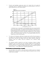
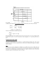
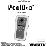
EUTECH INSTRUMENTS PTE LTD.
AMMONIA GAS-SENSING ELECTRODE
INSTRUCTION MANUAL
TABLE OF CONTENTS
TABLE OF CONTENTS .................................................................................................................................1
GENERAL INSTRUCTIONS .........................................................................................................................1
Introduction.................................................................................................................................................1
Required Equipment ...................................................................................................................................1
Required Solutions......................................................................................................................................1
GENERAL PREPARATION ..........................................................................................................................2
Electrode Preparation..................................................................................................................................2
Checking Membrane...................................................................................................................................2
Changing Membrane (see Figure 4) ...........................................................................................................2
Connecting the Electrode to the Meter .......................................................................................................3
Electrode Slope Check (with pH/mV meter) ..............................................................................................3
Electrode Slope Check (with ion meter).....................................................................................................3
MEASUREMENT ............................................................................................................................................4
Measuring Hints..........................................................................................................................................4
Sample Storage ...........................................................................................................................................4
Sample Requirements .................................................................................................................................4
Units of Measurement.................................................................................................................................5
MEASUREMENT PROCEDURE ..................................................................................................................5
Direct Measurement....................................................................................................................................5
Direct Measurement of Ammonia (using a pH/mV meter) ........................................................................5
Direct Measurement of Ammonia (using an ion meter) .............................................................................6
Low Level Ammonia Determination (using a pH/mV meter) ....................................................................7
Ammonia Measurements in Membrane Wetting Solutions ........................................................................8
ELECTRODE CHARACTERISTICS ...........................................................................................................9
Reproducibility ...........................................................................................................................................9
Interference .................................................................................................................................................9
Effect of Dissolved Species ........................................................................................................................9
Complexation............................................................................................................................................10
Temperature Influences ............................................................................................................................10
Electrode Response...................................................................................................................................10
Limits of Detection ...................................................................................................................................11
pH Effects .................................................................................................................................................11
Electrode Life ...........................................................................................................................................11
Electrode Storage......................................................................................................................................11
ELECTRODE THEORY...............................................................................................................................11
Electrode Operation ..................................................................................................................................11
Ammonia Chemistry.................................................................................................................................12
TROUBLESHOOTING GUIDE...................................................................................................................13
Meter.........................................................................................................................................................13
Glassware..................................................................................................................................................14
Electrodes .................................................................................................................................................14
Standards...................................................................................................................................................14
Sample ......................................................................................................................................................14
Technique .................................................................................................................................................15
TROUBLESHOOTING HINTS....................................................................................................................16
Checking the Electrode Inner Body..........................................................................................................18
SPECIFICATIONS ........................................................................................................................................19
ORDERING INFORMATION......................................................................................................................19
GENERAL INSTRUCTIONS
Introduction
Eutech Instruments Ammonia Gas-Sensing Electrode is used to quickly, simply, accurately, and
economically measure dissolved ammonia in aqueous solutions. It can also be used to measure the
ammonium ion after conversion to ammonia or organic nitrogen from Kjeldahl digestion of the
sample. The measurement is not affected by sample color or turbidity and samples do not need to be
distilled. Interference from anions, cations, and dissolved species, other than volatile amines, do not
occur. With a flow-through cap, the electrode can be used in flow-through applications.
Required Equipment
1.
A pH/mV meter or an ion meter, either line operated or portable.
2.
Semi-logarithmic 4-cycle graph paper for preparing calibration curves when using the
meter in the mV mode.
3.
A magnetic stirrer.
4.
Eutech Ammonia Gas-sensing Electrode, Code No. EC-NH3-01.
Required Solutions
1.
Deionized or distilled water for solution preparation.
2.
Eutech Ammonia Standard, 0.1M NH4Cl, Code No. EC-SCS-AA1-BT. To prepare this
solution from your own laboratory stock, half fill a one liter volumetric flask with distilled
water and add 5.35 grams of reagent-grade NH4Cl. Swirl the flask gently to dissolve the
solid. Fill the flask to the mark with distilled water, cap, and upend several times to mix
the solution.
3.
Eutech Ammonia Standard, 1,000 ppm NH3 as N, Code No. EC-SCS-AA2-BT. To prepare
this solution from your own laboratory stock, half fill a one liter volumetric flask with
distilled water and add 3.82 grams of reagent-grade NH4Cl. Swirl the flask gently to
dissolve the solid. Fill the flask to the mark with distilled water, cap, and upend several
times to mix the solution.
4.
Eutech Ammonia Standard, 100 ppm NH3 as N, Code No. EC-SCS-AA3-BT. To prepare
this solution from your own laboratory stock, half fill a one liter volumetric flask with
distilled water and add 0.382 grams of reagent-grade NH4Cl. Swirl the flask gently to
dissolve the solid. Fill the flask to the mark with distilled water, cap, and upend several
times to mix the solution.
5.
Eutech Ionic Strength Adjuster (ISA) Solution, 10 M NaOH, Code No. EC-ISA-AA1-BT.
To prepare this solution from your own laboratory stock, half fill a 1,000 ml beaker with
distilled water, add 400 grams of reagent-grade NaOH (sodium hydroxide). Swirl the flask
gently under a hood to dissolve the solid. Allow to cool and fill to the mark with distilled
water. Stir the solution and store in a plastic bottle.
6.
Eutech Ionic Strength Adjuster (ISA) Solution, 5M NaOH/.05M Disodium EDTA/10%
Methanol with Color Indicator, Code No. EC-ISA-AA2-BT. To prepare this solution from
your own laboratory stock, half fill a 1,000 ml beaker with distilled water and add 200
grams of reagent-grade NaOH. Stir the solution to dissolve the pellets, add 18.61 grams of
disodium EDTA, and stir the solution again until all solids have dissolved. Allow solution
to cool. In a separate 150 ml beaker, add a tiny amount (10-20 mg) of thymolphthalein to
100 ml of methanol and stir to dissolve. Pour the methanol solution into the 1,000 ml
beaker and stir to blend. The solution should turn a dark blue. Fill to the 1,000 ml mark
with distilled water and stir to blend.
GENERAL PREPARATION
Electrode Preparation
This electrode is shipped dry. Before using, unscrew the large cap (See Figure 5), and remove the
inner glass electrode from the outer body. Fill the outer body with 2 to 3 ml of internal filling
solution. Place the inner glass electrode into the outer body, and screw on the large cap until finger
tight. Place the assembled electrode in an electrode holder with a 20o angle from the vertical to
avoid trapping air bubbles at the bottom of the electrode.
Checking Membrane
A small hole of any size on the membrane or breakage of the membrane causes failure of the
electrode. It is recommended to check the membrane on every newly assembled electrode.
1.
Connect a newly assembled electrode to a pH/mV meter.
2.
Lower the electrode tip in distilled water.
3.
Record the reading after stirring the distilled water for about 15 minutes.
4.
Add proper ISA solution (see Required Solutions) to the distilled water. A drastic change
in the reading in a negative direction indicates damage of the membrane.
Changing Membrane (see Figure 4)
1.
Unscrew the top cap from the outer body and remove the inner glass body from the epoxy
outer body. Carefully place the glass body aside.
2.
Unscrew the bottom cap from the outer body. Remove the old membrane from around the
threads and electrode tip opening.
3.
Using the tweezers provided, grab a new piece of white membrane material by the edge
and remove from the separator paper. Then, with the hand not holding the tweezers, hold
the electrode body up at the threads with thumb and forefinger. Place one edge of the
membrane against the threads and hold in place with your thumb. Stretch new membrane
lengthwise across the electrode opening so that it smoothly covers the opening. Place the
other edge of the membrane against the threads and hold in place with your forefinger.
4.
Place the bottom cap gently over the membrane onto the threads and screw the bottom cap
on until finger-tight. Check that the membrane is free of wrinkles and holes or else repeat
the above steps.
5.
Using the syringe provided, fill the outer body with approximately 2 ml of inner filling
solution. Place glass inner body into epoxy outer body containing the internal filling
solution and screw on the upper cap until finger-tight.
Connecting the Electrode to the Meter
Connect the electrode to the meter according to meter manufacturer's instructions. No external
reference electrode is required. To prevent air entrapment, mount the electrode at a 20o angle from
the vertical.
Electrode Slope Check (with pH/mV meter)
(check electrodes each day)
1.
To a clean, dry, 150 ml beaker, add 100 ml of distilled water and 1 ml of ISA. Place the
beaker on a magnetic stirrer and begin stirring at a constant rate. After assuring that the
meter is in the millivolt mode, lower the electrode tip into the solution. Remove air bubbles
by redipping probe.
2.
Using a pipet, add 1 ml of 0.1M or 1,000 ppm standard into the solution. When the reading
has stabilized, record the mV value.
3.
Using a pipet, add 10 ml of the same ammonia standard used above to the beaker. When
the reading has stabilized, record the mV value.
4.
Determine the difference between the two readings. The electrode is operating correctly if
a difference of 56±3 mV is found, assuming the solution temperature is between 20o and
25oC. See the TROUBLESHOOTING section if the potential change is not within this range.
Slope is defined as the change in potential observed when the concentration changes by a factor of
10.
Electrode Slope Check (with ion meter)
(check electrodes each day)
1.
Prepare standard ammonia solutions whose concentrations vary by tenfold. Use either the
0.1M or 1,000 ppm ammonia standard. Use the serial dilution method for this preparation.
2.
To a 150 ml beaker, add 100 ml of the lower value standard and 1 ml of ISA. Place the
beaker on the magnetic stirrer and begin stirring at a constant rate. Lower the electrode tips
into the solution. Assure that the meter is in the concentration mode.
3.
Adjust the meter to the concentration of the standard and fix the value in the memory
according to the meter manufacturer's instructions.
4.
Rinse the electrodes with distilled water and blot dry.
5.
To another 150 ml beaker, add 100 ml of the higher value standard and 2 ml of ISA. Place
the beaker on the magnetic stirrer and begin stirring at a constant rate. Lower the electrode
tips into the solution.
6.
Adjust the meter to the concentration of the standard and fix the value in the memory.
7.
Read the electrode slope according to the meter manufacturer's instructions. Correct
electrode operation is indicated by a slope of 90-100%. See TROUBLESHOOTING section if
the slope is not within this range.
MEASUREMENT
Measuring Hints
Samples should be measured immediately after collection. Samples should be stored according to
the directions given in Sample Storage if immediate measurement is not possible.
The ratio of a surface area to volume in the beaker should be minimized. Beakers containing the
samples or the standard should be kept covered between measurements.
The ammonia ISA, 10M NaOH, should be added just before measurement. All samples and
standards should be at the same temperature for precise measurement. A difference of 1oC in
temperature will result in approximately a 2% error. All samples must be aqueous.
Always rinse the electrode with distilled water and blot dry between measurements. Use a clean,
dry tissue to prevent cross-contamination.
Constant, but not violent, stirring is necessary for accurate measurement. Magnetic stirrers can
generate sufficient heat to change solution temperature. To counteract this effect, place a piece of
insulating material, such as gauze or styrofoam, between the beaker and the magnetic stirrer.
Always check to see that the membrane is free from air bubbles after immersion into standard or
sample.
Sample Storage
Samples should be measured immediately after preparation or collection, if possible. Wait only long
enough for temperature equilibration between the sample and the electrode. If stirring a 100 ml
basic solution in a 150 ml beaker, the rate of ammonia loss at room temperature is about 50% in six
hours. The loss of C02 increases with increasing temperature.
If the samples cannot be measured immediately, add 0.5 ml of 1M HCl to each liter of sample to
make them slightly acidic (pH 6) and store in tightly capped vessels. Prior to measurement, add
10M NaOH to make the samples slightly basic.
Sample Requirements
Sodium hydroxide buffer must be added to standards and samples before measurement. When 10M
NaOH is added, all standards and samples should be in the range of pH 11 to 14. In this range, all
ammonium species are converted to ammonia. Adding the 10M NaOH adjusts the total level of
dissolved species below 1M. If the total level is greater than 1M, the sample should be diluted
before measurement. For further explanation, see the section entitled Effect of Dissolved Species.
Units of Measurement
Measurement of ammonia can be expressed in units of moles/liter, ppm as nitrogen, ppm as
ammonia, or other convenient concentration unit. Table 1 lists conversion units.
TABLE 1: Concentration Unit Conversion Factors
moles/liter
10-2
10-3
10-4
ppm N
ppm NH3
140.0
14.0
1.4
170.0
17.0
1.7
MEASUREMENT PROCEDURE
Direct Measurement
Direct measurement is a simple procedure for measuring a large number of samples. A single meter
reading is all that is required for each sample. The ionic strength of samples and standards should
be made the same by adjustment with ISA for all ammonia solutions. The temperature of both
sample solutions and standard solutions should be the same.
Direct Measurement of Ammonia (using a pH/mV meter)
1.
By serial dilution, prepare three standard solutions from the 0.1M or 1,000 ppm stock
standard. The resultant concentrations should be 10-2M, 10-3M, and 10-4M or 1,000, 100
and 10 ppm ammonia standards. Add 1 ml of ISA per 100 ml of standard. Prepare
standards with a composition similar to the samples if the samples have an ionic strength
above 0.1M.
2.
Place the most dilute solution (10-4M or 10 ppm) on the magnetic stirrer and begin stirring
at a constant rate. After assuring that the meter is in the mV mode, lower the electrode tip
into the solution. After the reading has stabilized, record the mV value.
3.
Place the mid-range solution (10-3M or 100 ppm) on the magnetic stirrer and begin stirring
at a constant rate. After rinsing the electrode with distilled water, blot dry, and immerse the
electrode tip in the solution. When the reading has stabilized, record the mV value.
4.
Place the most concentrated solution (10-2M or 1,000 ppm) on the magnetic stirrer and
begin stirring at a constant rate. After rinsing the electrode with distilled water, blot dry,
and immerse the electrode tip in the solution. When the reading has stabilized, record the
mV value.
5.
Using the semi-logarithmic graph paper, plot the mV reading (linear axis) against the
concentration (log axis). Extrapolate the calibration curve down to about 1.0 x 10⁻⁵M. A
typical calibration curve can be found in Figure 1.
A calibration curve is constructed on semi-logarithmic paper when using the pH/mV
meter in the millivolt mode. The measured electrode potential in mV (linear axis) is
plotted against the standard concentration (log axis). In the linear region of the curve,
only three standards are necessary to determine a calibration curve. In the non-linear
region, additional points must be measured. The direct measurement procedures
given are for the linear portion of the curve. The non-linear portion of the curve
requires the use of low level procedures.
6.
To a clean, dry 150 ml beaker, add 100 ml of sample and 1 ml of ISA. Place the beaker on
the magnetic stirrer and begin stirring at a constant rate. Rinse the electrodes with distilled
water, blot dry, and lower the electrode tip into the solution. When the reading has
stabilized, record mV reading. Using the calibration curve, determine sample
concentration.
7.
The calibration should be checked every two hours. Assuming no change in ambient
temperature, place the electrode tips in the mid-range standard. After the reading has
stabilized, compare it to the original reading recorded in Step 3 above. A reading differing
by more than 0.5 mV or a change in the ambient temperature will necessitate the repetition
of steps 2-5 above. A new calibration curve should be prepared daily.
Direct Measurement of Ammonia (using an ion meter)
1.
By serial dilution of the 0.1M or 1,000 ppm ammonia standard, prepare two ammonia
standards whose concentration is near the expected sample concentration. Add 1 ml of ISA
to each 100 ml of standard.
2.
3.
Place the more dilute solution on the magnetic stirrer and begin stirring at a constant rate.
Assure that the meter is in the concentration mode.
Lower the electrode tip into the solution.
4.
Adjust the meter to the concentration of the ammonia standard and fix the value in the
memory according to the meter manufacturer's instructions after stabilization of the
reading.
5.
Rinse the electrode with distilled water and blot dry.
6.
Place the most concentrated solution on the magnetic stirrer and begin stirring at a constant
rate.
7.
Lower the electrode tip into the solution. Adjust the meter to the concentration of the
ammonia standard and fix the value in the memory according to the meter manufacturer's
instructions after stabilization of the reading.
8.
For low level measurements, place the rinsed, dried electrodes into a solution containing
100 ml of distilled water and 1 ml of ISA. After stabilization, fix the blank value in the
meter according to the meter manufacturer's instructions.
9.
Place 100 ml of the sample and 1 ml of ISA in a 150 ml beaker. Place the beaker on the
magnetic stirrer and begin stirring.
10.
Lower the electrode tip in solution. When the reading has stabilized, read the concentration
directly from the meter display.
11.
The calibration should be checked every 2 hours. Assuming no change in ambient
temperature, place the electrode tip in the first ammonia standard. After the reading has
stabilized, compare it to the original reading in step 3 above. A reading differing by more
than 0.5 units or a change in ambient temperature will necessitate the repetition of steps 28 above. The meter should be re-calibrated daily.
Low Level Ammonia Determination (using a pH/mV meter)
As the concentration of ammonia decreases, the rate of ammonia diffusion through the membrane is
slow, the rate of equilibrium between the ammonium in the internal filling solution and ammonia is
slow, and thus the response time increases. If the internal filling solution is diluted with ammoniafree distilled water (1:10), response at low levels can improve. Measurements can be speeded up by
first placing the electrode tip in an ammonia-free pH 4 buffer, then into the sample. Always keep
standards and samples covered. Work with large solution volumes to minimize surface-area-tovolume ratio, thereby avoiding ammonia absorption from air. Allow 5-10 minutes for a stable
reading in the pH 4 buffer or a low-level solution.
Use the following low level ammonia measurement procedure in the non-linear portion of the
calibration curve. (See Figure 1.) This procedure is used for ammonia samples containing less than
1.0x10⁻⁵M ammonia.
1.
Measure out 100 ml of a pH 4 buffer solution, add it to a 150 ml beaker, place the beaker
on the magnetic stirrer, and begin stirring. Place the electrode tip in the solution for about 3
minutes.
2.
By serial dilution, prepare a 10-2M or 100 ppm ammonia standard by diluting the 0.1M or
1,000 ppm standard solution.
3.
To a 2500 ml erlenmeyer flask, add 1,000 ml of distilled water and 10 ml of 10M NaOH.
Place on magnetic stirrer and begin stirring. After rinsing the electrode, place the tip in this
calibration solution. Assure that the meter is in the mV mode.
4.
Using a 1 ml graduated pipet (A) and a 2 ml pipet (B), add increments of the 10-2M or 100
ppm dilution to the calibration solution using the steps outlined in Table 2. Allow the
reading to reach equilibrium and record the electrode potential after each step. Plot the
concentration (log axis) vs. the electrode potential (linear axis) on semi-logarithmic paper
to obtain the calibration curve.
5.
After rinsing the electrode, immerse the electrode tip in pH 4 buffer for 3 minutes. Be sure
to use the magnetic stirrer.
6.
Place 1,000 ml of the sample into a 1,000 ml beaker, add 10 ml of 10M NaOH, place the
beaker on the magnetic stirrer, and begin stirring. After rinsing the electrodes, immerse the
tip in the solution. When the reading has stabilized, record the mV potential.
7.
Determine concentration from the calibration curve. (Prepare a new low-level calibration
curve on a daily basis using freshly prepared solutions).
TABLE 2:
Additions of 10-2M or 100 ppm Standard to 1,000 ml Distilled Water
and 10 ml 10M NaOH
Step
1
2
3
4
5
6
7
Pipet
A
A
A
A
A
B
B
Added
Volume(ml)
0.10
0.10
0.20
0.20
0.40
2.00
2.00
Concentration
M
ppm
0.01
9.9 x 10⁻⁷
0.02
2.0 x 10⁻⁶
6
0.04
4.0 x 10
0.06
5.9 x 10⁻⁶
0.10
9.9 x 10⁻⁶
5
0.30
3.0 x 10
0.49
4.9 x 10⁻⁵
Ammonia Measurements in Membrane Wetting Solutions
Since the membrane of the ammonia electrode is gas-permeable and hydrophobic, liquid water does
not penetrate the membrane holes and does not wet it. A non-aqueous solution, or a solution
containing a surfactant which wets the membrane, penetrates the membrane. Non-aqueous samples,
such as latex paints or nylon, and those containing surfactants, such as sewage, cause measurement
difficulties. The electrode must be suspended above the sample to measure ammonia in such
samples.
Since water vapor reacts with ammonia in the gas phase, placing the ammonia electrode in a closed
system containing water vapor will allow measurements of solutions above 10-3M (14 ppm) to be
taken.
Ammonia in samples containing non-aqueous solutions or surfactants can be measured by adjusting
the sample pH to 11 to 13 with 10M NaOH. After measuring the sample, transfer it to an
erlenmeyer flask large enough to contain approximately 2/3 volume of air after sample addition.
Place a magnetic stir bar in the flask, fit the flask with a one-hole rubber stopper (opening large
enough to insert the electrode snugly), and insert the electrode until it is just above the level of
liquid in the flask. The closed flask now forms an air-tight closed system with the gas phase
saturated with water vapor. The partial pressure of ammonia is in equilibrium with the solution.
For gas phase measurements, calibrate the electrode in a closed flask using standards. The response
time for the ammonia electrode will be longer in the gas phase than if it were actually immersed in a
surfactant-free, aqueous solution.
ELECTRODE CHARACTERISTICS
Reproducibility
Electrode measurements reproducible to ±2% can be obtained if the electrode is calibrated every
hour. Factors such as temperature fluctuation, drift, and noise limit reproducibility. Reproducibility
is independent of concentration within the operating range of the electrode.
Interference
Volatile amines interfere with the operation of the ammonia electrode. Most gases, since they are
converted to the ionic form in basic solutions, do not interfere with ammonia electrode
measurement. The level of ions in solution can change the solubility of ammonia, though ionic
species cannot cross the gas-permeable membrane and are not considered direct electrode
interference. The level of ions in sample solution and standards do not interfere, given that they are
equal. The same holds true for dissolved species. Low results can occur in direct measurements, due
to the presence of some metallic ions and their complexation effect on ammonia.
Effect of Dissolved Species
One common substance that is a potential electrode interference is water vapor. The concentration
of the internal filling solution under the membrane is changed when water, in the form of water
vapor, moves across the electrode membrane. These changes will be seen as electrode drift. If the
total level of dissolved species in solution, the osmotic strength, is below 1M and the sample and
electrode temperatures are the same, water vapor transport is not a problem.
Samples of low osmotic strength are automatically adjusted to the correct level through addition of
10M NaOH. If samples have osmotic strengths greater than 1M, they should be diluted before
measurement. However, this dilution should not reduce the ammonia level below 10-5M. If dilution
is not possible, for the reason mentioned, the sample can be measured by adjusting the osmotic
strength of the electrode filling solution. The total level of dissolved species in the electrode filling
solution may be adjusted by adding 0.425 grams of reagent-grade sodium nitrate (NaNO3) to 10 ml
of the electrode filling solution.
Complexation
Metal complexes are formed with ammonia and a number of metal ions. Complexes of mercury,
copper, gold, silver, nickel, zinc, cobalt, and cadmium are removed in the form of hydroxide
complexes or precipitates in basic solution. When ammonia concentration is below 10-3M and
hydroxide is present at the 10-1M level, the only appreciable complex formed will be between
mercury and ammonia. Since the total ammonia level of a sample will be measured if the mercury is
preferentially bound to another species, addition of iodide is recommended for this purpose. Use of
the recommended ISA (10M NaOH solution) inhibits the formation of metal complexes in the
sample, since it contains a high concentration of hydroxide ions.
Temperature Influences
Table 4 gives the variation of theoretical response with temperature. The electrode response will
shift and change slope with change in temperature. Standards and samples should be at the same
temperature. A 2% error results with a 1oC temperature change for a 10-3M solution. Gases are
expelled from a solution at a faster rate as the temperature increases.
TABLE 4: Temperature vs. Values for Electrode Slope
Temp.(oC)
0
5
10
15
20
25
30
35
40
"S"
54.20
55.20
56.18
57.17
58.16
59.16
60.15
61.14
62.13
Electrode Response
Plotting the electrode mV potential against the ammonia concentration on semi-logarithmic paper
results in a straight line with a slope of about 56 mV per decade. (See Figure 1.)
For ammonia concentrations above 4X10⁻⁶M (0.07 ppm NH3 or 0.06 ppm N), the electrode exhibits
good time response (95% of total mV reading in one minute or less). Response times are longer
below this value and ammonia loss to air may become a source of error. Figure 2 indicates the time
response of ammonia electrode to changes in the ammonia concentration.
Limits of Detection
The upper limit of detection in pure ammonia solutions is 1M. Ammonia is rapidly lost to the air
above a concentration of 1M. Dilution may be used if ammonia concentrations are above 1M. Also
dilute samples between 1M and 10-1M or calibrate the electrode at 4 or 5 intermediate points.
The lower limit of detection is around 1X10⁻⁶ M. Refer to Figure 1 for a comparison of the
theoretical response to the actual response at low levels of ammonia. Ammonia measurements
below 10-5M NH3 should employ low level procedures.
pH Effects
The ammonia electrode can be used over the pH range 11 to 14. It is necessary to adjust the sample
pH to above 11 using the recommended ISA to convert all ammonium species in solution to
ammonia.
Electrode Life
The ammonia ion electrode will last six months in normal laboratory use. On-line measurements
might shorten operational lifetime to several months. In time, the response time will increase and
the calibration slope will decrease to the point calibration is difficult and membrane replacement is
required.
Electrode Storage
If erratic results are obtained from accidentally leaving the electrode in air, the space between the
sensing element and the inside of the membrane may be dry. To remedy this situation and allow
new filling solution to flow into the space, withdraw the glass electrode from the membrane by
pulling the cable slightly.
For low level measurements, immerse the tip of the electrode in pH 4 buffer between
measurements. For normal range measurements, keep the electrode tip immersed in a 0.001M or 10
ppm standard with added NaOH between measurements.
If storing the ammonia electrode overnight or over the weekend, immerse the tip in the 0.1M
standard without added NaOH. Do not store overnight in pH 4 buffer.
For longer periods of time, completely disassemble the electrode, rinse the inner body, the outer
body, and the cap with distilled water. After drying, reassemble the electrode without filling
solution.
ELECTRODE THEORY
Electrode Operation
A gas-permeable membrane is used to separate the electrode's internal solution from the sample
solution in the Eutech Ammonia Gas-Sensing Electrode. The sample diffuses dissolved ammonia
through the membrane until the partial pressure of ammonia is the same on both sides of the
membrane. The partial pressure of ammonia is proportional to the ammonia concentration.
The ammonia that diffuses through the membrane dissolves in the internal filling solution, reacting
reversibly with water in the filling solution, to a small extent:
NH3 + H2O ⇒ NH4+ + OHThe equilibrium equation gives rise to the equilibrium constant in the following equation:
[NH4+] [OH-]
constant = ⎯⎯⎯⎯⎯⎯⎯
[NH3]
The ammonium ion concentration can be considered fixed, since the internal filling solution
contains ammonium chloride at a sufficiently high level. As a result:
[OH-] = [NH3] x constant
The electrode sensing element's potential, with respect to the internal reference element, varies in a
Nernstian manner with changes in the hydroxide level:
E = Eo - S log [OH-]
where S is the slope of the electrode.
Because the hydroxide concentration is proportional to the ammonia concentration, electrode
response to ammonia is also Nernstian:
E = Eo1 - S log [NH3]
Eo1 represents the reference potential and is partly determined by the internal reference element
which responds to the fixed level of chloride in the internal filling solution.
Ammonia Chemistry
As mentioned earlier, ammonia dissolves in water to form the ammonium ion. Ammonia also
reacts with hydrogen (hydronium) ions to form ammonium ions:
NH3 + H3O+ ⇒ NH4+ + H2O
The relative amounts of the ammonium ion and of ammonia is determined by the solution's pH.
Virtually, all the ammonia is converted to ammonium ion where hydrogen ion is readily available,
as in acid solution. Half the ammonia will be in the form of ammonium ion at a pH of about 9.3.
(See Figure 3).
It is possible to calculate the ratio of ammonia to ammonium ion, theoretically, if the pH is known.
A. Martell and R. Smith in Critical Stability Constants, Plenum Press, New York, 1974, state:
[NH4+]
[NH4+]
⎯⎯⎯⎯ = ⎯⎯⎯⎯ K ~ 10-9.3
[NH3]
10-pH [NH3]
[H3O+]
at 25oC, X = 0.1 where pH ~ 9.3
The ratio of ammonium to ammonia is given by:
[NH4+]
⎯⎯⎯⎯ = K-pH = 10 9.3-pH
[NH3]
Both temperature and ionic strength will cause the exact value of K to vary. If, for example, while
the pH at 25oC and X = 0.1 is 9.3, an increase in ionic strength to X = 1.0 yields a pH of 9.4, at
25oC.
TROUBLESHOOTING GUIDE
The goal of troubleshooting is the isolation of a problem through checking each of the system
components in turn: the meter, the glassware the electrodes, the standard and reagents, the sample,
and the technique.
Meter
The meter is the easiest component to eliminate as a possible cause of error. Most meters are
provided with an instrument check-out procedure in the instruction manual and a shorting strap for
convenience in troubleshooting. Consult the manual for complete instructions and verify that the
instrument operates as indicated and is stable in all steps.
Glassware
Clean glassware is essential for good measurement. Be sure to wash the glassware well with a mild
detergent and rinse very well with distilled or deionized water. Clean glassware will drain without
leaving water droplets behind.
Electrodes
The electrodes may be checked by using the procedure found in the section entitled Electrode
Slope Check.
1.
Be sure to use either distilled or deionized water when following the procedures given in
Electrode Slope Check.
2.
If electrode fails to response as expected, see the sections entitled Electrode Assembly and
Checking Membrane. Repeat electrode slope check.
3.
If the electrode still does not perform as described, determine whether the ammonia
electrode inner body is working properly as directed in Checking the Electrode Inner
Body.
4.
If the stability and the slope check out properly, but measurement problems persist, the
standards may be of poor quality, the sample may contain interference or complexing
agents, or the technique may be in error. (See Standard, Sample and Technique sections
below.)
5.
Before replacing a "faulty" electrode, review the instruction manual and be sure to:
- Clean and rinse the electrode thoroughly.
- Prepare the electrode properly.
- Use proper filling solution, buffer, and standards.
- Measure correctly and accurately.
- Review TROUBLESHOOTING HINTS.
Standards
The quality of results depends greatly upon the quality of the standards. ALWAYS prepare fresh
standards when problems arise. It could save hours of frustrating troubleshooting! Error may result
from contamination of prepared standards, accuracy of dilution, quality of distilled water, or a
mathematical error in calculating the concentrations.
The best method for preparation of standards is by serial dilution. This means that an initial
standard is diluted, using volumetric glassware, to prepare a second standard solution. The second
is similarly diluted to prepare a third standard, and so on, until the desired range of standards has
been prepared.
Sample
If the electrode works properly in standards but not in sample, look for possible interference,
complexing agents, or substances which could affect response or physically damage the sensing
electrode or the reference electrode. If possible, determine the composition of the samples and
check for problems. See Sample Requirements and Interference.
Technique
Be sure that the electrode's limit of detection has not been exceeded. Be sure that the analysis
method is clearly understood and is compatible with the sample. Refer to the instruction manual
again. Reread the sections GENERAL PREPARATION and ELECTRODE CHARACTERISTICS.
If trouble still persists, call Eutech Instruments Pte Ltd. at (65) 6778-6876 and ask for the Customer
Services Department.
TROUBLESHOOTING HINTS
Symptom
Out of Range
Reading
Possible Causes
defective meter
Next Step
perform meter checkout procedure
(see meter instruction manual)
defective inner body
refer to Checking the Electrode
Inner Body
electrode not
plugged in properly
unplug electrode and reset
internal filling
solution not added
fill outer body of electrode with proper
amount of internal filling solution
air bubble on membrane
remove bubble by re-dipping
electrode
electrode not in solution
Noisy or Unstable
insufficient
Reading (readings
internal filling solution
continuously or
randomly changing.) defective meter
put electrode in solution
fill outer body of electrode with proper
amount of internal filling solution
perform meter checkout procedure
(see meter instruction manual)
bottom cap loose
ensure that bottom cap is screwed on
tight enough to close gap between
bottom cap and body
defective inner body
refer to Checking the Electrode
Inner Body
air bubbles on membrane
remove bubbles by redipping electrode
meter or stirrer
improperly grounded
check meter and stirrer for
grounding
Drift (reading slowly internal filling
changing in one
solution leakage
ensure that membrane is installed
properly
incorrect internal
filling solution
refill outer body of electrode using
filling solution shipped with electrode
total sample level
dilute sample of dissolved species
above 1M
electrode in sample
too long; NH3 loss
reduce surface area to volume ratio,
slow down rate of stirring, avoid
high temperatures
membrane failure
(wet, perforation,
discoloration)
replace membrane
samples and standards
standards not at
constant temperature
allow samples and standards to come
to room temperature before use
heat generated by
magnetic stirrer
place insulating material between
stirrer and beaker
defective inner body
refer to Checking the Electrode
Inner Body
Low Slope or
No Slope
electrode exposed
to air for extended period
hold electrode by outer body and
pull on electrode cable. Internal
filling solution will flow under
membrane and restore electrode
response
standards contaminated
or incorrectly made
prepare fresh standards
buffer not used
use recommended buffer
standard used as buffer
use buffer
electrode exposed
to air for extended period
hold electrode by outer body and
pull on electrode cable. internal
filling solution will flow under
membrane and restore electrode
response
membrane failure
(wet, perforation,
discoloration)
replace membrane
defective inner body
refer to Checking the Electrode
Inner Body
"Incorrect Answer"
(but calibration
curve is good)
incorrect scaling
of semi-log paper
plot millivolts on the linear axis. On
the log axis, be sure concentration
numbers within each decade are
increasing with increasing
concentration
incorrect sign
be sure to note sign of millivolt
value correctly
incorrect standards
prepare fresh standards
wrong units used
apply correct conversion factor:
10-3M = 17 ppm as
NH3 = 14 ppm as N
buffer added to
standards and not
samples
add same proportions of buffer to
standards and samples
sample carryover
rinse electrodes thoroughly
between samples
Checking the Electrode Inner Body
If the electrode slope is found to be low during operation, the following solutions will be necessary
to check the inner body:
- pH 4 Buffer (0.1M NaCl added)
Add 2.9 grams of reagent-grade NaCl to 500 ml of pH 4 buffer. Dissolve the solid. The solution
may be stored for repeated use.
- pH 7 Buffer (0.1M NaCl added)
Add 2.9 grams of reagent-grade NaCl to 500 ml of pH 7 buffer. Dissolve the solid. The solution
may be stored for repeated use.
Disassemble the ammonia electrode. If the electrode is dry, soak the glass tip of the inner body in
Eutech Ammonia Electrode Filling Solution (Code No. EC-RE-032) for at least two hours.
Rinse the electrode thoroughly with distilled water. Put 100 ml of pH 7 buffer (0.1M NaCl added)
in a 150 ml beaker. Place the beaker on the magnetic stirrer, and begin stirring. Immerse the tip of
the inner body in the solution so that the reference element is covered. Make sure that the meter is
in the mV mode. Record the meter reading when stable.
Rinse the inner body thoroughly in distilled water. Put 100 ml of pH 4 buffer (0.1M NaCl added) in
a 150 ml beaker, place the beaker on the magnetic stirrer, and begin stirring. Immerse the tip of the
inner body in the solution so that the reference element is covered. Observe the change in the meter
reading carefully. In less than 30 seconds after immersion, the reading should change 100 mV. The
meter reading should stabilize in 3 - 4 minutes, with a difference greater than 150 mV if the inner
body sensing elements are operating properly.
SPECIFICATIONS
Concentration Range:
5 x 10⁻⁷M to 1 M NH3
(0.01 to 17,000 ppm NH3)
(0.01 to 14,000 ppm as N)
pH Range:
above 11
Temperature Range:
0o to 50oC
Inner Body Resistance:
~1,000 Mohm
Reproducibility:
+ 2%
Size:
110 mm length; 12 mm diameter; 1 m cable length
Storage:
Store electrodes in 0.1M NH4Cl
ORDERING INFORMATION
CODE NO.
DESCRIPTION
EC-NH3-01
Ammonia Gas Sensing Electrode
EC-MIS-AM
Ammonia Membrane Kit, bag of 20 membranes and spare o-ring
EC-SCS-AA1-BT Ammonia Standard, 0.1M NH4Cl
EC-SCS-AA2-BT Nitrogen Standard, 1,000 ppm NH3 as N
EC-SCS-AA3-BT Nitrogen Standard, 100 ppm NH3 as N
EC-ISA-AA1-BT
Ammonia Ionic Strength Adjuster (ISA) Solution, 10 M NaOH
EC-ISA-AA2-BT
Ammonia Ionic Strength Adjuster (ISA) Solution,
5M NaOH/.05M Disodium EDTA/10% Methanol with Color Indicator.