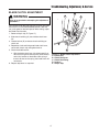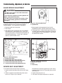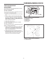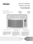
1
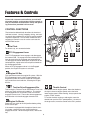
.-4415
OPERATOR’S
MANUAL
Field and Brush Mower
9HP/13HP Hydro Mowers
Mfg. No.
1694240
1694249
1694254
1694378
Description
9HP/13HP Walk-Behind Brush Mower (Simplicity)
9HP/13HP Walk-Behind Brush Mower (Ferris GM2509BS, GM2513BS)
9HP/13HP Walk-Behind Brush Mower (Giant-Vac GM2509BS, GM2513BS)
13HP Walk-Behind Brush Mower (Snapper FB13250BV)
13.5HP Hydro Mowers
Mfg. No.
1694204
1694251
1694253
Description
13.5HP Walk-Behind Brush Mower (Simplicity)
13.5HP Walk-Behind Brush Mower (Ferris GM2513H)
13.5HP Walk-Behind Brush Mower (Giant-Vac GM2513H)
15HP Hydro Mowers
Mfg. No.
1694205
1694250
1694252
1694379
Description
15HP Walk-Behind Brush Mower (Simplicity)
15HP Walk-Behind Brush Mower (Ferris GM2515AWV)
15HP Walk-Behind Brush Mower (Giant-Vac GM2515AWV)
15HP Walk-Behind Brush Mower (Snapper FB15250KW)
16HP Hydro Mowers
Mfg. No.
N/A
Description
16HP Walk-Behind Brush Mower (Giant-Vac GM2516BS-E)
1723519-02
Rev 1/2003
TP 100-2568-02-BC-UV
Table of Contents
Identification Numbers........................................1
Safety Rules & Information.................................2
Safety Decals .......................................................4
Features & Controls ............................................6
Troubleshooting, Adjustment and Service .....14
Chart .....................................................................14
Travel Control Adjustment ....................................16
Blade Clutch Adjustment.......................................17
Blade Brake Adjustment .......................................18
Mower Belt Adjustment .........................................18
Traction Drive Belt Adjustment .............................19
Mower Belt Replacement ......................................20
Control Functions ....................................................6
Operating the Mower...........................................7
Starting the Engine .................................................7
Engaging the Transmission ....................................7
Engaging/Disengaging the Cutting Blade ...............9
To Adjust Cutting Height .......................................10
Storage .................................................................10
Specifications ....................................................21
Parts & Accessories..........................................21
Replacement Parts ...............................................21
Maintenance Items................................................21
Technical Manuals ................................................21
Regular Maintenance ........................................11
Lubrication ............................................................11
Tire Pressure ........................................................12
Battery Service......................................................12
Servicing the Mower Blades .................................13
NOTE: In this manual, “left” and “right” are referred to as
seen from the operating position.
Identification Numbers
PRODUCT
REFERENCE
DATA
Model Description Name/Number
When contacting your authorized dealer for replacement parts, service, or information you MUST have
these numbers.
Record your model name/number, manufacturer's identification numbers, and engine serial numbers in the
space provided for easy access. These numbers can be
found in the locations shown (Figure 1).
Unit MFG Number
Unit SERIAL Number
Mower Deck MFG Number
Mower Deck SERIAL Number
Dealer Name
Date Purchased
NOTE: For location of engine identification numbers,
refer to the engine owner's manual.
ENGINE REFERENCE DATA
Engine Make
Engine Model
Engine Type/Spec
Engine Code/Serial Number
Model
Serial
Figure 1 - Serial Number Tag
1
Safety Rules & Information
Read these safety rules and follow them closely. Failure to obey these rules could result in loss of control of
unit, severe personal injury or death to you, or bystanders, or damage to property or equipment. This
mowing deck is capable of amputating hands and feet and throwing objects. The triangle in text signifies important cautions or warnings which must be followed.
SAFE OPERATION PRACTICES FOR
WALK-BEHIND MOWERS
This cutting machine is capable of amputating hands and
feet and throwing objects. Failure to observe the following safety instructions could result in serious injury or
death.
GENERAL OPERATION
• Read, understand, and follow all instructions on the
machine and in the manual(s). Be thoroughly familiar
with the controls and the proper use of the mower
before starting.
• Stop the blade(s) when crossing gravel drives, walks,
or roads.
• Shut off the engine (motor) whenever you leave the
equipment, before cleaning the mower or unclogging
the chute.
• Do not put hand or feet near or under rotating parts.
Keep clear of the discharge opening at all times.
• Shut the engine (motor) off and wait until the blade
comes to a complete stop before removing grass
catcher.
• Only allow responsible individuals, who are familiar
with the instructions, to operate the mower.
• Clear the area of objects such as rocks, toys, wire,
bones, sticks etc., which could be picked up and
thrown by the blade.
• Mow only in daylight or good artificial light.
• Do not operate the mower while under the influence
of alcohol or drugs.
• Be sure the area is clear of other people before mowing. Stop mower if anyone enters the area.
• Never operate mower in wet grass. Always be sure
of your footing; keep a firm hold on the handle and
walk; never run.
• Do not operate the mower when barefoot or wearing
open sandals. Always wear substantial foot wear.
• Disengage the self-propelled mechanism or drive
clutch on mowers so equipped before starting the
engine (motor).
• Do not pull mower backwards unless absolutely necessary. Look down and behind before and while
moving backwards.
• Do not operate the mower without proper guards,
plates, grass catcher or other safety protective
devices in place.
• If the equipment should start to vibrate abnormally,
stop the engine (motor) and check immediately for
the cause. Vibration is generally a warning of trouble.
• See manufacturer’s instructions for proper operation
and installation of accessories. Use only accessories
approved by the manufacturer.
• Always wear safety goggles or safety glasses with
side shields when operating mower.
2
Safety Rules and Information
SLOPE OPERATION
SERVICE
• Use extra care when handling gasoline and other
fuels. They are flammable and vapors are explosive.
WARNING
Never operate on slopes greater than 17.6 percent
(10°) which is a rise of 3-1/2 feet (106 cm) vertically in
20 feet (607 cm) horizontally.
Select slow ground speed before driving onto slope.
In addition to front and rear weights, use extra caution
when operating on slopes with rear-mounted grass
catcher.
Mow UP and DOWN the slope, never across the
face, use caution when changing directions and DO
NOT START OR STOP ON SLOPE.
a) Use only an approved container.
b) Never remove fuel cap or add fuel with the engine
running. Allow engine to cool before refueling. Do
not smoke.
c) Never refuel the machine indoors.
d) Never store the machine or fuel container inside
where there is an open flame, such as a water
heater.
• Never run an engine inside a closed area.
Slopes are a major factor related to slip and fall accidents, which can result in severe injury. All slopes
require extra caution. If you feel uneasy on a slope, do
not mow it.
• Never make adjustments or repairs with the engine
(motor) running. Disconnect the spark plug wire, and
keep the wire away from the plug to prevent accidental starting.
Do
• Remove obstacles such as rocks, tree limbs, etc.
• Keep all nuts and bolts, especially blade attachment
bolts, tight and keep equipment in good condition.
• Watch for holes, ruts, or bumps. Tall grass can hide
obstacles.
• Never tamper with safety devices. Check their proper operation regularly.
• Keep mower free of grass, leaves, or other debris
build-up. Clean up oil or fuel spillage. Allow mower
to cool before storing.
Do Not
• Do not mow near drop-offs, ditches, or embankments. The operator could lose footing or balance.
• Stop and inspect the equipment if you strike an
object. Repair, if necessary, before restarting.
• Do not mow excessively steep slopes.
• Never attempt to make wheel height adjustments
while the engine (motor) is running.
• Do not mow on wet grass. Reduced footing could
cause slipping.
• Always disconnect electric mowers (live operated)
before cleaning, repairing, or adjusting.
• Do not mow across the face of slopes; never up and
down. Do not change direction on slopes.
• Grass catcher components are subject to wear, damage, and deterioration, which could expose moving
parts or allow objects to be thrown. Frequently check
components and replace with manufacturer’s recommended parts, when necessary.
CHILDREN
Tragic accidents can occur if the operator is not alert to
the presence of children. Children are often attracted to
the unit and the mowing activity. Never assume that children will remain where you last saw them.
• Mower blades are sharp and can cut. Wrap the
blade(s) or wear gloves, and use extra caution when
servicing them.
• Keep children out of the mowing area and under the
watchful care of another responsible adult.
• Do not change the engine governor setting or overspeed the engine.
• Be alert and turn mower off if children enter the area.
* Asterisked items do not apply to electric mowers.
• Before and while moving backwards, look behind and
down for small children.
EMISSIONS
• Engine exhaust from this product contains chemicals
known, in certain quantities, to cause cancer, birth
defects, or other reproductive harm.
• Look for the relevant Emissions Durability Period and
Air Index information on the engine emissions label.
• Never allow children to operate the mower.
• Use extra care when approaching blind corners,
shrubs, trees, or other objects that may obscure
vision.
3
Safety Rules & Information
SERVICE AND MAINTENANCE
• Never make adjustments or repairs with the engine
running unless specified otherwise in the engine manufacturer's manual.
• Do not remove the fuel filter when the engine is hot
as spilled gasoline may ignite. Do not spread fuel line
clamps further than necessary. Ensure clamps grip
hoses firmly over the filter after installation.
• Do not use gasoline containing METHANOL, gasohol
containing more than 10% ETHANOL, gasoline additives, or white gas because engine/fuel system damage could result.
• Mower blades are sharp and can cut. Wrap the
blade(s) or wear gloves, and use extra caution when
servicing them.
• Check blade brake operation frequently. Adjust and
service as required.
• Use only factory authorized replacement parts when
making repairs.
• Always comply with factory specifications on all settings and adjustments.
• Only authorized service locations should be utilized
for major service and repair requirements.
• Never attempt to make major repairs on this unit
unless you have been properly trained. Improper service procedures can result in hazardous operation,
equipment damage and voiding of manufacturer's
warranty.
• Do not change engine governor settings or overspeed the engine. Operating the engine at excessive
speed can increase the hazard of personal injury.
• Disengage drive attachments, stop the engine,
remove the key, and disconnect the spark plug wire(s)
before: clearing attachment blockages and chutes,
performing service work, striking an object, or if the
unit vibrates abnormally. After striking an object,
inspect the machine for damage and make repairs
before restarting and operating the equipment.
• Use extra care in handling gasoline and other fuels.
They are flammable and vapors are explosive.
a) Use only an approved container.
b) Never remove gas cap or add fuel with the
engine running. Allow engine to cool before refueling. Do not smoke.
c) Never refuel the unit indoors.
• If fuel is spilled, do not attempt to start the engine but
move the machine away from the area of spillage and
avoid creating any source of ignition until fuel vapors
have dissipated.
• Replace all fuel tank caps and fuel container caps
securely.
• Never fill containers inside a vehicle or on a truck bed
with a plastic bed liner. Always place containers on
the ground away from your vehicle before filling.
• Remove gas-powered equipment from the truck or
trailer and refuel it on the ground. If this is not possible, then refuel such equipment on a trailer with a
portable container, rather than from a gasoline dispenser nozzle.
• Keep nozzle in contact with the rim of the fuel tank or
container opening at all times until fueling is complete. Do not use a nozzle lock-open device.
• If fuel is spilled on clothing, change clothing immediately.
• Maintain or replace safety and instruction labels as
necessary.
• Never run a unit in an enclosed area.
• Keep nuts and bolts, especially blade attachment
bolts, tight and keep equipment in good condition.
• Never tamper with safety devices. Check their proper
operation regularly and make necessary repairs if
they are not functioning properly.
• Keep unit free of grass, leaves, or other debris buildup. Clean up oil or fuel spillage.
• Stop and inspect the equipment if you strike an
object. Repair, if necessary, before restarting.
SAFETY DECALS
All DANGER, WARNING, CAUTION and instructional
messages on your mower should be carefully read and
obeyed. Personal bodily injury can result when these
instructions are not followed. The information is for your
safety and it is important! All of the safety decals below
are on your mower. See Figure 2.
This unit has been designed and manufactured to provide you with the safety and reliability you would expect
from an industry leader in outdoor power equipment
manufacturing.
Although reading this manual and the safety instructions
it contains will provide you with the necessary basic
knowledge to operate this equipment safely and effectively, we have placed several safety labels on the unit to
remind you of this important information while you are
operating your unit.
If any of these decals are lost or damaged, replace them
at once. See your local dealer for replacements.
These labels are easily applied and will act as a constant
visual reminder to you, and others who may use the
equipment, to follow the safety instructions necessary for
safe, effective operation.
4
Identification Numbers
DANGER
KEEP HANDS and FEET AWAY
CAUTION
DANGER
ROTATING PARTS
KEEP HANDS and FEET AWAY
1. BEFORE OPERATING READ OPERATORS MANUAL
FOR OPERATING AND SAFETY INSTRUCTIONS.
2. DO NOT OPERATE WITH ANY GUARDS OR
COMPONENT PARTS REMOVED FROM UNIT.
3. BEFORE MAKING ANY ADJUSTMENTS OR REPAIRS
STOP ENGINE AND REMOVE SPARK PLUG WIRES.
4. WHILE IN OPERATION KEEP ALL PARTS OF BODY
AWAY FROM INTAKE AND EXHAUST SECTIONS.
5. WHEN OPERATING MACHINE KEEP PEOPLE AND
PETS A SAFE DISTANCE AWAY.
EAR EYE BREATHING PROTECTION
FAST
START
SLOW
Decal - Engine Throttle
Models - All mowers
DANGER
DANGER FLYING MATERIAL
DANGER
KEEP HANDS and FEET AWAY
Decal - Traction Drive / Freewheel Lever
Models - All mowers
CAUTION
OFF
ROTATING PARTS
ON
START
1. BEFORE OPERATING READ OPERATORS MANUAL
FOR OPERATING AND SAFETY INSTRUCTIONS.
2. DO NOT OPERATE WITH ANY GUARDS OR
COMPONENT PARTS REMOVED FROM UNIT.
3. BEFORE MAKING ANY ADJUSTMENTS OR REPAIRS
STOP ENGINE AND REMOVE SPARK PLUG WIRES.
4. WHILE IN OPERATION KEEP ALL PARTS OF BODY
AWAY FROM INTAKE AND EXHAUST SECTIONS.
5. WHEN OPERATING MACHINE KEEP PEOPLE AND
PETS A SAFE DISTANCE AWAY.
Figure 2 - Decal Locations
OFF
Decal - Caution - Rotating Parts
Rotating blades and other parts can cause serious injury.
Read and understand before operating mower.
ON
START
Decal - Engine OFF, RUN, START
Models - All mowers
DANGER
DANGER
KEEP HANDS and FEET AWAY
DANGER FLYING MATERIAL
Decal - Danger: Dismemberment
This mower deck can amputate limbs. Keep hands and
feet away from blades.
Decal - Danger: Flying Objects
This machine is capable of throwing objects and debris.
Keep bystanders away.
EAR EYE BREATHING PROTECTION
Decal - Speed Adjust
Models - All mowers
Decal - Personal Protection
Make sure to wear Hearing, Eye and Breathing protection.
5
Features & Controls
Please take a moment and familiarize yourself with
the name, location, and function of these controls so
that you will better understand the safety and operating instructions provided in this manual.
CONTROL FUNCTIONS
The information below briefly describes the function of
individual controls. Starting, stopping, driving, and mowing require the combined use of several controls applied
in specific sequences. To learn what combination and
sequence of controls to use for various tasks see the
OPERATION section.
Fuel Tank
To remove cap, turn counterclockwise.
PTO Engagement Lever
The PTO Engagement Lever engages and disengages
the mower blade. To engage the mower blade push the
lever forward to the fully engaged and locked position.
To disengage the mower blade push the lever out of the
locked position, slightly to the left and pull backwards to
the disengaged position.
Figure 3. Brush Mower Controls
When the PTO engagement lever is in the Engaged
position, the Engine Kill system is activated.
Engine Kill Bar
This control deactivates the engine kill system. With the
PTO Engagement Lever in the Engaged position, the
Engine Kill system will shut the engine off if the operators' hands leave the handle bar, releasing the Engine
Kill Bar.
Traction Drive Engagement Bar
Throttle Control
Two hand grips, Forward Travel and Reverse Travel, are
within easy reach of the main handle bar. The traction
drive engagement bar to the front of the main handle
engages reverse travel. The traction drive engagement
bar below the main handle engages forward travel.
The throttle controls engine speed. Move the throttle to
the right to increase engine speed, and to the left to
lower engine speed. When mowing, always operate the
engine at FULL throttle.
To set the choke for starting a cold engine, move the
throttle lever past the FULL speed position. As soon as
the engine starts, move the control to the FULL position.
Engine On/Starter
Rotate this key switch to the ON position before pulling
on the starter rope.
If the mower is equipped with the optional electric starting system, rotate the key past the ON position to
engage the starter. When the engine starts, release the
key.
6
Operating the Mower
STARTING THE ENGINE
To Shut Engine Down:
• Allow engine to idle for 2-3 minutes before shutting
down.
NOTE - The procedures outlined within this section are
general guidelines, and are in no way meant to replace
or supercede engine manufacturer's operating instructions. In order to obtain optimum performance from your
engine, refer to your engine manual.
• Set throttle control down to “SLOW” position.
• Turn key to “OFF” position.
NOTE: If you experience problems with your engine that
cannot be satisfactorily resolved by following the instructions contained within the engine manual, contact your
local engine dealer. All engine service, warranty or otherwise, is required to be performed by a manufacturerauthorized service center.
Before Starting Engine:
• Be sure that the unit is completely assembled, all fasteners are tightened securely, and all safety guards
and components are in place.
• Be sure to check engine's oil and gasoline*. (See
engine manual for recommended oil and gasoline
specifications.) Never check the engine while it is
running or while you are smoking. Check only when
engine is cold.
ENGAGING THE TRANSMISSION
Your Field & Brush mower is equipped with a rugged
hydrostatic transmission. The mower can be operated at
variable speeds in both forward and reverse directions.
Please read the following instructions in order to
acquaint yourself with the mowers controls for safe operation.
*All machines are shipped without oil or gasoline
unless otherwise noted.
To Start Engine:
Recoil Start -
The traction drive system is engaged or disengaged
through the Traction Drive control lever (Figure 4), located on the right side of the machine, when standing at the
Operator's Controls.
• Set throttle control past the “START” position (fully
Right to the double lines) to engage choke.
• Turn key on dash panel to “RUN” position.
• Engage the traction drive by moving the control lever
to the DRIVE position. The brush mower can now be
moved using the Traction Drive Controls.
• Grasp recoil handle and pull cord briskly. (You may
have to pull several times before engine starts. If
engine fails to start within a reasonable number of
attempts, discontinue and check engine manual for
further instructions.)
NOTE: Be sure recoil cord retracts fully into recoil unit. A
slack recoil cord can cause serious personal injury
and/or damage to unit.
Electric Start - (Optional)
• Set throttle control past the “START” position (fully
Right to the double lines) to engage choke.
Engage Disengage
• Turn ignition key on dash panel past “RUN” position
to “START” to engage starter. (If engine fails to start
within a reasonable period of time - generally 2-3
attempts of 5-6 seconds cranking time each, discontinue and check engine manual for further instructions.)
Figure 4 - Traction Drive / Freewheel Control
7
Operating the Mower
To Propel Unit Forward:
A
IMPORTANT NOTE
IN CASE OF EMERGENCY, SUCH AS
LOSS OF CONTROL OR POTENTIAL
COLLISION, RELEASE TRACTION
DRIVE ENGAGEMENT BAR. THIS WILL IMMEDIATELY DISENGAGE THE TRANSMISSION AND
STOP MOWER MOVEMENT. THE ENGINE WILL
CONTINUE TO RUN.
B
• Grasping both upper handle/safety bar (A, Figure 5)
and lower portion of traction drive engagement bar
(B) with both hands, slowly begin squeezing engagement bar up toward handle. The unit should begin
moving forward.
Figure 5 - Forward Travel
A. Safety Bar
B. Forward Traction Drive Bar
DANGER
B
Do not pass by or stand on the discharge side of
brush mower with its engine running and blade
engaged.
To Propel Unit In Reverse:
• Grasping both upper handle/safety bar (A, Figure 6)
and upper portion of traction drive engagement bar
(B), slowly squeeze bar back toward handle. The unit
should begin moving backwards.
The further the engagement bar is moved toward the
handle, the more the unit will accelerate. Likewise, slowly
releasing pressure on the bar will slowly decelerate the
unit. Releasing engagement bar altogether will disengage transmission completely.
Figure 6 - Reverse Travel
A. Safety Bar
B. Reverse Traction Drive Bar (in front of handle)
8
A
Operating the Mower
ENGAGING/DISENGAGING THE
CUTTING BLADE
A
DANGER
Do not pass by or stand on the discharge side of
brush mower with its engine running and blade
engaged.
To Engage Cutting Blade:
• Push Blade Engagement Lever forward and then to
the right until lever locks into place (Figure 7).
WARNING
Engaging cutting blade will activate engine safety
kill feature. This feature uses the spring-loaded
safety bar, located above the handle, which will
allow the engine to run only when safety bar is
depressed against the handle. Releasing the
safety bar will automatically shut engine off. This
“Safety Engine Kill” feature is active only when
cutting blade is engaged.
OFF
RUN
START
Figure 7 - PTO Engaged
A. Blade Engagement Lever in engaged position.
DO NOT ATTEMPT TO DEFEAT THIS SAFETY
FEATURE. SERIOUS INJURY OR DEATH MAY
OCCUR.
To Disengage Cutting Blade:
Push the Blade Engagement Lever forwards slightly to
clear the LOCK position.
Pull Blade Engagement Lever back against control panel
(Figure 8).
OFF
RUN
A
START
Figure 8 - PTO Disengaged
A. Blade Engagement Lever in the disengaged position.
9
Operating the Mower
TO ADJUST CUTTING HEIGHT
The front skids on the brush cutter have 3 sets of holes
(Figure 9) for height adjustment:
– Top holes - 3 1/4" cutting depth
B
– Center holes - 4" cutting depth
C
– Bottom holes - 4 3/4" cutting depth
C
• Shut off engine.
• Loosen bolts holding skids.
D
• Move skid to desired location.
A
• Reinstall bolts.
Figure 9 - Adjusting Height
A. Skid
B. Capscrew
C. Washer
D. Nut
STORAGE
WARNING
• Battery life will be increased if it is removed, put in a
cool, dry place and fully charged about once a month.
If the battery is left in the unit, disconnect the negative cable.
Never store the unit (with fuel) in an enclosed,
poorly ventilated structure. Fuel vapors can
travel to an ignition source (such as a furnace,
water heater, etc.) and cause an explosion. Fuel
vapor is also toxic to humans and animals.
Before starting the unit after it has been stored:
• Check all fluid levels. Check all maintenance items.
• Perform all recommended engine checks and procedures found in the engine owner's manual.
Before you store your unit for the off-season, read the
Maintenance and Storage instructions in the Safety
Rules section, and then perform the following steps:
• Allow the engine to warm up for several minutes
before using mower.
• Disengage the PTO and remove the key.
• Perform engine maintenance and storage measures
listed in the engine owner's manual. This includes
draining the fuel system, or adding stabilizer to the
fuel (do not store a fueled unit in an enclosed structure - see above).
10
Regular
Maintenance
LUBRICATION
Service Interval: Every 25 Hours
Lubricate the unit at the locations shown in Figure 10 as
well as the lubrication points listed. Generally, all moving
parts should be oiled where contact is made with other
parts. Keep oil and grease off belts and pulleys. Wipe
surfaces clean before and after lubrication.
Grease:
• blade arbor
Note - This grease point is located under the blade deck,
on the arbor.
Oil:
• traction drive control linkage
• blade engagement lever
• axle shafts
Figure 10 - Lubrication Points
Lubricate Rear Axle Shafts
A
Service Interval: Yearly
C
We recommend removing the rear wheel hubs and lubricating the axle shafts yearly. This prevents the wheel
hubs from seizing onto the axle shaft and makes future
service easier.
1. Turn off the ignition, disengage the PTO.
2. Using a jack or chain hoist positioned at the center of
the rear frame, carefully lift the unit up until the rear
tires are approximately 1" - 2" (2.5-5 cm) off the
ground.
B
Note: For overall unit stability during service, do not jack
rear end higher than required for wheel removal.
Figure 11. Axle Shaft
A. Key
B. Retaining Ring
C. Wheel & Hub
3. Support the rear of the unit on jack stands positioned
under the rear frame.
4. Remove the hardware retaining the wheel assembly
to the axle (Figure 11) and lubricate the axle shaft
using anti-seize compound or lithium grease.
5. Reinstall the components in reverse order of disassembly and lower the unit. Be sure the key (A,
Figure 11) is in place in the axle keyway.
11
Regular Maintenance
TIRE PRESSURE
Tire pressure is 20 psi (1.4 bar).
BATTERY SERVICE
WARNING
Figure 12. Check Tire Pressure
When removing or installing battery cables,
disconnect the negative cable FIRST and
reconnect it LAST. If not done in this order, the
positive terminal can be shorted to the frame by a
tool.
D
B
Cleaning the Battery and Cables 9HP Models
A
Service Interval: Every 100 Hours
1. Disconnect the cables from the battery, negative
cable first (C, Figure 13a).
2. Remove the battery hold-down (B), rubber protective
sheet (D) and battery (A).
3. Clean the battery compartment with a solution of baking soda and water.
4. Clean the battery terminals and cable ends with a
wire brush and battery terminal cleaner until shiny.
C
5. Reinstall the battery in the battery compartment,
place rubber sheet (D) on top of battery and secure
with the battery hold-down (B).
Figure 13a. Battery
A. Battery
B. Hold Down Clamp
6. Reattach the battery cables, positive cable first (C).
C. Negative Battery Cable
D. Rubber Sheet
7. Coat the cable ends and battery terminals with petroleum jelly or non-conducting grease.
Cleaning the Battery and Cables All Models Except 9HP
A
Service Interval: Every 100 Hours
1. Turn the fuel valve OFF (the fuel valve is located
under the fuel tank).
2. Remove the two 5/16-18 x 3/4 hex bolts (A, Figure
13b) securing the fuel tank assembly (B) to the unit.
3. Place a container under the fuel valve to catch spilled
fuel, and remove the clamp securing the fuel line to
the fuel valve.
4. Lift the fuel tank assembly off the unit and set it
aside. Be careful to avoid spilling fuel.
5. Perform the battery (C) removal, cleaning, and installation procedures found above in CLEANING THE
BATTERY AND CABLES - 9HP MODELS
C
Figure 13b. Battery
A. 5/16-18 x 3/4 Hex Bolts
B. Fuel Tank Assembly
C. Battery
6. Reverse steps 1-4 to reinstall the fuel tank. Be sure
all fasteners and fuel line connections are tight before
starting the unit.
12
B
Regular Maintenance
SERVICING THE MOWER BLADES
WARNING
For your personal safety, do not handle the sharp
mower blades with bare hands. Careless or
improper handling of blades may result in serious
injury.
Service Interval: Every 100 Hours or As Required
1. Raise the front end of the brush mower and securely
support in the raised position.
LOOSEN
2. Blades should be sharp and free of nicks and dents.
If worn or damaged, replace the blades as described
in following steps.
Figure 14 - Removing the Blade
3. To remove the blade, use a wood block to hold blade
while removing the blade mounting capscrew (Figure
14).
B
4. Remove and set aside the cutting blade reinforcement channel.
C
5. Install the new blade into the reinforcement channel
with the lift tabs pointing up toward deck (Figure 15).
Secure with the capscrew and lockwasher. Use a
wooden block to prevent blade rotation and torque
capscrew (C, Figure 15) to 233 ft. lbs. (315 N.m.).
A
WARNING
For your personal safety the blade mounting
capscrew must be installed with a lockwasher,
then securely tightened. Torque blade mounting
capscrew to 233 ft. lbs. (315 N.m.)
Figure 15 - Installing The Blade
A. 4x4 Wood Block
B. Lockwasher
C. Capscrew
13
Troubleshooting,
Adjustment, & Service
TROUBLESHOOTING
PROBLEM
CAUSE
REMEDY
Engine will not turnover or start.
1.
2.
PTO lever in the engaged position.
Out of fuel.
3.
4.
5.
6.
7.
Engine flooded.
Battery terminals require cleaning.
Clogged fuel filter.
Battery discharged or dead.
Wiring loose or broken.
Place in disengaged position.
If the engine is hot, allow it to cool, then refill the
fuel tank.
Disengage choke.
See Battery Maintenance Section.
Turn off fuel and replace filter.
Recharge or replace.
Visually check wiring & replace broken or frayed
wires. Tighten loose connections.
See your dealer.
See your dealer.
Clean and gap or replace. See engine manual.
Engine will not stay running while
operating machine
Engine starts hard or runs poorly.
Engine knocks.
Excessive oil consumption.
Engine exhaust is black.
Engine runs, but mower will
not drive.
Engine stalls easily with
mower engaged.
8. Solenoid or starter motor faulty.
9. Safety interlock switch faulty
10. Spark plug(s) faulty, fouled or
incorrectly gapped.
11. Water in fuel.
12. Gas is old or stale.
1. Safety bar on handlebar assembly
released with blade clutch engaged.
2. Safety bar not fully depressing
safety switch.
3. Choke staying on.
4.
5.
1.
2.
Low or no fuel.
Fuel valve shut off.
Fuel mixture too rich.
Spark plug(s) faulty, fouled,
or incorrectly gapped.
3. Choke engaged.
4.
5.
1.
2.
1.
2.
3.
1.
2.
1.
2.
3.
1.
2.
3.
4.
5.
6.
7.
Drain fuel & refill with fresh fuel. Replace fuel filter.
Drain fuel & refill with fresh fuel. Replace fuel filter.
Press and hold safety bar wile operating unit
See your dealer.
Throttle down slightly after starting to disengage
automatic choke.
Add fuel.
Turn fuel valve on.
Clean air filter. Check choke adjustment
Clean and gap or replace. See engine manual.
Throttle down slightly after starting to disengage
automatic choke.
Fuel filter dirty.
Replace fuel filter.
Air filter dirty.
Replace air filter.
Low oil level.
Check/add oil as required.
Using wrong grade oil.
See engine manual.
Engine running too hot.
Clean engine fins, blower screen and air cleaner.
Using wrong weight oil.
See engine manual.
Too much oil in crankcase.
Drain excess oil.
Dirty air filter.
Replace air filter. See engine manual.
Choke closed.
Open choke.
Traction drive control not engaged. Engage traction drive control.
Drive belt is broken.
See Drive Belt Replacement.
Drive belt slips.
See cause and remedy below.
Engine speed too slow.
Set to full throttle.
Ground speed too fast.
Slow down.
Carburetor improperly adjusted.
See Engine Manual.
Cutting height set too low.
Cut tall grass at maximum cutting height during
first pass.
Discharge chute jamming with
Cut grass with discharge pointing toward
cut grass.
previously cut area.
Engine not up to operating
Run engine for several minutes to warm-up.
temperature.
Starting mower in tall grass.
Start the mower in a cleared area.
14
Troubleshooting, Adjustment & Service
Troubleshooting Cont.
Blade will not engage.
1.
Blade clutch rod too loose.
2.
Blade belt worn or broken.
3.
Blade will not disengage.
Mower drive belt slips.
Mower cut is uneven.
Mower cut is rough looking.
Over-stretched or broken spring
on blade clutch rod.
4. Worn blade clutch.
1. Blade clutch rod adjustment
too tight.
2.
1.
2.
3.
4.
1.
2.
1.
2.
3.
4.
5.
6.
Excessive mower vibration.
7.
1.
2.
3.
Broken or jammed blade clutch.
Clutch is out of adjustment.
Pulleys or belt greasy or oily.
Belt stretched or worn.
Idler pulley out of adjustment.
Mower not leveled properly.
Mower tires not inflated equally
or properly.
Engine speed too slow.
Ground speed too fast.
Blades are dull.
Mower drive belt slipping
because it is oily or worn.
Check PTO Adjustment.
Blade not properly fastened
to arbor.
Blade screw is loose.
Blade mounting screw is loose.
Mower blade, arbor, or pulleys
are bent.
Mower blade is out of balance.
4.
5.
Excessive belt wear or breakage.
Belt installed incorrectly.
Foreign objects caught on or
wrapped around blade.
1. Bent or rough pulleys.
2. Using incorrect belt.
15
Remove rod fitting end from bottom of blade
engagement lever and turn clockwise 2 - 3 turns.
Reinstall fitting into engagement lever and test.
Repeat as required.
Turn off engine and inspect belt. Adjust or
replace as required.
Turn off engine and inspect spring. Replace
as needed.
Replace clutch.
Shut off engine and remove rod fitting from the
bottom of blade engagement lever. Turn counterclockwise 2 - 3 turns. Reinstall rod fitting and
test operation. Repeat adjustment as needed.
Replace clutch.
See Adjustments Section.
Clean as required.
Replace with new belt.
See Adjustments Section.
See Mower Adjustment.
See Maintenance Section.
Set to full throttle.
Slow down.
Replace blade. See Mower Blade Service.
Clean or replace belt as necessary
See Adjustments Section.
See Servicing the Mower Blades.
Turn off engine and tighten blade screw.
Tighten to 233 ft.lbs. (315 N.m.).
Check and replace as necessary.
Remove and balance blade. See Servicing the
Mower Blades.
Reinstall Correctly.
Turn off engine and remove foreign materials
from around blade.
Repair or replace.
Replace with correct belt.
Troubleshooting, Adjustment, & Service
TRAVEL CONTROL ADJUSTMENT
A
Serial Number 0-011903999
B
1. The Travel Control engagement bars (A, Figure 16a)
should be an equal distance from the Upper Handle
Bar. If they are not, adjust their position.
2. Loosen the wing nut locknut (D) and rotate control
rod (C) until engagement bars are properly adjusted.
A
3. Tighten locknut to secure adjustment.
C
D
Figure 16a - Travel Controls Adjustment
A. Engagement Bars
B. Upper Handle
C. Control Rod
D. Wing Nut Locknut
Serial Number 012003001-Up
A
The Travel Control engagement bars (A, Figure 16b) can
be adjusted to provide the optimum ratio of
forward/reverse travel speed.
D
1. Remove the hair pin clip (B, Figure 16b).
2. Relocate the L-shaped end of the control rod (C) into
one of the four speed adjustment holes in the
engagement bar side plate.
The rearmost hole will provide the most forward
speed and the least reverse speed, and vice-versa.
Finer adjustment can be obtained by loosening the
jam nut (D) and turning the rod in or out.
C
3. Secure the in the desired position by replacing the
hair pin clip (B).
B
Figure 16b - Travel Controls Adjustment
A. Engagement Bars
B. Hair Pin Clip
C. Control Rod
D. Jam Nut
16
Troubleshooting, Adjustment, & Service
BLADE CLUTCH ADJUSTMENT
B
WARNING
A
C
Shut off engine before attempting this adjustment
procedure.
If the mower blade does not stop running when the blade
clutch lever is in the DISENGAGED position, does not
run at full speed, or the belt squeals while cutting, adjust
the Blade Clutch tension.
D
1. Remove hairpin clip (E, Figure 17).
2. Slide clutch rod fitting (C) out of blade clutch lever
(B).
3. Loosen locknut (D) and rotate clutch rod fitting on
clutch rod.
4. Reposition clutch rod fitting onto blade clutch lever,
secure with hairpin clip and tighten locknut.
E
5. Check the blade tension:
a. With the blade clutch lever fully disengaged (handle fully back against control panel), there should
not be any tension on the blade clutch spring. If
there is tension on the spring, the blade clutch will
not release.
Figure 17 - Blade Clutch Adjustment
A. Clutch Rod
B. Clutch Rod Lever
C. Clutch Rod Fitting
D. Locknut
E. Hairpin Clip
6. Repeat adjustment as required.
17
Troubleshooting, Adjustment, & Service
BLADE BRAKE ADJUSTMENT
WARNING
• DO NOT place hands or feet under mower deck
and away from blade.
• This machine is capable of throwing objects and
debris. Keep bystanders away.
• DO NOT touch any rotating parts (pulleys, belts,
etc.). Loose clothing, gloves, etc. can become
entangled.
The mower blade should stop within 5 seconds after the
Blade Engagement Lever is moved to the DISENGAGED position. This adjustment is checked by:
Figure 18 - Blade Spindle Brake
A. Spindle Bolt
1. Remove blade clutch cover plate.
4. Move mower blade engagement lever into the
ENGAGED position. Spindle should begin turning.
2. Start engine.
5. Disengage clutch. Blade should stop turning within 5
seconds. If the blade does not stop within 5 seconds,
see “BLADE WILL NOT DISENGAGE” in the TROUBLESHOOTING section.
3. With mower blade engagement lever in the DISENGAGED position, note spindle bolt (A, Figure 18) in
center of pulley (bolt is fastened to blade spindle and
indicates blade rotation). If clutch rod is adjusted
properly, spindle should not turn.
A
B
3/8” Max.
C
Figure 19 - Belt Adjustments
A. Clutch Cover Plate
B. Mower Blade Idler Pulley Lock Nut
C. Mower Blade Idler Pulley Adjustment Nut
D. Traction Drive Idler Pulley Lock Nut
E. Traction Drive Idler Pulley Adjustment Nut
Figure 20 - Mower Belt Deflection
A. Belt Clutch Pulley
B. Belt
C. Idler Pulley
MOWER BELT ADJUSTMENT
If the mower blade drive belt needs adjustment:
Belt deflection should be approximately 3/8" halfway
between the belt clutch (A, Figure 20) pulley and the
idler pulley (C).
1. Loosen mower blade idler pulley lock nut (B, Figure
19).
3. Tighten idler pulley lock nut.
2. Loosen or tighten mower blade idler pulley adjustment nut (C, Figure 19) as required.
4. Test mower and repeat adjustment as required.
18
Troubleshooting, Adjustment, & Service
TRACTION DRIVE BELT
ADJUSTMENT
If the mower drive is not functioning properly, the drive
belt may need to be adjusted;
D
For S/N 0 - 071601075
A
The traction drive belt tension is adjusted by a bolt and
screw system. To adjust belt tension:
B
1. Loosen traction drive idler pulley lock nut (D, Figure
19).
1/8” Max.
C
2. Loosen or tighten traction drive idler pulley adjustment nut (E, Figure 19) as required. Belt deflection
should be approximately 1/8" halfway between the
engine pulley (C, Figure 21) and idler pulley (D) with
10 lbs. of pressure on the belt.
Figure 21 - Traction Drive Belt Adjustment
A. Transmission Pulley
B. Drive Belt
C. Engine Pulley
D. Idler Pulley
3. Tighten idler pulley lock nut.
4. Test mower and repeat adjustment as required.
For S/N 0 - 071601076 - up
The traction drive belt tension is adjusted through spring
tension. To adjust spring tension:
1. Tighten or loosen nut (A, Figure 22) to achieve proper belt tension. Belt deflection should be approximately 1/8" halfway between the engine pulley (C,
Figure 21) and idler pulley (D).
2. Tighten adjustment nut of the tension spring until
expanded spring length is 6-3/8" maximum. For measurement purposes, the spring can be reached
through the access pan beneath the engine.
Figure 22 - Traction Drive Belt Adjustment
A. Adjustment Nut
19
Troubleshooting, Adjustment & Service
MOWER BELT REPLACEMENT
To replace the mower blade drive belt;
NOTE - The traction drive belt will have to be removed
before the mower blade belt can be removed.
1. Remove clutch cover plate (A, Figure 23).
2. Loosen traction drive belt idler pulley lock nut (D,
Figure 23) for the traction drive.
3. Loosen idler pulley adjustment by rotating adjustment
nut (A, Figure 22).
4. Reach through rear of unit to remove traction drive
belt from lower engine pulley (F, Figure 24).
5. Loosen mower belt idle pulley lock nut (B, Figure 23).
Figure 23 - Belt Adjustments
A. Clutch Cover Plate
B. Mower Blade Idler Pulley Lock Nut
C. Mower Blade Idler Pulley Adjustment Nut
D. Traction Drive Idler Pulley Lock Nut
E. Traction Drive Idler Pulley Adjustment Nut
6. Loosen idler pulley adjustment by rotating adjustment
nut (C, Figure 23).
7. Reach through rear of unit to remove mower blade
drive belt (B, Figure 24) from engine pulley.
8. Remove mower blade drive belt through blade clutch
access opening.
9. Reverse above steps 1 - 8 to install new belts.
A
B
C
G
D
E
Figure 24 - Belt Alignment
A. Blade Drive Pulley
B. Mower Belt
C. Mower Tension Idler
D. Transmission Pulley
E. Transmission Belt
F. Engine Pulley
G. Transmission Tension Idler
20
F
Specifications
NOTE: Specifications are correct at time of printing and are subject to change without notice.
* Actual sustained equipment horsepower will likely be lower due to operating limitations and environmental factors.
Model
GM2513BS
GM2513H
GM2515KAWV
GM2516BS-E
Engine
13.5 HP B&S
13 HP Honda
15 HP Kawasaki V-twin
16 HP B&S
Transmission
Hydro/Variable
Hydro/Variable
Hydro/Variable
Hydro/Variable
Ground Speed (mph)
Infinite (.01 - 6)
Infinite (.01 - 6)
Infinite (.01 - 6)
Infinite (.01 - 6)
Weight (lbs)
287
298
299
N/A
Overall Length (in)
84
84
84
84
Width (in)
32
32
32
32
Cut Width (in)
25
25
25
25
Height (in)
39
39
39
39
Parts & Accessories
REPLACEMENT PARTS
TECHNICAL MANUALS
Replacement parts are available from your authorized
dealer. Always use genuine Service Parts.
Additional copies of this manual are available, as well as
fully illustrated parts lists.
For applicable manuals currently available for your
model, contact our Customer Publications Department at
262-284-8519. Have the information listed in the box
below available when phoning in your request.
MAINTENANCE ITEMS
Many convenient and helpful service and maintenance
items are available from you authorized dealer. Some of
these items include:
Touch-Up Paint
Grease Gun Kit
8 oz. Grease Tube
Tire Sealant
Degrimer/Degreaser
Gas Stabilizer
Model:
Mfg. No.:
Your Name:
Address:
City, State, Zip:
Visa/Mastercard No.:
Card Expiration Date:
21
Notes
22
MANUFACTURING, INC.
500 N Spring Street / PO Box 997
Port Washington, WI 53074-0997
www.simplicitymfg.com
© Copyright 2002 Simplicity Manufacturing, Inc.
All Rights Reserved. Printed in USA.