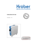
1
Kröber O2-4.0
Index
4.2 Design ........................................................................................................................ 65
5 Technical data ................................................................................................................. 67
6 Transport, packaging and storage................................................................................. 69
6.1 Transport inspection ................................................................................................... 69
6.2 Storage ....................................................................................................................... 69
7 Taking into service ......................................................................................................... 70
7.1 Before assembling ...................................................................................................... 70
7.2 Choosing the location ................................................................................................. 71
7.3 Assembly .................................................................................................................... 72
7.3.1 Without external humidification ............................................................................. 73
7.3.2 With external humidification .................................................................................. 76
8 Operation ......................................................................................................................... 79
8.1 Taking into service ...................................................................................................... 79
8.2 Adjusting the oxygen volume flow ............................................................................... 80
8.3 Status messages and alarms ...................................................................................... 82
8.3.1 Status messages .................................................................................................. 82
8.3.2 Status message .................................................................................................... 82
8.3.3 Alarm priorities...................................................................................................... 82
8.3.4 Alarm categories ................................................................................................... 83
9 Maintenance .................................................................................................................... 86
9.1 Safety ......................................................................................................................... 86
9.2 General notes ............................................................................................................. 86
9.2.1 Cleaning ............................................................................................................... 86
9.2.2 Disinfecting ........................................................................................................... 86
9.3 Maintenance plan ....................................................................................................... 87
9.4 Maintenance work ....................................................................................................... 89
10 Spare parts .................................................................................................................... 91
11 Appendix ....................................................................................................................... 92
11.1 EMC regulations ....................................................................................................... 92
11.1.1 Electromagnetic compatibility, interference emission .......................................... 92
11.1.2 Electromagnetic compatibility, interference emission .......................................... 93
11.1.3 Recommended safety distances ......................................................................... 96
11.2 Explanation of symbols on the unit ............................................................................ 97
52
Kröber O2-4.0
Index
12 Index .............................................................................................................................. 99
53
Kröber O2-4.0
Index
54
Kröber O2-4.0
Preliminary statement
1 Preliminary statement
Your doctor has found that you require an additional oxygen supply. With the Kröber O2 4.0
you received a German brand product for oxygen supply, which has been developed on the
basis of the latest knowledge in both medical engineering and electronics. Permanent quality
inspections ensure uniform quality on the highest level.
The Kröber O2 4.0 is a highly reliable oxygen concentrator , intended for use in homes or at
home, as well as for clinical applications.
However, should problems arise with the Kröber O2 4.0, you may contact your dealer at any
time.
This medical care product from Kröber is labelled with the CE-sign according to MDD
(Medical Device Directive ).
Only use the Kröber O2 4.0 after a medical indication and only in compliance with
the doctor's orders by following these instructions for use.
If side effects or extreme health restrictions occur during the therapy, you should
immediately consult your doctor.
55
Kröber O2-4.0
General
2 General
2.1 Information in these instructions for use
These instructions for use describe the installation, operation and maintenance of the unit.
Strict compliance with the stated notes on safety and instructions for use is a prerequisite for
safe and proper work with the unit.
Moreover, compliance with the accident prevention instructions valid at the location of use
and the general safety regulations is mandatory.
This instruction manual is part of the product and should be kept near the unit so that it is at
any time available for personnel involved in installation, operation, maintenance and
cleaning.
The graphic illustrations in this manual may perhaps differ slightly from the actual design of
the unit.
56
Kröber O2-4.0
General
2.2 Type plate
The type plate of the Kröber O2 4.0 is attached to the back of the unit above the coarse dust
filter.
2.3 Liability and warranty
All details and notes for the operation, maintenance and cleaning of the unit are made to the
best of our knowledge taking into consideration our experience and knowledge gained up to
now.
We reserve the right to make technical changes to the machine dealt with in these
instructions for use within the context of ongoing development.
Translations are also carried out to the best of knowledge. We do not accept any liability for
errors in translation. The German version of the instructions for use, which is also delivered
with the unit, is the definitive version.
Texts and illustrations do not necessarily correspond to the scope of delivery. The drawings
and graphics are not to scale 1:1.
Read instructions for use carefully before starting operation of the unit!
The manufacturer will not assume liability for damage or disruptions that occur as a result of
non-compliance with the instructions for use.
Handing over these instructions for use to third parties is not permitted and results in the
obligation for compensation.
2.4 Warranty
We grant, in excess of the implied warranty the following extended warranty:
Warranty terms: maximum 30,000 operating hours or 5 years from the date of purchase on
all functional parts (e.g. compressor, electronic circuit board, solenoid technology, etc.). The
first reached condition (30.000 hours or 5 years) applies.
Condition precedent to the extended warranty is the periodic maintenance according to the
Technical Service Manual.
Extent of warranty: the free-of-charge replacement of defective parts. The defective parts
must be submitted to us for inspection of warranty claims. For processing the warranty claim,
the serial number as well as date of purchase and the operating hours of the affected device
must be stated. If devices are sent to us for warranty repair free of charge, we will also cover
the labor costs for any warranty repairs. Locally resulting travel and service expenses are not
covered by us.
Excluded from this warranty are: filters and zeolites, damage from improper handling and
mechanical damage of parts (e.g. transport damage).
57
Kröber O2-4.0
General
2.5 Explanation of symbols
Important safety and equipment related notes in these instructions for use are highlighted by
symbols. These notes must be strictly adhered to in order to avoid accidents, personal
injuries and damage to property.
WARNING!
This symbol warns of dangers that can lead to adverse effects on health,
injuries, permanent physical damage or to death.
Strictly comply with all notes regarding work safety, and be particularly careful in
these situations.
WARNING! Danger of electric current!
This symbol draws attention to dangerous situations involving electrical
currents. There is a danger of serious injury or death if the safety notes are not
complied with. The related work may only be carried out by qualified electricians.
ATTENTION!
Information highlighted with this symbol must be strictly complied with in order
to avoid damage to the machine, malfunction and/or breakdown.
NOTE!
This symbol highlights hints and information to be observed for efficient and nondisrupted operation of the unit.
58
Kröber O2-4.0
General
2.6 Copyright protection
These instructions for use are to be treated confidentially. They should only be used by
persons who have been authorized accordingly. It may only be passed on to third parties
with the written consent of the manufacturer.
All documents are protected by copyright protection law.
It is not permissible to pass on or reproduce the documents, either as a whole or excerpts
thereof, to evaluate or communicate their content, unless explicitly entitled to do so. Any
violations are liable to prosecution and require compensation.
We reserve the right to exercise industrial property rights.
2.7 Return and waste disposal
–
If the unit has been delivered through a parcel service and not directly by a dealer you
should keep the packaging material for possible service instances.
–
If there is no corresponding agreement regarding the return of packing material, then
the packing material remains with the customer. He is responsible for environmental
waste disposal in accordance with the applicable waste disposal legislation.
–
After use the unit may be returned to the dealer, who is then responsible for proper
disposal of the unit.
–
Do not dispose of the unit into the domestic household waste.
–
Non-infectious used accessories (e.g. nasal cannula) can be disposed of as domestic
waste.
–
Infectious accessories (e.g. nasal cannula of an infected user) must be disposed of
through a specially approved waste disposal company. Addresses are available from
your local municipality.
2.8 Customer service
Service work should normally be carried out by your local authorized dealer.
You can contact Kröber Medizintechnik GmbH as follows:
Office hours:
Mo-Thu 7.30 a.m. - 4.00 p.m., Fri 7.30 a.m. - 2.00 p.m.
Address:
Kröber Medizintechnik GmbH
Salzheck 4
D-56332 Dieblich
Germany
Phone:
+49-2607-94040
Fax:
+49-2607-940422
Internet:
www.kroeber.de
eMail:
[email protected]
59
Kröber O2-4.0
Safety
3 Safety
This section provides an overview over all important safety aspects for safe and trouble-free
operation of the unit.
The individual chapter additionally contain actual safety notes highlighted with symbols,
which will help to avoid immediate dangers.
3.1 General
The machine is built according to the currently applicable rules of technology and is safe to
operate.
However, dangers may still arise from the unit if it is incorrectly operated or used for
purposes it is not intended for.
Any persons using this unit must have read and understood these instructions before starting
operation. This also applies if the person in question has already worked with just such a unit
or similar equipment or was trained by the manufacturer.
Knowing the content of these instructions for use is a prerequisite for the avoidance of
mistakes and for safe and trouble-free operation of the unit.
Neither changes nor conversions may be carried out on the equipment, which have not been
explicitly authorized by the manufacturer, to avoid dangers and to ensure optimal
performance.
All safety decals and operating signs on the unit must be kept well legible at all times.
Damaged or illegible decals must be replaced immediately.
3.2 Customer’s responsibility
These instructions for use must be kept near the unit, so that it is available for the user at any
time.
Apart from the notes on safety mentioned in this manual, all generally valid safety and
accident prevention instructions must also be observed and adhered to.
The machine may only be operated in a technically perfect condition and if operationally
safe.
The information contained in the instruction manual is complete and must be adhered to
without limitation.
60
Kröber O2-4.0
Safety
3.3 Intended use
The operational safety of the unit is only assured when used for the purpose it is intended
for, as specified in the instructions for use.
The Kröber O2 4.0 solely intended for use within the scope of a non-life sustaining medical
therapy for the additional supply of oxygen. The unit may thereby be used in hospitals,
homes or at home.
The unit must only be used according to the medical indication and only in accordance with
the doctor's prescription by following these instructions for use
The intended use also includes the compliance with the assembly instructions, as well as the
notes on cleaning and maintenance of the unit.
Any other use of the unit beyond these limits is prohibited and is not considered as
unintended use! Claims of any kind against the manufacturer and/or his authorized
representatives resulting from damage caused by unintended use of the unit are
excluded. The customer is solely liable for any damage resulting from unintended use.
3.4 Dangers which may arise from the unit
The unit was subjected to a risk analysis. The resultant construction and design of the unit
corresponds to the current status of technology.
However, there is still a remaining risk!
The unit requires responsibly minded and cautious operation. Improper operation or
operation by unauthorized persons can endanger persons.
WARNING! Risk of health damage!
If an absolutely safe oxygen supply is required, it is strictly necessary to have a
second, independent oxygen source available as replacement (e.g. a mobile
oxygen savings system with an oxygen cylinder).
If the patient or the operator notices at any time that the available amount of
oxygen is not sufficient, you should immediately contact your dealer and/or
doctor.
WARNING! Risk of health damage!
Particular supervision is required if the unit is to be used in the vicinity of
children or bedfast persons. The unit must under no circumstances be used with
children without additional supervision!
WARNING! Danger of side effects!
Do not modify your device. You can endanger your health.
61
Kröber O2-4.0
Safety
WARNING! Danger caused by device modifications!
If side effects or extreme health restrictions occur during the therapy, you
should immediately consult your doctor.
WARNING! Fire hazard caused by oxygen!
Oxygen is vital, but in concentrators with only a few percentage points above the
normal oxygen content in the air it is a highly dangerous fire accelerant. There
are only a few materials which will not burn off like an explosion under a raised
concentration of oxygen.
Therefore:
62
–
Oxygen may only be handled by trained or specially instructed persons!
–
Follow all mandatory instructions for installing and use of fire-reducing
equipment such as the angular connector and FiresafeTM check valve.
–
The misuse of oxygen, e.g. to cool down or improve the ambient air, to cool
down and dust or blow off of persons, clothes, furniture etc. is dangerous
and therefore prohibited!
–
Smoking and handling ignition sources and open flames is prohibited when
working with oxygen!
–
Keep a minimum distance of 2 metres from all spark generating equipment
and open fire!
–
After having stayed in a possible oxygen saturated atmosphere you should
thoroughly aerate your cloths, because oxygen adheres to the clothes very
well! An ignition source, e.g. a burning cigarette, could easily cause
burning of your clothes.
–
Materials that do not burn in air may burn very vigorously and even
spontaneously in oxygen or oxygen enriched air. This already applies for
an enrichment of only a few percent!
–
Oil and grease (even creams and gels) can react in an explosion like
manner when coming in contact with oxygen. It is therefore mandatory to
keep the unit free of oil and grease!
–
Oxygen considerably increases the temperature of a flame and the speed of
combustion!
–
Do not fill the humidifier with flammable fluids!
Kröber O2-4.0
Safety
WARNING! Danger of electric current!
Electric energies can cause severe injury. Damaged insulation or components
cause a danger to life.
Therefore:
–
Work on the equipment must only be performed by trained professionals.
–
Pull the mains plug out before starting work on the unit!
–
Check mains leads for damage before every use.
ATTENTION! Observe high frequency safety!
Medical equipment can be influenced by (mobile) HF communication equipment
(e.g. mobile phones).
Do not use mobile radio equipment in the vicinity of the Kröber O2 4.0 as close
as 3.5 m.
ATTENTION! Observe electromagnetic compatibility!
Electrical medical equipment is subjected to stringent protective measures
concerning electromagnetic compatibility (EMC) and must be installed and
operated in accordance with the EMC information contained in the
accompanying documents. The following should be noted in particular:
–
Floors should be made of wood or concrete or should be covered with
ceramic tiles. If the floor is covered with a synthetic material, the relative
humidity must be at least 30%.
–
During operation the unit must therefore not be exposed to extremely
strong magnetic fields.
–
Magnetic fields at mains frequency must comply with the typical values
found in business or hospital environments.
ATTENTION! Keep the minimum distance!
The air intake of the Kröber O2 4.0 is located on the back side of the unit, the
following is therefore of importance:
–
There should be a minimum distance of 30cm from walls, curtains and
other large objects (e.g. cupboards), so that an unrestricted entry of air is
assured at the back of the unit.
–
The Kröber O2 4.0 oxygen concentrator must not be used directly beside or
even stacked with other equipment.
ATTENTION! Avoid overheating!
The unit is air cooled, in order to avoid overheating it must not be placed near
heaters, etc.
63
Kröber O2-4.0
Safety
3.5 What to do if a hose caught fire
Should a hose catch fire despite all protective measures, it is not enough to just switch the
unit off, because oxygen will continue to flow for a while after the unit has been switched off.
Take the following steps:
–
Pull the oxygen hose off the unit to interrupt the oxygen supply.
–
Choke the flames (e.g. with a blanket).
–
Ventilate well after extinguishing the fire, because a burning PVC-hose will emit
toxic gases.
The metal connection on the oxygen outlet acts as a fire inhibitor, preventing the flames from
spreading into the unit.
64
Kröber O2-4.0
Design and function
4 Design and function
4.1 General description
The Kröber O2 4.0 oxygen concentrator for has been optimized for the oxygen supply at
home. The electronically controlled oxygen concentrator separates the oxygen from the
ambient air and supplies the user through the nasal cannula with highly concentrated
oxygen.
4.2 Design
1
Design:
2
1 Carrier handle
3
2 Control panel
4
3 Angle connection
4 Humidifier
5
5 Steerable castors
Fig. 26: Front
6 Mains lead
7 Coarse dust filter
6
7
Fig. 27: Back
8 On/Off-switch
9 Volume flow regulator
10
8
10 LC display
9
Fig. 28: Control panel
65
Kröber O2-4.0
Design and function
11 Service flap
11
12 Fuses
13 Air intake filter
12
13
Fig. 29: Service flap
66
Kröber O2-4.0
Technical data
5 Technical data
Model
Kröber O2 4.0
Classification acc. to MPG
IIa
Operating voltage
230 V, 50 Hz
Ambient operating conditions
Operation temperature: +5 to +40 °C
Storage temperature: -25 to +70 °C
Humidity: 15% - 93 % r.H., non-condensing
Atmospheric pressure: 700 to 1060 mbar
Sound pressure level
31 dB(A)
Power input
280 W
Coarse dust filter
in back of housing
Bacteria filter
behind service flap
Fuses
mains side: 2 x T3,15 AH 250 V
internal: 1 x T1,0AL 250 V
Interface
USB
WARNING! Unsafe
connections!
Connect only manufacturerauthorized devices to this USB port.
Weight
16 kg
Dimensions (HxWxD)
(53.5 x 20.3 x 52) cm without castors
Warranty
30.000 hours, maximum 5 years (see chapter
2.4)
O2-concentration
1 to 4 l/min.
95 % - 3 %
4 to 5 l/min.
85 % +/- 3 %
Status display O2-concentration
82% status display
(at operating temperature)
60% deficiency display
max. recommended volume flow
5 l/min
Volume flow (at 0 or 7kPa)
1 - 5 l/min acc. to pre-setting
max. output pressure:
35 kPa
Overpressure relief
200 kPa (oxygen reservoir)
67
Kröber O2-4.0
Technical data
250 kPa (compressor)
O2% characteristic, at a counter pressure
of 0 kPa, O2 concentration in %,
dependent from height (m)
% O2 - Volume Flow
96
94
O2%
92
0
90
2000
4000
88
86
84
0
1
2
3
Volume flow lpm
68
4
5
6
Kröber O2-4.0
Transport, packaging and storage
6 Transport, packaging and storage
The following should be noted when transporting the Kröber O2 4.0:
–
The unit should only be shipped and transported in its original packaging.
–
For transport, e.g. by car, the unit may stand upright or lay on one of the two
large flat sides.
–
Open the transport box from the top. Do not stand the transport carton upside
down or on one of its narrow sides.
6.1 Transport inspection
It is highly recommended to check the complete delivery for completeness and possible
transport damage, immediately after receipt.
In case of externally detectable transport damage you should not accept the delivery, or only
with reservation. Acknowledge the receipt only with reservation (e.g. on the freight
document). Specify the expected damage and inform the manufacturer immediately.
Hidden damage should be claimed immediately after detection, because damage claims can
only be lodged within the applicable claims periods.
The packaging material should be saved, it may be needed if the unit has to be returned.
6.2 Storage
If the package is to be stored before it is taken into service, please observe the following
instructions:
–
Store in a dry environment. Relative humidity: max. 93 % without condensation.
–
It must be assured that the package is not stored outdoors.
It must also be assured that the floor used for storage is dry over the entire storage
period.
–
Storage temperature -25 to +70°C.
–
Store in a dust-free environment.
–
Avoid mechanical shocks and damages.
69
Kröber O2-4.0
Taking into service
7 Taking into service
7.1 Before assembling
Check before assembling whether all components needed for correct operation are available.
NOTE!
Contact the manufacturer or the local service provider if help is needed during
operation or maintenance. The address of the manufacturer can be found on page
Fehler! Textmarke nicht definiert.. The address of the manufacturer should have
been disclosed during initial training on the device.
The a.m. organisations should also be contacted in case of unexpected events or
incidents.
Unit:
• Unit Kröber O2 4.0
• User manual
Fig. 30: Scope of delivery 1
Weitere Bestandteile:
1 Coarse dust filter
2 Humidifier
3 FireSafeTM check valve
4 Angular connector
2
1
3
4
Abb. 31: Scope of delivery 2
5 Nasal cannula for oxygen 2m
6 Nasal cannula for oxygen 5m
7 Oxygen safety hose 15m
5
6
7
8 Wall bracket for humidifier
9 Oxygen safety hose 0.33m
8
9
Abb. 32: Scope of delivery 3
70
10
11
10 Angular connector
11 Hose connector „christmas tree style“
Kröber O2-4.0
Taking into service
7.2 Choosing the location
Please consider the following when choosing the location:
–
The unit should have 30cm clearance from any walls, curtains and other large objects
(e.g. cupboards), to ensure unrestricted entry of air through the back of the unit.
–
The unit is air cooled. It must therefore not be placed near heaters, etc. At such a
location there is a risk of overheating.
–
The unit should be operated only in places where it is not impaired by air pollution or
smoke.
NOTE!
The unit can be safely lifted and moved by the carrier handle on top of the unit.
ATTENTION! Ensure a sufficient air supply!
Ensure that the air inlet of the Kröber 02 4.0 oxygen concentrator is located in a
well-vented spot.
The Kröber O2 4.0 oxygen concentrator must not be operated directly next to or
even stacked with other equipment. Ensure a sufficient distance from the walls,
etc.!
71
Kröber O2-4.0
Taking into service
7.3 Assembly
There are generally two possible ways to use the unit.
1
The unit is standing next to the user during use.
2
The user uses the "Set for external humidification". In this case the unit can stand in
another room.
ATTENTION!
The FireSafe Nozzle is a thermal fuse designed to stop the flow of oxygen in the
event that the downstream PVC tube is ignited. In doing so, the fire in the PV
tube is inclined to extinguish because PVC will not normally burn in air. The
FireSafe Nozzle is fitted directly to the outlet of each oxygen delivery device,
typically an oxygen flowmeter or the outlet of an oxygen concentrator!
Read through this entire chapter before installing this FireSafe Nozzle. As with
all medical equipment, attempting to use or install this device without a thorough
understanding of its operation and limitations may result in patient or user injury
1. This device is intended to be fitted to the outlet of a medical oxygen or oxygen
concentrator where breathing circuits that have low static operating pressures
not exceeding those stated in the device specification. It must not be used for
other applications.
2. This device is a flow direction sensitive device. It must be place with respect
to the correct flow direction; otherwise it is ineffective and does not protect the
patient in case of fire.
3. Do not install this device near an open flame or near a source of excessive
heat that is likely to exceed 40°C.
4. Oxygen is not flammable but the presence of oxygen will drastically increase
the rate and severity of combustion. Oil and/or grease in the presence of oxygen
become highly combustible. Do not use oil or grease on this device. In particular,
do not lubricate the seals or hose barb connector!
5. Never administer oxygen or undertake oxygen therapy while smoking or when
near an open flame.
72
Kröber O2-4.0
Taking into service
7.3.1 Without external humidification
If the unit is to stand next to the user, it is started up as follows:
1 Insert the mains lead into a
professionally grounded socket.
ATTENTION!
The Kröber O2 4.0 is only
designed for operation on a 230
Volt, 50Hz mains network.
Fig. 33: Mains lead
2 The metal oxygen outlet is installed
using a wrench (metric size 17).
Fig. 34: Angle connection
3 Fill the humidifier up to the top
MAX.-mark (1).
1
Fig. 35: Humidifier Max.-mark
73
Kröber O2-4.0
Taking into service
4 Fasten the humidifier on the
angular connection (1).
1
5 Connect the 0.33m oxygen hose to
the humidifier outlet (2).
2
Fig. 36: Humidifier assembly
1 Plug the FireSafe Nozzle in oxygen
flow direction into the nasal
cannula.
Nasal cannula
Fig. 37: Connection to the nasal cannula
ATTENTION!
Observe flow direction
indicated by the arrow!
ATTENTION!
For the best protection of the
patient, place the FireSafe
Nozzle in the oxygen tubing
routing as close to the patient
as possible!
2 Connect the other terminal to the
short oxygen tubing (0.33 m).
Nasal cannula
O2 tubing
Fig. 38: Connection with the O2 tubing
74
Kröber O2-4.0
Taking into service
3 Connect the oxygen tubing to the
humidifier.
NOTE!
The humidifier can be used
directly at the oxygen concentrator
or with the kit for external
humidification (near to the
patient).
Fig. 39: Connection with the humidifier
WARNING! Danger of tripping over!
On the back of the Kröber O2 4.0 you will find a winding device for the mains
lead. This should be used when the unit is out of use, to avoid any danger of
tripping over.
75
Kröber O2-4.0
Taking into service
7.3.2 With external humidification
If the unit does not need to stand next to the user, the installation is carried out as follows:
1 Insert the mains lead into a
professionally grounded socket.
ATTENTION!
The Kröber O2 4.0 is only
designed for operation on a 230
Volt, 50Hz mains network.
Fig. 40: Mains lead
2 Screw the angle connection to the
oxygen outlet of the Kröber O2 4.0 with
a wrench (metric size 17).
Fig. 41: Adapter for ext. humidification
3 Connect the oxygen outlet
connector.
Fig. 42: Oxygen outlet connector
76
Kröber O2-4.0
Taking into service
4 Connect the 15m-oxygen safety tubing
to the connector.
Fig. 43: Oxygen outlet connector
5 Fill the humidifier up to the top MAX.mark (1).
1
Fig. 44: Humidifier Max.-mark
1
2
3
Fig. 45: Humidifier assembly
6 Screw the angle adapter (1) to the
humidifier.
7 Plug the 15 m safety hose for oxygen
(extension hose) onto the angle
adapter (2).
8 Push the 0.33-m safety hose for
oxygen onto the outlet connector of the
humidifier (3).
77
Kröber O2-4.0
Taking into service
9 Stand the humidifier into the bracket
(1).
NOTE!
The bracket has the function of
preventing the humidifier from falling
over. It is therefore recommended to
mount the bracket to a wall, a
cupboard, etc.
1
Fig. 46: Humidifier bracket
1 Plug the FireSafe Nozzle in oxygen
flow direction into the nasal cannula.
Nasal cannula
ATTENTION!
Observe flow direction indicated
by the arrow!
Fig. 47: Connection to the nasal cannula
ATTENTION!
For the best protection of the
patient, place the FireSafe Nozzle
in the oxygen tubing routing as
close to the patient as possible!
2 Connect the other terminal to the
short oxygen tubing (0.33 m).
Nasal cannula
O2 tubing
Fig. 48: Connection with the O2 tubing
WARNING! Danger of tripping over!
On the back of the Kröber O2 4.0 you will find a winding device for the mains
lead. This should be used when the unit is out of use, to avoid any danger of
tripping over.
78
Kröber O2-4.0
Operation
8 Operation
WARNING! Health risk!
Inappropriate use of the Kröber O2 4.0 can lead to severe personal and/or
material damage.
You should therefore only start up the unit in strict compliance with the
instructions for use and the notes on safety.
8.1 Taking into service
1 Start the unit by actuating the mains
switch (1) on top of the unit.
– The Kröber O2 4.0 runs a self-test.
1
– The oxygen production starts after the
self-test.
– The LC-display continuously shows the
current oxygen volume flow and the
equipment status.
Fig. 49: Control panel
NOTE!
During the start-up phase the
oxygen alarm appears for 2 minutes.
This alarm should disappear after
two minutes. If this does not happen,
the unit may be defective.
After maximum 5 min, the unit will
reach its complete performance
according to the Technical
Specifications.
During the start-up phase the unit
also shows the operating hours. This
information disappears after 30
seconds.
– Information concerning the operating
status of the unit can be found in the
display.
Fig. 50: LC display
79
Kröber O2-4.0
Operation
2 Wear your nasal cannula.
Insert both cannula openings into your
nose.
Place both feed hoses over your ears.
Pull the sling with the sliding piece tight
under your chin.
Fig. 51: Nasal cannula
WARNING! Danger of
strangulation!
Care for a straight oxygen hose
routing to minimize the risk of
strangulations!
WARNING! Skin
irritations!
Care for a good fit of the nasal
prongs to minimize skin irritation
caused by movements and shifts
of the prongs !
WARNING! Risk of health damage!
Do not smoke while operating the Kröber O2 4.0! Oxygen must NOT be used near
open fire, sparks, glowing objects, etc.!
8.2 Adjusting the oxygen volume flow
1 Press the adjustment regulator (1) for
at least 2 seconds.
1
Fig. 52: Adjusting the volume flow
– When a signal sounds and the volume
flow indication in the LC display flashes
the adjustment mode has been
activated.
2 Change the volume flow by turning
the adjustment regulator. Turning
clockwise increases the volume flow;
turning the regulator anti-clockwise
reduces the volume flow.
NOTE!
80
Kröber O2-4.0
Operation
Perform the following steps to adjust:
0 - 2 l/min in steps of 0.1
2 - 4 l/min in steps of 0.2
4 - 5 l/min insteps of 0.5
3 The settings are accepted by pressing
the adjustment regulator again. The
input is once again acknowledged by
an audible signal.
NOTE!
The supplier may have restricted the
available volume flow range to
customized settings, such as 1 -4
lpm.
NOTE!
It may take up to 2 minutes until the actual volume flow corresponds with the setting. If
the output is closed, the output pressure can increase up to 0.35bar. The maximum
gas output temperature is maximum 6 degree higher than the ambient temperature.
NOTE!
After adjusting the oxygen flow setting, the alarms and status messages for oxygen
concentration and volume flow deviations are deactivated for approximately one minute
until the unit has reached a steady state. During this period alarms are muted.
ATTENTION!
The unit has been designed for operation at altitudes of up to 2000 m above seal
level. If the unit is used beyond this specification, compliance with the specified
performance data can no longer be guaranteed.
81
Kröber O2-4.0
Operation
8.3 Status messages and alarms
8.3.1 Status messages
NOTE!
Status messages are NOT accompanied with acoustical warning signals!
8.3.2 Status message
Status message /
LC display
Description
Oxygen status
alarm
The oxygen concentrator oxy 6000 is equipped with an
innovative multi-function sensor to monitor the oxygen
concentration of the oxygen output.
If this drops below 82%, the oxygen status alarm is triggered.
Countermeasures
– Check humidifier and hoses for leaks
– Inform the customer service.
NOTE!
According to the specifications of the oxy 6000, the oxygen
status alarm is an allowed situation and not an error state
for volume flow setting of greater than 5.0 lpm.
8.3.3 Alarm priorities
We differentiate between two alarm priorities:
Alarm priority
Description
Medium priority:
Quick countermeasures by the user are required.
Low priority:
Utmost attention of the user is required.
NOTE!
The alarm priorities can audibly be differentiated by different alarm sound sequences.
With a higher priority the number of alarm signals per unit of time increases.
82
Kröber O2-4.0
Operation
8.3.4 Alarm categories
Alarm category /
LC display
Description
Temperature alarm
Medium priority
The operating temperature inside the concentrator is too high.
Countermeasures:
– The unit should be switched off immediately.
– Check whether the air flow into the unit is restricted. Also
make sure that the unit has a sufficient clearance to other
objects (wall, cupboard, etc.).
– It may be necessary to replace the coarse dust filter in the
back wall of the unit. Further information concerning this
matter can be found in the section "Maintenance".
NOTE!
The oxygen supply is immediately stopped to protect the
patient. However, the compressor keeps on running.
System alarm
Medium priority
Micro-processor fault.
Countermeasures
– Switch off the unit immediately and inform the customer
service.
NOTE!
Output and generation of oxygen is stopped for safety
reasons.
83
Kröber O2-4.0
Operation
Alarm category /
LC display
Description
Mains failure alarm
Medium priority
The power supply for the unit is interrupted. This causes
immediate function failure of the oxy 6000!
Countermeasures
The following should be checked:
– Is the mains lead properly plugged into the socket?
– Has a fuse tripped? Check the fuse, replace if necessary.
NOTE!
Further information concerning checking the equipment
fuse of the oxy 6000 can be found in section
"Maintenance".
Note
If a function test concerning the mains failure alarm is to be
performed, you should proceed as follows:
– Pull the mains plug out of the socket.
– Switch on the unit.
The alarm works, if it is activated during the switch-on self-test.
NOTE!
If the alarm is triggered again after switching on, you
should inform the service department.
Lack of oxygen
alarm
Low priority
The oxygen concentrator oxy 6000 is equipped with an
innovative multi-function sensor to monitor the oxygen
concentration of the oxygen output.
If it is detected that the actual concentration does not match the
technical specifications, the alarm is activated. .
Countermeasures
– Check humidifier and hoses for leaks
– Inform the customer service.
84
Kröber O2-4.0
Operation
Alarm category /
LC display
Description
Sensor alarm
Low priority
There is a malfunction of the multi-function sensor, quantity and
concentration of oxygen cannot be determined with sufficient
accuracy.
Countermeasures
– Inform the customer service.
– Search for kinks of the oxygen supply tubing.
Volume flow alarm
Low priority
The actual volume flow does not match the setting.
Countermeasures
– Check whether the oxygen hose is buckled or squeezed.
– Check whether the accessories are correctly connected.
– Switch from longer tubing lengths to shorter tubing lengths.
NOTE!
If the volume flow output is too high, the output and
generation of oxygen is temporarily interrupted for safety
reasons.
WARNING! Risk of health damage!
Before resuming operation of the unit make sure that fault and cause of fault
have been rectified professionally.
85
Kröber O2-4.0
Maintenance
9 Maintenance
9.1 Safety
WARNING! Danger of electric current!
Before starting cleaning the unit must be switched off and disconnected from the
mains supply.
9.2 General notes
Cleanliness is a prerequisite for the success of an oxygen therapy at home. The specified
cleaning intervals must therefore strictly adhered to!
9.2.1 Cleaning
–
The unit should be cleaned with a damp (not wet) cloth, so that not fluid can enter.
–
You should only use commercial cleansing agents (e.g. washing-up liquid).
–
Aggressive cleansers must not be used under any condition!
9.2.2 Disinfecting
86
–
Any commercial disinfectant can be used for disinfecting. An up-to-date list is available
from the manufacturer.
–
The information for use issued by the disinfectant manufacturer must be strictly
complied with.
Kröber O2-4.0
Maintenance
9.3 Maintenance plan
Maintenance and cleaning work must be performed at regular intervals as specified in the
table below.
Interval
Cleaning work
daily
The humidifier must be cleaned and disinfected every
day.
daily
Nasal cannula should be disposed of and replaced
every day.
(in case of stationary or
ambulant use)
daily
Clean the nasal cannula.
(when used in homes or
for nursing care)
weekly
If the "Set for external humidification" is used, it must
be cleaned and disinfected every week.
every 14 days
The Kröber O2 4.0 must be cleaned with a damp cloth
and disinfected after.
earlier if necessary
every 4 weeks
Replace the coarse dust filter
every 4 weeks
Replace the nasal cannula.
(when used in homes or
for nursing care)
annually / after 5000
operating hours
Replace the air intake filter
NOTE!
With extremely dirty ambient air the filter must be
changed earlier.
with changing patients
The oxy6000 must be cleaned with a damp cloth and
disinfected after.
with changing patients
Replace the humidifier.
with changing patients
Replace the coarse dust filter
with changing patients
Replace the air intake filter
with changing patients
If the "Set for external humidification" is used, the
87
Kröber O2-4.0
Maintenance
Interval
Cleaning work
bracket must be cleaned and disinfected.
with changing patients
Replace the nasal cannula.
WARNING! Health risk!
In order to avoid cross infection, each user of
the Kröber O2 4.0 should wear his/her own
nasal cannula.
after infections
After an infection a new nasal cannula should be used
to prevent re-infection.
after service work
The Kröber O2 4.0 must be cleaned with a damp cloth
and disinfected after.
after service work
Nasal cannula should be disposed of and replaced by a
new one.
after service work
Replace the coarse dust filter
after service work
Replace the air intake filter.
Interval
Inspection
annually
Safety inspection
As average life times, we expect:
88
Article
Life time
Kröber O2-4.0
5 years min.
Humidifer
1 year
Oxygen hoses, nasal
cannula
1 month
Oarse dust filter
1 month
Device inlet filter
1 month
Kröber O2-4.0
Maintenance
9.4 Maintenance work
Maintenance work
Description
Cleaning the
humidifier
1 Unscrew the humidifier from the angle connection
2 Unscrew the lid from the humidifier and pour out any water
residues
3 Clean the humidifier with clear, warm water
4 Disinfect the humidifier as instructed
5 Fill fresh, distilled water into the humidifier
6 Turn the lid back on
7 Fasten the humidifier on the angle connection
NOTE!
When changing patients the humidifier must be disposed
of.
Sterile water system
If the Kröber O2 4.0 is used with a sterile water system, the
following must be observed:
– Sterile water systems must not be cleaned and refilled.
– The old water flask must be disposed of.
– The information provided by the sterile water producer
(package insert) must be observed!
Cleaning the nasal
cannula
1 Disconnect the hose of the nasal cannula from the Kröber O2
4.0.
2 Clean the nasal cannula in warm soapsuds. You may
alternatively use a weak acetic solution (10% vinegar, 90%
water).
3 Rinse the nasal cannula with lots of clear water.
4 Let the nasal cannula dry in air. The nasal cannula may only
be used again for the therapy after it has properly dried.
89
Kröber O2-4.0
Maintenance
Maintenance work
Description
Replacing the
coarse dust filter
1 Remove the coarse dust filter cover/bracket from the back of
the Kröber O2 4.0.
2 Remove the coarse dust filter and place a new filter into the
bracket.
3 Reattach the coarse dust filter cover.
Replacing the air
intake filter
1 Open the service flap.
2 Pull the old air intake filter with a slight twist off the filter off
the filter holder.
3 Plug the new filter element on.
4 Close the service flap.
Checking the
equipment fuse
WARNING! Danger of electric current!
Before checking the fuse switch off the unit and pull the
mains plug out of the socket.
1 Open the service flap.
2 Apply slight pressure and turn the fuse cover anti-clockwise.
3 Remove the fuse.
4 Inspect the fuse visually.
5 If necessary replace the fuse
6 Reinstall the fuse
90
Kröber O2-4.0
Spare parts
10 Spare parts
ATTENTION!
The intended use of the equipment is only possible when using approved
accessories. The use of accessories that have not been designed for use with
this unit, can severely affect the performance of the unit.
The following article numbers should be used when ordering:
Article number
Designation
KRO240.01
Instructions for use for Kröber O2 4.0, english
KRO2.02
Angle connector for humidifier
KRO2.03
Set for external humidification
KRO2.04
Hose connection with cap nut
KRO2.05
Bracket for humidifier
KRO2.06
Humidifier, for refilling
KRO2.07
Nasal cannula, 2 m
KRO2.08
Nasal cannula, 5 m
KRO2.09
Coarse dust filter for Kröber O2 4.0
KRO2.10
Air intake filter
KRO2.11
Bacteria filter
KRO2.94
FireSafe cannula
91
Kröber O2-4.0
Appendix
11 Appendix
11.1 EMC regulations
11.1.1 Electromagnetic compatibility, interference emission
Regulations and declaration of manufacturer Electromagnetic compatibility, interference emission
The Kröber O2 4.0 is intended for use in an environment as described below. The operator of the
Kröber O2 4.0 must make sure that the unit is operated in such an environment.
Measurement of interference
emission
Compatibility
Electromagnetic environment
- regulations
HF emissions acc. to
CISPR 11
Group 1
The Kröber O2 4.0 uses HF energy
solely for its own function. The HF
emission is therefore very low and
any interference with adjacent
electronic equipment is very
unlikely.
HF emissions acc. to
CISPR 11
Class B
Emission of harmonics acc. to
IEC 61000-3-2
Class A
Emission of voltage
fluctuations/flickers acc. to IEC
61000-3-3
compatible
Table 2: Electromagnetic compatibility, interference emission
92
The Kröber O2 4.0 is intended for
use in all facilities, including living
quarters and other environments
that are connected to the public
supply network, which also
supplies buildings used for the
purpose of living.
Kröber O2-4.0
Appendix
11.1.2 Electromagnetic compatibility, interference emission
Regulations and declaration of manufacturer Electromagnetic compatibility, interference emission
The Kröber O2 4.0 is intended for use in an environment as described below. The operator of the
Kröber O2 4.0 must make sure that the unit is operated in such an environment.
Electromagnetic
environment - regulations
Immunity test
IEC 60601 test level
Compatibility level
Discharge of static
electricity acc. to
IEC
61000-4-2
±6 kV contact
discharge
±6 kV contact
discharge
±8 kV Air discharge
±8 kV Air discharge
fast transient
electric
interference/bursts
acc. to IEC 610004-4
±2 kV for mains leads
±2 kV for mains
leads
Surge voltages acc.
to
IEC 61000-4-5
±1 kV Push-pull
±1 kV Push-pull
The quality of the supply
voltage should match the
typical office or hospital
environment.
Voltage dips, shortterm interruptions
and fluctuations in
supply voltage
< 5 % UT
limited functionality
The quality of the supply
voltage should match the
typical office or hospital
environment.
IEC 61000-4-11
40 % UT
Mains failure alarm
(60 % dip in UT) for 5
periods
Restart of unit
70 % UT
limited functionality
±1 kV for input/output
leads
±1 kV for input/output
leads
(>95 % dip in UT) for ½
period
(30 % dip in UT) for 25
periods
Magnetic field at a
supply frequency
(50 Hz) acc. to
IEC 61000-4-8
<5 % UT
Mains failure alarm
(95 % dip in UT) for 5 s
Restart of unit
3 A/m
Floors should be made of
wood or concrete or should
be covered with ceramic
tiles. If the floor is covered
with synthetic materials, the
relative humidity must be at
least 30%.
The quality of the supply
voltage should match the
typical office or hospital
environment.
NOTE:
UT is the a.c. supply voltage
before application of the test levels
Magnetic fields at mains
frequency must comply with
the typical values found in
office or hospital
environments.
93
Kröber O2-4.0
Appendix
Immunity test
IEC 60601 test level
Compatibility level
Electromagnetic
environment - regulations
Portable and mobile radio
equipment should not be
used closer to the Kröber
O2 4.0 and the leads, than
the safety distance
calculated by using the
equation applicable for the
transmission frequency.
Recommended safety
distance:
radiated HF
interference acc. to
IEC 61000-4-3
94
3 V/m
80 MHz to 2.5 GHz
3 V/m
d= 1.2 √P for 80 MHz to
800 MHz
d= 2.3 √P for 800 MHz to
2.5 GHz
Kröber O2-4.0
Appendix
Immunity test
IEC 60601 test level
Compatibility level
Electromagnetic
environment - regulations
directed HF
interference acc. to
IEC 61000-4-6
3 Veff
150 kHz to 80 MHz
3 Veff
d= 1.2 √P
with P being the rated
power of the transmitter in
Watt (W) acc. to the
specifications of the
transmitter manufacturer
and d being the
recommended safety
distance in metres (m).
According to an in-situ
a
examination the field
intensity of stationary radio
transmitters is with all
frequencies lower than the
b
compatibility level .
In environments marked
with the following symbol
interferences are possible:
NOTE 1 For 80 MHz the higher value is valid.
NOTE 2 These regulations may not apply in all situations. The propagation of electromagnetic waves is influenced by the
absorption and reflection by building, objects and persons.
a
The field intensity of stationary transmitters, such as base stations of radiophones and land mobile services, amateur
stations, AM- and FM-radio and television stations can theoretically not be exactly predetermined. In order to determine the
electromagnetic environment and the effect of stationary HF transmitters, it is recommend to examine the corresponding
location. If the detected field intensity at the location of the Kröber O2 4.0exceeds the compatibility level specified above, the
Kröber O2 4.0must be examined at a different location, with respect to its normal operation. If unusual performance
characteristics are detected, it may be necessary to apply additional measures, such as reorientation or relocation of the
Kröber O2 4.0.
b
Beyond the frequency range from 150 kHz to 80 MHz the field intensity is less than 3 V/m.
Table 2: Electromagnetic compatibility, interference emission
95
Kröber O2-4.0
Appendix
11.1.3 Recommended safety distances
Recommended safety distances between portable and
mobile HF communication equipment and the Kröber O2 4.0
The Kröber O2 4.0 is intended for operation in an electromagnetic environment with controlled HF
interferences. The customer or user of the Kröber O2 4.0can help to avoid electromagnetic interferences by
maintaining minimum distances between the portable and mobile HF communication equipment (transmitters)
and the Kröber O2 4.0, according to the maximum output power of the communication equipment, as
recommended below .
Rated power of transmitter
Safety distance acc. to transmitting frequency
W
m
150 kHz to 80 MHz
80 MHz to 800 MHz
800 MHz to 2.5 GHz
d=1.2√P
d=1.2√P
d=2.3√P
0,01
0,12
0,12
0,23
0,1
0,38
0,38
0,73
1
1,2
1,2
2,3
10
3,8
3,8
7,3
100
12
12
23
For transmitters for which the rated power is not contained in the tale above, the distance can be calculated
using the equation for the corresponding column, whereby P represents the rated power of the transmitter in
Watt (W), specified by the transmitter manufacturer.
NOTE 1 For calculation of the recommended safety distance for transmitters in the frequency range from 80
MHz to 2.5 GHz an additional factor of 10/3 was used, in order to reduce the likelihood that a mobile/portable
communication unit, that has unintentionally been brought near the patient, will trigger an interference.
NOTE 2 These regulations may not apply in all situations. The propagation of electromagnetic waves is
influenced by the absorption and reflection by building, objects and persons.
Table 3: Recommended safety distances
96
Kröber O2-4.0
Appendix
11.2 Explanation of symbols on the unit
Symbol
Explanation
Attention, observe instructions for use!
Attention, observe instructions for use!
IP 21
Degree of protection for the ingress of liquids and small parts
Applied part type BF
Class II
Notified Body: TÜV Rheinland LGA Products GmbH
I/O
On / Off
Do not smoke !
No open fire !
No oil or grease !
Do not remove any covers!
97
Kröber O2-4.0
Appendix
Do not dispose of in household waste !
98
Kröber O2-4.0
Index
12 Index
A
G
Accessories ...........................................91
General description ............................... 65
Accident .................................................64
H
Adjusting the oxygen volume flow ..........80
Air intake filter ........................................66
Angle connection ...................................65
Assembly ......................................... 70, 72
C
Carrier handle ........................................65
Choosing the location ............................71
Cleaning intervals ..................................86
Cleanliness ............................................86
HF communication equipment ............... 63
Hose fire ................................................ 64
Humidifier .............................................. 65
I
Instructions for use ................................ 56
L
Liability .................................................. 57
Location ............................................... 63
Coarse dust filter....................................65
M
Control panel .........................................65
Mains lead ............................................. 65
Copyright protection ...............................59
Maintenance .......................................... 86
D
Maintenance plan .................................. 87
Dangers ........................................... 61, 64
Design ...................................................65
Disinfecting ............................................86
Maintenance work ................................. 89
Medical Device Directive ....................... 55
Mobile phones ....................................... 63
Display ...................................................65
O
E
Operation .............................................. 79
EMC ......................................................63
EMC regulations ....................................92
Entry of air .............................................71
Equipment fuse ......................................90
Explanation of symbols on the unit.........97
F
Fire hazard ............................................62
Oxygen .................................................. 62
Oxygen concentrator ............................. 55
Oxygen cylinder..................................... 61
Oxygen savings system......................... 61
Oxygen supply....................................... 55
R
Regulator............................................... 65
Function .................................................65
S
Fuses .....................................................66
Safety .................................................... 60
Safety during maintenance .................... 86
99
Kröber O2-4.0
Index
Service flap ........................................... 66
Transport carton .................................... 69
Side effects ................................ 55, 61, 62
Transport damage ................................. 69
Spare parts ........................................... 91
Transport inspection .............................. 69
Steerable castors .................................. 65
V
Sterile water system.............................. 89
Storage ................................................. 69
Switch ................................................... 65
Symbols ................................................ 58
T
Technical data ...................................... 67
Transport .............................................. 69
100
Volume flow ........................................... 65
W
Warranty................................................ 57
Waste disposal ...................................... 59