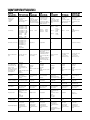
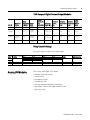
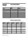
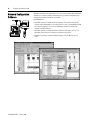
1
1768 CompactLogix Selection Guide 1768-L43 Logix Controllers Comparison Common Characteristics 1768 1756 ControlLogix CompactLogix Controller tasks: • Continuous • Periodic • Event • 32 tasks (only 1 continuous) • event tasks: supports all event triggers User memory 1756-L55M12: 750 KB 1756-L55M13: 1.5 MB 1756-L55M14: 3.5 MB 1756-L55M16: 7.5 MB 1756-L55M22: 750 KB 1756-L55M23: 1. 5 MB 1756-L55M24: 3.5 MB 1756-L61: 2 MB 1756-L62: 4 MB 1756-L63: 8 MB 1768-L43: 1756-L55M12: none 1756-L55M13: none 1756-L55M14: none 1756-L55M16: none 1756-L55M22: yes 1756-L55M23: yes 1756-L55M24: yes 1756-L6x: CompactFlash CompactFlash CompactFlash Nonvolatile user memory • 16 tasks (only 1 continuous) • event tasks: supports consumed tag trigger, EVENT instruction, axis, and motion event triggers 1769 CompactLogix 1789 SoftLogix5800 • 1769-L35x: 8 tasks • 1769-L32x: 6 tasks • 1769-L31: 4 tasks • only 1 continuous • event tasks: supports consumed tag trigger and EVENT instruction • 32 tasks (only 1 continuous) • event tasks: supports all event triggers, plus outbound and Windows events 1789-L10: 2 MB 1769-L31: 1769-L32x: 1769-L35x: 512 KB 750 KB 1.5 MB 1789-L30: 1789-L60: 2 MB 3 slots no motion 64 MB 5 slots 64 MB 16 slots none 1794 FlexLogix PowerFlex 700S with DriveLogix • 8 tasks (only 1 continuous) • event tasks: supports consumed tag trigger and EVENT instruction • 8 tasks (only 1 continuous) • event tasks: supports axis and motion event triggers 1794-L34: 256 KB 768 KB with memory expansion 512 KB yes yes (expansion memory) • 1 port RS-232 serial (DF1 or ASCII) • 2 slots for 1788 communication cards • 1 port RS-232 serial (DF1 or ASCII) • 1 slot for 1788 communication cards EtherNet/IP ControlNet DeviceNet serial Modbus via ladder routine DH-485 EtherNet/IP ControlNet DeviceNet serial Modbus via ladder routine DH-485 Built-in communication ports 1 port RS- 232 serial (DF1 or ASCII) 1 port RS- 232 serial (DF1 or ASCII) • 1769-L31 has 2 RS-232 ports (one DF1 only, other DF1 or ASCII) • 1769-L32C, -L35CR has 1 ControlNet port and 1 depends on personal RS-232 serial port (DF1 or computer ASCII) • 1769-L32E, -L35E has 1 EtherNet/IP port and 1 RS-232 serial port (DF1 or ASCII) Communication options (these options have specific products and profiles for their platform - other options are available via third party products and generic profiles) EtherNet/IP ControlNet DeviceNet Data Highway Plus Universal Remote I/ O serial Modbus via ladder routine DH-485 SynchLink EtherNet/IP DeviceNet serial Modbus via ladder routine DH-485 EtherNet/IP ControlNet DeviceNet serial Modbus via ladder routine DH-485 EtherNet/IP ControlNet DeviceNet serial Connections 64 over ControlNet (48 recommended) 128 over EtherNet/IP 64 TCP/IP 128 over EtherNet/IP 64 TCP/IP 32 over ControlNet 32 over EtherNet/IP 64 TCP/IP 64 over ControlNet (48 32 over ControlNet recommended) 32 over EtherNet/IP EtherNet/IP limited by 64 TCP/IP type and number of cards Controller redundancy full redundancy support not applicable not applicable not applicable controller hot backup via DeviceNet not applicable Native I/O 1756 ControlLogix I/O 1769 Compact I/O 1769 Compact I/O none 1794 FLEX I/O 1797 FLEX Ex I/O 1794 FLEX I/O 1797 FLEX Ex I/O Simple motion stepper servo via DeviceNet analog ac drive stepper servo via DeviceNet analog ac drive stepper servo via DeviceNet analog ac drive stepper servo via DeviceNet analog ac drive stepper servo via DeviceNet analog ac drive stepper servo via DeviceNet analog ac drive Integrated motion SERCOS interface analog interface with options: • quadrature encoder input • LDT input • SSI input SERCOS interface not applicable SERCOS interface analog interface with options: y quadrature encoder input y LDT input y SSI input not applicable 1 full servo 1 feedback axis Mounting and/or installation options 1756 chassis panel mount DIN rail panel mount DIN rail none panel mount DIN rail embedded Programming languages • relay ladder • structured text • function block • sequential function chart • relay ladder • structured text • function block • sequential function chart • relay ladder • structured text • function block • sequential function chart • relay ladder • structured text • function block • sequential function chart • external routines (Windows DLLs developed using C/C++) • relay ladder • structured text • function block • sequential function chart 32 over ControlNet 32 over EtherNet/IP 64 TCP/IP y y y y relay ladder structured text function block sequential function chart CompactLogix Selection Guide Logix Platforms 1 Allen-Bradley Logix platforms provide a single integrated control architecture for sequential, drives, motion, and process control. The Logix platforms provide a common control engine, programming software environment, and communication support across multiple hardware platforms. All Logix controllers operate with a multitasking, multiprocessing operating system and support the same set of instructions in multiple programming languages. One RSLogix 5000 programming software package programs all Logix controllers. And, as part of the Integrated Architecture, all Logix controllers offer the benefits of the Common Industrial Protocol (CIP) to communicate via EtherNet/IP, ControlNet, and DeviceNet networks. Contents Section 1768 CompactLogix System Layout the System Select 1769 I/O Modules Select Motion Control Requirements Select Network Communications Select Controllers Select Power Supplies Mount the System Select ViewAnyWare Products Select Software Summary See Page 2 3 5 15 21 29 39 43 45 47 55 1768-SG001A-EN-P -- March 2006 2 CompactLogix Selection Guide 1768 CompactLogix System CompactLogix is designed to provide a Logix solution for medium applications. Typically, these applications are machine-level control applications with motion axes, I/O requirements, and network connectivity requirements. What's New in Version 15: The 1768-L43 controller offers one built-in serial port. Install an optional 1768-ENBT communication module for EtherNet/IP communications. Install a 1768-M04SE SERCOS adapter module for motion control of SERCOS drives. y 1768-L43 controller y 1768-ENBT EtherNet/IP communication module A simple system can consist of a stand-alone controller with a single bank of I/O modules and DeviceNet communication. y 1768-M04SE motion interface module y 1768-PA3 power supply In a more complex system, add other networks and motion control. Multiple controllers can communicate across networks and share data. y Multiple controllers joined across networks y I/O in multiple platforms that is distributed in many locations and connected in as many three different banks of I/O modules 1768-SG001A-EN-P -- March 2006 CompactLogix Selection Guide 3 The 1768 CompactLogix controller combines both a 1768 backplane and a 1769 backplane. This provides the advantages of the 1768 architecture while retaining the advantages of 1769 I/O support. In the 1768 backplane: y 1768 power supply is the leftmost module y 1768 controller is the rightmost module y Two additional 1768 modules can be placed between the power supply and controller: - 1768-ENBT for EtherNet/IP communication (maximum of two) - 1768-M04SE for SERCOS motion control (maximum of one) y As many as eight local 1769 I/O modules (including a 1769-SDN) can be installed to the right of the 1768 controller The controller supports a maximum of 16 local 1769 I/O modules. As many as eight of the local modules can be attached to the 1768 controller. Install the remaining modules in one or two additional I/O banks. The additional banks are powered by standard 1769 power supplies (that is, 1769-PA4) and connected to the main rack using standard 1769 extension cables (that is, 1769-CRLx). Layout the System As you layout a system configuration, determine the network configuration and the placement of components in each location. Decide at this time whether each location will have its own controller. Use the 1768 CompactLogix system to distribute control among different locations. You can remotely control I/O and field devices from a central controller over an EtherNet/IP network. For example, this system layout defines Location A and Location B, which each require a unique 1768 CompactLogix controller. Location A and Location B each have their own local I/O modules. Location A also has some distributed DeviceNet I/O devices, so that location also needs a 1769-SDN DeviceNet scanner. Location B has SERCOS drives, so that location needs a 1768-M04SE adapter. A supervisory EtherNet/IP network interlocks Location A and Location B. 1768-SG001A-EN-P -- March 2006 4 CompactLogix Selection Guide Specify a System 9 Step 1 Follow these steps as you specify your CompactLogix system: See Select I/O devices Use a system spreadsheet to record: • Location of the device • Number of points needed • Appropriate catalog number • Number of points available per module • Number of modules 2 Select motion control and drives requirements To the system spreadsheet, add the number of motion modules. 3 Select communication modules To the system spreadsheet, add the number of communication modules. 4 Select controllers Select the appropriate controller based on: • Required controller tasks • Number of I/O points needed • Number of communication cards needed • Required controller memory 5 Select power supplies On the module spreadsheet, calculate power requirements. 6 Mount the system Determine whether to panel mount or DIN-rail mount the CompactLogix system. 7 Select ViewAnyWare products Determine the ViewAnyWare products that fit your operator interface needs. 8 Select software Determine the software products you need to configure and program your application. 1768-SG001A-EN-P -- March 2006 I/O module specifications Wiring systems Place I/O modules How I/O modules operate page 5 page 12 page 13 page 14 Motion overview SERCOS interface modules page 15 page 16 Network overview EtherNet/IP specifications DeviceNet specifications Serial specifications DH-485 specifications Controller specifications Determine memory requirements Control devices Communicate with other devices Logix system tasks PhaseManager applications Logix system connections page 22 page 23 page 25 page 27 page 28 page 29 page 30 page 32 page 33 page 34 page 34 page 35 1768 power supply specifications 1769 power supply specifications page 40 page 41 Mounting requirements page 43 RSView software PanelView Plus terminals VersaView industrial computers VersaView CE industrial computers Available software products Programming software Communication software Network configuration software Emulation software page 45 page 46 page 46 page 46 page 47 page 48 page 50 page 52 page 54 CompactLogix Selection Guide Step 1 - Select: y I/O modules 5 1769 Compact I/O Modules y 1492 wiring system (if you want to use a wiring system instead of the terminal block that comes with module) y PanelConnect modules and cables if connecting input modules to sensors y 1769-CRLx expansion cables for multiple banks of I/O modules The 1769 Compact I/O modules can be used as local I/O for a CompactLogix controller. Install the I/O modules on a panel with two mounting screws or on a DIN rail. The modules mechanically lock together by means of a tongue-and-grove design and have an integrated communication bus that is connected from module to module by a moveable bus connector. Each I/O module includes a built-in removable terminal block with finger-safe cover for connections to I/O sensors and actuators. The terminal block is behind a door at the front of the module. I/O wiring can be routed from beneath the module to the I/O terminals. Local I/O Performance The 1768 CompactLogix controller supports as many as 16 local 1769 I/O modules (maximum of 32 points per digital module and 8 points per analog module). As many as eight of the local modules can be attached to the 1768 backplane. The remaining eight modules can be in one or two additional I/O banks. The additional banks are powered by standard 1769 power supplies (that is, 1769-PA4) and connect to the main rack using standard 1769 extension cables (that is, 1769-CRLx). For the best local I/O performance in a 1768 CompactLogix system: y configure an individual RPI for each local 1769 I/O module. y you can select individual RPIs as fast as 1 millisecond. y use faster RPIs for time critical I/O without impacting overall 1769 I/O performance. y use Immediate Output (IOT) instructions for further reduction in I/O update times. I/O update times do not affect overall 1768 bus performance, such as motion performance or controller performance. Each 1769 I/O module has a distance rating. In 1769 systems, the distance rating is the number of modules between the specific module and the 1769 power supply. In a 1768 system, the distance rating is the number of modules between the specific I/O module and the 1768 controller. 1768-SG001A-EN-P -- March 2006 6 CompactLogix Selection Guide Digital I/O Modules Type of Module Input module Output module Description An input module responds to an input signal in the following manner: • Input filtering limits the effect of voltage transients caused by contact bounce and/or electrical noise. If not filtered, voltage transients could produce false data. All input modules use input filtering. • Optical isolation shields logic circuits from possible damage due to electrical transients. • Logic circuits process the signal. • An input LED turns on or off indicating the status of the corresponding input device. An output module controls the output signal in the following manner: • Logic circuits determine the output status. • An output LED indicates the status of the output signal. • Optical isolation separates module logic and bus circuits from field power. • The output driver turns the corresponding output on or off. Most output modules have built-in surge suppression to reduce the effects of high-voltage transients. Use an additional suppression device if an output is being used to control inductive devices, such as relays, motor starters, solenoids, or motors. Additional suppression is especially important if your inductive device is in series with or parallel to hard contacts, such as push buttons or selector switches. Add a suppression device directly across the coil of an inductive device to reduce the effects of voltage transients caused by interrupting the current to that device and to prolong the life of the switch contacts. When planning I/O communications, consider: y which Compact I/O modules to use. y where to place Compact I/O modules. y how Compact I/O modules operate. 1768-SG001A-EN-P -- March 2006 CompactLogix Selection Guide 7 1769 Compact Digital AC Input Modules Cat. No. Number of Inputs 1769-IA8I 8 individually isolated Input Delay Voltage Time, ON to Category/Type, Input Voltage Range OFF Current, OnState Input, Min. Current, OffState Input, Max. Backplane Current (mA) at 5V Power Supply Distance Rating 100 or 120V ac 79...132V ac @ 47...63Hz 20 ms 5 mA @ 79V ac 2.5 mA 90 mA 8 modules 1769-IA16 16 100 or 120V ac 79...132V ac @ 4763Hz 20 ms 5 mA @ 79V ac 2.5 mA 115 mA 8 modules 1769-IM12 12 200 or 240V ac 159...265V ac @ 4760Hz 20 ms 5 mA @ 159V ac 2.5 mA 100 mA 8 modules 1769 Compact Digital AC Output Modules Cat. No. Number of Outputs Leakage Current, OffVoltage State Output, Category/Type, Output Voltage Range Max 1769-OA8 8 100…240V AC 85...265 ac @ 47...63Hz 100…240V AC 85...265 ac @ 47...63Hz 1769-OA16 16 Backplane Current (mA) at 5V Power Supply Distance Rating 2.0 A @ 60 °C (140 °F) 4.0 A @ 30 °C (86 °F) 145 mA 8 modules 4.0 A @ 60 °C (140 °F) 8.0 A @ 30 °C (86 °F) 225 mA 8 modules Current per Output, Max. Current per Module, Max. 2.0 mA at 132V ac 2.5 mA at 265V ac 0.25 A @ 60 °C (140 °F) 0.50 A @ 30 °C (86 °F) 2.0 mA at 132V ac 2.5 mA at 265V ac 0.25 A @ 60 °C (140 °F) 0.50 A @ 30 °C (86 °F) Recommended Loading Resistor - To limit the effects of leakage current through solid state outputs, a loading resistor can be connected in parallel with your load. For 120V ac operation, use a 15 kΩ, 2W resistor. For 240V ac operation use a 15 kΩ, 5W resistor. 1768-SG001A-EN-P -- March 2006 8 CompactLogix Selection Guide 1769 Compact Digital DC Input Modules Number of Inputs Cat. No. Input Delay Voltage Time, ON to Category/Type , Input Voltage Range OFF Current, OnState Input, Min. Current, OffState Input, Max. Backplane Current (mA) at 5V Power Supply Distance Rating 1769-IQ6XOW4 6 24V dc, sinking or sourcing 10...30V dc @ 30 °C (86 °F) 8 ms 10...26.4V dc @ 60 °C (140 °F) 2 mA 1.5 mA 105 mA 8 modules 1769-IQ16 16 24V DC, sinking or sourcing 10...30V dc @ 30 °C (86 °F) 8 ms 10...26.4V dc @ 60 °C (140 °F) 2 mA 1.5 mA 115 mA 8 modules 1769-IQ16F 16 high-speed 24V dc, sinking or sourcing 10...30V dc @ 30 °C (86 °F) 1 ms 10...26.4V dc @ 60 °C (140 °F) 2 mA 1.5 mA 110 mA 8 modules 1769-IQ32 32 24V dc, sinking or sourcing 10...30V dc @ 30 °C (86 °F) 8 ms 10...26.4V dc @ 60 °C (140 °F) 2 mA 1.5 mA 170 mA 8 modules 1769-IQ32T 32 terminated 24V dc, sinking or sourcing 20.4...26.4V dc 3 mA 1.7 mA 170 mA 8 modules 8 ms 1769 Compact Digital DC Output Modules Number of Cat. No. Outputs Leakage Current, OffVoltage State Output, Category/Type , Output Voltage Range Max 1769-OB8 8 24V dc, sourcing 20.4...26.4 dc 1769-OB16 16 24V dc, sourcing 1769-OB16P 16 protected 1769-OB32 1769-OV16 Current per Output, Max. Backplane Current (mA) Current per Module, Max. at 5V Power Supply Distance Rating 1.0 mA @ 26.4V ac 2.0 A @ 60 °C (140 °F) 8.0 A @ 60 °C (140 °F) 145 mA 8 modules 20.4...26.4 dc 1.0 mA @ 26.4V ac 0.5 A @ 60 °C (140 °F) 1.0 A @ 30 °C (86 °F) 4.0 A @ 60 °C (140 °F) 8.0 A @ 30 °C (86 °F) 200 mA 8 modules 24V dc, sourcing 20.4...26.4 dc 1.0 mA @ 26.4V ac 0.5 A @ 60 °C (140 °F) 1.0 A @ 30 °C (86 °F) 4.0 A @ 60 °C (140 °F) 8.0 A @ 30 °C (86 °F) 160 mA 8 modules 32 24V dc, sourcing 20.4...26.4 dc 1.0 mA @ 26.4V ac 0.5 A @ 60 °C (140 °F) 1.0 A @ 30 °C (86 °F) 8.0 A @ 60 °C (140 °F) 16.0 A @ 30 °C (86 °F) 300 mA 8 modules 16 24V DC, sinking 20.4...26.4 dc 1.0 mA @ 26.4V ac 0.5 A @ 60 °C (140 °F) 1.0 A @ 30 °C (86 °F) 4.0 A @ 60 °C (140 °F) 8.0 A @ 30 °C (86 °F) 200 mA 8 modules 24V dc, sinking 10.2...26.4 dc 1.0 mA @ 26.4V ac 0.5 A @ 60 °C (140 °F) 1.0 A @ 30 °C (86 °F) 4.0 A @ 60 °C (140 °F) 8.0 A @ 30 °C (86 °F) 220 mA 8 modules 1769-OV32T 32 terminated 1768-SG001A-EN-P -- March 2006 CompactLogix Selection Guide 9 1769 Compact Digital Contact Output Modules Cat. No. Number of Outputs Voltage Category/Ty Voltage pe, Output Range Leakage Current, OffCurrent per State Current per Module, Output, Max Output, Max. Max. Power Backplane Backplane Supply Current (mA) Current (mA) Distance at 5V Rating at 24V 1769-IQ6XOW4 4 24V dc 5...265V ac 5...125V dc 0 mA 2.5 A 8.0 A 105 mA 50 mA 8 modules 1769-OW8 8 24V dc 5...265V ac 5...125V dc 0 mA 0.5 A @ 60 °C (140 °F) 16 A 1.0 A @ 30 °C (86 °F) 125 mA 100 mA 8 modules 1769-OW8I 8 individually isolated 24V dc 5...265V ac 5...125V dc 0 mA 0.5 A @ 60 °C (140 °F) 16 A 1.0 A @ 30 °C (86 °F) 125 mA 100 mA 8 modules 1769-OW16 16 24V dc 5...265V ac 5...125V dc 0 mA 2.5 A 205 mA 180 mA 8 modules 20 A Relay Contact Ratings These ratings apply to the digital contact output modules. Volts, Continuous Amps Amperes Max. per Point Make 240V ac 120V ac 2.5A 125V dc 1.0A 24V dc 2.0A Break 7.5A 0.75A 15A 1.5A Voltamperes Make Break IEC 947 NEMA ICS 2-125 1800VA 180VA AC15 C300 0.22A 28VA DC13 R150 1.2A 28VA ⎯ ⎯ Does not apply to the 1769-OW16 module. Analog I/O Modules Choose analog, thermocouple, or RTD modules. y Individually configurable channels y On-board scaling y Autocalibration of inputs y Selectable input filters y Over-range and under-range detection and indication y Input modules offer both single-ended or differential inputs y High accuracy rating 1768-SG001A-EN-P -- March 2006 10 CompactLogix Selection Guide 1769 Compact Analog Modules Cat. No. Number of Inputs Number of Outputs Resolution, Bits Signal Range Sensors Supported Backplane Current (mA) at 5V Backplane Current (mA) at 24V Power Supply Distance Rating — 105 mA 60 mA 8 modules 1769-IF4 4 — 14 bits (unipolar) 0…20 mA 4…20 mA 0…10V dc ±10V dc 0…5V dc 1…5V dc 1769-IF4I 4 individually isolated ⎯ 16 bits (unipolar) ±10.5V dc -0.5…10.5V dc -0.5...5.25V dc 0.5…5.25V dc ⎯ 145 mA 95 mA 8 modules 0…20 mA 4…20 mA 0…10V dc ±10V dc 0…5V dc 1…5V dc ⎯ 120 mA 70 mA 8 modules 1769-IF8 8 ⎯ 16 bits (unipolar) 1769-OF2 — 2 14 bits — — 120 mA 120 mA 8 modules ⎯ 4 current, individually isolated 16 bits (unipolar) 4…20 mA 0…20V mA ⎯ 145 mA 140 mA 8 modules ⎯ 145 mA 75 mA 8 modules 1769-OF4CI 1769-OF4VI ⎯ 4 voltage, individually isolated 16 bits (unipolar) -10…10V dc 0…5V dc 0...10V dc 1…5V dc 1769-OF8C ⎯ 8 current 16 bits (unipolar) 0…20 mA 4…20 mA ⎯ 145 mA 160 mA 8 modules 1769-OF8V ⎯ 8 voltage 16 bits (unipolar) ±10.5V dc -0.5…10.5V dc -0.5...5.25V dc 0.5…5.25V dc ⎯ 145 mA 125 mA 8 modules 2 individually isolated 8 bits plus sign7 individually isolated 0…10V dc ±10V dc 0…5V dc 1…5V dc — 120 mA 160 mA 8 modules — 100, 200, 500, 1000 Ω Platinum, alpha=385 100, 200, 500, 1000 Ω Platinum, alpha=3916 120 Ω Nickel, alpha=672 120 Ω Nickel, alpha=618 10 Ω Copper 604 Ω Nickel-Iron 518 0…150 Ω 0…500 Ω 0…1000 Ω 0…3000 Ω 100 mA 45 mA 8 modules — Thermocouple types: J, K, T, E, R, S, B, N, C 100 mA ±50mV ±100mV 40 mA 8 modules 1769-IF4XOF2 4 1769-IR6 6 1769-IT6 6, plus 2 cold junction sensors — — Input filter and configuration dependent — If the optional 24V dc Class 2 power supply is used, the 24V dc current draw from the bus is 0 mA. 7Sign is always positive. 1768-SG001A-EN-P -- March 2006 CompactLogix Selection Guide Specialty I/O Modules 11 Specialty I/O modules are available for more application-specific needs. 1769-HSC High-speed Counter Module Use the 1769-HSC when you need: y a counter module that is capable of reacting to high-speed input signals y to generate rate and time-between-pulses (pulse interval) data y as many as 2 channels of quadrature or 4 channels of pulse/count inputs Cat. No. Number of Inputs 1769-HSC 2 Number of Outputs Backplane Current (mA) at 5V External Power 4 425 mA Power Supply Distance Rating 19.2...31.2V dc 100 mA @ 24V dc 4 modules 1769-ARM Address Reserve Module Use a 1769-ARM address reserve module to reserve module slots. After creating an I/O configuration and user program, you can remove and replace any I/O module in the system with a 1769-ARM module once you inhibit the removed module in RSLogix 5000 programming software. Cat. No. Number of Inputs 1769-ARM — Number of Outputs Backplane Current (mA) at 5V Power Supply Distance Rating — 8 modules 60 mA Compact I/O to PowerFlex Drives The 1769-SMx modules provide direct 1769 platform connection to PowerFlex drives. Cat. No. Description Communication Rate Backplane Current (mA) Backplane Current (mA) Power Supply Distance Rating at 5V at 24V Compact I/O to DPI/SCANport Module connects to PowerFlex 7-class DPI: 1925 Kbps or 250 Kbps 1769-SM1 drives, other DPI-based host SCANport: 125 Kbps devices, and SCANport-based host devices such as 1305 and 1336 PLUS II drives 280 mA 60 mA per channel supplied by the 6 modules DPI/SCANport host Compact I/O to DSI/Modbus Module connects to PowerFlex 4-class 1769-SM2 drives and to other Modbus RTU slave devices, such as PowerFlex 7-class drives with 20-COMM-H RS485 HVAC adapters 350 mA 0 mA DSI: 19.2 Kbps Modbus RTU: 300...38.4 Kbps 4 modules 1768-SG001A-EN-P -- March 2006 12 CompactLogix Selection Guide 1492 Wiring Systems As an alternative to buying RTBs and connecting the wires yourself, you can buy a wiring system of: y interface modules (IFMs) that provide the output terminal blocks for digital I/O modules. Use the pre-wired cables that match the I/O module to the IFM. y analog interface modules (AIFMs) that provide the output terminal blocks for analog I/O modules. Use the pre-wired cables that match the I/O module to the AIFM. y I/O-module-ready cables. One end of the cable assembly is an RTB that plugs into the front of the I/O module. The other end has individually color-coded conductors that connect to a standard terminal block. 1667 PanelConnect Modules for Connecting Sensors 1768-SG001A-EN-P -- March 2006 A PanelConnect module and its sensor connection system connect sensors directly to I/O modules using convenient pre-built cables and connectors. The PanelConnect module mounts on the enclosure and creates the correct seal for the entry of the sensor connections. You do not need to seal the opening where the sensor cables enter the enclosure, create custom connectors, or wire to those custom connectors. CompactLogix Selection Guide Place Compact I/O Modules in a CompactLogix System 13 You can DIN-rail or panel mount the controller and I/O modules. The number of local I/O modules supported depends on the controller. This Controller Supports That Can Be In 1768-L43 16 local modules 3 separate banks Each 1769 I/O module has a distance rating. In 1769 systems, the distance rating is the number of modules between the specific module and the 1769 power supply. In a 1768 system, the distance rating is the number of modules between the specific I/O module and the 1768 controller. Select Expansion Cables The 1768 power supply supports as many as eight 1769 modules. If you have more 1769 modules, install them in one or two additional I/O banks. If you divide 1769 modules into multiple banks: y each bank can only contain 1769 I/O modules. y each bank needs its own, standard 1769 power supply, such as 1769-PA4. y use expansion cables to connect the banks. y the last I/O bank requires an end cap. How you orient I/O banks determines which expansion cables you need to connect the I/O banks. If You Add a: Second bank Third bank And Connect the Chassis: right to left right to right right to left right to right left to left Use This Cable: 1769-CRLx 1769-CRRx 1769-CRLx 1769CRRx 1769-CLLx Where x = 1 for 1 ft (305 mm) or 3 for 3.28 ft (1 m). 1768-SG001A-EN-P -- March 2006 14 CompactLogix Selection Guide Select End Caps The final I/O bank in the CompactLogix system needs an end cap on the end without the expansion cable. For a Right end cap Left end cap Order 1769-ECR 1769-ECL Plan Local and Remote (Distributed) I/O In addition to local I/O, the CompactLogix controller can control remote (distributed) I/O via the: y EtherNet/IP network using a 1768-ENBT communication module. y DeviceNet network using a 1769-SDN scanner module. While local I/O can be lower in cost and easier to configure, configuring distributed I/O offers: y More versatility in laying out your system y More communication options, such as DeviceNet, ControlNet, and EtherNet/IP networks y Ability to configure the listen-only communication format for remote I/O modules How Compact I/O Modules Operate The 1769 backplane is a master/slave backplane. All 1769 I/O modules in a CompactLogix system are scanned asynchronous to the program scan at a configurable Requested Packet Interval (RPI) rate. You configure an individual RPI for each local 1769 I/O module. The controller continually scans the control logic. One scan is the time it takes the controller to execute the logic once. Input data transfers to the controller and output data transfers to output modules asynchronous to the logic scan. Important: The CompactLogix 1769 and 1768 backplanes do not support Removal and Insertion Under power (RIUP). While the CompactLogix system is under power, any break in the connection between the 1768 power supply and the controller (such as removing the power supply, controller, or 1768 module) clears controller memory (including the user program). Any break between the 1768-L43 controller and 1769 I/O does not clear memory but causes a major fault in the controller. 1768-SG001A-EN-P -- March 2006 CompactLogix Selection Guide Step 2 - Select: y Size the motion application (use the Motion Analyzer) y How you want to interface the controller and drives y A SERCOS interface module y Associated cables y Select drives, motors, and accessories (use the Motion Analyzer) 15 Motion Control Requirements The Logix approach to motion control employs synchronized, distributed processing and provides a highly-integrated motion solution. Logix integrates sequential and motion control to bring unmatched flexibility to machine design and unprecedented efficiency to the manufacturing floor. RSLogix 5000 Enterprise series software supports a comprehensive set of embedded motion instructions that can be programmed using the relay ladder, structured text, or sequential function chart editors. The Logix architecture supports motion components that work in a wide variety of machine architectures. y The Kinetix integrated motion solution uses a SERCOS interface module to perform complex, multi-axis, synchronized motion. With a Kinetix system, you reap the full benefit of the integrated architecture because the integration doesn’t stop at the controller. This system integrates the drive, the motor, and even the actuator at a lower cost per axis of motion. y Networked motion provides the ability to connect via the DeviceNet network to a singleaxis drive to perform simple, point-to-point indexing. You need Ultraware software for drive and indexing configuration. Select a Motion Interface Communicate Directly to a Servo Drive The controller can control servo drives through these motion interfaces: If Your Application Requires: Rockwell Automation SERCOS interface drives Select This Motion Interface: 1768-M04SE Communicate Over a Network Some servo drives are supported through communication interface modules. The controller can communicate with these servo drives over these networks: Drives 1394 GMC drive and control 2098 Ultra3000 DeviceNet servo drive 2098 Ultra5000 intelligent positioning EtherNet/IP DeviceNet RS-232 Serial DH-485 no no yes yes no yes no no no yes yes no Each drive has different options you order for its supported communication networks. See the appropriate catalog or selection information for a drive to make sure you select the appropriate option when specifying a drive for a specific network. For more information on drives, motors, and accessories, see the Motion Control Selection Guide, publication GMC-SG001. 1768-SG001A-EN-P -- March 2006 16 CompactLogix Selection Guide Motion Performance The 1768 CompactLogix controller supports one 1768-M04SE SERCOS interface module for: y as many as four Kinetix drives and motors. y as many as two feedback axes. y as many as six virtual axes. In a motion application: y You can have as many as four axes per CompactLogix system. If your solution requires more than four Kinetix drives, consider the ControlLogix platform. y Trigger an event task via a registration input on a Kinetix drive and the motion task update. The SERCOS interface servo modules serve as a link between the controller and intelligent, servo drives. SERCOS is the IEC 61491 SErial Real-time COmmunication System protocol over a fiber optic medium. The SERCOS interface is a controller-to-digital drive interface designed for high-speed, real time, serial communications using noiseimmune, fiber-optic cables. SERCOS Interface Modules The SERCOS interface modules use a single, digital fiber optic link, which eliminates as many as 18 digital wires per axis. Detailed drive status information can be sent from drive to controller and from controller to drive. The modules are compatible with the RSLogix 5000 motion instructions set and axis configuration utilities. The motion instructions provide a wide range of motion capability, including point-point positioning, gearing, position and time-based camming, and multiaxis linear and circular motion. The SERCOS interface modules can connect to these servo drives: y 2094 Kinetix 6000 servo drive y 2098 Ultra3000 SERCOS servo drive y 1394C SERCOS drive y 8720MC spindle Number of Axes, Cat. No. per Module, Max. 4 real plus 2 feedback 1768-M04SE and 6 virtual Number of Modules per Controller Power Dissipation 1 module Certifications: UL, CSA (Class I, Division 2, Group A, B, C, D), CE 1768-SG001A-EN-P -- March 2006 5.04 W Backplane Current (mA) at 5V 969 mA Backplane Current (mA) at 24V 0 mA SERCOS Data Rate 4 Mbits or 8 Mbits per second CompactLogix Selection Guide 17 Typical Configuration - 2-Axis Motion with Ultra3000 Servo Drives y If you have an auxiliary feedback device that requires encoder feedback, change the Ultra3000 drives to Kinetix 6000 drives. y If you tie an incremental encoder to a 1769-HSC High-speed Counter module, you cannot use this input as one of the feedback-only axes or tie this input to the motion planner. 1768-SG001A-EN-P -- March 2006 18 CompactLogix Selection Guide Typical Configuration - 3-Axis Integrated Motion with Kinetix Servo Drives A 3-axis system with Kinetix drives supports: y execution of 4 axes per 1 ms. y velocity bandwidth > 400 Hz and current loop bandwidth > 1000 Hz. y high resolution, unlimited travel, and absolute feedback features. y two feedback ports per Kinetix drive. 1768-SG001A-EN-P -- March 2006 CompactLogix Selection Guide 19 Typical Configuration - 4-Axis Integrated Motion with Kinetix drives and LIM power interface A 4-axis system with Kinetix drives supports: y execution of 4 axes per 1 ms. y velocity bandwidth > 400 Hz and current loop bandwidth > 1000 Hz. y high resolution, unlimited travel, and absolute feedback features. y two feedback ports per Kinetix drive. y optional 2094 Line Interface Module (LIM) as the incoming power source for an entire control panel. 1768-SG001A-EN-P -- March 2006 20 CompactLogix Selection Guide Cables for Use with the SERCOS Interface Modules Both the transmitter and receiver connections use a F-SMA standard plug that conforms to the F-SMA screw type connector. Select one of these fiber optic cables to connect the SERCOS interface module to the drive. Cat. No. 2090-SCEPx-x (no jacket) 2090-SCVPx-x (standard jacket) 2090-SCNPx-x (nylon jacket) 2090-SCVGx-x Description Plastic Fiber Optic Cables 1000 μm plastic simplex fiber optic cable transmission range of 1...32 m. Allen-Bradley offers plastic, fiber-optic cable assemblies that come in a variety of jackets: • No jacket (Chlorinated Polyethylene) for use inside an electrical cabinet • A standard jacket (Polyvinyl Chloride) for use outside of electrical cabinets • A nylon jacket for use in harsh environments Glass Fiber Optic Cables7 200 μm glass fiber optic cable transmission range of 1...200 m. Allen-Bradley offers glass, fiber-optic cable assemblies that come with a standard jacket (Polyvinyl Chloride) for use in normal environments. The x-x determines the length in meters. Specify 0-1 for 0.1m, 0-3 for 0.3m, 1-0 for 1m, 3-0 for 3m, 5-0 for 5m, 8-0 for 8m, 10-0 for 10m, 15-0 for 15m, 20-0 for 20m, 25-5 for 25m, or 32-0 for 32m. 7The x-x determines the length in meters. Specify 50-0 for 50m, 100-0 for 100m, 150-0 for 150m, or 200-0 for 200m. 1768-SG001A-EN-P -- March 2006 CompactLogix Selection Guide Step 3 - Select: y Networks 21 Network Communications y Communication interfaces y Associated cables and network equipment You use separate interface modules to connect to different networks. y The 1768-L43 controller has a built-in serial port. y Add a 1768-ENBT module for EtherNet/IP communications. y Add a 1769-SDN scanner to connect to DeviceNet devices. The individual communication interface modules allow for more system flexibility, greater communications connections, and more distributed I/O connections. NetLinx Open Network Architecture NetLinx Open Network Architecture is the Rockwell Automation strategy of using open networking technology for seamless, top-floor to shop-floor integration. The NetLinxbased networks – DeviceNet, ControlNet, and EtherNet/IP – all use the Common Industrial Protocol, so they speak a common language and share a universal set of communication services. NetLinx architecture, part of the Integrated Architecture, seamlessly integrates all the components in an automation system from a few devices on one network to multiple devices on multiple networks including access to the Internet – helping you to improve flexibility, reduce installation costs, and increase productivity. y The EtherNet/IP network is an open industrial networking standard that supports implicit and explicit messaging and uses commercial, off-the-shelf Ethernet equipment and physical media. y The ControlNet network allows intelligent, high-speed control devices to share the information required for supervisory control, work-cell coordination, operator interface, remote device configuration, programming, and troubleshooting. y The DeviceNet network offers low-cost, high-speed access to plant-floor data from a broad range of plant-floor devices and a significant reduction in wiring. 1768-SG001A-EN-P -- March 2006 22 CompactLogix Selection Guide Select a Network If Your Application Requires • Plant management • Configuration, data collection, and control on a single, high-speed network • Time-critical applications with no established schedule • Data sent regularly • Internet/Intranet connection • Connections of low-level devices directly to plant floor controllers, without interfacing them through I/O modules • Data sent as needed • More diagnostics for improved data collection and fault detection • Less wiring and reduced start-up time than a traditional, hard-wired system • Modems • Supervisory control and data acquisition (SCADA) • Manipulate ASCII data • Connections to existing DH-485 networks You can configure your system for information exchange between a range of devices and computing platforms and operating systems. Select a CompactLogix controller with integrated communications or the appropriate communication device for the networks that meet your needs: Use This Network Select EtherNet/IP 1768-ENBT scanner DeviceNet 1769-SDN scanner 1761-NET-DNI interface 1769-ADN adapter Serial built-in serial port on all CompactLogix controllers 1769-ASCII module DH-485 built-in serial port with a 1761-NET-AIC A ControlNet option is not currently available for the 1768 CompactLogix controller, but it is planned to be available at the Logix V16 release. 1768-SG001A-EN-P -- March 2006 CompactLogix Selection Guide EtherNet/IP Network 23 The Ethernet Industrial (EtherNet/IP) network protocol is an open industrial networking standard that supports both real-time I/O messaging and message exchange. It emerged due to the high demand for using the Ethernet network for control applications. The EtherNet/IP network uses off-the-shelf Ethernet communication chips and physical media. The EtherNet/IP network provides excellent drive and I/O control performance along with HMI information processing and many commercial technologies. Select an EtherNet/IP Interface Select the appropriate controller and EtherNet/IP interface depending on the application and how the controller interacts with the devices: If Your Application • Controls I/O modules • Requires an adapter for distributed I/O on EtherNet/IP links • Communicates with other EtherNet/IP devices (messages) • Bridges EtherNet/IP links to route messages to devices on other networks Select this Interface Description 1768-ENBT The 1768-ENBT module: • controls I/O over an EtherNet/IP network. • routes messages to devices on other networks. • sends real-time, connected, peer-to-peer data between multiple controllers. • sends and receives email. • Sends and receives messages over the EtherNet/IP network 1761-NET-ENI interface, series B • Transfers small amounts of data over the EtherNet/IP network The 1761-NET-ENI series B interface module routes a DF1 message received from the attached controller to a compatible destination TCP/IP device. This is accomplished by using DF1 node addresses 0 to 49. The 1761-NET-ENI node addresses 100 to 149 store TCP/IP destination addresses. When the 1761-NET-ENI receives a write message to nodes 100 to 149, it stores the TCP/IP destination address in the corresponding map register. EtherNet/IP Interface Specifications Cat. No. 1768-ENBT Number of Modules per Controller Communication Rate Connections Supported, Max. 10/100 MB Each module supports a maximum of: • 128 Logix (CIP) connections (I/O two 1768 modules per and information) controller • 64 TCP/IP connections • 5000 messages/s 1761-NET-ENI 10/100 MB7 6 TCP/IP connections Connector Power Dissipation Backplane Current (mA) at 5V Backplane Current (mA) at 24V RJ-45 4.38 W 834 mA 0 mA — 0 mA 50 mA one interface per serial RJ-45 port Certifications: UL, CSA (Class I, Division 2, Group A, B, C, D), CE The 1768-L43 controller supports a maximum of two 1768 modules. 7The 1761-NET-ENI is an Ethernet to serial linking device. While 10 MB is the fastest communication rate supported by a 1761-NET-ENI device, the actual network performance depends on the maximum serial port connection speed. 1768-SG001A-EN-P -- March 2006 24 CompactLogix Selection Guide EtherNet/IP Product Compatibility Recipient EtherNet/IP PLC-5 or SLC 5/05 1785-ENET Processor Module EtherNet/IP PLC-5 or SLC 5/05 Processor information 1785-ENET Module Logix5000 Controller 1794-AENT FLEX I/O Adapter 1734-AENT POINT I/O Adapter 1761-NETENI Interface PanelView Plus EtherNet/IP RSLinx Terminal Software 1761-NETENI Interface information information not supported not supported information information information information information information information not supported not supported information information information information Logix5000 Controller information information information I/O data interlocking I/O data I/O data information information I/O data information information 1761-NET-ENI Interface7 information information information not supported not supported information information information information PanelView Plus EtherNet/IP Terminal information information information I/O data na na information na na information RSLinx Software information information information not supported not supported information na information information Originator For EtherNet/IP control: • a ControlLogix controller requires a 1756-ENBT or 1756-ENET series B scanner. • a FlexLogix controller requires a 1788-ENBT scanner. • a CompactLogix controller must be a 1769-L32E or 1769-L35E controller or be a 1768-L43 controller with a 1768-ENBT scanner. • the PC for a SoftLogix5800 controller requires appropriate hardware for Ethernet communications. 7To be an originator, the 1761-NET-ENI interface must connect to the other device through that device’s RS-232 port. Typical EtherNet/IP Configuration 1768-SG001A-EN-P -- March 2006 CompactLogix Selection Guide DeviceNet Network 25 The DeviceNet network is an open low-level network that provides connections between simple industrial devices (such as sensors and actuators) and higher-level devices (such as PLC controllers and computers). The DeviceNet network uses the proven Common Industrial Protocol (CIP) to provide the control, configure, and data collection capabilities for industrial devices. The DeviceNet network is a flexible network that works with devices from multiple vendors. Select a DeviceNet Interface If Your Application • Communicates with other DeviceNet devices (I/O and messages) • Requires explicit messaging • Uses the controller as a master or slave on the DeviceNet network • Uses the controller serial port for other communications • Requires higher performance than available from the 1769-NET-DNI interface • Communicates with other DeviceNet devices (messaging only) • Uses the controller only as a slave on the DeviceNet network • Does not use the controller serial port for other communications • Trades lower cost for lower performance than the 1769-SDN scanner Select This Interface Description 1769-SDN DeviceNet scanner The scanner acts as an interface between DeviceNet devices and the CompactLogix controller. The scanner lets the controller: • read inputs from slave devices. • write outputs to slave devices. • send and receive messages. 1761-NET-DNI interface The interface module links the CompactLogix controller to other devices on a DeviceNet network to: • download configuration data to a device. • monitor operational status of a device. • communicate with peer devices (messaging). • upload/download programs. • Accesses remote Compact I/O over a DeviceNet network 1769-ADN DeviceNet • Sends remote I/O data for as many as 30 modules adapter back to scanner or controller The adapter: • interfaces with as many as 30 Compact I/O modules. • communicates to other network system components (typically a controller or scanner and/or programming terminals). 1768-SG001A-EN-P -- March 2006 26 CompactLogix Selection Guide DeviceNet Interface Specifications Cat. No. Communication Rate Cable 90 mA @ 11V dc 110 mA @ 25V dc (N.E.C. Class 2) 1769-SDN 1761-NET-DNI 1769-ADN/B DeviceNet Power Requirements, Max. 125 Kbps 250 Kbps 500 Kbps Power Consumption (W) at 24V Backplane Current (mA) at 5V Backplane Current (mA) at 24V Power Supply Distance Rating 2.2 440 mA ⎯ mA 4 modules 0 mA 200 mA na 450 mA ⎯ mA 5 modules 450 mA ⎯ mA 4 modules 11…25V dc — Allen-Bradley part number 1485C-P1-Cxxx 90 mA @ 24V dc (+4%) 2.5 (N.E.C. Class 2) 1769-ADN/A 7 90 mA @ 24V dc (+4%) 2.5 (N.E.C. Class 2) Certifications: UL, CSA (Class I, Division 2, Group A, B, C, D), CE, FM, C-Tick The 1761-NET-DNI is a DeviceNet to serial linking device. The actual network performance depends on the maximum serial port connection speed. 7The series A 1769-ADN adapter does not support the 1769-OA16, 1769-OW16, 1769-IF4XOF2, or 1769-HSC modules. Typical DeviceNet Configuration The 1768 CompactLogix system supports multiple 1769-SDN scanners. 1768-SG001A-EN-P -- March 2006 CompactLogix Selection Guide Serial Network Use This DF1 Mode Point to point DF1 master DF1 slave User mode (ASCII) 27 The serial port is compatible with RS-232 serial communication. The serial port supports the DF1 protocol to communicate with other devices on the serial link. You can select: For Communication between a controller and other DF1-compatible devices using DF1 full-duplex protocol Control of polling and message transmission between the master and each slave using DF1 halfduplex polled protocol Using the controller as a slave station in a master/slave serial network using DF1 half-duplex protocol Communication between a controller and an ASCII device, such as a bar code reader The serial port is Channel 0 and is fully isolated. The serial channel supports DF1, DH485, and ASCII protocols. 1769-ASCII Serial Gateway Module The 1769-ASCII module, a general purpose two-channel ASCII interface, provides a flexible network interface to a wide variety of RS-232, RS-485, and RS-422 ASCII devices. The module provides the communication connections to the ASCII device. Cat. No. Channel Configuration Message Length, Max. 1769-ASCII RS-232, RS-422, or RS-485 200 characters Backplane Current (mA) at 5V Power Supply Distance Rating 500 mA 4 modules Typical Serial Configuration Modbus Support To use Logix5000 controllers on Modbus, you connect through the serial port and execute a specific ladder logic routine. The controller project is available with RSLogix 5000 Enterprise programming software. For more information, see Using Logix5000 Controllers as Masters or Slaves on Modbus Application Solution, publication CIG-AP129. 1768-SG001A-EN-P -- March 2006 28 CompactLogix Selection Guide DH-485 Network On the DH-485 network, the controller can send and receive messages to and from other controllers on the network. The DH-485 connection does support remote programming and monitoring via RSLogix 5000 software. However, excessive traffic over a DH-485 connection can adversely affect overall performance and can lead to timeouts and loss in RSLogix 5000 configuration performance. Important: Only use Logix5000 controllers on DH-485 networks when you want to add controllers to an existing DH-485 network. For new applications with Logix5000 controllers, networks in the NetLinx open architecture are the recommended networks. You need a 1761-NET-AIC+ converter for each controller you want to put on the DH-485 network. You can have two controllers per one 1761-NET-AIC+ converter, but you need a different cable for each controller. Connect one controller to port 1 (9-pin connector) and one controller to port 2 (mini-DIN connector). To Connect to This Port Port 1 DB-9 RS-232, DTE connection Port 2 mini-DIN 8 RS-232 connection Typical DH-485 Configuration 1768-SG001A-EN-P -- March 2006 Use This Cable 1747-CP3 or 1761-CBL-AC00 1761-CBL-AP00 or 1761-CBL-PM02 CompactLogix Selection Guide Step 4 - Select: y A controller with sufficient memory 29 1768 CompactLogix Controllers y A 1784-CF64 CompactFlash card y No batteries required The 1768 CompactLogix controller provides a scalable controller solution that supports SERCOS motion, the EtherNet/IP and DeviceNet networks, and can address a maximum of 16 local 1769 I/O modules. The 1768 CompactLogix controllers can monitor and control I/O across the 1769 CompactBus, as well as over distributed I/O links. CompactLogix controllers can communicate with computers or other processors across RS-232-C (DF1/DH-485 protocol), DeviceNet, and EtherNet/IP networks. To provide communication for a CompactLogix controller, install the appropriate interface module. The multi-tasking operating system supports as many as 16 configurable tasks that can be prioritized. Only one task can be continuous. The others must be periodic or event tasks. Each task can have as many as 32 programs, each with its own local data and logic, allowing virtual machines to operate independently within the same controller. The 1768 CompactLogix controllers support as many as 16 tasks. Specification Description Power Supply 1768-PA3 Nonvolatile Memory 1784-CF64 CompactFlash card Supported Programming Languages Relay ladder Function block diagram Structured text Sequential function chart Programming Cable 1756-CP3 directly to controller 1747-CP3 directly to controller Certifications: UL, CSA (Class I, Division 2, Group A, B, C, D), CE, C-Tick 1768 CompactLogix Controllers Cat. No. Available User Memory (KB) 1768-L43 2 MB Backplane Number of Nonvolatile Concurrent Communica Current Tasks tion Ports (mA) at 5V Memory 64 MB CompactFlash 16 1 RS-232 port 0A Backplane Backplane Current Current (mA) at 24V Output 1.3 A 1768 backplane • 2.0 A @ 5.2V • 1.0 A @ 24V 1769 backplane • 2.8 A @ 5.2V Power Dissipation Capacity 6.3 W • two 1768 modules • sixteen 1769 modules I/O Banks Supported, Max. 3 Available user memory is the amount of memory available to the user after RSLogix 5000 Enterprise Series software is connected and a null program is loaded. 1768-SG001A-EN-P -- March 2006 30 CompactLogix Selection Guide 1768 Controller Design The 1768 CompactLogix controller is the rightmost module in the 1768 backplane. In addition to the controller, you can have a maximum of two 1768 modules. These modules can be combination of: y two 1768 ENBT EtherNet/IP modules, or y one 1768 ENBT EtherNet/IP module and one 1768-M04SE SERCOS interface module. The 1768 system supports a maximum of only one 1768-M04SE SERCOS interface module. Estimate Controller Memory Use The following equations provide an estimate of the memory needed for a controller. Controller tasks _____ * 4000 = Digital I/O points Analog I/O points Communication modules Motion axes _____ * 400 _____ * 2600 _____ * 2000 _____ * 8000 = = = = _____ bytes (minimum 1 task) _____ bytes _____ bytes _____ bytes _____ bytes When estimating memory use by communication modules, count all the communication modules in the system, not just those in the local chassis. This includes device connection modules, adapter modules, and ports on PanelView terminals. 1784-CF64 CompactFlash Card The 1784-CF64 card offers nonvolatile memory (flash) to permanently store a user program and tag data on a controller. You can: y manually trigger the controller to save to or load from nonvolatile memory. y configure the controller to load from nonvolatile memory when you cycle power. No Battery Required The 1768 controller does not require a battery. The controller uses internal flash memory to store its program during shutdown. Energy stored in the 1768 power supply maintains controller power long enough to store the program to internal flash memory (not the external CompactFlash card). 1768-SG001A-EN-P -- March 2006 CompactLogix Selection Guide 31 Controller Placement Follow these guidelines as you place modules in the 1768 backplane: y The 1768 power supply must be the leftmost module in the 1768 backplane. y The controller must be the rightmost module in the 1768 backplane. y As many as two additional 1768 modules can be between the controller and power supply. Follow these guidelines as you place 1769 modules to the right of the 1768 backplane: y As many as eight 1769 modules can be attached to the right of the 1768 system. y The 1769 I/O connected directly to the 1768 backplane does not need a 1769 power supply. Never put a 1769 power supply in the 1768 system. Putting a 1769 power supply in the 1768 system causes the controller to generate a major fault that can not be cleared until you remove the 1769 power supply. y Additional 1769 modules must be in additional I/O banks. y Each additional I/O bank must have its own power supply. Use a standard 1769 power supply, such as 1769-PA4. 1768-SG001A-EN-P -- March 2006 32 CompactLogix Selection Guide 1768 Controller Compatibility Control Distributed I/O Modules The 1768 CompactLogix controller can control these distributed I/O modules. I/O Modules 1756 ControlLogix I/O 1794 FLEX I/O 1797 FLEX Ex I/O‡ 1734 POINT I/O 1734D POINTBlock I/O 1769 Compact I/O 1790 Compact Block LDX I/O 1791D CompactBlock I/O 1792 ArmorBlock I/O 1792D ArmorBlock MaXum I/O 1798 FLEX Armor I/O 1799 Embedded I/O 1746 I/O 1771 I/O 1769-SDN DeviceNet 7 yes yes no yes yes yes yes yes yes yes yes yes no no 1768-ENBT EtherNet/IP yes yes yes yes yes no no no no no no no no no The 1768 CompactLogix controller requires a 1768-ENBT module to connect to an EtherNet/IP network. 7Use a 1769-SDN scanner to connect the controller to the DeviceNet network. ‡Insert a 1797-BIC and 1797-CEC module pair to isolate the FLEX Ex I/O modules from the non-intrinsically safe portion of the system. Communicate with Display Devices The 1768 CompactLogix controller can communicate with these display devices. Display Devices 2711P PanelView Plus terminal 6182H VersaView CE computer 2711 PanelView terminal 2711 e PanelView terminal 2705 RediSTATION/RediPANEL operator module 2706 InView message display 2706 DL40 Dataliner message display 2706 DL, DL50 DataLiner message display 2707 DTAM Plus operator interface EtherNet/IP DeviceNet 7 RS-232 (DF1) DH-485 yes yes yes yes yes yes yes yes yes yes yes‡ yes‡ no no no no no yes no no yes yes yes yes no no yes no no no yes no no yes yes‡ yes‡ The 1768 CompactLogix controller requires a 1768-ENBT module to connect to an EtherNet/IP network. 7Use a 1769-SDN scanner to connect the controller to the DeviceNet network. ‡Use PLC/SLC mapping. 1768-SG001A-EN-P -- March 2006 CompactLogix Selection Guide 33 Communicate with Other Controllers The 1768 CompactLogix controller can communicate with these controllers. EtherNet/IP yes yes yes yes DeviceNet 7 yes yes yes yes RS-232 (DF1) yes yes yes yes DH-485 yes yes no yes yes yes yes no yes‡§ yes yes yes♣ yes♣ yes♣ yes yes yes 1762 MicroLogix yes yes♣ yes na yes yes yes 1769 MicroLogix yes yes♣ yes 1772 PLC-2 1775 PLC-3 5250 PLC-5/250 na na no na na na yesa yes yes Controller 1756 ControlLogix 1769 CompactLogix 1789 SoftLogix5800 1794 FlexLogix 5720 PowerFlex 700S DriveLogix 1785 PLC-5 1747 SLC 1761 MicroLogix yes na na na For EtherNet/IP control: • a ControlLogix controller requires a 1756-ENBT module. • a FlexLogix controller requires a 1788-ENBT card. • a 1768 CompactLogix controller requires a 1769-ENBT module. • a 1769 CompactLogix controller must be a 1769-L32E or 1769-L35E controller. • the PC for a SoftLogix5800 controller requires appropriate hardware for Ethernet communications. 7For DeviceNet access, use either a 1769-SDN scanner (control I/O and send/receive messages) or a 1761-NET-DNI interface (messaging bridge). ‡The Ethernet PLC-5 processor must be one of these: • series C, revision N.1 or later. • series D, revision E.1 or later. • series E, revision D.1 or later. §The 1785-ENET Ethernet communication interface module must be series A, revision D or later. ♣The PLC-5, SLC, and MicroLogix processors appear as I/O points to the Logix controller. Requires 1761-NET-DNI DeviceNet interface. Use a 1747-L55x controller with OS501 or later. aThe PLC-2 controller requires a 1771-KG module for serial (DF1) communications. The PLC-3 controller requires a 1775-KA module for serial (DF1) communications. Communicate with Other Communication Devices The 1768 CompactLogix controller can communicate with these communication devices. Communication Device 9355 RSLinx software 1784-KTC, -KTCx, KTCx15, -PCIC(S), -PCC 1784-PCIDS, -PCD 1788-CN2DN 1788-EN2DN 1788-CN2FF 1203-CN1 ControlNet module‡ 1203-FM1/FB1 SCANport§ EtherNet/IP yes DeviceNet 7 yes RS-232 (DF1) yes DH-485 yes na na na na na na yes na yes yes yes na na na na na na na na na na na na na na na na na The 1768 CompactLogix controller requires a 1768-ENBT module to connect to an EtherNet/IP network. 7For DeviceNet access, use either a 1769-SDN scanner (control I/O and send/receive messages) or a 1761-NET-DNI interface (messaging bridge). ‡Use the generic module configuration to configure the 1203-CN1 module and a CIP generic MSG instruction to communicate with the module. §Use a CIP generic MSG instruction to communicate with the 1203-FM1 SCANport module on a DIN rail that is remote to the controller. The remote DIN rail also requires a 1794-ACN(R)15 ControlNet adapter. 1768-SG001A-EN-P -- March 2006 34 CompactLogix Selection Guide How a Logix System Uses Tasks A Logix controller uses three types of tasks. Use the following table to choose the appropriate type of task for each section of your logic. To Execute a Section of Logic Use This Type of Task All of the time Continuous task • At a constant period (e.g., every 100 ms) • Multiple times within the scan Periodic task of your other logic Immediately when an event occurs Event task Program Equipment Phases Description The continuous task runs in the background. Any CPU time not allocated to other operations (such as motion, communications, and other tasks) is used to execute the programs in the continuous task. • The continuous task runs all the time. When the continuous task completes a full scan, it restarts immediately. • A project does not require a continuous task. If used, there can be only one continuous task. A periodic task performs a function at a specific period. • Whenever the time for the periodic task expires, the task interrupts any lower priority tasks, executes one time, and then returns control to where the previous task left off. • You can configure the time period from 0.1 ms to 2000 ms. The default is 10 ms. It is also controller and configuration dependent. • The performance of a periodic task depends on the type of Logix controller and on the logic in the task. An event task performs a function only when a specific event (trigger occurs. In a 1768 CompactLogix controller, the trigger for the event task can be: • certain motion operations. • consumed tag. • EVENT instruction. The PhaseManager option of RSLogix 5000 software gives you a state model for your equipment. It includes the following components: y Phase to run the state model y Equipment phase instructions for programming the phase y PHASE data type to link the phase to other equipment and higher-level systems PhaseManager uses the following states: To develop PhaseManager programs, you need: y Logix5000 controller with firmware revision 15.0 or later y Communication path to the controller y RSLogix 5000 software version 15.0 or later 1768-SG001A-EN-P -- March 2006 CompactLogix Selection Guide How a Logix System Uses Connections 35 A Logix system uses a connection to establish a communication link between two devices. Connections can be: y Controller to local I/O modules or local communication modules y Controller to remote I/O or remote communication modules y Controller to remote I/O (rack-optimized) modules y Produced and consumed tags y Messages You indirectly determine the number of connections the controller uses by configuring the controller to communicate with other devices in the system. Method Unscheduled connection • Deterministic Unconnected message • Least deterministic Description An unscheduled connection is a message transfer between controllers that is triggered by the Requested Packet Interval (RPI) or the program (such as a MSG instruction). Unscheduled messaging lets you send and receive data when needed. All EtherNet/IP connections are unscheduled. An unconnected message is a message that does not require connection resources. An unconnected message is sent as a single request/response. 1768 CompactLogix Connections In a 1768 CompactLogix system, the only connections to consider are those associated with each 1768-ENBT module in the system. Each 1768-ENBT Supports This Number of Connections 128 Logix (CIP) connections (all connections are unscheduled) 64 TCP/IP connections The total connection requirements for a 1768 CompactLogix system include both local and remote (distributed) connections. Tallying local controller connections is not an issue because the controllers supports all the connections required for the maximum number of I/O modules and 1769-SDN scanners in one system. It is important to tally remote (distributed) connections via the EtherNet/IP network because each 1768-ENBT scanner supports 64 connections. 1768-SG001A-EN-P -- March 2006 36 CompactLogix Selection Guide Connections for Produced and Consumed Tags This Type of Tag Produced Consumed The controller supports the ability to produce (broadcast) and consume (receive) systemshared tags over EtherNet/IP networks. Produced and consumed tags each require connections. Requires These Connections A produced tag allows other controllers to consume the tag, which means that a controller can receive the tag data from another controller. The local controller (producing) uses one connection for the produced tag and one connection for each consumer. The controller's communication device uses one connection for each consumer. As you increase the number of controllers that can consume a produced tag, you also reduce the number of connections the controller and communication device have available for other operations, like communications and I/O. Each consumed tag requires one connection for the controller that is consuming the tag. The controller's communication device uses one connection for each consumer. For two controllers to share produced or consumed tags, both controllers must be attached to the same Ethernet/IP network. You cannot bridge produced and consumed tags over two networks. The total number of tags that can be produced or consumed is limited by the number of available connections in the 1768-ENBT module. Connections for Messages Messages transfer data to other devices, such as other controllers or operator interfaces. Some messages use unscheduled connections to send or receive data. These connected messages can leave the connection open (cache) or close the connection when the message is done transmitting. Each message uses one connection, regardless of how many devices are in the message path. To conserve connections, you can configure one message to read from or write to multiple devices. 1768-SG001A-EN-P -- March 2006 CompactLogix Selection Guide Connections Example 37 You do not need to consider any connections between the 1768 controller and its 1769-SDN scanners. The controller supports multiple 1769-SDN sacnners. In this example system the 1768-L43 controller: y sends and receives messages to/from the 1756 ControlLogix controller and the 1769-L35E CompactLogix controller over the EtherNet/IP network. y controls remote I/O devices on the EtherNet/IP network. y produces one tag that the 1756 ControlLogix controller consumes. y is programmed via RSLogix 5000 programming software. The 1768-ENBT module in this example 1768 CompactLogix system uses these connections. Connection Type Controller to RSLogix 5000 programming software Message to 1756 ControlLogix controller Message to 1769-L35E controller Controller to 1769-SDN scanner Produced tag Consumed by 1756 ControlLogix controller Total Quantity Connections per Module Total Connections 1 1 1 1 1 1 1 1 1 na 1 na 1 1 1 4 1768-SG001A-EN-P -- March 2006 38 CompactLogix Selection Guide Determine Total Connection Use The total connection requirements for a 1768 CompactLogix system include both local and remote (distributed) connections. Tallying local controller connections is not an issue because the controllers supports all the connections required for the maximum number of I/O modules and 1769-SDN scanners in one system. It is important to tally remote (distributed) connections via the EtherNet/IP network because each 1768-ENBT scanner supports 48 connections. Connection Type Remote Ethernet communication module configured as a direct (none) connection configured as a rack-optimized connection Remote I/O module over EtherNet/IP (direct connection) Produced tag Each consumer Consumed tag Message Total 1768-SG001A-EN-P -- March 2006 Connections per Total Device Quantity Device Connections 0 or 1 1 1 1 1 1 CompactLogix Selection Guide Step 5 - Select: y 1768 power supply 39 Power Supplies y For more than eight 1769 modules, additional 1769 power supplies as needed The 1768 backplane requires one 1768 power supply. The power supply is a dual input supply that operates in multiple ranges: • 86 to 265V ac • 108 to 132V dc The power supply also offers a 24V dc external power source. The CompactLogix power supply requires that a 1768 CompactLogix controller be installed to power the system. • The power supply sends 24V dc to the controller located in slot 0. • The controller converts the 24V dc to 5V dc and 24V dc and distributes it as needed: – 5V/24V power to 1769 I/O modules on the right side of the controller – 24V power to communication or motion modules on the left side of the controller The 1768 modules do not have a distance rating to the 1768 power supply. For the 1769 I/O modules in the 1768 system, the distance rating is from the controller and not the 1768 power supply. 1768-SG001A-EN-P -- March 2006 40 CompactLogix Selection Guide Select 1768 Power Supplies Cat. No. 1768-PA3 Description 85…265 V ac 108…132 V dc Backplane Current Supports: • one 1768 controller (required) • as many as two additional 1768 modules Power Consumption, Max. 24V dc User Power Capacity Inrush Current, (0 ...60 C) Max. 120 VA/120 W, line harmonics Per EN61000-3-2 250 mA 20 A @ 125V ac 20 A @ 120V dc 37 A @ 240V ac Line Loss Ride Through 5 ms...10 s For: • total current 3.5A @ 24 V dc 1768 Power Requirements and Transformer Sizing 1768-SG001A-EN-P -- March 2006 CompactLogix Selection Guide Select 1769 I/O Power Supplies 41 Each additional bank of I/O modules requires a 1769 power supply. Place 1769 I/O modules to the left or the right of the 1769 power supply. As many as eight I/O modules can be placed on each side of the power supply. Each 1769 module also has a power supply distance rating (the number of modules from the power supply). Each module must be located within its distance rating. See the specifications for the module to determine its distance rating. Cat. No. 1769-PA2 Operating Power Consumption, Current Voltage Max. Capacity Description Range Compact 124/240V ac Expansion Power Supply 85…265V ac (wide range; no jumper or DIP switch required), 47…63 Hz Compact 24V dc 19.2…31.2V 1769-PB2 Expansion dc Power Supply Compact 124/240V ac 1769-PA4 Expansion Power Supply 85…132V ac or 170…265V ac (switch selectable), 47…63 Hz Compact 24V dc 1769-PB4 Expansion 19.2…32V dc Power Supply 100 VA @ 120V ac 130 VA @ 240V ac 2.0 A 24V dc User Power Capacity Inrush Current, (0° to Max. 55°C) 250 mA 25 A @ 132V ac 10 Ω source impedance 40 A @ 265V ac 10 Ω source impedance 10 ms…10 s Yes Yes ⎯ 30 A @ 31.2V dc 10 ms…10 s Yes Yes ⎯ 25 A @ 132V ac 10 Ω source impedance 40 A @ 265V ac 10 Ω source impedance 5 ms…10 s Yes Yes ⎯ 30 A @ 31.2V dc 5 ms…10 s Yes Yes @ 5V 0.8 A7 @ 24 V 2.0 A @ 5V 50 VA @ 24V dc 0.8 A7 @ 24 V 200 VA @ 120V ac 240 VA @ 240V ac 4.0 A♣ @ 5V 2.0 A @ 24 V 4.0 Aa @ 5V 100 VA @ 24V dc 2.0 A @ 24 V Line Over Short Loss voltage Circuit Ride Isolation Through Protection Protection Voltage for both +5V dc and for +24V dc Power Supply Distance Rating 8 modules 2000 mA @ 5V (0…55 °C) 2000 mA @ 5V (55…60 °C) 7800 mA @ 24V (0…55 °C) 800 mA @ 24V (55…60 °C) ‡Up to 8 I/O modules can be connected on either side of the power supply for a maximum of 16 modules. § When configuring your system using a MicroLogix 1500 controller, only one expansion cable, one expansion power supply, and a total of 8 I/O modules may be used in a maximum of two banks of I/O modules. The expansion power supply cannot be directly connected to the MicroLogix 1500 controller. ♣4000 mA @ 5V (0…55 °C) 4000 mA @ 5V (55…60 °C) 2000 mA @ 24V (0…55 °C) 1700 mA @ 24V (55…60 °C) a4000 mA @ 5V (0…55 °C) 1700 mA @ 5V (55…60 °C) 2000 mA @ 24V (0…55 °C) 2000 mA @ 24V (55…60 °C) 1768-SG001A-EN-P -- March 2006 42 CompactLogix Selection Guide 1769 Power Requirements and Transformer Sizing 1768-SG001A-EN-P -- March 2006 CompactLogix Selection Guide Step 6 - Select: y Panel mount or DIN rail mount 43 Mount the CompactLogix System y Appropriate number of panels or DIN rails based on the number of modules and the physical location y Expansion cables y One end cap per controller system You can panel mount or DIN-rail mount a CompactLogix system. The CompactLogix system must be mounted so that the modules are horizontal to each other. If you decide to use a DIN rail, use steel, 35 x 7.55mm DIN rails (A-B part number 199DR1; 46277-3; EN 50022). The DIN rails for all CompactLogix system components must be mounted on a common, conductive surface to be sure of proper electromagnetic interference (EMI) performance. Select Expansion Cables How you orient I/O banks determines which expansion cables you need to connect the I/O banks. If You Add a: Second bank Third bank And Connect the Chassis: right to left right to right right to left right to right left to left Use This Cable: 1769-CRLx 1769-CRRx 1769-CRLx 1769CRRx 1769-CLLx Where x = 1 for 1 ft (305 mm) or 3 for 3.28 ft (1 m). Select End Caps The final I/O bank in the CompactLogix system needs an end cap on the end without the expansion cable. For a Right end cap Left end cap Order 1769-ECR 1769-ECL 1768-SG001A-EN-P -- March 2006 44 CompactLogix Selection Guide Ground the System Ground a CompactLogix system through the: y non-coated, steel DIN rail. y panel-mount screw hole containing the ground strap. Single 1768 Slot Dimensions Minimum Spacing Requirements 1768-SG001A-EN-P -- March 2006 CompactLogix Selection Guide Step 7 - Select: y RSLinx Enterprise software 45 Select ViewAnyWare Products y Operator interface terminal or computer ViewAnyWare products, together with Logix for control and NetLinx architecture for communication, make up Rockwell Automation’s Integrated Architecture strategy. The ViewAnyWare strategy combines Rockwell Automation’s expertise in Allen-Bradley electronic operator interface and industrialized PC hardware with Rockwell Software’s supervisory control software. Current ViewAnyWare products include: y RSView Enterprise Series software y PanelView Plus operator interface y VersaView industrial computers and monitors y VersaView CE industrial computer RSView Enterprise Series Software RSView Enterprise Series software from Rockwell Software is a line of HMI software products designed with a common look, feel, and navigation to help speed HMI application development and training time. With RSView Enterprise Series 3.0, you can reference existing Logix data tags. Any changes made to these referenced tags are automatically inherited by RSView software. RSView Enterprise Series software includes: y RSView Studio lets you create applications in a single design environment. It configures RSView Supervisory Edition, RSView Machine Edition, VersaView CE, and PanelView Plus applications. It supports editing and reusing projects for improved portability between embedded machine and supervisory HMI systems. y RSView Machine Edition (ME) is a machine-level HMI product that supports both open and dedicated operator interface solutions. It provides a consistent operator interface across multiple platforms (including Microsoft Windows CE, Windows 2000/XP, and PanelView Plus solutions), and is ideal for monitoring and controlling individual machines or small processes. y RSView Supervisory Edition (SE) is an HMI software for supervisory-level monitoring and control applications. It has a distributed and scalable architecture that supports distributed-server/multi-user applications. This highly scalable architecture can be applied to a stand-alone, one-server/one-user application or to multiple users interfacing with multiple servers. RSView Enterprise Series Products Cat. No. RSView Studio RSView Machine Edition RSView Supervisory Edition Description 9701-VWSTENE RSView Studio for RSView Enterprise Series 9701-VWSTMENE RSView Studio for Machine Edition 9701-VWMR015AENE RSView ME Station runtime for Windows 2000, 15 displays 9701-VWMR030AENE RSView ME Station runtime for Windows 2000, 30 displays 9701-VWMR075AENE RSView ME Station runtime for Windows 2000, 75 displays 9701-VWSCWAENE RSView SE client 9701-VWSCRAENE RSView SE view client 9701-VWSS025AENE RSView SE server 25 displays 9701-VWSS100AENE RSView SE server 100 displays 9701-VWSS250AENE RSView SE server 250 displays 9701-VWSS000AENE RSView SE server unlimited display 9701-VWB025AENE RSView SE station 25 displays 9701-VWB100AENE RSView SE station 100 displays 9701-VWB250AENE RSView SE station 250 displays 9701-VWSB000AENE RSView SE station unlimited display 1768-SG001A-EN-P -- March 2006 46 CompactLogix Selection Guide PanelView Plus Terminal The PanelView Plus terminal is ideal for applications with a need to monitor, control, and display information graphically, allowing operators to quickly understand the status of their application. PanelView Plus terminals come with RSView Studio software and have embedded RSView Machine Edition software functionality. It combines the best features from the popular Allen-Bradley PanelView Standard and PanelView “e” operator interface products and adds new functionality including: y Multi-vendor communications y Trending y Expressions y Data logging y Animation y RSView Studio software direct browsing of RSLogix 5000 addresses VersaView Industrial Computers and Monitors VersaView products are a family of industrial computer and monitor solutions, comprised of integrated display computers, workstations, non-display computers, and flat panel monitors. VersaView products offer effortless management of changing technology, a rugged but cost-effective design, and easier product configuration. All VersaView products provide the latest industrial solution available, optimized for visualization, control, information processing, and maintenance application. VersaView CE Industrial Computers VersaView CE products offer open Windows CE terminals in Windows desktop environments - bringing together features of operator interfaces and industrial computers. It is a high performance computer with a compact flash drive and integrated RSView Machine Edition runtime (no activation required). There’s no hard disk, no fan, and no moving parts, which means maximum reliability on the plant floor. Easy to set up and maintain, VersaView CE means an open system that’s rugged and economical, offering high functionality in an easy to use package. 1768-SG001A-EN-P -- March 2006 CompactLogix Selection Guide Step 8 - Select: y The appropriate package of RSLogix 5000 Enterprise Series software and any options y Other software packages for your application y An appropriate operator interface 47 Software and Operator Interface Your selection of modules and network configuration determines what software packages you need to configure and program your system. If You Have You Need 1768 CompactLogix controller RSLogix 5000 Enterprise Series software CompactFlash software SERCOS motion interface Order This 9324 series (RSLogix 5000 Enterprise Series software) Use Standard Edition or higher to support motion If no motion, you can use the Mini Edition or Lite Edition SERCOS Motion interface EtherNet/IP interface (set the IP address) RSLinx software (RSLinx Lite and BOOTP server come with RSLogix 5000 Enterprise Series software) or RSNetWorx for EtherNet/IP software (comes with the standard/RSNetWorx option of RSLogix 5000 Enterprise Series software) and BOOTP/DHCP server utility to set IP addresses 9324 series (RSLogix 5000 Enterprise Series software) or 9324-RLD300NXENE (RSLogix 5000 Enterprise Series software plus RSNetWorx option) or 9357-ENETL3 (RSNetWorx for EtherNet/IP) DeviceNet interface RSNetWorx for DeviceNet software (comes with the standard/RSNetWorx option of RSLogix 5000 Enterprise Series software) 9324-RLD300NXENE (RSLogix 5000 Enterprise Series software plus RSNetWorx option) or 9357-DNETL3 (RSNetWorx for DeviceNet) Communication card in a workstation Logix-based system you want to emulate Operator interface RSLinx software (RSLinx Lite comes with RSLogix 5000 Enterprise Series software) RSLogix Emulate 5000 RSView Enterprise series software 9324 series (RSLogix 5000 Enterprise Series software) 9310-WED200ENE ViewAnyWare products 1768-SG001A-EN-P -- March 2006 48 CompactLogix Selection Guide Programming Software RSLogix 5000 Enterprise Series software is designed to work with Rockwell Automation’s Logix platforms. RSLogix 5000 Enterprise Series software is an IEC 61131-3 compliant software package that offers relay ladder, structured text, function block diagram, and sequential function chart editors for you to develop application programs. RSLogix 5000 Enterprise Series software also includes axis configuration and programming support for motion control. With RSLogix 5000 Enterprise Series software, you need only one software package for sequential, process, drive, and motion control programming. RSLogix 5000 Enterprise Series Software Requirements Description Value Personal computer Pentium II 450 MHz min Pentium III 733 MHz (or better) recommended Software requirements Supported operating systems: • Microsoft Windows XP Professional version 2002 (with Service Pack 1 or 2) or XP Home version 2002 • Microsoft Windows 2000 Professional with Service Pack 1, 2, or 3 • Microsoft Windows Server 2003 RAM 128 MB of RAM min 256 MB of RAM recommended Hard disk space 100 MB of free hard disk space (or more based on application requirements) Video requirements 256-color VGA graphics adapter 800 x 600 min resolution (True Color 1024 x 768 recommended) 1768-SG001A-EN-P -- March 2006 ControlLogix Selection Guide 49 Select the RSLogix 5000 Enterprise Series Software Package Available Features Service Edition 9324- Mini Edition RLD000xxE 9324♠ RLD200xxE Logix5000 controllers supported all♠ Relay ladder diagram editor§ Lite Edition 9324RLD250xxE CompactLogix FlexLogix CompactLogix FlexLogix view only fully supported fully supported Function block diagram editor 9324-RLDFBDENE§ view only upload/download only editor available separately Sequential function chart editor 9324-RLDSFCE§ view only Structured text editor 9324-RLDSTXE§ Standard/ NetWorx Professional Edition 9324- Full Edition Edition 9324Standard RLD700NXxxE Edition 9324- RLD300NXxxE 9324♣ RLD600xxE ‡ ♣ RLD300xxE all all‡ all fully supported fully supported fully supported fully supported fully supported upload/download only editor available separately upload/download only editor available separately fully supported fully supported upload/download only editor available separately fully supported upload/download only editor available separately upload/download only editor available separately fully supported fully supported view only upload/download only editor available separately fully supported upload/download only editor available separately upload/download only editor available separately fully supported fully supported PhaseManager 9324-RLDPME view only available separately available separately available separately available separately included included Highly-integrated motion view only upload/download only upload/download only fully supported fully supported fully supported fully supported Graphical trending fully supported fully supported fully supported fully supported fully supported fully supported fully supported DriveExecutive Lite 9303-4DTE01ENE available separately available separately available separately included included included included PIDE function block autotune 9323-ATUNEENE available separately available separately available separately available separately available separately available separately included RSLogix Architect 9326-LGXARCHENE available separately available separately available separately available separately available separately available separately included RSLogix Emulate 5000 and RSTestStand Lite 9310-WED200ENE available separately na na available separately available separately available separately included Logix CPU security tool included included included included included included included Routine source protection tool included included included included included included included RSMACC authenticate (security server) client included included included included included included included included included included included included included included Standalone security server explorer all RSLinx Lite included Lite included Lite included Lite included Lite included Lite included Professional included♣ RSNetWorx for ControlNet RSNetWorx for DeviceNet RSNetWorx for EtherNet/IP available separately available separately available separately available separately included available separately included♣ FBD ActiveX faceplates included included included included included included included Tag data upload/download tool included included included included included included included RSLogix 5000 project compare tool included included included included included included included Tag custom data monitor tool included included included included included included included RSView demo (50 tags/2 hours) available separately available separately available separately available separately available separately available separately included Upgrades to Standard: 9324-RLD0U3xxE to Full: 9324-RLD0U6xxE to Professional: 9324-RLD0U7xxE to Standard: 9324-RLD2U3xxE to Professional: 9324-RLD2U7xxE to Full: 9324-RLD25U6xxE to Professional: 9324-RLD25U7xxE to Professional: 9324-RLD3U7xxE to Full: multi-language packa na to Professional: 9324-RLD6U7xxE na Replace “xx” in the catalog number with the appropriate language designation: EN=English, FR=French, DE=German, IT=Italian, PT=Portuguese, and ES=Spanish. ♠Service Edition supports controllers running firmware revision 12 and later. ‡Full Edition supports controllers running firmware revision 10 and later. §A multiple language editor package is available as 9324-RLDMLPE. It contains the function block, sequential function chart, and structured text editors at a reduced price. ♣To run RSLinx Professional software on a PC, the RSLogix 5000 Professional activation key must be installed on the PC's hard drive. RSLinx software will start in Lite mode if the RSLogix Professional activation key is installed on a different drive (that is, floppy drive, or network drive). RSNetWorx for ControlNet software is available as 9357-CNETL3. RSNetWorx for DeviceNet software is available as 9357-DNETL3. RSNetWorx for EtherNet/IP software is available as 9357-ENETL3. They are available together as 9357-ANETL3. aThe multiple language editor package (9324-RLDMLPE) is not the same as an upgrade, but it extends the programming languages to match those in a Full package. This package includes two activation keys: one for the Mini Edition (9324-RLD200xxE) and the other for the multiple language editor (9324-RLDMLPE). As of RSLogix 5000 programming software version 15. 1768-SG001A-EN-P -- March 2006 50 CompactLogix Selection Guide RSLinx Software RSLinx software is a complete communication server providing plant-floor device connectivity for a wide variety of Rockwell Software applications such as RSLogix 5/500/5000, RSView32, RSView Enterprise Series, and RSSql/RSBizWare software. In addition, several open interfaces are provided for third-party HMI, data collection and analysis packages, and custom client-application software. RSLinx software can support multiple software applications simultaneously, communicating to a variety of devices on many different networks. RSLinx 2.x software is now joined by RSLinx Enterprise software, a new product within the RSLinx family that provides unparalleled connectivity to Logix processors. RSLinx Enterprise software currently can support working as a data server for widely distributed RSView Supervisory Edition products, RSSql, RSBizWare Historian, and RSBizWare PlantMetrics applications, RSView Machine Edition including PanelView Plus and VersaView hardware platforms, and RSView Supervisory Edition Station. You can communicate from anywhere to anywhere using RSLinx software. RSLinx Software Requirements Description Description Personal computer Pentium100 MHz processor (faster processors will improve performance) Operating system Supported operating systems: • Microsoft Windows XP • Microsoft Windows 2000 • Microsoft Windows NT version 4.0 with Service Pack 3 or greater • Microsoft Windows ME • Microsoft Windows 98 RAM 32 MB of RAM min 64 MB or more of RAM recommended Hard disk space 35 Mbytes of free hard disk space (or more based on application requirements) Video requirements 16-color VGA graphics display 800 x 600 or greater resolution In most cases, RSLinx Lite software comes bundled with controller programming software packages. 1768-SG001A-EN-P -- March 2006 CompactLogix Selection Guide 51 Select the RSLinx Software Package Cat. No. See footnote . 9355-WABSNENE 9355-WABOEMENE 9355-WABENE 9355-WABGWENE 9355-WABCENE 9355-RSLETENE RSLinx Products RSLinx Lite RSLinx Single Node RSLinx OEM RSLinx Professional RSLinx Gateway RSLinx SDK RSLinx Enterprise This item is only available bundled with other products such as RSLogix software products. 1768-SG001A-EN-P -- March 2006 52 CompactLogix Selection Guide Network Configuration Software RSNetWorx software is the configuration tool for your control network. With RSNetWorx software you can create a graphical representation of your network configuration and configure the parameters that define your network. Use RSNetWorx for: y ControlNet software to schedule network components. The software automatically calculates network bandwidth for the entire network, as well as the bandwidth used by each network component. You must have RSNetWorx software to configure and schedule ControlNet networks. y DeviceNet software to configure DeviceNet I/O devices and create a scan list. The DeviceNet scanner stores the configuration information and scan list. y EtherNet/IP software to configure EtherNet/IP devices using IP addresses or host names. 1768-SG001A-EN-P -- March 2006 CompactLogix Selection Guide 53 RSNetWorx Software Requirements Description EtherNet/IP ControlNet DeviceNet Personal computer Intel Pentium or Pentium-compatible computer Operating system Supported operating systems: • Microsoft Windows XP • Microsoft Windows 2000 • Microsoft Windows 2000 Terminal Server • Microsoft Windows NT version 4.0 with Service Pack 6 or greater • Microsoft Windows ME • Microsoft Windows 98 RAM 32 MB of RAM min more memory is required for large networks Hard disk space minimum: 108 MB (includes program files and hardware files) full support: 115...125 MB (includes program files, online help, tutorial, and hardware files) minimum: 115 MB (includes program files and hardware files) full support: 168...193 MB (includes program files, online help, tutorial, and hardware files) minimum: 190 MB (includes program files and hardware files) full support: 230...565 MB (includes program files, online help, tutorial, and hardware files) RSLinx Lite 2.4 or later to use RSNetWorx online RSLinx Lite 2.4 or later to use RSNetWorx online 16-color VGA graphics adapter Video requirements 640 x 480 resolution minimum 800 x 600 resolution recommended Other RSLinx Lite 2.41 or later to use RSNetWorx online In most cases, RSNetWorx software comes bundled with controller programming software packages. Select the RSNetWorx Software Package Cat. No. 9357-CNETL3 9357-DNETL3 9357-ENETL3 9357-ANETL3 Description RSNetWorx Software for ControlNet RSNetWorx Software for DeviceNet RSNetWorx Software for Ethernet/IP RSNetWorx Software for ControlNet, Ethernet/IP and DeviceNet 9357-CNETMD3E RSNetWorx with MD for ControlNet, Includes DriveExecutive Lite 9357-DNETMD3E RSNetWorx with MD for DeviceNet 9357-ENETMD3E 9357-ANETMD3E RSNetWorx with MD for Ethernet RSNetWorx with MD for ControlNet, DeviceNet, and Ethernet/IP 1768-SG001A-EN-P -- March 2006 54 CompactLogix Selection Guide RSLogix Emulate 5000 Software RSLogix Emulate 5000 software (9310-WED200ENE) is the emulation package for the Logix5000 controllers. RSLogix Emulate 5000 software used in conjunction with RSLogix 5000 software lets you run and debug your application code while at your computer. In addition, RSLogix Emulate 5000 software also lets you test HMI screens, developed in RSView software for example, without the need to connect to a real controller. You can set tracepoint and breakpoint instructions (ladder diagram only) in your application code, use traces, and also vary the execution speed of the emulator. RSLogix Emulate 5000 software supports all the programming languages (ladder diagram, function block diagram, structured text, and sequential function chart). RSLogix Emulate 5000 software does not allow for control of real I/O. Use RSLogix Emulate software for: y Troubleshooting ⎯ Stop the process whenever a selected rung goes true, effectively freezing the process at the instant that any error occurs. y Ladder Logic Scanning Options ⎯ Scan your ladder logic continuously, one program scan at a time, rung-by-rung, or select a specific block of rungs to emulate. Selecting a block of rungs lets you isolate a particular section of the program for testing purposes. You can also set trace points to trace application program tags and set break points to halt program execution at predetermined locations. RSLogix Emulate 5000 Requirements Description Description Personal computer IBM-compatible Intel Pentium II 300 MHz or Celeron 300A (Pentium III 600 MHz recommended) Operating system Supported operating systems: Supported operating systems: • Microsoft Windows XP with Service Pack 1or greater • Microsoft Windows 2000 with Service Pack 2 or greater • Microsoft Windows NT version 4.0 with Service Pack 6A or greater RAM 128 MB of RAM min Hard disk space 50 MB of free hard disk space Video requirements 16-color VGA graphics display 800 x 600 or greater resolution RSLogix Emulate 5000 software includes RSTestStand Lite software. RSTestStand Lite software lets you create virtual operator consoles that can help test your application code. RSTestStand Lite software can be upgraded to the standard version by ordering catalog number 9310-TSTNDENE. RSLogix Emulate 5000 and RSTestStand Lite software are included with RSLogix 5000 Professional software. 1768-SG001A-EN-P -- March 2006 CompactLogix Selection Guide 55 Summary Use a spreadsheet to record the amount and type of devices your CompactLogix system needs. For example, this sample system: could result in these spreadsheets: Controller 1 - 1768-L43 Device 1768 Backplane Controller EtherNet/IP communication module SERCOS Motion Module Number of Points Needed Cat. No. I/O Points per Module Number of Modules na 1768-L43 na 1 na 1768-ENBT na 1 na 1768-M04SE na 1 1768 backplane subtotal 1 1768-L43 controller 1 1768-ENBT scanner 1 1768-M04SE module 1768-SG001A-EN-P -- March 2006 56 CompactLogix Selection Guide Controller 1 - 1768-L43 Device Number of Points Needed Cat. No. I/O Points per Module Number of Modules 1769 Backplane 120V ac digital inputs 4...20mA analog inputs 12 3 1769-IA816 1769-IF4XOF2 16 4 4...20mA analog outputs 2 1769-IF4XOF2 2 DeviceNet scanner DeviceNet adapter Remote 24V dc digital outputs Remote contact outputs na na 1769-SDN 1769-ADN na na 1 1 1 (part of same module from analog input requirements) 1 1 30 1769-OB16 16 2 3 1769-OW6 6 1 2 local 1769 I/O modules 1 1769-SDN scanner 1 remote 1769-ADN adapter 3 remote 1769 I/O modules Controller subtotal 1768-SG001A-EN-P -- March 2006 CompactLogix Selection Guide System Components 9 Step 1 2 3 4 5 6 7 8 57 As you select devices for your 1768 CompactLogix system, keep in mind: Select • I/O modules • Wiring system (if you want to use a wiring system instead of the terminal block that comes with module) Select I/O devices • PanelConnect modules and cables if connecting input modules to sensors • Expansion cables if planning multiple banks of I/O modules • The size of the motion application (use the Motion Book) • How you want to interface the controller and drives Select motion control and drives requirements • The SERCOS interface • Associated cables • Drives, motors, and accessories (use the Motion Book) • Networks • Communication interfaces • Associated cables and network equipment Select communication modules Some networks have companion documents to help you select the appropriate equipment. See your Rockwell Automation representative for information. • A controller with sufficient memory Select controllers • A CompactFlash card • 1768 power supply Select power supplies • For more than eight 1769 modules, additional 1769 power supplies as needed • Panel mount or DIN-rail mount • Appropriate number of panels or DIN number of modules and Mount the system the physical • One end cap per controller system • The appropriate package of RSView software Select ViewAnyWare products • PanelView Plus terminals • VersaView computers • The appropriate package of RSLogix 5000 Enterprise Series software and any options Select software • Other software packages for your application 1768-SG001A-EN-P -- March 2006 58 CompactLogix Selection Guide Calculate 1769 Power Use Cat. No. Number of Modules If you have additional banks of 1769 I/O modules, each bank needs its own power supply. Calculated Current (mA) = (number of modules) x (module current requirements) 5V dc 24V dc Module Current Requirements (mA) 5V dc 24V dc 1769-ARM 60 0 1769-ASCII 420 0 1769-HSC 425 0 1769-IA8I 90 0 1769-IA16 115 0 1769-IF4 120 60 1769-IF4I 145 95 1769-IF4XOF2 120 160 1769-IF8 120 70 1769-IM12 100 0 1769-IQ16 115 0 1769-IQ16F 110 0 1769-IQ32 170 0 1769-IQ32T 170‡ 0 1769-IQ6XOW4 105 50 1769-IR6 100 45 1769-IT6 100 40 1769-OA8 145 0 1769-OA16 225 0 1769-OB8 145 0 1769-OB16 200 0 1769-OB16P 160 0 1769-OB32 300 0 1769-OF2 120 120 1769-OF4CI 145 140 1769-OF4VI 145 75 1769-OF8C 145 160 1769-OF8V 145 125 1769-OV16 200 0 1769-OV32T 200‡ 0 1769-OW8 125 100 1769-OW8I 125 100 1769-OW16 205 180 1769-ADN 500 0 1769-SDN 440 0 1769-ECL 5 0 1769-ECR 5 0 Total Current Required:7 One 1769-ECL or 1769-ECR end cap/terminator is required in the system. The end cap/terminator used is dependent on your configuration. 7The total current required must not exceed the power supply capacity listed below. 1769 Power Supply Capacity Specification 1769-PA2 1769-PB2 1769-PA4 1769-PB4 Output current capacity (0...55° C) 2A @ 5V dc 0.8A @ 24V dc 2A @ 5V dc 0.8A @ 24V dc 4A @ 5V dc 2A @ 24V dc 4A @ 5V dc 2A @ 24V dc na na na 24V dc user output capacity (0...55° C) 250mA 1768-SG001A-EN-P -- March 2006 CompactLogix Selection Guide Record Module Placement 59 Use the following charts to record module placement. These charts have positions for the maximum number of modules in an I/O bank. The controller cannot necessarily support modules in all positions. Follow these guidelines as you place 1768 modules: y The 1768 power supply must be the leftmost module in the 1768 backplane. y The controller must be the rightmost module in the 1768 backplane. y As many as two additional 1768 modules can be between the controller and power supply. Follow these guidelines as you place 1769 modules to the right of the 1768 backplane: y As many as eight 1769 modules can be attached to the right of the 1768 system. y The 1769 I/O connected directly to the 1768 backplane does not need a 1769 power supply. y Additional 1769 modules must be in additional I/O banks. y Each additional I/O bank must have its own, standard 1769 power supply. 1768 Controller System Placement Module Backplane Current @ 5 V (mA) Backplane Current @ 24 V (mA) ⎯ ⎯ 1768 Backplane 1768-PA3 power supply leftmost ⎯ ⎯ 1768-L43 controller rightmost 1769 Backplane right right right right right right right right 1769-ECR right-end cap right Totals ⎯ ⎯ mA mA You only need an end cap if this is the last bank in the system. 1768-SG001A-EN-P -- March 2006 60 CompactLogix Selection Guide Bank 1 Placement (left or right of power supply) Backplane Current @ 5 V (mA) Backplane Current @ 24 V (mA) 1769-______ expansion cable left or right ⎯ ⎯ 1769-______ end cap ⎯ ⎯ ⎯ ⎯ Module left or right left left left left left left left left 1769-______ power supply ⎯ right right right right right right right right Totals mA mA You only need an end cap if this is the last bank in the system. Place an end cap on the end opposite of the expansion cable. Bank 2 Placement (left or right of power supply) Backplane Current @ 5 V (mA) Backplane Current @ 24 V (mA) 1769-______ expansion cable left or right ⎯ ⎯ 1769-______ end cap ⎯ ⎯ ⎯ ⎯ Module left or right left left left left left left left left 1769-______ power supply ⎯ right right right right right right right right Totals mA mA You only need an end cap if this is the last bank in the system. Place an end cap on the end opposite of the expansion cable. CompactLogix, ControlLogix, FlexLogix, DriveLogix, PowerFlex, SoftLogix, MicroLogix, PLC-5, PLC-3, PLC-2, SLC, DH+, Allen-Bradley, FLEX Ex, PanelView, RSLinx, RSLogix, RSLogix, RSNetWorx, RSView, Rockwell Software, SERCOS, Ultraware, and VersaView are trademarks of Rockwell Automation. Trademarks not belonging to Rockwell Automation are property of their respective companies. 1768-SG001A-EN-P -- March 2006 Notes 1768-SG001A-EN-P — March 2006 Copyright © 2006 Rockwell Automation. All rights reserved. Printed in USA.