1
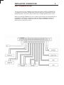
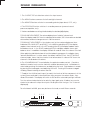
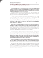
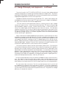
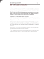
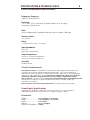
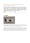
Stereo Preamplifier
05X
OPERATION MANUAL
T
E
C
H
N
O
L
O
G
I
E
S
I
N
C
.
CH SELECTOR
BALANCED COMPACT DISC TUNER
VIDEO
MONO
MONITOR PROCESSOR
VOLUME/BALANCE dB LEVEL
VOLUME/BALANCE
O5r LINE CONTROL BUFFER
MAIN LEFT RIGHT
SAFETY PRECAUTIONS
1
INTRODUCTION
2
INSTALLATION CONNECTIONS
3
DETAILED INSTALLATION
4
DESIGN PHILOSOPHY
5
SPECIFICATIONS & TECHNICAL DATA
6
CARE and HANDLING
7
WARRANTY & REGISTRATION
8
SAFETY PRECAUTIONS
1
CAUTION
WARNING
!
CAUTION: TO PREVENT ELECTRIC SHOCK,
DO NOT REMOVE COVER. NO USER
SERVICEABLE PARTS INSIDE, REFER
SERVICING TO QUALIFIED SERVICE
PERSONNEL.
THIS SYMBOL IS TO ALERT YOU OF THE
PRESENCE OF UNINSULATED DANGEROUS VOLTAGE WITHIN THE UNIT'S
ENCLOSURE THAT MAY BE OF SUFFICIENT MAGNITUDE TO CONSTITUTE A
RISK OF ELECTRIC SHOCK.
!
THIS SYMBOL IS INTENDED TO ALERT
YOU OF THE PRESENCE OF IMPORTANT
OPERATING AND MAINTENANCE
INSTRUCTIONS IN THE LITERATURE
ACCOMPANYING THE UNIT.
WARNING: TO PREVENT FIRE OR SHOCK HAZARD, DO NOT
EXPOSE THIS UNIT TO RAIN OR MOISTURE. TO
AVOID ELECTRICAL SHOCK, DO NOT OPEN THE
UNIT. REFER SERVICING TO QUALIFIED PERSONNEL.
CAUTION -
Never install or remove the power cord from the chassis
unless it has been disconnected from the AC power source
first.
Never pull on the power cord when removing it from an AC
power source. Grasp it by the plug.
Do not leave the power cord connected to an AC power
source unless it is connected to the unit.
It is recommend that during extended periods of nonuse
that the units power cord be unpluged from its AC power
source.
Route the AC power cord so that it will not be damaged or
walked on.
INTRODUCTION
2
III. Installation and Setup
This preamplifier is a precision device, designed in an effort to provide the listener
with unmatchedsound quality, design, and construction. In order tooperate your
preamplifier properly and to realize all of the capabilities of the 05X CONTROL
PREAMPLIFIER , we recommend that you read this entire manual carefully,
CH SELECTOR
BALANCED COMPACT DISC TUNER
VIDEO
MONO
MONITOR PROCESSOR
VOLUME/BALANCE dB LEVEL
VOLUME/BALANCE
O5r LINE CONTROL BUFFER
MAIN LEFT RIGHT
INSTALLATION CONNECTIONS
3
Basic Configuration & Setup
The first section of the installation instructions for the 05X CONTROL PREAMPLIFIER
is a diagram of the basic configuration required to bring the preamplifier into an
operating mode, These brief steps will allow you to begin operating your system.
Make sure during installation that the AC power connections are interrupted to the
preamplifier and all other components are off. While the diagram may be self
explanatory, we strongly recommend that you read the detailed instructions
following this introductory section.
DETAILED INSTALLATION
4
1. The CH SELECTOR set of buttons selects the input source.
2. The MONO button commons the left and right channels.
3. The MONITOR button switches in a recording device (tape deck, CD-R, etc.).
4. The PROCESSOR button switches in a audio processor (surround sound
processor,equalizer, ect.).
5. Volume and balance setting is indicated by the decibel (dB) display.
FOR VOLUME ADJUSTMENT: The volume display shows "relative" volume level.
When the display reads "99" there is no decibel attenuation, "00" is the maximum decibel
attenuation, andlevel changes occur in 1dB increments.
FOR BALANCE ADJUSTMENT: In the window next to the number display are three
iindicator LEDs, MAIN, LEFT, and RIGHT. In the MAIN mode (blue LED) the display
readout shows volume level. In the LEFT mode (white LED) the display readout shows
lleft balance level. In the RIGHT mode (red LED) the display readout shows right
balance level. In addition the display will flash on and off when the volume is muted.
When adjusting individual channel level for balancing purposes, the display shows
"actual" decibel level. In other words, the default value of "0" on the LEFT or RIGHT
channel mode, shows that the channel is not attenuated. A value of "99" shows the
channel is -99 db below full volume.
6. The VOLUME/BALANCE is controlled by the optical encoder control . Clockwise
rotation increases level, counter clockwise rotation decreases level. Left balance is
selected by pressing the knob once, and adjusting the level. Right balance is made
by pressing the knob again, and adjusting the level. Pressing the knob once again
will bring it back to being a volume control.
7. To adjust the GAIN of each input ( to match the levels of all the components in the
system), press and hold its selector button while you press the volume knob - then
release them both. The display will switch to "00" and the selected input light will flash.
Turn the volume knob clockwise to raise the input gain up to +18db or turn counter
clockwise to reduce the input level up to -99 db (note that the signs "-"or "+" are not
displayed).
To switch back to MAIN, press any button or the knob, or wait fifteen seconds.
1
2 3 4
5
6
CH SELECTOR
BALANCED COMPACT DISC TUNER
VIDEO
MONO
MONITOR PROCESSOR
VOLUME/BALANCE dB LEVEL
VOLUME/BALANCE
O5r LINE CONTROL BUFFER
MAIN LEFT RIGHT
DETAILED INSTALLATION
4
Remote Control Functions
The 05X Control Preamplifier may be operated by remote control. The Universal Remote
Osiris MX-350 Programmable Remote Control is included for maximum system flexibility with
your existing audio/video system. Please refer to the diagrams below for a detailed listing of
remote functions. The Osiris remote control manual should be consulted for all other nonCoda programming and use functions.
MAIN PAGE
REMOTE
PAGE KEYS
PRESS TO SELECT 05X CONTROL MODE
VOLUME
05X PAGE 1
05X PAGE 2
INPUT SELECT
REMOTE
PAGE KEYS
Balanced
MISC FUNCTIONS
Tape Monitor
Compact Disc
Processor Loop
Tuner
Mono
Video
BALANCE ADJUST
BALANCE ADJUST
DESIGN PHILOSOPHY
5
5.1 Design Philosophy and Approach
The circuity used in the FET CONTROL BUFFER 05x is the result of an advanced and
complete design process combining innovation and prove fundamentals. This process
avoids both the limitations of total adherence to convention and the flaws resulting from
inappropriate applications of clever circuit gimmicks.
Impedance isolation and matching is derived from FETs. While careful design can
yield good results from any device type, FETs consistently have the edge in voltage gain,
low noise, low interaction, and interface applications.
FETs are inherently transconductance devices, meaning that an input voltage
controls an output current. Unlike conventional transistors, FETs have extremely high
input impedance ( about 10 meg ohm - similar to vacuum tubes ). The FET
"senses" the audio signal without drawing current from the source. This eliminates
complex interactions with the source, allows maximum performance from each system
element, and greatly reduces the chance of cable characteristics altering the sound.
The absence of input current in FETs allows high bias currents for linearity and speed
without sacrificing DC parameters.
Noise is kept low by multiple paralleling of input devices, careful selection of circuit
impedances, and pre-screening of devices. The Class A complimentary followers used
to drive the preamp output are of such speed, linearity, and low output impedance that
no feedback correction is required or used. The advantage of this is that the circuit's
perfect stability and transient response are preserved into a wide range of difficult and
unpredictable loads. Variation in sound, which could occur through interactions with
interconnect cables and other system elements are thus avoided.
Until recently, perfect volume controls ( attenuators ) did not exist. This is because
conventional stereo potentiometers have serious channel mistracking ( 20% typically ),
become noisy with age, wear out, and have poor resolution of level - particularly when
operated by a motor as required for remote operation. In an attempt to solve these
problems, many manufacturers have been using "switched attenuators", which are
discrete, resistor ladders built on rotary switches. But while these eliminate channel
mistracking, they introduce new problems, including limited resolution, stepping transients,
and cannot be operated remotely. And they still wear out.
They limit resolution because the most contacts available on rotary switches are thirtyone. This requires two or three dB steps in order to get enough range out of the
attenuator, which isn't a fine enough resolution for most listeners. Switched attenuators
also introduce switching transients ( a "click" or "pop" ) each time the change positions.
This noise comes from two sources. The first is mechanical noise from the switch itself
as its ball-detent mechanism moves from detent to detent. But a more troublesome
source is the voltage difference caused by the change in the musical waveform during
the time it takes the switch to move from one position to the next. The greater the voltage
difference, the louder the transient.
DESIGN PHILOSOPHY
5
5.1 Design Philosophy and Approach - continued
The circuity used in the FET CONTROL BUFFER 05x is the result of an advanced and
complete design process combining innovation and prove fundamentals. This process
avoids both the limitations of total adherence to convention and the flaws resulting from
inappropriate applications of clever circuit gimmicks.
Impedance isolation and matching is derived from FETs. While careful design can
yield good results from any device type, FETs consistently have the edge in voltage gain,
low noise, low interaction, and interface applications.
FETs are inherently transconductance devices, meaning that an input voltage
controls an output current. Unlike conventional transistors, FETs have extremely high
input impedance ( about 10 meg ý - similar to vacuum tubes ). In other words, the FET
"senses" the audio signal without drawing current from the source. This eliminates
complex interactions with the source, allows maximum performance from each system
element, and greatly reduces the chance of cable characteristics altering the sound.
The absence of input current in FETs allows high bias currents for linearity and speed
without sacrificing DC parameters.
Noise is kept low by multiple paralleling of input devices, careful selection of circuit
impedances, and pre-screening of devices. The Class A complimentary followers used
to drive the preamp output are of such speed, linearity, and low output impedance that
no feedback correction is required or used. The advantage of this is that the circuit's
perfect stability and transient response are preserved into a wide range of difficult and
unpredictable loads. Variation in sound, which could occur through interactions with
interconnect cables and other system elements are thus avoided.
Until recently, perfect volume controls ( attenuators ) did not exist. This is because
conventional stereo potentiometers have serious channel mistracking ( 20% typically ),
become noisy with age, wear out, and have poor resolution of level - particularly when
operated by a motor as required for remote operation. In an attempt to solve these
problems, many manufacturers have been using "switched attenuators", which are
discrete, resistor ladders built on rotary switches. But while these eliminate channel
mistracking, they introduce new problems, including limited resolution, stepping transients,
and cannot be operated remotely. And they still wear out.
They limit resolution because the most contacts available on rotary switches are thirtyone. This requires two or three dB steps in order to get enough range out of the
attenuator, which isn't a fine enough resolution for most listeners. Switched attenuators
also introduce switching transients ( a "click" or "pop" ) each time the change positions.
This noise comes from two sources. The first is mechanical noise from the switch itself
as its ball-detent mechanism moves from detent to detent. But a more troublesome
source is the voltage difference caused by the change in the musical waveform during
the time it takes the switch to move from one position to the next. The greater the voltage
difference, the louder the transient.
DESIGN PHILOSOPHY
5
5.2 Parts Quality and Evaluation
1. Finishes - All exterior and interior metal parts are anodized. While paint may be more
impact resistant, the anodized surface is more resistant to solvents and prevents
corrosion. Moreover, the anodized parts' appearance can be enhanced by either
graining or bead-blasting the surface.
2. Circuit Board - Circuit boards are fiberglass epoxy with gold plating over a tin/nickel
barrier. This gold layer will not corrode, while the barrier plate prevents the gold from
migrating to the lower copper layer and detracting from its appearance.
3. Resistors - All are high reliability metal film 1% resistors.
4. Capacitors - All capacitors are of high quality. The only electrolytics used are in the
power supply where large numbers provide enormous filtering
capacitance for the
supply.
5. Semiconductors - There are no integrated circuits (IC) to be found in the circuit path.
Very high quality dual FETs are the only source of voltage gain and were selected for their
superb noise performance and precision matching. The remaining semiconductors are
also of very high quality, each possessing parameters ideally suited for the specific
application.
6. Connectors - Coda employs a standard RCA configuration with a gold plated case.
The balanced connectors are Neutriks from Switzerland.
7. Wire - All signal wire has been eliminated whenever possible. Where wire is used, Coda
employs silver plated copper, 141 strand, 18 guage wire with a silicone insulation.
SPECIFICATIONS & TECHNICAL DATA
6
Circuit Performance Specifications
Frequency Response:
-3db at 5 Hz and 200 kHz
-
Distortion:
< .01 % from 10 Hz to 40 kHz @ 5V peak into 600 Ohms or higher,
shunted by 1000 pF or less .
Gain:
Unity or independently variable on all inputs up to +18db in 1 db steps
Maximum Output:
10 Volts peak
Noise:
> 100 dBA referenced to 1 Volt output
Input Impedance:
20 k Ohms
balanced or unbalanced
Output Impedance:
50 Ohms non-reactive unbalanced
100 Ohms non-reactive balanced
Crosstalk:
90 dB @ 20 kHz
X Series Enhancements
Ultra High Class A Bias on Parralled FET Output Buffer - 500% Higher Bias level than 05r/e
Carefully selected and evaluated audiophile grade parts - rigorously tested by both
and objective methodologies by our development team. Parts used in critical signal path
and power supply applications include PRP & Holco Audio Resistors, Black Gate, Nichicon,
and RelCap capacitors, Fairchild Stealth fast recovery diodes, Vampire pure copper
RCA connectors. Includes the latest Burr-Brown PGA2320 SMA Digitally Controlled Attenuator,
offering the lowest distortion (.0004 THD) and interchannel crosstalk (-126db) spec
offered in such a device.
New microprocessor control and learning remote, offering increased functionality.
Power Supply Specifications
regulated with shielded toroidal transformer and 19,800 uf of low-ESR cpacitance
and bypassed Black Gate electrolytics smoothing the regulator outputs.
Dimensions
Height: . . . . . . . . .
Width: . . . . . . . . .
Depth: . . . . . . . . .
Weight: . . . . . . . . .
Power Consumption: .
1.75" Faceplate, 2.35" Overall
17.75" Faceplate, 17.0" Chassis
9.75" Overall
14.0 lbs. Shipping
10 Watts
CARE and HANDLING
7
The interior of the unit requires no special care, due to the use of sealed controls and
gold plating on contacts. If it becomes necessary to clean the exterior, a simple dusting
may be all that is required. If a cleaner is necessary, any dilute commercial ammonia
based product will be appropriate. NEVER use any abrasive rags, cleaners or chemical
solvents on the preamp.
When handling the unit, take care not to mar the aluminum. Aluminum is a medium
hardness metal and can be scratched by the harder tool steels.
Avoid exposing the unit to direct sunlight, and keep it away from sources of intense
heat.
Do not throw away the carton or associated packing material. They are ideal if you
need to pack the unit for moving, and in the unlikely event that servicing is needed, they
will be necessary for safe shipment.
Be sure to provide adequate insurance when shipping.
WARRANTY
I. Warranty- Any failure of Coda products to operate or to meet specifications,
applicable at time of manufacture, due to a manufacturing defect or component
failure, will be corrected by Coda Technologies, Inc. without charge for parts, or labor
for a period of ten years from date of original purchase. Coda Technologies, Inc. will
provide for surface transportation to the Coda factory from an authorized Coda
Technologies, Inc. authorized dealer for a period of one year from date of purchase.
Maximum term for any warranty claim shall be ten years from date of original sale, or
11 years from date of manuafacture, whichever is shorter. Date of manufacture shall
only be defined only manufacture date imbedded in serial number of product.
Warranty shall be transferrable for a period of five years from the date of purchase.
Subsequent owners are required to provide proof of sale/transfer from the original
owner. Original owner may transfer warranty for the entire period of the warranty.
Coda Technologies reserves the right to make the final determination as to validity
of warranty claims in cases where ownership or manufacture date is not clear and
substaniated in writing.
II. Procedure- If the product should require service under warranty, take it with proof
of purchase date, with its carton and packing material, to a Coda Technologies, Inc.
dealer. The dealer will arrange for service. Direct shipments to the factory will be
not be accepted without advance written authorization (RMA). Coda products
purchased outside of the U.S. will be covered by those warranty conditions extended by
the importing distributor which may differ in some respects from those given above.
Warranty service, if required, is the responsibility of the importing distributor. If a Coda
Technologies, Inc. product is removed from the country of original purchase, Coda
Technologies, Inc. distributors or dealers are not obligated by the conditions of this
warranty and repairs will be affected at their discretion.
III. Exclusion of Coverage- At the sole opinion of Coda Technologies, Inc. the following
situations are specifically excluded from coverage:
1.
Any product not operated in accordance with the instructions contained in this
manual, or otherwise subjected to abuse, tampering, modification, accidental damage,
or serial number defacement.
2. Damage to other property caused by any defects in this product, damages based
upon inconvenience, loss of use of the product, loss of time, commercial loss, or any other
damage whether incidental, consequential, or otherwise.
3. It is Coda Technologies, Inc. policy to extend coverage when reasonable doubt exist;
however, freight and diagnostic charges will be billed for any units returned under
warranty and found by the company to be operating according to specification.
This warranty gives you specific legal rights, and you may also have other rights which
vary from state to state.
Coda Technologies, Inc. continually researches new techniques, designs, and construction
methods and so reserves the right to introduce refinements into current product lines
without notice or obligation. The company may offer product modifications to make
these refinements available to earlier production units.
WARRANTY REGISTRATION
Fill in and retain this copy of the warranty registration sheet for your records .
To validate your registration, please call, mail, email, or FAX a copy of this registration
to Coda at 916.386.8296 within 30 days of date of purchase. Please include proof of
purchase with your submission.
MODEL DESIGNATION:__________________________________
SERIAL NUMBER:______________________________________
DATE OF PURCHASE:
PLACE OF PURCHASE
Dealer:___________________________________________
Address:__________________________________________
City:_____________________ State:____ Zip:__________
Phone:____________________________________________
PURCHASER
Name:_____________________________________________
Address:__________________________________________
City:_____________________ State:____ Zip:__________
Phone:____________________________________________
NOTES:
7850 CUCAMONGA AVENUE #34
SACRAMENTO, CA 95826 USA
T
E
C
H
N
O
L
O
G
I
E
S
I
N
C
.
phone +01 916.383.3653 fax +01 916.455.3653
on the web at CODA.CC
email us at [email protected]