1
TECHNICAL DATA
PACKAGE
TDP3504 IOIN 9300-3504-00
Third Edition ISeptember 1989
Rack Mount Speaker
User Station
O/N 9000-2727-00
TW INTERCOM SYSTEM
RTS SYSTEMS
A Telex Communications Company
1100 West Chestnut Street 1 Burbank, California 91506 I Phone 8181566-6700 / FSCM: 60572
TECHNICAL DATA PACKAGE
Model RMS300 TW Intercom System Rack Mount Speaker User Station
PROPRIETARY NOTICE
UNPACKING INFORMATION AND INSPECTION
The information and design disclosed herein were
originated by and are the property of RTS Systems.
RTS Systems reserves all patent, proprietary design,
manufacturing, reproduction, use and sales rights
thereto, and to any article disclosed therein, except to
the extent rights are expressly granted to others.
Immediately upon receipt of the equipment, inspect
the shipping container and the contents carefully for
any discrepancies or damage. Should there be any,
notify the freight company and the dealer at once.
The shipping Model RMS300 container should
contain the following components:
COPYRIGHT NOTICE
Ordering Number 9000-2727-00
Copyright 1988 by RTS Systems, Burbank, California,
USA. All rights reserved. Reproduction in whole or
in part without prior written permission from RTS
Systems is prohibited.
QQ
RTS Systems
Part Number
Description
PATENT NOTICE
1
1
9010-2727-00
9300-3504-00
Model RMS300
Technical Data Package
The Model RMS300 contains and uses a design
embodied in United States Patent No. 4,358,644:
"BILATERAL CURRENT SOURCE FOR A
MULTI-TERMINAL INTERCOM". This design
employs a bilateral current source operated as a twowire to four-wire converter.
NOTE: Detailed information concerning Theory of
Operation, Maintenance, Spare Parts and System
Interconnection is available in "The TW Intercom
System Technical Manual", which may be obtained
through an RTS Systems Dealer or directly from
through RTS Systems.
TECHNICAL DATA PACKAGE, TDP 3504
Model RMS300 TW Intercom System Rack Mount
Speaker User Station
Printing History:
First Edition:
Second Edition:
Third Edition:
.................... ....
...........
...............................................n r
.........................iii
Description & Specifications ............1-1
Installation ..............................oemoa.2-l
Operating Instructions ...................-3-1
Drawings ..........................
.
.. . 4 - 1
Unpacking Information
Quick Table Of Contents
Warranty
Shipping Information
September 1983
October 1988
September 1989
Published by the Engineering Department of RTS
Systems, which is responsible for its contents.
Written by:
Stan Hubler
Lianne Sterling Swanson
Edited by:
Sheryl Thompson
QUICK TABLE OF CONTENTS
O.Oe~l
ooeeea.eo.e~~
Address all communication regarding this publication
to:
Director of Engineering
RTS Systems
1100 West Chestnut Street
Burbank, CA 91506 U.S.A.
RTS Systems, Burbank, CA 91506 / FSCM: 60572 TDP3504 / Thirdd Edition, Sept. 1989
Page ii
.*
TECHNICAL DATA PACKAGE
Model ~ ~ ~ TW
3 Intercom
0 0 System Rack Mount Speaker User Station
RTS SYSTEMS' LIMITED WARRANTY
RETURN SHIPPING INSTRUCTIONS
The products of RTS Systems are warranted to be
free from defects in materials and workmanship for
a period of one year from the date of sale.
Procedure For Returns:
RTS Systems sole obligation during the warranty
period is to provide, without charge, parts and
labor necessary to remedy covered defects
appearing in products returned prepaid to RTS
Systems, 1100 W. Chestnut Street, Burbank,
California, 91506, U.S.A.. This warranty does not
cover any defect, malfunction or failure caused
beyond the control of RTS Systems, including
unreasonable or negligent operation, abuse,
accident, failure to follow instructions in the
Technical Manual or the Owner's Manual,
defective or improper associated equipment,
attempts at modification and repair not authorized
by RTS Systems and shipping damage. Products
with their serial numbers removed or effaced are
not covered by this warranty.
To obtain warranty service, follow the procedures
entitled "PROCEDURE FOR RETURNS" and
"SHIPPING TO MANUFACTURER FOR
REPAIR OR ADJUSTMENT" listed below.
This warranty is the sole and exclusive express warranty given with respect to RTS Systems products.
It is the responsibility of the user to determine
before purchase that this product is suitable for the
user's intended purpose.
ANY AND ALL IMPLIED WARRANTIES,
INCLUDING THE IMPLIED WARRANTY OF
MERCHANTABILITY ARE LIMITED TO THE
DURATION OF THIS EXPRESS LIMITED
WARRANTY.
NEITHER RTS SYSTEMS NOR THE DEALER
WHO SELLS RTS SYSTEMS' PRODUCTS IS
LIABLE FOR INCIDENTAL OR
CONSEQUENTIAL DAMAGES OF ANY KIND.
If a repair is necessary, contact the dealer where
this unit was purchased.
If repair through the dealer is not possible, phone
the RTS Systems Customer Service Department,
located at the factory, as directed below. They will
issue a Return Authorization Number.
DO NOT RETURN ANY EOUIPMENT TO THE
FACTORY WITHOUT FIRST OBTAINING A
RETURN AUTHORIZATION NUMBER.
Be prepared to provide your company name,
address, phone number, a person to contact
regarding the repair, the type and quantity of
equipment, a description of the problem and the
serial number(s).
Questions regarding returns for repair should be
directed to:
Customer Service
RTS Systems
1100 W. Chestnut St.
Burbank CA 91506 USA
Telephone: (818) 566-6700
Telex:
194855
Telefax:
(818) 843-7953
SHIPPING TO MANUFACTURER FOR REPAIR
OR ADJUSTMENT
All shipments of RTS Systems equipment should
be prevaid via United Parcel Service or the best
available shipper. The equipment should be
shipped in the original packing carton; if that is not
available, use any suitable container that is rigid
and of adequate size. If a substitute container is
used, the equipment should be wrapped in paper
and surrounded with at least four inches of excelsior or similar shock-absorbing material. All
shipments should be directed to the attention of the
Order Service Department and must include the
Return Authorization Number.
Upon completion of any repair the equipment will
be returned collect via United Parcel Service or
specified shipper.
RTS Systems, Burbank, CA 91506 / FSCM: 60572 TDP3504 / Third Edition, Sept. 1989
Page iii
TECHNICAL DATA PACKAGE
Model RMS300 TW Intercom System Rack Mount Speaker User Station
I
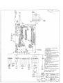
?W SYSTEM POWER SUPPLY
I
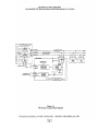
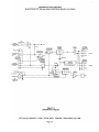
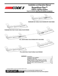
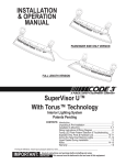
Figure 1-1
TW System Concept Block Diagram
RTS Systems, Burbank, CA 91506 / FSCM: 60572 TDP3504 / Third Edition, Sept. 1989
Page iv
TECHNICAL DATA PACKAGE
Model RMS3OO TW Intercom System Rack Mount Speaker User Station
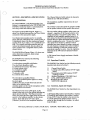
SECTION 1: DESCRIPTION & SPECIFICATIONS
The Channel Selector Switch selects the channel on
which the user will talk and listen.
1.1 DESCRIPTION
The Model RMS300, a Rack Mount Speaker User
Station, is a component used in the TW INTERCOM
SYSTEM. Each User Station is a communications
unit along a multi-unit conference bus.
The System Concept Block Diagram, Figure 1-1,
shows User Station interconnection, and User Station
connection to the system power supply.
User Station interconnection can be: 1) centrally
wired, with each cable coming from a central point, or
2) distributed, where all the user stations are looped
together from one to another, or 3) a combination of
both. The centrally wired interconnection not only
reduces interchannel crosstalk, but also allows for
easier expansion into an assignable channel, multichannel system.
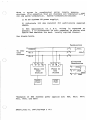
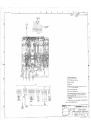
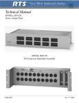
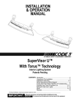
The RMS3OO Block Diagram, Figure 1-2, shows user
station functional components, input/output
connections, and controls.
The RMS3OO User Station has the following
functional components:
The headphone amplifier output drives the user's
headphones.
The Volume Control also feeds the speaker amplifier
via the speaker switch and the speaker dm network.
The user station voltage regulator takes power from
channel 1,regardless of the channel selector switch
setting (exception: local power option units). The
regulator not only supplies regulated power to the
user station, but also prevents unwanted interaction
between the user station and theat intercom line
which is supplying the power. Because the regulator
takes power from channel 1,channel 2 can be
expanded into many channels by using a switch and,
for each channel, a separate wire and a termination
network consisting of a 200 ohm resistor and a 10
microfarad capacitor in series. (See the Application
Diagrams in the TW Intercom Systems Technical
Manual).
A TW System Power Supply terminates a line with
200 ohms.
1.1.2 Operational Controls
1) a microphone preamplifier with limiter
2) an electronic microphone switch
3) a "bilateral current source" line driver
4) a listen volume control
5) a headphone amplifier
6) a speaker amplifier
7) a speaker switch
8) a channel selector switch
The RMS300 User Station has the following controls,
described and shown in Section 3:
1)
2)
3)
The microphone preamplifier/limiter
converts the small microphone signal to a strong
line level signal
conditions the signal strength from loud and soft
talkers to be almost the same
sends the signal to the line via the microphone switch
and a "bilateralcurrent source".
The bilateral current source adds signal, via the
channel select switch, to the line without affecting any
signals already on the line. The bilateral current
source also extracts the listen signal from the line and
sends it to the headphone amplifier via the volume
control. Some of the user's own voice signal
("sidetone") is also fed to the headphone amplifier.
4)
5)
6)
7)
Channel Select Switch
Latching-action MICrophone ON-OFF toggle
switch.
Momentary-action MICrophone ON-OFF
pushbutton switch.
SpeakerlHeadphone VOLUME Control
CALL LIGHT switch/indicator
SPeaKeR ON/OFF switch
SIDETONE Adjustment
1.13 Connection, Inputs and Outputs
The RMS300 User Station has four input/output connectors:
1) DYNamic MICrophone type HeaDSeT or handset
2) CARBON MICrophone type headset or handset
3) Line INPUT (ties the station to the intercom line
4) LOOP/EXTension (allows another station to
access the line through the first station. Also called
loop-through.)
RTS Systems, Burbank, CA 91506 / FSCM: 60572 TDP3504 / Third Edition, Sept. 1989
Page 1-1
TECHNICAL DATA PACKAGE
Model RMS300 TW Intercom System Rack Mount Speaker User Station
LINE IN
LINEIEX1
Figure 1-2
RMS300 Block Diagram
RTS Systems, Burbank, CA 91506 / FSCM: 60572 TDP3504 / Third Edition, Sept. 1989
Page 1-2
TECHNICAL DATA PACKAGE
Model RMS300 TW Intercom System Rack Mount Speaker User Station
1.2 MODEL RMS300 SPECIFICATIONS
OVERALL SYSTEM SPECIFICATIONS
Audio Line Voltage, Nominal
1volt, peak (0 dBm voltage-equivalent)
Average Speech Level Range
-20 dBV to -10 dBV
Absolute Maximum Speech Level
3 volts, peak (linear limit)
Audio Line Impedance, Nominal
200 50 ohms, 75 Hz to 20kHz
System will continue to operate from 50 ohms to 300 ohms
System DC Line Voltage
Nominal
Operational Range
Steady state without damage
Transient
32 volts DC
18 to 35 volts DC
-1.5 volts to 36 volts DC
200 volts, 8 milliseconds or less (after this time, power supply and
user station fuses will open)
System DC Current
Quiescent (per station)
Dynamic (per station)
10 to 40 milliamps
50 milliamps (w/25 ohm headphones)
70 milliamps (w/25 ohm headphones and lights)
100 milliamps (w/8 ohm speaker)
Start-Up Current
1.25 amperes, 50 units, all kinds
~ a u lCurrent
t
4.0 amperes, power supply at voltage > 12 volts
1.0 amperes, power supply at voltage < 12 volts
Operating Distances
Maximum DC limit
5,000 ft. distance along cable, power supply to single station #22
gauge wire -DC voltage drop limitation
Maximum AC limit
10,000 ft. dry pair, power supply at each end, #22 gauge wire
System Capacitance
0.3 microfarads (cumulative effect of 10,000 ft. of Maximum cable at
30 picofarads/foot)
RTS Systems, Burbank, CA 91506 / FSCM: 60572 TDP3504 / Third Edition, Sept. 1989
Page 1-3
TECHNICAL, DATA PACKAGE
Model RMS300 TW Intercom System Rack Mount Speaker User Station
USER STATION SPECIFICATIONS
Input DC voltage:
20 to 35 volts DC, operating from -200 to +36 volts DC without
damage
DC Current
Quiescent, 10 to 40 milliamps
50 milliamps, typical (w/25 ohm headphones)
75 milliamps, typicall (w/25 ohm headphones + light)
100 milliamps, typical(w/8 ohm speaker
Impedance across line:
10,000 ohms typical;
Ambient Temperature Range
Operating: 0 C to 60 6
Storage: -55 C to 125 6
Noise contribution
to 200 ohm line:
One Unit: -75 dBu
Ten Unit: -67 dBu
ohms worst case dynamic operation
Microphone Preamplifier
Input impedance*
Source Impedance*
Maximum Input Level*
Voltage gain:
Frequency Response
Limiter range
Carbon Mic Excitation Current
470 ohms
200 ohms, nominal
150 millivolts
54 dB
100 Hz to 10,000 Hz, 3dB
50 dB
10 milliamps, nominal
"Dynamic Microphone Input
Current Source
Transfer ratio:
Output:
5 milliamps/l.5 volts
5 milliamps into 200 ohms
Headphone Amplifier
Overall voltage gain
Overall voltage gain
Output power:
Frequency Response
Headphone Impedance Range
Sidetone Adjustment Range
24 dB
9 volts peak-to-peak into 25 ohms
Headset station: 112 watt into 25 ohms
Speaker Station: 2 watts into 8 ohms
150 Hz to 8,000 Hz, 3 dB
25 to 600 ohms
20 dB to full on
Call Light:
Signaling Frequency
Flashing Rate
Dimensions
3.468" H x 1.5" W x 3.0 D
13.21 x 3.81 x 7.62 centimeters
20,000 kHz 3 dB
5Hz 2Hz
RTS Systems, Burbank, CA 91506 / FSCM: 60572 TDP3504 / Third Edition, Sept. 1989
Page 1-4
TECHNICAL DATA PACKAGE
Model RMS3OO TW Intercom System Rack Mount Speaker User Station
r1
2 2 ELECTRICAL
SECTION 2: INSTALLATION
22.1 Power
2.1 MECHANICAL INSTALLATION
The RMS300 receives electrical power from either:
The Model RMS300 mounts in an EIA standard 19inch equipment rack/enclosure, and is one rack unit
high. Allow a minimum of 4 inches (101.6 mm) for
the panel microphone and controls in front.
Additional depth should be allowed for the cabling in
the rear. There are no ventilation requirements.
(1) a system power supply (26 to 32 volts DC on line
connector pins 2 (+) and 1 (com) (1 or two channel
operation); or
(2) a local power supply option (14 to 26 volts DC).
A user station requires 18 to 33 volts to be a 10,000
ohm bridging impedance across the powering line, but
the station can otherwise operate (as in the local
power option) from 12 to 33 volts.
2.1.1 Headset Requirements
Dynamic microphone headset type:
50 to 1000 ohm microphone
25 to 1000 ohm headphone(s)
i\\d
High efficiency headphones are recommended because less line current is required from the power
supply. Use headphones with an impedance of 25
ohms or greater. Low impedance 8 ohm headphones
are not recommended. Headphones with good
acoustic isolation (20 to 40dB) improve communication in high ambient noise environments, and allow
the user to use the headphones at a less tiring, lower
volume.
In the headset connecting cable, prevent coupling
between the microphone and headphone leads by using a shielded, twisted pair for the microphone, and a
separate, twisted pair for the headphones. Do not
allow headphone ground to contact microphone
ground or shield. Tie the shield to microphone
ground or "mic low". The headset cable can be made
longer when the microphone and headphone pairs are
physically separated. The wider the separation, the
longer the cable length which may be used. Estimated maximum usable headphone cable lengths are
as follows:
When using a local power supply option, each channel
requires a 200 ohm load. See Figure 1-1. It is
necessary to do this only once for each channel string.
Model RMS300 current requirements range from 30
to 100 mA, Since, in (I), above, the power and
communications signals may share conductors, it may
be necessary to overcome power losses by increasing
conductor size over long runs (over 1/2 mile (804
m)). Typical operating distance for one RMS300
station is 1/2 mile (.80 km), and for one RMS300-L,
1/3 mile (0.53 km) using a normal # 22 AWG
conductor size.
22.2 Signal
The required number of conductors to interconnect
user stations is as follows (For standard unbalanced
TW user stations):
# of Channels
# of Conductors
Single cable,
Two shielded twisted pair:
10 ft. (3 m).
*
Using a TW power supply (and possibly
operating on a TW system).
Dual ribbed cable,
Two shielded twisted pair:
30 ft. (9 m).
**
Using a non-TW power supply.
*** Using a TW power supply and operating on a
TW two channel system.
RTS.Systems, Burbank, CA 91506 / FSCM: 60572 TDP3504 / Third Edition, Sept. 1989
Page 2-1
TECHNICAL DATA PACKAGE
Model RMS300 TW Intercom System Rack Mount Speaker User Station
Use shielded cable to interconnect user stations in areas of possible electrical interference, (areas such as
those near: digital equipment, high current primary
power conductors ("mains"), transformers, transmitters, and lamp dimmers).
cable connectors are lifted out of the mud or snow
and protected with plastic bags. Water, mud and
snow in connectors can cause considerable audible
noise.
2.2.5 Hlam Prevention
Most two channel applications may use either standard microphone cable (for convenience) or twotwisted-pair cable (considerably less expensive than
microphone cable). Standard wire size for the TW
Intercom System is #22 gauge wire for interconnection. For permanent installations it is recommended
that each channel should have individually shielded
twisted pair of at least #22 gauge wire, such as
Belden #8723 for 2 channels. Connect the shield to
system common but do not tie the shield to chassis,
earth or connector shell ground.
2 2 3 Crosstalk Control
In the TW Intercom System all channels share a
common circuit ground return. Crosstalk due to
common ground resistance can be lowered by reducing the common ground resistance. Reduction of
ground resistance can occur as a side benefit of using
shielded cable, since the shield drains can be tied together and electrically parallel the circuit ground.
Another way of lowering resistive crosstalk is to
"homerun" all interconnecting cables to a central or
"home" location. In this configuration, the ground
path is short and the corresponding ground resistance
is small. Crosstalk due to mutual capacitance occurs
when the signal on one wire of a twisted pair couples
into the other wire. Separating the two conductors
with a shield greatly reduces the capacitive crosstalk.
To reduce both capacitive and resistive crosstalk and
to afford a degree of R F and electrostatic shielding,
use a cable which has a shielded twisted pair for each
channel. Each pair consists of a conductor for the
channel, a conductor for circuit ground return and a
shield around the two conductors. The shield is accessed via a drain conductor. This drain conductor
and the shield can augment the circuit grounds and
thus lower the ground resistance.
Routing the TW Intercom System cables along the
same ductways and pathways as power cabling can increase the noise and hum levels.
Prevent inducing hum into the system by not locating
user stations near hum sources such as power
transformers, electrical switch panels, lamp dimmers
or TV cameras. When the microphone switch is
turned on, the dynamic microphone acts as a sensitive
antenna for hum sources.
2.4 USER STATION CONNECTIONS
Dynamic Microphone headset connector:
XLR-4-31 type receptacle (Jl)
Input level: -55 dbu nominal
Output Ievel to headphone: 10 volts peak-to-peak
open circuit.
Pin 1- Microphone low
Pin 2 - Microphone high
Pin 3 - Headphone low
Pin 4 - Headphone high
Carbon Microphone headset connector: Standard
114" Phone Jack (52)
Input level: -15 dbu nominal
Output to Headphone: 10 volts peak-to-peak open
circuit.
Tip - Carbon Microphone
Ring - Headphone
Sleeve - Common/ground
Line input connectors: (53154)
XLR-3-31/32 types (for two-channels)
Pin 1- Common (low side of line)
Pin 2 - Channel 1
Pin 3 - Channel 2
XLR-4-31/32 types (for three-Channels)
22.4 Moisture / Contamination Protection
When using equipment in the rain, always protect the
equipment with plastic covers----also, make sure all
Pin 1- Channel 1
Pin 2 - Channel 2
Pin 3 - Channel 3
Pin 4 - Common (low side of lime)
RTS Systems, Burbank, CA 91506 / FSCM: 60572 TDP3504 / Third Edition, Sept. 1989
Page 2-2
TECHNICAL DATA PACKAGE
Model RMS300 TW Intercom System Rack Mount Speaker User Station
This page intentionally blank
RTS Systems, Burbank, CA 91506 / FSCM: 60572 TDP3504 / ~ h i r dEdition, Sept. 1989
Page 2-3
TECHNICAL DATA PACKAGE
Model RMS300 TW Intercom System Rack Mount Speaker User Station
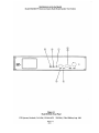
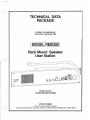
Figure 3-1
Model RMS'3OO Front Panel
RTS Systems, Burbank, CA 91506 / FSCM: 60572 TDP3504 / Third Edition, Sept. 1989
Page 2-4
TECHNICAL DATA PACKAGE
Model RMS300 TW Intercom System Rack Mount Speaker User Station
SECTION 3: OPERATION
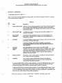
3.1 Operating Controls (See Figure 3-1)
Table 3-1 below lists the Model RMS300 operating controls. The reference numbers in Table 3-1correspond
to the circled numbers in Figure 3-1.
Table 3-1
Ref.
No.
-
Name
Descrivtion
1
Channel Select Switch
Selects one of two channels (standard) or one of three channels (optional).
The Call Light Option transmitter and receiver operate on the channel
selected by this switch. The CHannel Select Switch is omitted in the Single
Channel (SC) option.
2
MIC ON-OFF Toggle
A latching-action switch. Turning on the microphone slightly "dims" or
attenuates the speaker.
3
MIC ON-OFF
Pushbutton
A momentary-action pushbutton switch. Not standard with the Call
VOLUME
A speakerlheadphone volume control. May be a dual control for the Dual
Listen (DL) or Program (E) Option.
4
f\
Light Option. Turning on the microphone here also slightly "dims" or
attenuates the speaker.
CAUTION: ALWAYS TURN THIS CONTROL ALL THE WAY
COUNTERCLOCKWISE (TO THE LEFT) BEFORE PLUGGING IN
THE HEADSET.
Call Light
Indicator
Switch
This switch/indicator appears in place of the MIC ON-OFF
PUSHBUTTON (#3) on user stations with the "CallLight" option. When
depressed, this switch adds a 20 kilohertz signal to the TW intercom line
on the same channel that the CHannel Select Switch has been set. This
signal activates the Call Light receiver on all user stations which are
switched to the same channel.
SPeaKeR ON/OFF
This switch: 1) turns on the speaker, 2) disables the headset microphone
and 3) enables the panel microphone.
SIDETONE
The screwdriver-adjusted SIDETONE control sets the "sidetone"
level during headset operation and sets the "balance"nulling during
speakerlpanel microphone operation.
To adjust the SIDETONE control for speaker operation: 1) turn ON the SPeaKeR switch, 2) turn
ON the MICrophone switch, 3) set the VOLUME control to about 50%, 4) hum into the panel
microphone and adjust SIDETONE for minimum sound through the loudspeaker.
To adjust the SIDETONE control for headset operation: 1) turn OFF the SPeaKeR switch, 2) turn
ON the MICrophoone switch, and 3) plug in a headset, 4) set the VOLUME control to about 50%,
5) turn the SIDETONE control fully counterclockwise, the adjust it clockwise for a comfortable level
of your own voice while talking into the headset microphone.
RTS Systems, Burbank, CA 91506 / FSCM: 60572 TDP3504 / Third Edition, Sept. 1989
Page 3-1
Installation. Local Power Option. RMS300 and SPK308
The RMS300 and SPK300 can be powered from an external (local)
powes supply of between 18 to 33 volts DC,
The local power
option, a s supplied by RTS Systems uses a power supply assembly
(RTS #9020-4425-OO), which is 117 VAC 60 Hz in, 24 VBC 400mA
out
To modify the RMS300 or SPK300 for local power operation:
1.
Remove diode D26 from the CC3QO P. (2. beard.
2.
Add J6, 4 pin jack (Calrad #38-454, RTS #2013-0005-001,
to the back panel. Wire as shown in the diagram below.
Pin 1= common, Pin 2= external supply + (18 to 33 VDC).
3.
Wire P6, 4 pin plug (Calrad #30-453, RTS #2013-0016-00)
to the external supply: Pin 1- common, Pin 2= external
supply 9. Plug P6 into J6 on the RMS300 or SPK300 back
panel,
Note:
If using RTS local power option kit
9002-5541-00, the external supply will already be wired
to P6.
Local. Power
(Back Panel)
#22 AWG Wire
0
0
0
0
0
0
0
'
+12
Remove ~26CC300 P - C - Board
8
9
10
When a system is constructed using locally powered user
stations, it is essential that all channels are terminated with a
200 ohm system termination. System terminations include:
1) An RTS Systems TW power supply*,
2) A discrete 200 ohm resistor for each locally supplied
channel,
3) When application of a B.C.
voltage is expected or
possible, a 10 microfarad/ 50 volt capacitor in series with
the 280 ohm resistor for each locally supplied channel.
See diagram below.
Termination
To other
user
stations
A 1ternate
Termination
Phase %%I
I
Power.
Phase 11%
m
I
Power
*Examples of RTS Systems power supplies are: PS8, PS10, PS30,
PS31, PS50, and PS60.
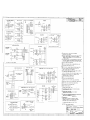
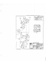
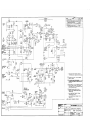
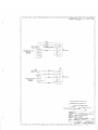
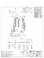
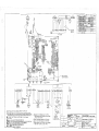
TECHNICAL DATA PACKAGE
Model RMS300 TW Intercom System Rack Mount Speaker User Station
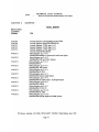
SECTION 4:
DRAWINGS
RTS Svstems
Document
Number
Servicing Diagram, Light Signaling Circuit CC285
Servicing Diagram, Model RMS3001SPK300
Schematic Diagram, CC300, page 1 of 3
Schematic Diagram, CC300, page 2 of 3
Schematic Diagram, CC300, page 3 of 3
Wiring for External Microphones
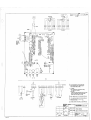
Wiring Diagram, pg. 1of 11
SPICJRMS300Standard -L Option and Local Power Option
Wiring Diagram, pg. 2 of 11
SPKJRMS300 3CH and 3CH-L Options
Wiring Diagram, pg. 3 of 11
SPK/RMS300-DL
Wiring Diagram, pg. 4 of 11
SPKJRMS300, IFB Option
Wiring Diagram, pg. 5 of 11
SPICJRMS3OO-DL-3CH
Wiring Diagram, pg. 6 of 11
SPKJRMS300 Program Input Option
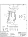
Wiring Diagram, pg. 7 of 11
SPKJRMS300 DL (Dual Listen) - E (Program Input)
Wiring Diagram, pg. 8 of 11
SPICJRMS300-USM-B
Wiring Diagram, pg. 9 of 11
SPKJRMS300-VI-3CH-VI
Wiring Diagram, pg. 10 of 11
SPKJRMS300-DL-MSG
Wiring Diagram, pg. 11 of 11
SPKBMS300 Program Input and USMB Options
RTS Systems, Burbank, CA 91506 / HCM: 60572 TDP3504 / Third Edition, Sept. 1989
Page 4- 1
FROM CHANNEL
SELECT S W I T C H
(CH.l)
,I
.
8
E
I
DL-VI
:
OPTION
NOTE:
NOT FOR USE W I T H D L OPTION
L_-________________-----------------------
CH.1 H I
CH.1 L O
CH.2 H I
CH.2 L O
C H A S S I S GND
O
FROM CHANNEL
SELECT S W I T C H
(CH.2)
2 6 I N U N I T S W I T H C A L L L I G H T OPTIONS (-L).
- M I C S W I T C H I S NOT INSTALLED.
MOMENTARY
II
II
O
2 5 FOR 3CH-DL OPTION: REMOVE W2 WHEN AUX. L I S T E N I S S E T TO MONITOR
CHANNEL 1. REMOVE W 4 WHEN AUX. L I S T E N I S S E T TO MONITOR
CHANNEL 2. CUT TRACE BETWEEN U4-3 & L 3 WHEN AUX. L I S T E N I S SET
T O MONITOR CHANNEL 3.
USM
O
-
2 4 I N U N I T S B U I L T PRIOR TO 1-3-88.
THE CARBON M I C WAS A C T I V E I N BOTH
T H E "PANEL" & "HEADSET" S W I T C H POSITIONS. I N U N I T S B U I L T AFTER
3-1-88.
T H E CARBON M I C I S A C T I V E ONLY I N T H E "HEADSET" P O S I T I O N .
NOTE:
UNIT
MUST
B E LOCAL POWERED
-- ,--
600:600
FOR
LOCAL POWER
CUT
TRACE
FOR
SQUAWK
CUT
TRACE
OPTION.
REMOVE
FOR SQUAWK OPTION.
OPTION.
FOR E
026.
ADD JUMPER
CHANGE
R99 T O 10K.
(BALANCED
PROGRAM I N )
BETWEEN SQ1 & SQ2.
OPTION.
SQUAWK
OPTION.
ON 3-CH (3-CHANNEL)
OPTIONS. SEE D E T A I L FOR P I N OUT OF
CONNECTORS.
I N P U T (J3) AND LOOP/EXT (J4)
O
18 FOR E (BALANCED
T O JMPE. D E L E T E
1 7 . FOR D L - V I
PROGRAM IN). SQUAWK OPTIONS:
JUMPER FROM J M P l TO JMPP.
O P T I O N (DUAL
L I S T E N W I T H VIDEO
JMP2
ISO).
JUMPER
ALTERNATE P I N OUT NOTED FOR 7 3 0 7 I.C. (APPLIES
MANUFACTURED P R I O R T O JANUARY. 1984).
D E L E T E P 2 FOR 2-WIRE
CUT
C47
FOOT
SWITCH OPTION
J7
p7 CALRAD
:
:
(REF)
;;
J2
P2
(REF) (REF)
IF,
;:
CHANNEL
SELECT
SWITCH
(FS)
I N
I F B OUT
130-456
LICON
05-135
SWlP3T C H . ~
i
/
O
-
TO 2 2 K
REMOVE FOR
DL (DUAL
CUT
FOR D L (DUAL
I
I
l OCAl
CALRAD
J 6
130-454
POWER
P6
CALRAD
(LP)
:
-VI
! :
OPTION
OPTION
(UNITS WITHOUT
D L OPTION)
j
j
i
TO USM
:-------------------------------------------------------------:----------------------------------------J
I
WHEN
:
I
7
THESE PARTS ARE ALTERNATE B I A S NETWORK FOR ALTERNATE
CONDENSER MIC. REMOVE R 3 & C1 WHEN U S I N G T H I S NETWORK.
ARE
6
1
II
& U10 ARE NOT USED.
I S JUMPERED TO
3
RESISTORS
ARE
&
SHOWN MICROFARADS/VOLTS.
UNLESS
CARBON F I L M .
RTS
I
4
I
3
I
+/-5%.
II
.
ISIZE
2
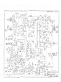
SYSTEMS
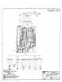
SCHEMATIC DIAGRAM
SPK-300
RMS-300
I
5
WATT.
NO.
300
Drawn
R.NFILSON
Checked
i
1/4
OTHERWISE S P E C I F I E D
Issued
I
SHOWN B Y
U 3 I S I N S T A L L E D (DL.E.
D
8
REMOVED.
R31-CHANGE
T O 10K
SQUAWK OPTIONS).
CONTROL
PANELS
!
R15
4
N 0 T ES:
NO CONNECTION
+.
!
N30-453
S4
(CHANNEL S E L E C T
SWITCH)
OPTIONS.
OPTION.
I N T H E STANDARD C O N F I G U R A T I O N U3.U4.U5,U7.U8
U 3 P I N S 5.6 dc 7 ARE JUMPERED TOGETHER. JMPl
JMP2. AND B l I S JUMPERED T O PI.
1. A L L
SUPPLY
OPTION.
R33.
SHOWN
CONTRACT
TO L P
SQUAWK
OPTION.
LISTEN)
LISTEN)
SPK U N I T S HAVE T 5 INSTALLED.
RMS U N I T S HAVE JUMPERS ACROSS T 5 PADS AS
DASHED L I N E S . ( T 5 I S DELETED).
2. C A P A C I T A N C E VALUES
LCI
OPTION & SQUAWK OPTION.
6
0
0
&.-,-""-
, - - - - - - - - - - - - - - - - - - - - - - - - - - - - - - - - - - - - ~ ~ ~
TRACES ARE
LISTEN)
ON STANDARD SPK U N I T S . PANEL M I C I S DELETED.
A N D S1A JUMPERED N.C.
T O N.O.
5
3
-----------------------------------------------.-------------------.
FOR D L (DUAL
LISTEN)
R 3 4 WHEN U S I N G
CUTTABLE
82
FOR D L (DUAL
7
LM9003
lOOK
(REF)
FOOT S W I T C H
R T S MODEL FS-1
TO
CHANGE R 2 4
REMOVE
8.
TO
BALANCED OPTION.
P1 T O 81 & P 2
TRACES
TCl
TO U N I T S
BALANCED OPTION.
TRACE FOR 2-WIRE
JUMPER
I S JUMPERED
DATE
I
1
I
FSCM
.
Burbank.
CC-300
DWG NO
605721
8-18-89
I
S2712002
1
~ a ~ i f o r n t a
FOR
IREV
II
~ I 9~H F F2T 7
2 1
2 0 f13 AG
I
I
8
I
7
I
6
I
5
I
4
I
l ~ e IvD ' e s c r i ~ t i o n
3
Zone
SEE
I
2
SHEET
1
l~ate
~ADD~V
2
I
I
I
D
D
1
-
DYN
M
C
I
PRIM0
#DM-1532
OR
PUSH-TO-TALK
MICROPHONE
BLACK
w
YELLOW
BL.ACK
SHEATH)
R01
v
o:
EQUIV.
-
1
SHIELD
(WITH
:I
P4M
2.2K
R02
TO
USER S T A T I O N
4
2.2K
C
C
SMALL
-
DYN
MIC
-
SHIELD
WHITE
w
-TO
R01
USER
RED
CALRAD # l o - 8 0
OR
PUSH-TO-TALK
MICROPHONE
EQUIV.
OFF j 4 - P O ~
STATION
2.2K
R02
0
I
BLACK
2.2K
B
B
-
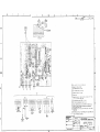
4.
THIS
3.
MICROPHONE ARE
2.
SO1 I S A
1.
ALL
N0T E S : UNLESS
SHEET
APPLIES
TO
500
OTI-IERWISE
ARE
U N I T S ONLY.
OHM D Y N M I C
PUSH-TO-TALK
RESISTORS
SPK
1/4
TYPE.
MICROPHONE S W I T C H .
WATT.
SPECIFIED
CARBON
(SHEET
FILM.
+/-5%.
3 ONLY)
A
A
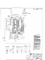
CONTRACT NO.
TW INTERCOM
SYSTEM
,
Drawn
R'NEILSON
.
Checked
RTS
C
DATE
8
I
7
I
6
I
5
I
4
I
3
Burbank.
California
.
----------Issued
SYSTEMS
S C H E M A T I C DIAGRAM. CC-300
FOR
SPK 300
RMS 3 0 0
W I R I N G FOR EXTERNAL MICROPHONES
FSCM
DWG NO
SIZE
I
6 057 2
8-18-89
2
REV
SD2712
ISHEET 3 o f
52712603
1
3 AG
cc2e
OPTlOlclAL
ELECTRET MIL
&
6 FOR
LOLAL POWER OPf IOU : RElYlOVE
5 CUDS.
Id MOVEL.5
.
8
Wir14
-L
D%,
ADD J6, AND WleE JL To P.L.6. AS SHOWN.
OV'TlOd, 53 I 5 h l ~ &ED.
r
C U T AhJb SLEEVE W l E E
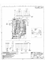
INSTALL JUMPERS IN PLACE OF 7 5 Oh1 RMS-3GO S E R I E S ONLY.
3
ItJ5TAI-L JUMPER, 15 (RTS*~Z=-CXXG-OO)
AND REMOM RIS ON 5%-309 SERIES OtJLY.
2 GOOSEUELIC MIC NOT USED ON
SERIES, cur 4 SLEEVE WIPE. EUDS.
I FOR MODELS WIT~OUT L I ~ H BoAeD,
T
CUT 4 SLEEVE WIRE ENDS.
NOTES: U h l L s S OTHEKW ISE CrPEClFIED
..."-w-c.
SPK-wo
-..",
DYN MIC
LIGHT BOARD
(~52620)
HEADSET
XLR-4-31
1
3
2
u*
4
53
MOMENTARY
"MIL w\l
\\
UI
1
-2 24 AWG
TO
I 0 PIN
CONN
52 ( ~ c H )
lORN l YEL 2 VIO 2 GRY l ERN I RED
RED
MOUNTING NUT
XLR-4
OPTIONAL
GOOSENECK
ELECTRET MIC
MIC
El IS A 3 m I T I O N TOGGLE SWITCH, C + K 7211 SPYABE
FOR WE 3CH OPTION* M3DIFY M E STANDARD CC-300 RC. BOARD
.AS FOLLOWS: CUT t TRACE
LZ
L3
4 I
MOMENTARY
LIGHT BOARD
HEADSET
MIC
urnonamma-
ou*.*M*IW
Ioulu*ea-:
-0cSy.YUI
5t
m*
.
.
.
a
00*lllFIm
.
I
ry.Iow.u
UIW
INSIALL JUMPERS IN PLACE OF T5 ON RMS -300 SERIES ONLY.
I~~~ITALL.JUMPEU
,T~(RTS*~~DL-OCC
IwQ
~-~
REMWE
~\
R15 ohl5PK-300 *RIES cI.lU.
GMS-K
.MK; UqT USED ON SPK-300 SERIES,CUT CSLENE W R E ENDS.
FOR MODELS WKHOUT 'LIGHT BOARD; CUT 4 .SLEEVE. WIRE M S .
RTS SYSiEh'iS
.---.WIRINE
9IAGFinM-SPVRMS
300
Lb-oj-&
J
3CCI
Q 3CH-L
OPT!ONS
SERIES 300
m..aml
R . ~ ~
-ukKm
11*1
-
o m
IEUT)
NOTES:
mWOTIC*LID1U.m(P
A
;O a 9 2
UU
WD 2712
8
I
7
6
1
4
5
I
3
ZONE
J4
J3
'INPUT*
AXR-3-31
D
. .
BLK
1
2
DATE
DESCRIPTION
REV.
I
"LOOP/EXT"
AXR-3-32
REVISIONS
I
SCE SHEET I
I
APPROVE0
I
D
~PERKER
CUT
\
Sl.E€V€
W\U€ E N D S
TO J Z (ZUI)
- ~ J ~ , P E -0
~ S : ~ c C t j ~ r ~( ~; PC- ~L T _ ~ :
Qb5,
@ REMOVF R57
FOR -DL OPTION.
@) R 3 \ CHhNGES FROM CbV. T O \ O K .
@$
-
R 2 4 CHANGES F R O M 220K 7 0 2211.
@
R E M O V E J'JMP LR C . '
3 ~-kr-i=.
U
@
V
Z
V
-
J
V
V
V
p
Z
Z
MOMENTRRY M \ C N O T JSED 3N 'JN \ T S W I T H CALL L \ G H l 1: T \ O N
\-L\. CUT
SLE"-\I'_ WIRE FHBS.
{
9
CUT TRRCES
V
ON C\RCU\T 5\DE-'.ZT-t.c55
CUT TRRCES O N COMPONENT S\DE. ( 3 Y L L C Z C ,
O
% $ > a $ $
!iib$$- 5
@ \NSTRLL JUMPERS \I PLACE OP
T3 O N RMS-?OO SER\ES ONLY
@ INSTALL JUMPER, T 5 ( R T s ~ z ? O ~ - O O O ~ - OM
O\I~D REMOVE R I 5
0;J 5 P K - 3 0 0 SERIES OIJLY.
@ GOOSENF-CU M\C
NOT IJCEC '3N cPU- 100 5c4\EC. CUT
\ SLEEVF
W\RE. ENDS.
OPT\ONRL
ELECTRET M\C
A
MOMENTARY
M \C
CARBON
M\C
0
TO
MOUNTING
NUT
XLR-4 -31
NOTES : :JNLESS O?HEUW\SE SPEC\F\ED.
io
LIGHT
BOARD
UNLESS OTHERWISE SPECIFIW
DlYENSKmS ARE ffl INCHES
TOLERANCES ARE:
F R A M S DECIYLLS MOLES
JJT0
GOOSENECK
M\c
.U+
COWIRLCT No.
SER\ES 300
APPROVAU
.UX=
MATERIAL
fikflPflgDRAW
CHECKEO
FIMSH
IWED
DO N O T SCALE DRAWING
A
RTS SYSTEMS
BURBANK, CALIFORNIA
f
DATE
ll- 1%%3
W \R\NG D\hGRAV4
SPK/RMS - 300-ni
4,
1
2
1
i
REYIIIK)NII
mr*
MV.
~
DAN
MICIIYMI(
H
~
E R EOV I S IR
--..._Y-7tW_-84IZ:..--~
~
RT5 CINE ( ~ C H )
RTS LINE ( ~ c H )
SPEAKER
3
CONN
CUT t SLEEVE
WIRE ENDS
I
ADD 5ARINK Fl T FOR
I
P7
ULRAD
#30 -455
WHT
.
I
Umovm
XLR-4-32
.
LOOP THRU/ EXT
YSTEMS INC.. HURBANK. C
\
3 POSITICNJ
L
< K 7203SPYABE
DUAL 5 D K A674MZIO
(RT51L 1407- 0022-00)
-
( RTS* 1903-0025-00)
b
JI
A
I
Q
7 MOMEtJTARY MIL MOT USED ON UUITS WITH CALL L ~ h n OPTlotd
l
O
(-I-').CUT 1 SLEEVE WIRE ENDS.
@ CUT
TRACES
Q CUT
T ~ A C E 0t.1 COMPO~.IE~JT
SIDE (OUB PLACE).
@ IdSTALL
@ IlJSTALL
ou
CIRCUIT SIDE (TWO PLACES>.
JUMPERS
1t.I
PLACE
OF 75 0k.l RMS-300 SERIES ONLY
JUMPER,T ~ ( R T ~ ' + z ~ C L - O W
AND
~-O
REMNk E l 5
O N SPK-300 SERlE'3 ONLY'.
@ GOOSEhlELK
M I L NOT USED
SLEEVE WIRC ENUS.
@F
0PllokJAL
ELECTRET M I L
GMSENECK
MIL
LIGHT BOARD
R
ON S P L - 3 0 0 5ERIES. CUT AUD
MODELS WITHOUT L14hT gOlsRD, CUT 4 SLEEVE N I P E EtJDS.
r\lOrES UhJLffi
OTHERWISE S P E C I F I E D
HEADSET
/'
J3
J5
XLFE!
REAR PANEL
-.
-...
BLK
I
-*
..
ULW
,
RTSU)I~;CH)
BRN
-
J4
\
I
-------
/h Fdi: PbZo&I?AMl INPUTOCOIN-)P:I
A
I
SEE SHEET OIJE
1 .
.
I
DUAL 5OK AUDIO
(RTS # 1407-0022-00)
R E M O V ~JUMPERS AT U 3 PIUS 5,6<7.
FOR PROGRAM INPUT Cc) oPf10t.I : ADD cz(. I /50),clo(lmp~), cl0 (.ml/lCO), C Z B ( Z P ~ F > ,
C107$ LIOB(Z.Z/~O),Kll4 PI3 (47<), ~23[150K), R4q(1oK), R51(ICOY), K 5 2 ( 2 ~ ~ ) , 1 4 ( L M 4 ~ 3 5 ,
us(3sset S-PIN s o c ~ , ~ ~ ) c t i ~Ff~ fOiM~SIM&LE
k ~ TO DUAL R?T, LH*€
R31 VALUE Ti IOK.
1t.l
MODELS hh1i-i - L OPTlOlrl, 53 15 NOT USED CUT AtJD SLEEVE
IM\TAL JUMPERS IN M E OF 7-'i (M RM5-,500 SERIES OM!!.
IN?TAU, JUMPEC $ T ~ ( R T S *23DLo-COL-CO\ PNO REMWE R\5 0t-I SPK-300 SERIES ONLY.
b0qENU.K M\LNOT USED. 0l.l S P K - ) ~ ~ L ~ I ' ~ \CWE
~ C T ~w\$
~ ENW
WR .MObELS W\MOVT L\hUT'BOARD, CUT^ SCENE-W \RE ENDS.
.
m:UNLESS .OTHERWISE
(
SPECIFIED.
A
RTS SYSTEMS BURBANK. CALIFORNIA
REtJoVE K57 FDE.PRO&~MIIJPuT (-c)oPTloM,
(-GI:O?TIO~ < A6D .J5 70 PEA=
IUPUT
I I. FOR PRo~EAIY~
PANEL, MIKE A 5 W N G .
ADD JUMPER FOR fX+tZAM
CUT
T~ACE
F ~ R&&PAM
f PROC&W.
W\RINh T)\A6RAM.- '?PI( IRMC,. ,500
IMPLIT (-C) OPTlOhJ,
IUPLIT (-c) OP~IO?.
PROGRAM INPUT OPTION (c)
(DO NOT.USE WITH DL)
.
I~PUT(-L)OPTIO~J: MOVEJUMPER
JMP I 4 3MP2 TO
l ;U
.I JMPZ.
?;7ie:r
YXlM
.
.
-1'
.
. . AF
OF II :
I
REVISIONS
DESCRIPm
lN
REV.
ZONE
i
I
SEE SHEl7 I
DATE
I
.CUT $ SLEEVE
W I R E ENDS
8.
For
Unmritched
label information
mic) seeon
drawing
RMSWBCS
FDXXMC(Dual Usten. Programinput, end
A
FRoUT PANEL
On RMS300 unlts a&:transformer T5 is not Installed. Add two 24 ewg red
i
jumpers in placeofT5 on bottom side of the board as shown.
/3\
On SPK300 UnftSm installjumper across S1. InstalltrensformerT5 (RTS
#23060006W), and remove resistor R15.
Gooseneck mic not Installedon SPKW units. Cut and sleevewire ends.
For options withoute light board (CC26) cut and sleeve wire ends.
To
NOTES:
MOUhlTidG NUT
X LR-4 -3 1
GooSENECK
MIL
V
LIGHT BOARD
MOMENTARY
M!L
PROVED
i
I
1
CUT
3
2
.CH2
10 JI
A
A
26 PI^ LDNY
FOR RHC OPTION (+M) ADD J 5 (XLR-4-31)BACK PANEL
ERASE PROGRAM INPUT, LABEL "REMOTE HEADSET"
WlRE TO THE FRONT PANEL A5 SHOWN.
5. FOR -USMB(S):
a)ADD : T 4 (LM9003),C107 { C108 (10/50 ELECT RADIAL),
QTY I JUMPER, CITY I BUS WIRE.
b) BACK PAAJEC:
ELIMINATE 'LOOP THRU* WIRES BETWEEN XLR-3-31 (RT5 LINE)
AND d 4 (LOOP THRU).ERASE "LOOP" FROM BACK PANEL.
ENGRAVE "USM'' INSTEAD. WIRE J4 A5 SHOWN.
MOUNTILJG NUT
L2 L 3
X LR-4
ELECTRET M I L
IPPAOVED
I
-7
oPTlohlAL
DATE
SEE SHEET I
X
I
CHI
DLJCR~PIION
Rr5 LINE (2CH)
RTS LINE (3CH)
SPSKER
AEVlSlONS
& SLEEVE
Goo5EtJECK
MIC
CAR BaJ
MI C
A
A
L4
LIGHT BOARD
2
/r\
INSTALL JUMPER IN PLACE OF T 5 ON R M 5 - 3 0 0 SERIES ONLY.
INJTALL JUMPER AND REMOVE R15 ON SPK-300 SERIES ONLY.
GOOSENECK MIC NOT USED ON S P K - 3 0 0 SERIES,
FOR MODELS WI7HOUT LIGHT BOARD, CUT
6 SLEEVE
WIRE ENDS.
C O r n A C T No
RTS SYSTEMS
UPROVALS
WIRIAJG DIAGRAM,
MODEL SPK/RMS -300- U5M 6 (s)
on~lyw
R. AlEIL5ON
10-4-88
CHECKED
IWED
NEXTAU*
APPLICATHIN
U.I*-MID
m-
DO NOT SCALE DRAWNa
I
BURBANK, CALIFORNIA
DATE
SITE ~ X Y
NO.
D 60572
A,
-(
DWO
w.
RN.
WD 2712
Iu*"
AF
8oF
\\
GmSENECK
OPTlOhlAL
ELECTRET M I C
MIL.
AMACE
UP
3 P T LOtJb CABLE AS SHOW^ ItJ
"762-'L" "782-3"CISIN6 B p i I-IELvETIcA
DETAIL A . MAK6 WIPE LAEELS "TBZ-1".
LIhHT, ELK orJ C L E M TAPE. PLUG CONEJECTOR
A
k,
INTO THE ' I S O " C q N N ~ T a RON
T H E 6hLZ
PANEL.
u i u ~OIHERWISE
UNLESS
n ARE
~ ~ INmIWHES
SPECI~LD
~
AusE Ahl XLR-5-32 FOR TIIE"ISO"CON~!EL~R.W I R E
A 5 SWWu.
5. DELETE ~ I L K S L R E E ~*LOOP/EXT*
J
FROM BACK PANEL. COVER 1.~11i-i
LABEL "150".
(MAKE'XSO' LABEL WITH U R N 7YPE. 8 p T HEWETILA L I ~ ~ H T
!
7 5 ON KMS-300 5 E K l E 5 ONLY.
3 1hI5l-ALL JUMFER , 15 ( R T S ~ Z W - 0 d 0 6 - 0 0 ) AND REMOVE R 1 5 ON '3%-3a0 ~ € R I E SOULY.
2 GoC~ENECKMlC NOT USED ON 5PK-%I0 SERIF-5, CUT 4 S L E E V E W I K E E N D S .
I FOR MODEL5 W l'lHOUT LIGHT WAtZD, C u r d SLEEVE WIRE ENDS.
INS'TAU JUMPEES IN R A C E OF
NOTES: U h l L E S 5
OTHERWISE S P E C I F I E D
A FOE
ul\r~TsMITH -3ct.I (A) OPTlotJ OULY:
~ ) 3 315 AN XLR-4-31 &NNELTOiZ
B ) S IS
~ AtJ 3-POSITIONS W I T L H ( R T S ~ I ~ O ~ - 0 0 3 - 0 0 )
L> R90 (loole) 4 C47 (Io,F/so\/)
A E E ADDED
T M E R A W I S ARE:
m A C m D€CIYU(I
"" *
CONTRACT No.
s~a1e5
300
MLES
-*
APPROVALS
.XXXr
A
YATEllAL
DRAW
R.T.CI?UZ
DATE
215.89
CHECKED
FIIUSH
ISSUED
-
DO NOT SCALE DRAWING
RTS SYSTEMS
WIRItJ6
A
BURBANK,
CALIFORNIA
DIAGRAM
*
-
R M S W - V I (&>, S P K 3 a - V f ( x ~ ) ,
R M5300-3~
H-VI (A*~),SP~<W-%H-V~(AXB)
SIZE FICY w.
D 60572
I
owo. no.
REV.
WD2712
AF
3
I
2
I
1
REVISIONS
ZONE
I
1
DlTE
OESCRlPrlON
REV
I
I
I
SEE 5HEET I
APPROVED
I
RT5 UNE (2 CH)
XLR-3-32
CUT
'
\
SLEEVE
W\RE € N O S
@ REMOVE
R57 FOR -DL OPTION.
Q R 3 \ CHhNGES FROM 5 b K T O \ O K .
@ R
A
CHRNGES FROM 220'6 TO 22K.
24
@
@
REMOVE
@)
MOMENTRRY M \ C N O T USED DN UNITS W\TH CALL L\GHT OPT\OM
L-L).
CUT
SLEEVE W\RE ENDS.
WEMOVE W7.
@ UJT
'
JUMPERS.
@CUT
TRhCES O N C\RCU\T 5 \ D E .
T R R C E S ON C O M P O N E N T S\DE.
an
\NSTPILL JUMPERS \N PWCE Of T 5 ON RM5-300 SER\ES O!\\LY.
L.2
INSTALL JUMPER, T5 (RTS* 2%-0006-00) MID REMOVE R I G
Ctd GPK-300 SERIES 0tJLY.
Goo:,wKK
w\c wT USED ON spu-300SER\ES. CUT t, %LEEvE
WIRL WUS.
QFOR PDDELS
ELECTRET M\C
M\C
;,
WITH OUT UGHT BORRD, cu-\ SLEEVE WIRE ENDS.
NOTES : UNLESS OTHERW\SE SVEL\F \FD.
~RT~SYSTEMS
MYENSIOHS ARE IN INCHES
T O C E ~ A H C ~ARE:
S
BURBANK CALIFORNIA
APPR0V)LS
I
CHECKED
W \R\NG D\RGRF,M,
SPK/RMS-~D-D.-M~~(BXV OPTIONS)
-.
-
-
--
J3
~5
m-I
REAR PANEL
RTLUM$'CHJ
"PROGRAM
IAI"
-
SEE-SHEET
orJc
LT (S\OPTIO~~ W ~ E UP R h W
PRE~EIJ'~:
a. ADD 13 (~1.19003), LI05 $ L 1 0 6 ( 1 0 ~ ~ / 5EL=).
0~
B u s Wire
ADD @Z4/W& RED JUMPER F%M E b T O U5M. "22
JUMPER FIZOM €5 70 €7. ,
J4 "LOOP" CoNNW;ToR 15USED FOR 'USM " CON~JECTOR.
ERASE. 'WW/F_XT"
~ILK~CEENI~A
G m LABEL "USM': kJipE hS 5H0Wd.
7. FOR uw=z~~lcdav
BALANCED MIL
tlJp~T0 W l 0 d
DUAL 5 0 K AUDIO
(RTS # 14.07-0022-00)
IS
&,
A
I
'
<
6
FOR P K ~ & $ ~ INFUT
M
(L) OPTIO~:
m:cr(. 1/50). o o ( ~ r n & , cue (.ml/m), i r e ( o r ~c1o7
, r CIOW'Z.Z/~O),
a11c K I 3
(47~),I?Z3(1501c).
R49 (low),
351 (1oor),~~5z(zzr),~4(~1"19003~,
L H A k b E R31 VALUE. 70 IOK.
REMoVE J U M F R S 4
r U 3 nlJS 5.6 4 7.
M e JuMPI~KFPOM JMPI 4 JMPZ TO US-l 4 JMPZ
CUT TnAcE od c l R c u ~ TSIDE.
ADD *24 AWP &KY JUMWK ~ ~ 0 rPZ
- l TO E B , * ~ ~ A &us
W ~ UIEE JUMPER
FRo.t.4 F-7TO 4 5 L .
ACU J5 To R E A R PfWeL. WIRE A 5 St-lOkJd.
L. 8
REMOVE
F57.
IU MODELS
4 IIJSTALL
fiOUNnNL1 IWXLR- 4
53
MOMENTARY
6005Et.I.la~~
MIL
MIC
M N l I40
\
" MIC ON"
Lid 05-115
A
A
WITH - L OPllod,S3 IS tJoTU5ED. U T
JUMPES
IdSTALL JUMFER
11.1
OF
< SLEEVE WlEE EFIDS,
T5 o d K M S - 3 c o SPIK
oIJLY.
T ~ ( R T ~ * ~ ~ & - ~ w ~ - =MOM
~ ) A N DE l 5 OM %-W
<ERIES OMLY.
6 a r ; t h l ~ cMIL
~ IJOT USED d SPIC-3005EmE5,LuTIY E E V E W I E EtJDS.
/I\ FOR MODELS l-.J~'lHOurL l 6 l d BOARD,CUT t SLEEVE WIRE EN=.