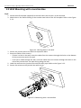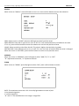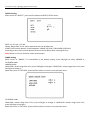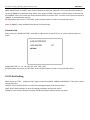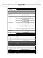
1
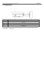
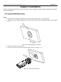
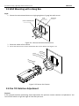
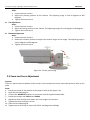
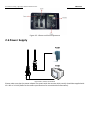
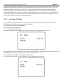
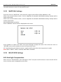
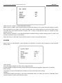
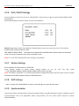
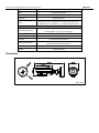
DS‐2CC1173P(N)‐VF(IR) Day / Night High‐definition Bullet Camera User Manual V 1.2.0 User Manual of Day / Night High‐definition Bullet Camera 1 Thank you for purchasing our product. If there are any questions, or requests, please do not hesitate to contact the dealer. This manual applies to DS‐2CC1173P(N)‐VF(IR) Bullet Camera. This manual may contain several technical incorrect places or printing errors, and the content is subject to change without notice. The updates will be added to the new version of this manual. We will readily improve or update the products or procedures described in the manual. DISCLAIMER STATEMENT “Underwriters Laboratories Inc. (“UL”) has not tested the performance or reliability of the security or signaling aspects of this product. UL has only tested for fire, shock or casualty hazards as outlined in UL’s Standard(s) for Safety, UL60950‐1. UL Certification does not cover the performance or reliability of the security or signaling aspects of this product. UL MAKES NO REPRESENTATIONS, WARRANTIES OR CERTIFICATIONS WHATSOEVER REGARDING THE PERFORMANCE OR RELIABILITY OF ANY SECURITY OR SIGNALING RELATED FUNCTIONS OF THIS PRODUCT.” User Manual of Day / Night High‐definition Bullet Camera 2 Safety Warnings and Cautions Please pay attention to the following warnings and cautions: Hazardous Voltage may be present: Special measures and precautions must be taken when using this device. Some potentials (voltages) on the device may present a hazard to the user. This device should only be used by employees from our company with knowledge and training in working with these types of devices that contain live circuits. Power Supply Hazardous Voltage: AC mains voltages are present within the power supply assembly. This device must be connected to a UL approved, completely enclosed power supply, of the proper rated voltage and current. No user serviceable parts inside the power supply. System Grounding (Earthing): To avoid shock, ensure that all AC wiring is not exposed and that the earth grounding is maintained. Ensure that any equipment to which this device will be attached is also connected to properly wired grounded receptacles and are approved medical devices. Power Connect and Disconnect: The AC power supply cord is the main disconnect device to mains (AC power).The socket outlet shall be installed near the equipment and shall be readily accessible. Installation and Maintenance: Do not connect/disconnect any cables to or perform installation/maintenance on this device during an electrical storm. User Manual of Day / Night High‐definition Bullet Camera 3 Power Cord Requirements: The connector that plugs into the wall outlet must be a grounding‐type male plug designed for use in your region. It must have certification marks showing certification by an agency in your region. The connector that plugs into the AC receptacle on the power supply must be an IEC 320, sheet C13, female connector. See the following website for more information http://kropla.com/electric2.htm. Lithium Battery: This device contains a Lithium Battery. There is a risk of explosion if the battery is replaced by an incorrect type. Dispose of used batteries according to the vendor’s instructions and in accordance with local environmental regulations. Perchlorate Material: Special handling may apply. See www.dtsc.ca.gov/hazardouswaste/perchlorate. This notice is required by California Code of Regulations, Title 22, Division 4.5, Chapter 33: Best Management Practices for Perchlorate Materials. This device includes a battery which contains perchlorate material. Taiwan battery recycling: Please recycle batteries. Thermal and Mechanical Injury: Some components such as heat sinks, power regulators, and processors may be hot; care should be taken to avoid contact with these components. Electro Magnetic Interference: This equipment has not been tested for compliance with emissions limits of FCC and similar international regulations. This device is not, and may not be, offered for sale or lease, or sold, or leased until authorization from the United States FCC or its equivalent in other countries has been obtained. Use of this equipment in a residential location is prohibited. This equipment generates, uses and can radiate radio frequency energy which may result in harmful interference to radio communications. If this equipment does cause harmful interference to radio or television reception, which can be determined by turning the equipment on and off, the user is required to take measures to eliminate the interference or discontinue the use of this equipment. Lead Content: Please recycle this device in a responsible manner. Refer to local environmental regulations for proper recycling; do not dispose of device in unsorted municipal waste. User Manual of Day / Night High‐definition Bullet Camera 4 Safety Instruction These instructions are intended to ensure that the user can use the product correctly to avoid danger or property loss. The precaution measure is divided into ‘Warnings’ and ‘Cautions’: Warnings: Serious injury or death may be caused if any of these warnings are neglected. Cautions: Injury or equipment damage may be caused if any of these cautions are neglected. Warnings Follow these safeguards to Cautions Follow these precautions to prevent serious injury or death. prevent potential injury or material damage. Warnings: 1. Please adopt the power adapter which can meet the safety extra low voltage (SELV) request. And source with DC 12V or AC 24V according to the IEC60950‐1 and Limited Power Source standard. 2. If the product does not work properly, please contact your dealer or the nearest service center. Never attempt to disassemble the camera yourself. (We shall not assume any responsibility for problems caused by unauthorized repair or maintenance.) 3. To reduce the risk of fire or electrical shock, do not expose this product to rain or moisture. 4. This installation should be made by a qualified service person and should conform to all local codes. 5. Please install blackouts equipment into the power supply circuit for convenient supply interruption. 6. Please make sure that the ceiling can support more than 50(N) Newton gravities if the camera is fixed to the ceiling. User Manual of Day / Night High‐definition Bullet Camera Cautions: 5 1. Make sure the power supply voltage is correct before using the camera. 2. Do not drop the camera or subject it to physical shock. 3. Do not touch sensor modules with fingers. If cleaning is necessary, use a clean cloth with a bit of ethanol and wipe it gently. If the camera will not be used for an extended period of time, put on the lens cap to protect the sensor from dirt. 4. Do not aim the camera at the sun or extra bright places. A blooming or smear may occur otherwise (which is not a malfunction however), and affecting the endurance of sensor at the same time. 5. The sensor may be burned out by a laser beam, so when any laser equipment is being used, make sure that the surface of the sensor will not be exposed to the laser beam. 6. Do not place the camera in extremely hot or cold temperatures (the operating temperature should be between ‐10°C ~ 60°C, dusty or damp locations, and do not expose it to high electromagnetic radiation. 7. To avoid heat accumulation, good ventilation is required for a proper operating environment. 8. Do not let water and any liquid flow into the camera. 9. While shipping, the camera should be packed in its original packing, or packing of the same texture. 10. Improper use or replacement of the battery may result in hazard of explosion. Replace with the same or equivalent type only. Dispose of used batteries according to the instructions provided by the battery manufacturer. User Manual of Day / Night High‐definition Bullet Camera 6 Table of Contents Chapter 1 Introduction...........................................................................................................................7 1.1 Product Features...........................................................................................................................7 1.2 Chief Introduction about Function ...............................................................................................7 1.3 Appearance...................................................................................................................................9 Chapter 2 Installation...........................................................................................................................10 2.1 Simple Wall Mounting ................................................................................................................10 2.2 Wall Mounting with a Junction Box............................................................................................11 2.3 Wall Mounting with a Gang Box .................................................................................................12 2.4 Pan Tilt Rotation Adjustment .....................................................................................................12 2.5 Zoom and Focus Adjustment......................................................................................................13 2.6 Power Supply ..............................................................................................................................14 Chapter 3 Menu Description................................................................................................................15 3.1 Menu Interface ...........................................................................................................................15 3.2 Menu Details ..............................................................................................................................15 3.2.1 Camera ID Settings ...............................................................................................................15 3.2.2 Lens Type Settings ................................................................................................................16 3.2.3 WHITE BAL Settings ..............................................................................................................17 3.2.4 BLC/ECLIPSE Settings ............................................................................................................17 3.2.6 DAY / NIGHT Settings............................................................................................................19 3.2.7 Shutter Settings ....................................................................................................................19 3.2.8 AGC Settings .........................................................................................................................19 3.2.9 Synchronization ....................................................................................................................19 3.2.10 Language................................................................................................................................20 3.2.11 Special Function.....................................................................................................................20 3.2.12 Exit Setting.............................................................................................................................25 Appendix ..............................................................................................................................................26 User Manual of Day / Night High‐definition Bullet Camera 7 Chapter 1 Introduction 1.1 Product Features This series of cameras utilizes a high performance sensor and advanced print circuit board design technology with high resolution, low distortion and low noise, etc. Key features are: High performance SONY CCD, for high definition and image clarity. Low illumination (Please refer to the specifications for details). ICR filter auto switch . High light suppression for a clearer image in strong light. OSD menu, enables user to configure the operating parameters. Advanced stepping motor and sleep mode to avoid ICR oscillation. BLC with programmable BLC area. ATW ‐ Auto White Balance with high color rendition. High SNR for clear and pleasing image. Auto Electronic Shutter control to adapt to different environments. AGC ‐ Auto Gain Control, adaptive brightness. Auto Iris. Privacy mask with 8 optional colors and 8 configurable areas. Advanced design technology with high reliability. Advanced 3‐axis design to meet different mounting requirements. Advanced double‐plate design to guarantee CCD heat dissipation and image quality. 3D digital noise reduction. IR SMART prevent close quarters picture from overexposure. 1.2 Chief Introduction about Function Motion Detection: In the user‐defined motion detection surveillance area, the moving object will trigger alarm. User can select suitable sensitivity level according to corresponding environment. Privacy Mask: In the surveillance area, user can cover some place to protect others’ privacy. The number of privacy mask area is up to 8. 8 User Manual of Day / Night High‐definition Bullet Camera DAY&NIGHT Auto Switch: The camera will display color image and become monochrome automatically at night. AGC: When object being shot looks dim, please turn on AGC. It is propitious to enhance brightness. To output standard video under different illumination, the range of auto gain control must be large enough. When under low illumination, AGC will increase camera’s sensitivity, and output bright and clear video. S/N ratio: It is the ratio of Signal voltage and noise voltage. The ratio is larger, the effect of noise is less, and the image is more spotless. OSD (On Screen Display): The camera supports friendly menu interface on the screen, and it’s convenient for user selecting expected function. 3‐axis adjustment: Adopt advanced 3‐axis mechanism design meet different mounting requirement by flexibly adjusting the lens into the required angle. Synchronous System: Synchronization usually contains power synchronization and internal synchronization. Internal synchronization uses synchronous signal which is generated by camera’s crystal oscillator to complete synchronous scan. Power synchronization uses synchronous signal which is generated by camera’s adaptor to complete synchronous scan. White Balance: Because the camera could not adjust the color temperature according to the light alteration as the eyes, that will cause color deviation. White balance is the white rendition ability of the camera to adjust the problem according to the environment automatically. ICR Auto Switch: The filter will filter infrared light during the daytime and change to normal filter at night to ensure a high sensitivity and clear image. BLC: If there is glaring light in the background of the object being shot, the object will look very dim. In this situation, turning on BLC function will make the object look bright and clear, but the background scene will be overexposure. BLC OFF BLC ON User Manual of Day / Night High‐definition Bullet Camera 9 1.3 Appearance Serial NO. Description 1 Sun shade 2 Front cover 3 Main body 4 Bracket 5 Wire hidden box 3‐axis: Easy to adjust desired focus and scene by turning and moving the 3‐axis camera bracket by hand. X‐axis: 0~360° Y‐axis: 0~90° User Manual of Day / Night High‐definition Bullet Camera 10 Chapter 2 Installation Before mounting, please make sure that the device in the package is in good condition and all the assembly parts are complete. 2.1 Simple Wall Mounting Steps: 1. Attach the drill template (supplied) to the wall where the camera is to be mounted. 2. Make holes in the wall according to the number one holes of the drill template. Refer to the Figure 2.1.1. Wall Drill Te m plate Figure 2.1.1 Drilling Holes in the Wall 3. Route the cables of the camera. 4. Secure the camera to the wall with expansion bolts. Refer to the Figure 2.1.2. Drill T emp late Mou nting Base Figure 2.1.2 Secure the Camera 11 User Manual of Day / Night High‐definition Bullet Camera 2.2 Wall Mounting with a Junction Box Steps: 1. Attach the drill template (supplied) to the wall where the camera is to be mounted. 2. Make holes in the wall according to the number two holes of the drill template. Refer to the Figure 2.2.1. Wall Drill Te m 3. 4. 5. 6. plate Figure 2.2.1 Drilling Holes in the Wall Secure the junction box to the wall with expansion bolts. Route the cables of the camera. · If there is a hole in the wall, route the cables from the camera through the holes on the bottom of the junction box and in the wall. · If no hole is made through the wall, route the cables from the camera through the holes on the side of the junction box. Use open wiring along the wall. Hook the camera to the junction box with the safety rope. Refer to the Figure 2.2.2. Secure the camera to the junction box with screws. Junc ti Safe ty Ro on Box pe A ngle Safe ty Ro p e Brac ket B ase Drill Tem plate Figure 2.2.2 Mounting with a Junction Box 12 User Manual of Day / Night High‐definition Bullet Camera 2.3 Wall Mounting with a Gang Box Steps: 1. Secure the camera attachment to a single‐gang box or 2‐gang box with screws. Wall Gang Box Camera Attachment Figure 2.3.1 Secure the Camera Attachment 2. Route the cables of the camera. 3. Secure the camera to the camera attachment with screws. Refer to the Figure 2.3.2. C am era A t Gang Box tach men t Brac ket B ase Figure 2.3.2 Secure the Camera 2.4 Pan Tilt Rotation Adjustment Purpose: 3‐axis (pan/tilt/rotation) positioning allows adjustment for optimum camera rotation and placement. You can use this function to get the angle of view that you want. 13 User Manual of Day / Night High‐definition Bullet Camera Pan Adjustment Steps: 1. Loosen the lock screw‐1. 2. Adjust the panning position of the camera. The adjusting range is from 0 degrees to 360 degrees. 3. Tighten the lock screw‐1. Tilt Adjustment Steps: 1. Loosen the lock screw‐2. 2. Adjust the tilting position of the camera. The adjusting range is from 0 degrees to 90 degrees. 3. Tighten the lock screw‐2. Rotation Adjustment Steps: 1. Loosen the lock screw‐3. 2. Rotate the rotation position to adjust the azimuth angle of the image. The adjusting range is from 0 degrees to 360 degrees. 3. Tighten the lock screw‐3. Figure 2.4.1 3‐axis positioning 2.5 Zoom and Focus Adjustment Purpose: There is a place under the bottom of the camera. You can adjust the zoom value and the focus value in this place. Steps: 4. Loosen the screw at the bottom of the camera. Refer to the figure 2.5.1. 5. Open the lens adjusting lid. 6. Connect the MONITOR interface to a monitor with the supplied video cable. 7. Loosen the screws near FOCUS and ZOOM. 8. Adjust the zoom and focus to obtain the clear image in the monitor. 9. Tighten the zoom and focus screws. 10. Close the lens adjusting lid. 11. Tighten the screw firmly to secure the lid for avoiding water leakage. User Manual of Day / Night High‐definition Bullet Camera 14 Figure 2.5.1 Zoom and Focus Adjustment 2.6 Power Supply Figure 2.6.1 Camera connection Please make sure that the power adapter can match with the camera which usually should be supplied with 12 V DC or 24 V AC (Refer to the camera specifications for more detailed information). User Manual of Day / Night High‐definition Bullet Camera 15 Chapter 3 Menu Description 3.1 Menu Interface Press menu button, the OSD menu will show on the screen. Press up/down button to move up/down cursor, left/right button to select the different options; 3.2 Menu Details 3.2.1 Camera ID Settings Press up/down to move cursor to “CAM ID”, press left/right to enable or disable this setting. ON/OFF: Display the camera ID on the screen or not. Select “On” , and press confirm button to enter the “CAM ID “menu. Press up/down to move the cursor to choose characters, numbers, symbols, and press confirm button to User Manual of Day / Night High‐definition Bullet Camera 16 modify the camera ID; press left/right to move cursor to the character of camera ID, press confirm button to change the characters of camera ID on the discontinues line; move the cursor to the “CLR” to clear all characters inputted, move the cursor to “POS” setting, and press confirm button to enter the CAM ID position setting menu, then press up/down to change the position of camera ID, press confirm button to exit the CAM ID position setting menu, and return to the CAM ID menu; move the cursor to “RETURN” and press confirm button to return to the previous menu. Move the cursor to “EXIT”, press left/right to “SAVE”, press confirm button to exit and save CAM ID setting. 3.2.2 Lens Type Settings Press up/down to move the cursor to “LENS”, and press left/right to select the lens type as ELC or ALC. ELC uses auto electronic shutter to adjust the brightness; ALC uses auto iris to adjust the brightness; Note: ELC: auto shutter, fixed iris; ALC: auto iris, fixed shutter. Select ELC and press confirm button then the “ELC Setup” menu is showed on the screen. Press up/down to move the cursor to the “VALUE”, press left/right to adjust brightness, move the cursor to “RETURN” and press confirm button to return to the previous menu. Note: Different values represent the different brightness. Select ALC and press confirm then “ALC Setup” menu is displayed on the screen: User Manual of Day / Night High‐definition Bullet Camera 17 Move the cursor to “VALUE”, press left/right to adjust the menu. Move the cursor to “RETURN” and press the confirm button to return to the previous menu. 3.2.3 WHITE BAL Settings Press the cursor to “WHITE BAL”, then press left / right to select ATW1, ATW2, MANUAL or ATC. ATW1: Auto traced balance mode 1, built‐in algorithm for automatic white balance setting. Usually used for indoor environment. ATW2: Auto traced balance mode 2, built‐in algorithm for automatic white balance setting. Usually used for outdoor environment. Manual WB setting is as below: Select “MANUAL” and the menu is displayed on the screen: Press up/down to “BLUE” and “RED”, then press left/right to adjust the value. Then move the cursor to “RETURN”, press confirm button to return to the previous menu. ATC: Automatically white balance control , usually used for place that color temperature is stable. Note: When “NIGHT” mode is selected, WHITE BAL is disabled. 3.2.4 BLC/ECLIPSE Settings BLC: Back Light Compensation Move cursor to “BLC/ECLIPSE”, press left/right to “BLC” and press confirm button to enter the BLC SETUP menu. And the menu is displayed on the screen: User Manual of Day / Night High‐definition Bullet Camera 18 Move cursor to “VALUE” to select LOW, MID or HIGH. Move cursor to “AREA”, press confirm button to enter the submenu. First, press direction button to set the BLC area position as up, down, left, right or middle, then press confirm button to set the size of BLC area in the same way. Press confirm button to choose “RET” to return to the previous menu or “AGAIN” to reset position and size. Move cursor to “DEFAULT” to set VALUE and AREA to default setting. In default setting, VALUE is “MID” and position of the BLC area is in the middle. Move the cursor to “RETURN”, press confirm button to return to the previous menu. ECLIPSE Move cursor to “BLC/ECLIPSE”, press left/right to “ECLIPSE” and press confirm button to enter ECLIPSE SETUP menu. Value setting: Press left/ right to adjust the value, value ranges from 0‐8. ECLIPSE MODE: ALL DAY and NIGHT modes could be selected when highlight suppression is available. AREA setting: The position and size of ECLIPSE area could be set in the same way as BLC setting. DEFAULT: The default ECLIPSE area setting is full screen and default value is 4. Move the cursor to “RETURN”, press confirm button to return to the previous menu. User Manual of Day / Night High‐definition Bullet Camera 19 Note: move cursor to “BLC/ ECLIPSE” and press left/right to “OFF” to disable ECLIPSE and BLC function. 3.2.6 DAY / NIGHT Settings Press up /down to move the cursor to “DAY/ NIGHT”, and press left / right to select COLOR, NIGHT, AUTO. Auto Setting: Select Auto and press confirm button to enter the submenu: DELAY: Range from 0 to 63. The value 36 in DELAY option means the conversion time is 36 seconds between DAY mode and NIGHT mode. DAY→NIGHT/ NIGHT→DAY: The values here indicate that satisfied values, which means the threshold value of conversion between DAY mode and NIGHT mode. Note: If it is DS‐2CC1173P(N)‐VFIR, auto setting is unavailable. 3.2.7 Shutter Settings Press up/down to move cursor to “SHUTTER”. Press confirm button to select shutter speed: AUTO, ×2, ×4, ×8, ×16, ×32, ×64, ×128, × 256, 1/100000, 1/10000, 1/5000, 1/2000, 1/1000, 1/500, 1/250, FLK, 1/50. Note: FLK means “Flickerless”. It is used to eliminate the image flicker when the PAL system camera in 60Hz illuminant or the NTSC system camera in 50Hz illuminant. 3.2.8 AGC Settings “AGC” includes OFF, LOW, MIDDLE or HIGH. Press left/right to select desired mode. 3.2.9 Synchronization Internal and power synchronization are both available. When using DC12V power supply, it displays internal synchronization and is not adjustable. When using AC24V, user can select either internal or power synchronization. User Manual of Day / Night High‐definition Bullet Camera 3.2.10 Language The default Language is English. 3.2.11 Special Function Move cursor to “SPECIAL”, press confirm button and the menu is displayed on the screen. VIDEO Setting GAMMA Move cursor to “GAMMA”, and press left / right to set GAMMA value. GAMMA values include: USER, range from 0.05 to 1.00 with 0.05 interval. FREEZE Freeze current picture if it is ON. 20 User Manual of Day / Night High‐definition Bullet Camera 21 Motion Move cursor to “Motion”, press left/right to turn it on, press confirm button to enter the submenu: AREA: Move cursor to “AREA” and press left/right to select from four areas. AREA DISPLAY: Press left or right to turn it on or off. If it is off, motion detection is disabled in this area. If it is on, press confirm button to enter the submenu to set size and position of area. VALUE: Select sensitivity value from 0 to 40. The value is higher, the sensitivity is greater. MOTION DISP: Press left/right to turn it on or off. If it is on, the color of motion detection area is changed. Move the cursor to “RETURN”, press confirm button to return to the previous menu. MIRROR Move the cursor to “MIRROR”, press left/right to select “MID”,”H”,”V” or “OFF”. “H” represents horizontal, “V” represents vertical. ZOOM Move cursor to “ZOOM”, press left/right to select “ON”, press confirm button to enter: RATE: The maximum zoom rate is 32. Press left/right button to zoom in/out. H: horizontal migration V: vertical migration “H” and “V” are available when the image is magnified. User Manual of Day / Night High‐definition Bullet Camera 22 3DNR User can turn on or off the digital noise reduction. Press left/right to select “ON” and press confirm button to enter DNR SETUP menu: VALUE: Different values represent different noise reduction levels .The higher value, the better. Move the cursor to “RETURN”, press confirm button to return to the previous menu. POS/ NEG Move cursor to “POS / NEG”, and press left / right to select POS or NEG. If POS is selected, the video will be normal, If NEG is selected, the video will be negative. SHARPNESS Sharpness is adjustable from 0 to 31. Y GAIN Brightness is adjustable from 0 to 255. C GAIN Press confirm button to enter C GAIN menu: BLUE: Set blue value, range from 0 to 100. RED: Set red value, range from 0 to 100. User Manual of Day / Night High‐definition Bullet Camera 23 Move the cursor to “RETURN”, press confirm button to return to the previous menu. DEFECT Setting Move cursor to “DEFECT”, press confirm button to DEFECT SETUP menu: RATE: ×4, ×8, ×16, ×32, ×64. VALUE: Range from 1 to 6. Value represents the size of defect dot. START: Press confirm button, A notice appears: COVER THE LENS, THEN PRESS ENTER KEY. According to this, press confirm button to start to check defect after covering the lens. Note: Better to use this function in dark environment. DWDR Setting Move cursor to “DWDR”, it is unavailable in the default setting. Press left/right to select INDOOR or OUTDOOR mode. INDOOR mode: LOW‐LEVEL: values range from 0‐15, press left/right to change it. HIGH‐LEVEL: values range from 0‐15, press left/right to change it. Move the cursor to “RETURN”, press confirm button to return to the previous menu. OUTDOOR mode: LOW‐LEVEL: Values range from 0‐15, press left/right to change it. HIGH‐LEVEL: Values range from 0‐15, press left/right to change it. Move the cursor to “RETURN”, press confirm button to return to the previous menu. User Manual of Day / Night High‐definition Bullet Camera 24 PRIVACY setting Move cursor to “PRIVACY” , press confirm button and the menu is displayed on the screen: AREA: Move cursor to “AREA” , there are 8 default areas in different color and default position. AREA DISPLAY: You can select which area to display by selecting “ON”. Press confirm button to enter. And you can set size and position of the area. COLOR: The color of area could be changed by select the number range from 0 to 15. RETURN: Move the cursor to “RETURN”, press confirm button to return to the previous menu. IR SMART Move cursor to “IR SMART”, press left or right to turn it on/off. If it is on, press confirm button to enter: User Manual of Day / Night High‐definition Bullet Camera 25 VALUE: Range from 1 to 15 AREA: Move cursor to “AREA”, press confirm button to enter the submenu. First, press direction button to set the IR SMART area position as up, down, left, right or middle, then press confirm button to set the size of IR SMART area in the same way. Press confirm button to choose “RET” to return to the previous menu or “AGAIN” to reset position and size. RETURN: Move the cursor to “RETURN”, press confirm button to return to the previous menu. Note: IR SMART is only available when there is infrared lamp. SLOW SHUTTER Move cursor to “SLOW SHUTTER”, press left or right to turn it on/off. If it is on, press confirm button to enter: SLOW SHUTTER: × 2, × 4, ×8, ×16, ×32, ×64, ×128, ×256 . RETURN: Move the cursor to “RETURN”, press confirm button to return to the previous menu. 3.2.12 Exit Setting Move cursor to “EXIT” , and press left / right to select from SAVE, CANCEL and DEFAULT. Then press “enter” to exit the menu. CANCEL: Press confirm button to cancel the setting parameter and exit the menu. SAVE: Press confirm button to save the setting parameter and exit the menu. DEFAULT: Press confirm button to restore the factory default value and exit the menu. User Manual of Day / Night High‐definition Bullet Camera Appendix Specification Model Parameter DS‐2CC1173P(N)‐VF(IR) 560 TVL CCD ICR Vari‐focal Weather‐proof Bullet Camera Camera Image Sensor 1/3” SONY Super HAD CCD II Signal System PAL/NTSC Effective Pixels PAL: 752 (H) × 582 (V) NTSC: 768 (H) × 494 (V) Min. Illumination Shutter Time Lens Color: 0.1 Lux @ (F1.2, AGC ON), 0.0003 Lux @ (F1.2, AGC ON, sensitivity × 256) Color: 0.14 Lux @ (F1.4, AGC ON), 0.0004 Lux @ (F1.4, AGC ON, sensitivity × 256) B/W: 0.01 Lux @ (F1.2, AGC ON), 0.00003 Lux @ (F1.2, AGC ON, sensitivity × 256) B/W: 0.014 Lux @ (F1.4, AGC ON), 0.00004 Lux @ (F1.4, AGC ON, sensitivity × 256) ‐IR: 0.1 Lux @ (F1.2, AGC ON), 0.0003 Lux @ (F1.2, AGC ON, sensitivity × 256), 0 Lux with IR 0.14 Lux @ (F1.4, AGC ON), 0.0004 Lux @ (F1.4, AGC ON, sensitivity × 256), 0 Lux with IR PAL: 1/50 s to 1/100,000 s NTSC: 1/60 s to 1/100,000 s 2.8 ‐ 12 mm @ F1.4 Angle of view: 92° ‐ 27.2° Lens Mount φ14 Auto Iris DC drive Angle Adjustment Day & Night Horizontal Resolution Synchronization Video Output S/N Ratio Pan: 0 ‐ 360°, Tilt: 0 ‐ 90°, Rotation: 0 ‐ 360° IR cut filter with auto switch 560 TVL (Color), 600 TVL (B/W) Internal synchronization 1Vp‐p composite output (75 Ω/BNC) More than 52 dB Menu Camera ID On/Off (15 letters, adjusted position) Auto Gain Low/Middle/High/Off D/N Mode Auto/Day/Night Auto White Balance Privacy Mask Motion Detection BLC Excessive High Light Auto trace WB1/Auto trace WB2/Manual/Auto Control On/Off, maximum 8 zones On/Off Area/Value/Off Value 26 27 User Manual of Day / Night High‐definition Bullet Camera Compensation WDR Indoor/Outdoor/Off Anti‐flicker On/Off Language English/Chinese Video Gamma Correction, Digital Zoom, Digital Noise Reduction, POS/NEG ,Mirror, Sharpness, Y, C, Defect Pixel Correction General Operating Conditions Power Supply Weather Proof Rating IR Range Power Consumption Dimension Weight ‐10 °C ‐ 60 °C (14 °F ‐ 140 °F) Humidity 90% or less (non‐condensing) 24 V AC ± 10%, 12 V DC ± 10% IP66 ‐IR: approx 20 to 30 meters Max. 3.5 W ‐IR: Max. 10 W with IR cut filter on 96.9 x 84.2 x 315.4 mm (3.81” × 3.31” × 12.42”) 2100 g (4.62 lbs) Dimension Unit: mm