1
90-NET
UNINTERRUPTIBLE POWER SYSTEM
Restricted Sales Destribution
Warning: This is a product for Restricted Sales Distribution to informed partners. The
UPS may give rise to radio-frequency interference affecting other equipment in the vicinity; it is advised that the UPS not be positioned next to devices which, by their nature,
are sensitive to such interference (receivers/transmitters, radar, metal detectors, antitheft systems) and that cabling of such devices be kept separate from that of the UPS
wherever possible. It is also advised that the UPS input, output and external battery cables be
housed in earthed, metal conduits, or that shielded cables be used.
USER MANUAL
10H52168UM01 - Rev. 5
CHLORIDE 90-NET
ENG
All rights, including rights of translation, reproduction
by printing, copying or similar methods, even of parts,
are reserved.
Offenders will be liable for damages.
All rights, including rights created by patent grant or
registration of utility model or design, are reserved.
Delivery subject to availability. Right of technical modification reserved.
90-NET may differ from the one displayed on the front
cover.
Copyright © Chloride, 2008
Page 2
User Handbook - 10H52168UM01
- rev. 5 - 05/2008
CHLORIDE 90-NET
1. About these operation instructions .................................................... 9
2. Safety ................................................................................................... 11
3. Equipment delivery and storage ....................................................... 13
3.1. Transportation .............................................................................................. 13
3.2. Storage......................................................................................................... 13
4. Installation preparations .................................................................... 17
4.1. Unpacking .................................................................................................... 17
4.2. Transporting without packaging materials ................................................... 17
4.3. Selecting an installation site......................................................................... 17
4.4. Placement .................................................................................................... 18
5. Installation ........................................................................................... 19
5.1. Installation data ............................................................................................ 19
6. Power and signal connections........................................................... 33
6.1. Power connections ...................................................................................... 33
6.2. Cable lengths ............................................................................................... 35
6.3. Backfeed Protection..................................................................................... 35
6.4. 60-80kVA UPS power connections .............................................................. 36
6.5. 100-120kVA UPS power connections .......................................................... 37
6.6. 160-200kVA power connections .................................................................. 39
6.7. 250/300kVA UPS power connections .......................................................... 40
6.8. 400kVA UPS power connections ................................................................. 41
6.9. 500kVA UPS power and signal connections ................................................ 42
6.10. 600/800kVA power and signal connections ............................................... 43
6.11. Signal connections ..................................................................................... 47
6.12. Individual UPS signal connection information ............................................ 48
7. Battery connections ............................................................................ 49
7.1. Battery cabinet connections......................................................................... 50
7.2. Battery calculation settings .......................................................................... 53
8. Parallel.................................................................................................. 55
8.1. Installation - COC ......................................................................................... 55
8.2. Power and signal connections - COC........................................................... 59
8.3. COC power connection data ........................................................................ 60
8.4. 400/800A COC Power connections ............................................................. 61
8.5. 1600A COC Power connections .................................................................. 62
8.6. 3200A COC Power connections .................................................................. 63
8.7. Parallel signal connections ........................................................................... 64
9. System description ............................................................................. 71
9.1. Function ....................................................................................................... 71
9.2. Special features ........................................................................................... 73
User Handbook - 10H52168UM01
- rev. 5 - 05/2008
Page 3
CHLORIDE 90-NET
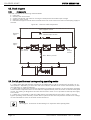
9.3. Block diagram ..............................................................................................
9.4. Switch positions and corresponding operating modes................................
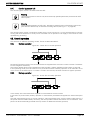
9.5. Operating modes .........................................................................................
9.6. Protection devices .......................................................................................
74
74
75
81
10. Operation........................................................................................... 83
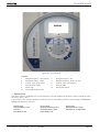
10.1. Control Panel and display...........................................................................
10.2. Inverter STOP/START procedures .............................................................
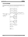
10.3. Controls and messages .............................................................................
10.4. Warning and Fault indications....................................................................
10.5. Troubleshooting .........................................................................................
83
84
86
91
94
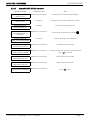
11. COC control panel............................................................................. 95
11.1. Control panel.............................................................................................. 96
11.2. 90-net diagnostics for parallel system with COC....................................... 96
11.3. COC messages normal condition .............................................................. 97
11.4. Desription of COC system stages ........................................................... 102
11.5. COC RESERVE stage description ............................................................ 104
11.6. COC UPS stage description..................................................................... 105
11.7. LOAD stage description........................................................................... 106
12. Operating procedures .................................................................... 107
12.1. Sample guided procedure - Manual Bypass ............................................
12.2. Centralised parallel system......................................................................
12.3. Parallel operation .....................................................................................
12.4. Guided procedure ....................................................................................
108
112
119
120
13. I/O functions .................................................................................... 125
13.1. List of Individual functions for single and modular parallel UPS ..............
13.2. List of individual COC functions...............................................................
13.3. I/O Function setting via PC terminal ........................................................
13.4. Description of function wiring with fixed terminal assignments..............
13.5. Electrical specifications of input/output signals .......................................
13.6. Table of functions ....................................................................................
13.7. I/O functions using interfaces X7 and X8.................................................
125
127
128
132
134
135
138
14. Interfaces ......................................................................................... 141
14.1. Standard interface COM - X6...................................................................
14.2. Computer Relay Interface - X7.................................................................
14.3. PPVis configured service interface - X3 ...................................................
14.4. X8 - Load Isolating Device (option)...........................................................
142
142
142
142
15. Standard equipment ...................................................................... 143
15.1. Device parameter special setting ............................................................ 143
15.2. Battery parameter setting........................................................................ 143
Page 4
User Handbook - 10H52168UM01
- rev. 5 - 05/2008
CHLORIDE 90-NET
15.3. Special colour ........................................................................................... 143
15.4. Further accessories.................................................................................. 143
15.5. PPVis........................................................................................................ 143
16. Options............................................................................................. 145
16.1. Remote alarm unit.................................................................................... 145
16.2. External battery circuit breaker ................................................................ 145
16.3. Additional RFI filters (only upon request) ................................................. 145
16.4. IP 31 with air filter cartridge ..................................................................... 145
16.5. Battery leakage alarm............................................................................... 145
16.6. Battery Management Modules (only upon request) ................................ 145
16.7. Isolation transformer ................................................................................ 145
16.8. Top cable entry ........................................................................................ 145
16.9. Dust filters ............................................................................................... 145
16.10. Input harmonic filters for 6 pulse versions (only upon request) ............. 146
16.11. 12 Pulse rectifier .................................................................................... 146
16.12. Multiple Bus Synchronization Module (MBSM) ..................................... 146
16.13. Empty battery cubicle ............................................................................ 146
16.14. Battery cubicles ..................................................................................... 147
16.15. Empty options cubicle............................................................................ 147
16.16. Customer interface board ...................................................................... 147
16.17. Telephone switch for LIFE.net ............................................................... 147
16.18. MopUPS Shutdown and monitoring software ....................................... 147
16.19. ManageUPS adapter .............................................................................. 147
16.20. PPVIS surveys Monitoring Software ...................................................... 148
16.21. Compatibility Table................................................................................. 148
16.22. J-Bus protocol ........................................................................................ 148
16.23. Profi Bus protocol .................................................................................. 148
17. Maintenance .................................................................................... 149
17.1. Maintenance intervals .............................................................................. 149
17.2. Service addresses.................................................................................... 149
18. Environmental compatibility, disposal ......................................... 151
18.1. Environmental concerns during development.......................................... 151
18.2. Environmental concerns during production.............................................. 151
18.3. Environmental concerns for disposal ....................................................... 151
User Handbook - 10H52168UM01
- rev. 5 - 05/2008
Page 5
CHLORIDE 90-NET
Page 6
User Handbook - 10H52168UM01
- rev. 5 - 05/2008
CHLORIDE 90-NET
Fig. 1 - Transporting the UPS .................................................................................................................... 14
Fig. 2 - Width between forks..................................................................................................................... 15
Fig. 3 - Permissible load dependent on installation altitude ...................................................................... 18
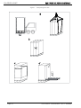
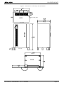
Fig. 4 - Dimensions of UPS rating 60 and 80kVA ...................................................................................... 20
Fig. 5 - Dimensions of UPS rating 100 and 120kVA .................................................................................. 21
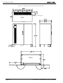
Fig. 6 - Dimensions of UPS ratings 160 and 200kVA ................................................................................ 22
Fig. 7 - Dimensions of UPS ratings 250, 300 and 400kVA ........................................................................ 23
Fig. 8 - Roof - 250/300/400kVA ................................................................................................................. 24
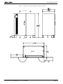
Fig. 9 - Dimensions of UPS rating 500kVA ................................................................................................ 25
Fig. 10 - Dimensions of UPS ratings 600/800kVA ..................................................................................... 26
Fig. 11 - Cubicle footprint - 60 - 120kVA.................................................................................................... 27
Fig. 12 - Cubicle footprint - 160 - 200kVA.................................................................................................. 28
Fig. 13 - Cubicle footprint - 250/300/400kVA............................................................................................. 29
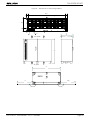
Fig. 14 - Cubicle footprint 500kVA............................................................................................................. 30
Fig. 15 - Cubicle footprint - 600/800kVA.................................................................................................... 31
Fig. 16 - Two mains supplies..................................................................................................................... 35
Fig. 17 - 60-80kVA UPS connections......................................................................................................... 36
Fig. 18 - 100kVA UPS connections............................................................................................................ 37
Fig. 19 - 120kVA UPS connections............................................................................................................ 38
Fig. 20 - 160-200kVA UPS connections..................................................................................................... 39
Fig. 21 - 250/300UPS connections ............................................................................................................ 40
Fig. 22 - 400kVA UPS connections............................................................................................................ 41
Fig. 23 - 500kVA UPS power connections ................................................................................................ 42
Fig. 24 - 600/800kVA power connections - Input cubicle .......................................................................... 43
Fig. 25 - 600/800kVA power connections - Output cubicle ....................................................................... 44
Fig. 26 - Output cubicle connection points................................................................................................ 45
Fig. 27 - Plaited power cables ................................................................................................................... 46
Fig. 28 - Installing the lexan power connection protective panels............................................................. 46
Fig. 29 - Battery connection diagram ........................................................................................................ 51
Fig. 30 - Dimensions of COC rating 400/800A .......................................................................................... 56
Fig. 31 - Dimensions of COC rating 1600A ............................................................................................... 57
Fig. 32 - Dimensions of COC rating 3200A ............................................................................................... 58
Fig. 33 - COC 400/800A ............................................................................................................................ 61
Fig. 34 - COC 1600A ................................................................................................................................. 62
Fig. 35 - COC 3200A ................................................................................................................................. 63
Fig. 36 - POB mounting location ............................................................................................................... 65
Fig. 37 - POB interconnection diagram ..................................................................................................... 66
Fig. 38 - Inserting the shielding clamp....................................................................................................... 66
Fig. 39 - Removing the shielding clamp .................................................................................................... 66
Fig. 40 - Connections and loop circuit (25-pin plug) for example 4-block system ..................................... 67
Fig. 41 - UPS On-line Double Conversion operation.................................................................................. 71
Fig. 42 - Overview UPS components ........................................................................................................ 74
Fig. 43 - Power flow in on-line operation................................................................................................... 75
Fig. 44 - Power flow in battery operation .................................................................................................. 75
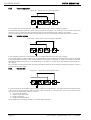
Fig. 45 - Power flow in reserve operation ................................................................................................. 76
Fig. 46 - Power flow in service bypass operation...................................................................................... 76
Fig. 47 - Power flow during battery test.................................................................................................... 76
Fig. 48 - Power flow in frequency converter operation ............................................................................. 77
Fig. 49 - Centralised parallel system electrical connections - 400/800A.................................................... 77
Fig. 50 - Centralised parallel system electrical connections - 1600/3200A................................................ 78
Fig. 51 - Centralised parallel system electrical connections ...................................................................... 79
Fig. 52 - Distributed parallel system electrical connections ...................................................................... 80
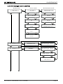
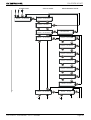
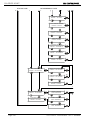
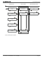
Fig. 53 - Control Panel ............................................................................................................................... 85
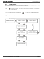
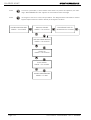
Fig. 54 - System block, main- and submenus ........................................................................................... 86
Fig. 55 - COC control panel ....................................................................................................................... 95
Fig. 56 - Connections for modular parallel system .................................................................................. 119
Fig. 57 - PPVis - page [3] Contacts .......................................................................................................... 138
Fig. 58 - Connectivity panel ..................................................................................................................... 141
Fig. 59 - Location of connectivity panel ................................................................................................... 141
User Handbook - 10H52168UM01
- rev. 5 - 05/2008
Page 7
CHLORIDE 90-NET
Page 8
User Handbook - 10H52168UM01
- rev. 5 - 05/2008
ABOUT THESE OPERATION INSTRUCTIONS
CHLORIDE 90-NET
1. ABOUT THESE OPERATION INSTRUCTIONS
Who are these operating instructions intended for?
These operating instructions are intended for use by qualified personnel involved in the transport, installation,
commissioning, maintenance and operation of the 90-NET devices.
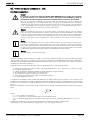
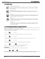
Symbols used
The following symbols are used in this handbook:
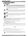
Danger
As defined by these operating instructions and the danger notices on the products. Failure
to observe the appropriate safety measures will result in death, severe injury or considerable damage to property.
Warning
As defined by these operating instructions and the warning notices on the products. Failure to carry out described operations or observe proper precautions may result in death,
severe injury or considerable damage to property.
Notice
This pictogram draws attention to important information about the product or part of the
operating instructions.
Indicates a step that must be carried out
Terms used
Maintenance bypass
The switch that allows maintenance work to be carried out without interrupting the supply to the load.
Electronic bypass
A thyristor switch which connects the load directly to mains in event of inverter overload; also referred to as
a static switch or static bypass.
Qualified personnel
Personnel who are familiar with the installation, assembly, commissioning and operation of the product and
are qualified to carry out the respective activities.
Display
An LCD display, providing information about the operating status of the UPS.
EC Declaration of Conformity
The 90-NET System (UPS device with battery cabinet) is in conformity with the protection and safety objectives of the following European directives:
2006/95/EC
Directive of the council for adaptation of the legal regulations of the member states regarding electrical equipment for use within specific voltage limits (superseding the 73/23/EC and successive amendments).
89/336/EC
Directive of the council for adaptation of the legal regulations of the member states regarding electromagnetic
compatibility, modified by directive 91/263/EC, 92/31/EC and 93/68/EC.
Conformity is established through compliance with the following standards:
·EN 62040-1-2
·EN 50091-2
·IEC/EN 62040-3
User Handbook - 10H52168UM01
- rev. 5 - 05/2008
Page 9
CHLORIDE 90-NET
Page 10
ABOUT THESE OPERATION INSTRUCTIONS
User Handbook - 10H52168UM01
- rev. 5 - 05/2008
SAFETY
CHLORIDE 90-NET
2. SAFETY
Intended use
This device serves as an uninterruptible power supply for connected loads.
It complies with all relevant safety regulations governing information technology equipment.
Notice
This UPS may only be installed in closed operating areas. If the area contains or if there is present in
the area, any equipment containing in excess of 25 litres of inflammable liquids, refer to HD
384.4.42 S1 A2, chapter 42 (corresponds to DIN VDE 0100, Part 420), it must be ensured that burning liquids or their combustion products cannot spread through the building.
Safety Notices
Carefully read the following safety notices!
Warning
Dangerous voltages are present within the device when in operation, failure to comply with the
warning notices may result in death, severe injury, or considerable damage to property. It is important to note, also, that when the EPO (Emergency Power Off) is in operation, i.e. the unit has been
automatically switched off due to some dangerous fault condition, battery power is still present
within the UPSThis device must be installed, connected, commissioned, maintained and repaired by
qualified personnel. These personnel must be familiar with all repair and maintenance tasks
described in these operating instructions. Error-free and safe operation of this device requires proper
transport, storage, placement, installation and connection, as well as careful operation and maintenance.
Danger
Mains over-voltage:this UPS must be protected against over-voltages deriving from the mains supply.The device was developed in accordance with the product normative EN 50091-2, which relates
to the IEC 1000-4-5. Over-voltages must be planned for in the power supply system, including those
caused by lightning strikes as well as those produced internally as the result of switching inductive
or capacitive loads, such as power transformers or capacitor banks, or as the result of short-circuit
shutdowns.
In addition to the warning notices given in the respective sections, pay particular attention
to the following notices:
• When selecting a location for the device and before operation, observe the notices
concerning environmental conditions.
• When disconnecting the mains voltage, the connected loads continue to be supplied with voltage by the battery, and return voltage is present at the input terminals of
the UPS.
• During thunderstorms, data transfer cables must not be connected or disconnected.
• Ensure that no objects (e.g. drilling chips, screws etc.) are left inside of the device.
Emergency measures
In order to conform to the European Standard EN62040-1-2 (par. 5.3) , a UPS must be fitted with an
Emergency Power Off device (E.P.O.) that can be used to shut down the unit completely in the event
of an emergency. 90-NET is equipped with a dedicated user input which is default configured to execute the EPO function. Refer to “Individual UPS signal connection information” on page 48 for
instructions on how to install an E.P.O. button on this UPS.
User Handbook - 10H52168UM01
- rev. 5 - 05/2008
Page 11
SAFETY
CHLORIDE 90-NET
In the event of an emergency, press the EPO button immediately in order to shut down the
entire system.
If, for any reason, the EPO fails to switch off the UPS, proceed as follows:
• Open the external mains separation device
• Switch off the load
• NEVER ATTEMPT TO OPEN OR CLOSE THE UPS BATTERY SWITCH UNDER
EMERGENCY CONDITIONS
• In case of fire, call the emergency personnel/fire brigade, who must put out any
flames using an extinguisher appropriate to the batteries in use
• NEVER ATTEMPT TO EXTINGUISH A FIRE USING WATER AS BATTERIES CARRY
LIVE VOLTAGE AT ALL TIMES
Danger Areas
For reasons of safety the Operator MUST NOT REMOVE the secondary access panel.
If, for any reason, it is necessary to remove this panel, the installation must be switched off
and de-energised, otherwise complete safety cannot be guaranteed.
When the UPS is closed, parts which carry voltage must not be touched. After removing the protective panels
or terminal field covering, the connection terminals and rails, as well as exposed metal parts and other components carrying dangerous voltages are no longer protected against accidental contact!
When working on an open UPS device, the corresponding safety measures must be observed. The following
danger is present even with disconnected UPS:
Danger
The UPS contains capacitors which continue to store energy for a period of time after the device has
been disconnected from the mains supplies and battery. This voltage (> 500 V DC) is present at battery terminals C+ and D-. For this reason, check that the UPS and the external mains separation
device are switched off and the battery fuses removed. Before continuing work, measure the voltage at the battery terminals and at the mains input filter and wait until this has dropped to 0 V. Failure to do this can lead to severe electrical shock and even death.
Warning
The UPS battery switch is equipped with an electro-mechanical interlock, however, we recommend
that YOU CHECK THAT THE POLARITY IS CORRECT!
Notice
90-NET has been designed for installation in TN-S and TN-C systems. Please contact your distributer
if you are uncertain about your installation.
For installation in permanent IT systems please contact CHLORIDE Technical Support.
Page 12
User Handbook - 10H52168UM01
- rev. 5 - 05/2008
EQUIPMENT DELIVERY AND STORAGE
CHLORIDE 90-NET
3. EQUIPMENT DELIVERY AND STORAGE
3.1. Transportation
Warning
Pay attention to the markings indicating the centre of gravity of the device. Use suitable means of
transportation and secure the UPS against tipping over when transporting. Improper transportation
can result in damage to the UPS and battery cabinet as well as injury to personnel.
All UPS cabinets are delivered on transport pallets:
• 60/80 kVA
Transport pallet 980 x 1000 mm (w x d). The pallet raises the UPS device by approx. 210 mm.
• 100/120 kVA
Transport pallet 1200 x 1000 mm (w x d). The pallet raises the UPS device by approx. 210
mm
• 160/200 kVA
Transport pallet 1595 x 1000 mm (w x d). The pallet raises the UPS device by approx. 200
mm.
• 250/300/400 kVA
Transport pallet 1795 x 1000 mm (w x d). The pallet raises the UPS device by approx. 200
mm.
• 500 kVA
Transport pallet 2200 x 1000 mm (w x d). The pallet raises the UPS device by approx. 200
mm.
• 600/800 kVA
Input cubicle: Transport pallets 1795 x 1000 mm (w x d). The pallet raises the UPS device by
approx. 200 mm.
Output cubicle: Transport pallets 1795 x 1000 mm (w x d). The pallet raises the UPS device
by approx. 200 mm
• COC 400/800 A
Transport pallet 1200 x 1010 mm (w x d). The pallet raises the UPS device by approx. 210
mm.
• COC 1600 A
Transport pallet 980 x 1010 mm (w x d). The pallet raises the UPS device by approx. 210 mm
• COC 3200 A
Transport pallet 1200 x 1010 mm (w x d). The pallet raises the UPS device by approx. 210
mm.
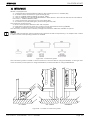
Transport the UPS and battery cabinets to the storage or installation site on the pallet in the
original packaging, using a suitable lifting truck or crane, (see Fig. 1 and Fig. 2), if a crane is
used, insert lifting beams to ensure the unit is not damaged (see step “a”).
When moving the 250/300/400 and 500kVA ratings it is possible to use two forklifts, inserting
one at each side.
In the case of the 250/300/400/600/800kVA ratings there are two central feet (see Fig. 13 - on
page 29 and Fig. 15 - on page 31) which may obstruct the forks. (See Table 1 on page 15).
In the case of the 500kVA there is a continuous foot in the middle of the cabinet (see Fig. 13 on page 29) which may obstruct the forks. (See Table 1 on page 15).
3.2. Storage
If the UPS and battery cabinets are not to be installed immediately, they may be kept in storage. Observe the
following:
• Store the UPS and battery cabinets in their original packaging.
• The storage conditions described in the appendix must be observed.
• Batteries must be recharged at least once every three months. If battery cabinets are to be stored for
longer then three months before installation, ensure that they are recharged regularly during this period.
• Pay attention to the times given for recharging the batteries. These values are given on a sticker on the
device or on the packaging.
User Handbook - 10H52168UM01
- rev. 5 - 05/2008
Page 13
CHLORIDE 90-NET
EQUIPMENT DELIVERY AND STORAGE
Figure 1 - Transporting the UPS
Page 14
User Handbook - 10H52168UM01
- rev. 5 - 05/2008
EQUIPMENT DELIVERY AND STORAGE
CHLORIDE 90-NET
Figure 2 - Width between forks
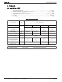
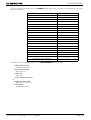
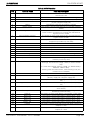
Table 1: Forklift clearance dimensions
UPS Model (kVA)
COC Ratings (A)
max
dimensions of
60/
80
100/
120
160/
200
250/300/
400
500
600/800a)
400/
800
1600
a (mm)
150
150
150
150
100b)
150
150
150
bc) (mm)
560
560
560
600
560
600
600
560
cd) (mm)
585
785
1160
1300
1600
(770 + 770)e)
1300
700
585
d (mm)
150
150
150
150
150
150
150
150
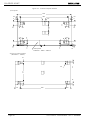
a) The 600/800 ratings consist of two cubicles, the measurements refer to the individual cubicles.
b) Note lower forklift clearance than for other ratings.
c) For 60 - 200kVA ratings pay attention to the centre foot when inserting the forks (see Fig. 11 - on
page 27.
For 250/300/400 and 500kVA ratings, two forklifts must be used, paying attention to the supports
under the centre of the unit when inserting the forks (see Fig. 13 - on page 29 and Fig. 14 - on
page 30).
d) For 250/300/400/500/600 and 800kVA ratings pay attention to the supports under the centre of
the unit when inserting the forks (see Fig. 13 - on page 29 and Fig. 14 - on page 30).
e) If at all possible, the UPS should be lifted by inserting the forks at the side (b); if it is necessary to
lift it by inserting the forks at the front or rear, open the front panels to avoid bending them.
When lifting from the front or rear, use adjustable width forks, or two forklifts - do not attempt to
lift using a single, fixed-width forklift.
User Handbook - 10H52168UM01
- rev. 5 - 05/2008
Page 15
CHLORIDE 90-NET
Page 16
EQUIPMENT DELIVERY AND STORAGE
User Handbook - 10H52168UM01
- rev. 5 - 05/2008
INSTALLATION PREPARATIONS
CHLORIDE 90-NET
4. INSTALLATION PREPARATIONS
4.1. Unpacking
Notice
The device should be unpacked at the installation site since the packaging provides additional protection during transportation
Unpack the device as follows:
• Check the UPS and battery cabinet for physical damage and in the event of problems, inform the forwarding agent and if necessary, your CHLORIDE agent.
• Check the nameplates on the UPS and battery cabinet against the delivery papers
and your order. The nameplate can be viewed with front door open. It is also attached
to the packaging.
• Loosen the fastening screws on the pallet.
• Slowly lift the cabinets from the pallet; depending on the weight 2 or 3 people
should be at hand (see Fig. 1 and Fig. 2).
• Keep the pallet for repackaging or transportation at a later time.
Dispose of the remaining packaging material in accordance with local regulations
4.2. Transporting without packaging materials
The cabinets can easily be moved to their final destinations with lifting devices.
Warning
Stones, or irregularities in the floor can block the fork lift. Moving the cabinets too quickly can damage them, causing them to fall over and injure personnel.
4.3. Selecting an installation site
Pay attention to the following conditions when selecting an installation site:
Notice
This UPS must only be installed in closed operating areas. If the area contains, or if there is present
in the area, any equipment containing in excess of 25 litres of inflammable fluids, refer to HD
384.4.42 S1 A2, chapter 42 (corresponds to DIN VDE 0100, Part 420), it must be ensured that burning fluids or their combustion products cannot spread through the building.
4.3.1.
Ambient temperature
The ambient temperature should be between 0°C and +40°C for UPS devices. For continuous operation at
temperatures up to a maximum of +50°C, the maximum load must be reduced by 12 % of the nominal load
per 5°C.
The ambient temperature should be between +15°C and +25°C for battery cabinets.
Be sure to provide sufficient cooling of the installation room so that the ambient temperature remains within the stated limits. The heat emission ratings of the UPS are given in the
Appendix. Be sure also to provide sufficient ventilation for the type of batteries used in the
UPS.
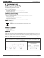
4.3.2.
Installation altitude
When operating the 90-NET UPS at altitudes above 1000m a.s.l., the load must be reduced in accordance
with Fig. 3. If the ambient temperature remains less than +30°C, no load reduction is necessary for altitudes
up to 2000 m.
User Handbook - 10H52168UM01
- rev. 5 - 05/2008
Page 17
INSTALLATION PREPARATIONS
CHLORIDE 90-NET
Figure 3 - Permissible load dependent on installation altitude
100
90
80
70
1000
4.3.3.
2000
3000
Floor
Be sure that the load carrying capacity of the floor is sufficient for the UPS and batteries. The floor must be
even and level.
4.3.4.
Environmental conditions
Avoid harmful environmental conditions such as:
• vibration
• dust
• corrosive atmospheres
• high humidity
4.3.5.
Space requirements
Provide the following minimum distances:
• minimum of 50 cm between the top of the cabinet and the roof
• no wall-distance if the cable is run through a double floor, otherwise the wall-distance must be at least
equal to the bending radius of the cables in use. The distance between covering parts and floor is 150
mm.
• no limitations on either side of the device
4.4. Placement
Danger
Whenever the devices are moved they must be secured against sideways tipping
Page 18
User Handbook - 10H52168UM01
- rev. 5 - 05/2008
INSTALLATION
CHLORIDE 90-NET
5. INSTALLATION
5.1. Installation data
•
•
•
•
•
•
•
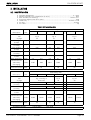
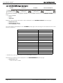
Ambient temperature .............................................................................................0 + 40°C
Relative humidity (w/o condensation @ 20°C).............................................................. 90%
Max. altitude (w/o derating) .............................................................................1000 m.a.s.l.
Protection degree (with doors open)............................................................................. IP20
Cable entry ....................................................................................................bottom or side
Air inlet ......................................................................................................................bottom
Air outlet..........................................................................................................................top
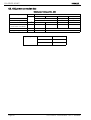
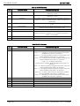
Table 2: UPS installation data
Description
U.M.
Dimensions
see:
on page
Net weight
kg
(6 step)
Net weight
kg
(12 step)
Floor loading
kg/m2
(6 step)
Floor loading
kg/m2
(12 step)
Nominal air flow m3/h
of fans
(kW)
Max. dissipation
(@nominal load
(kcal/h)
and battery
recharging)
Max. audible
noise level (@1m) dBA
Description
Dimensions
see:
on page
Net weight
(12 step)
Floor loading
(12 step)
U.M.
60
80
UPS Ratings kVA
100
120
Fig. 5
21
630±35
725±35
Fig. 6
22
1100±35
780±35
925±35
1011±35
1504±35
930
770
875
940
1330
1125
1230
1320
1800
2400
1200
4.4
5.8
6.8
8.1
10
12.6
3786
4990
5851
6969
8604
10842
62
250
300
64
Fig. 9
25
2575±35
1455
1640
1560
Nominal air flow m3/h
of fans
(kW)
Max. dissipation
(@nominal load
(kcal/h)
and battery
recharging)
Max. audible
noise level (@1m) dBA
3600
4800
6000
User Handbook - 10H52168UM01
65
UPS Ratings kVA
400
500
kg/m2
STANDARD FINISH:
200
Fig. 4
20
554±35
Fig. 7 and Fig. 8
23 and 24
1920±35
2155±35
kg
160
600
I/P
O/P
I/P
O/P
800
Fig. 10
26
2010±35
1955±35
1530
1570
11400
18.7
21.1
27.9
34.8
45.6
60.8
16086
18156
24006
29940
39230
52305
68
70
72
LIGHT GREY
RAL 7035
- rev. 5 - 05/2008
75
Page 19
INSTALLATION
CHLORIDE 90-NET
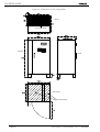
Figure 4 - Dimensions of UPS rating 60 and 80kVA
ROOF
Air outlet grids
Air outlet
Air inlet
BASE
Page 20
User Handbook - 10H52168UM01
- rev. 5 - 05/2008
INSTALLATION
CHLORIDE 90-NET
Figure 5 - Dimensions of UPS rating 100 and 120kVA
ROOF
Air outlet grids
Air outlet
Air inlet
BASE
User Handbook - 10H52168UM01
- rev. 5 - 05/2008
Page 21
INSTALLATION
CHLORIDE 90-NET
Figure 6 - Dimensions of UPS ratings 160 and 200kVA
Air outlet grids
ROOF
Air outlet
Air inlet
BASE
Page 22
User Handbook - 10H52168UM01
- rev. 5 - 05/2008
INSTALLATION
CHLORIDE 90-NET
Figure 7 - Dimensions of UPS ratings 250, 300 and 400kVA
Air outlet
Air inlet
BASE
User Handbook - 10H52168UM01
- rev. 5 - 05/2008
Page 23
INSTALLATION
CHLORIDE 90-NET
Figure 8 - Roof - 250/300/400kVA
250/300kVA
1470
=
247
491
250/300kVA
=
491
247
148.5
148.5
630
148.5
148.5
208
XT1
XT2
400kVA
1470
400kVA
=
Air outlet grids
=
630
208
XT1
Page 24
XT2
User Handbook - 10H52168UM01
- rev. 5 - 05/2008
INSTALLATION
CHLORIDE 90-NET
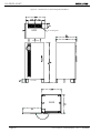
Figure 9 - Dimensions of UPS rating 500kVA
1010
=
=
Air outlet grids
9
630
ROOF
208
XT1
XT2
max
858
Air outlet
838
1780
Air inlet
2022
BASE
1010
1000
1010
User Handbook - 10H52168UM01
- rev. 5 - 05/2008
Page 25
INSTALLATION
CHLORIDE 90-NET
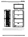
Figure 10 - Dimensions of UPS ratings 600/800kVA
1
1 - The busbars for interconnection with the output cubicle protrude beyond the width of the input cubicle
(which is supplied without a right side panel); the overall width of the UPS is equal to the width of the two
cubicles, installed side by side, plus 30 mm interconnection space = 3,25m.
2 - The external front panels (I/P cubicle left, and O/P cubicle right) can be opened through 180°, whereas
the internal front panels (I/P cubicle right, and O/P cubicle left) can only be opened through 135°.
Page 26
User Handbook - 10H52168UM01
- rev. 5 - 05/2008
INSTALLATION
CHLORIDE 90-NET
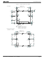
Figure 11 - Cubicle footprint - 60 - 120kVA
1) Footprint
60/80kVA = 822
100/120kVA = 1022
11
11
105
105
10
50
50
80
255
80
255
50
50
255
135
395
190
50
50
30
Gland plate.
60/80kVA = 586 x 92 mm
100kVA = 736 x 102 mm
120kVA = 736 x 116 mm
2) Floor mounting holes
(diameter = 12mm)
60/80kVA = 660
100/120kVA = 860
70
70
25
25
305
305
45
45
387
445
25
83
70
User Handbook - 10H52168UM01
- rev. 5 - 05/2008
70
Page 27
INSTALLATION
CHLORIDE 90-NET
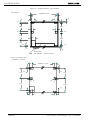
Figure 12 - Cubicle footprint - 160 - 200kVA
1) Footprint
160/200kVA = 1422
11
11
105
105
10
50
50
80
262.5
80
262.5
50
50
247.5
135
387.5
190
50
50
30
Gland plate
160/200kVA = 1100 x 134 mm
2) Floor mounting holes
(diameter = 12mm)
70
160/200kVA = 1260
70
25
25
312.5
312.5
45
45
379.5
437.5
25
83
70
Page 28
70
User Handbook - 10H52168UM01
- rev. 5 - 05/2008
INSTALLATION
CHLORIDE 90-NET
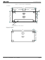
Figure 13 - Cubicle footprint - 250/300/400kVA
1) Footprint
1622
11
725
150
11
725
11
150
100
120
100
155
838
100
325
30
Gland plate
250/300/400KVA = 1290 x 156 mm
2) Floor mounting holes
(diameter = 12mm)
70
1460
58
684
User Handbook - 10H52168UM01
- rev. 5 - 05/2008
Page 29
INSTALLATION
CHLORIDE 90-NET
Figure 14 - Cubicle footprint 500kVA
1) Footprint
2022
100
100
1800
100
11
11
120
80
80
120
80
225
120
80
95
80
115
80
80
120
30
25
25
120
Gland plate
500KVA = 1800 x 140mm
80
2) Floor mounting holes
(diameter = 14mm)
50
30
ø14
615
55
50
155
Page 30
1690
155
User Handbook - 10H52168UM01
- rev. 5 - 05/2008
INSTALLATION
CHLORIDE 90-NET
Figure 15 - Cubicle footprint - 600/800kVA
BOTTOM VIEW
FRONT
FRONT
BOTTOM VIEW
BOTTOM VIEW
User Handbook - 10H52168UM01
FRONT
- rev. 5 - 05/2008
Page 31
INSTALLATION
CHLORIDE 90-NET
Page 32
User Handbook - 10H52168UM01
- rev. 5 - 05/2008
POWER AND SIGNAL CONNECTIONS
CHLORIDE 90-NET
6. POWER AND SIGNAL CONNECTIONS
6.1. Power connections
Danger
For reasons of safety the Operator MUST NOT REMOVE the secondary access panel.
If, for any reason, it is necessary to remove this panel, the installation must be
switched off and de-energised, otherwise complete safety cannot be guaranteed.
The UPS is connected to 400/230 V three-phase mains; DC voltages above 500 V are additionally
present in the battery circuit. Installation must only be carried out by qualified personnel in accordance
with these operating instructions and the regulations of the local electricity provider. The UPS devices
create a large leakage current; therefore connect to ground prior to commissioning.Improper connection can damage the device and lead to injuries and even death.
Danger
Mains overvoltage:this UPS must be protected against overvoltages deriving from the feeding
mains.The device was developed in accordance with the product normative EN 50091-2, which relates
to the IEC 1000-4-5. Overvoltages must be planned for in the power supply system, including those
caused by lightning strikes as well as those produced internally as the result of switching inductive or
capacitive loads, such as power transformers or capacitor banks or as the result of short-circuit shutdowns.
Notice
This device is not equipped with its own mains separation device. You are, therefore, required to provide a mains separation device at the installation site. It must be installed near the device and labelled
as the mains separation device for the UPS.These mains separation devices and all upstream switchs
must be provided with a warning plate on which the following is stated: "ISOLATE THE UNINTERRUPTIBLE POWER SYSTEM (UPS) PRIOR TO OPERATING ON THIS CIRCUIT".
Notice
QS2 and QS4 are used for disconnecting.
The following table gives indications of cable cross sections and fuse ratings. For mains and load connection
use exclusively the screws provided to ensure that the specified air and leakage distances are maintained.
The feeds for the rectifier or bypass and service bypass can be supplied from either separate (optional, see
Fig. 14) or the same mains supply. The load is connected to the load connection.
Cable dimensions are purely indicative. They are applicable only in the following cases:
• copper wire with PVC insulation (max. operating temperature = 70° C, multi-core - to 35 mm², singlecore - greater than 35 mm²),
• cables are fitted in separate conduits for each line (input, output, battery),
• air temperature in conduits does not exceed 30° C,
• the maximum number of cables per conduit is 4.
• when laying in channels or for electric installation conduits
• for cable lengths up to 30 m
If conditions are different refer to DIN VDE 0298 part 4. When selecting the conductor cross section, local
conditions and standards, as well as application-specific voltage drops due to cable lengths, must be taken
into account. If the UPS is to supply predominantly non-linear loads, multiply the quoted cross section for PEN
by 1.6.
Recommended earth wire sizes are purely indicative; they may be calculated exactly using the following formula:
2
s =
(I ⋅ t)
--------------k
where:
• s = min. earth wire size (mm)
• I².t = nominal I².t of the protection device (on the Mains input)
• k = coefficient depending on insulating material (for PVC, max. operating temperature = 70° C, k =
143)
In different conditions, wire size can be calculated in accordance with IEC standard 287.
If the length of the cables causes a voltage drop > 3%, use a larger wire size.
Data provided in the table concerning selectivity of the load fuses apply for activated electronic bypass.
In order to guarantee safe working conditions, ensure all voltage sources are isolated before carrying
out the power connections. The UPS battery switch is equipped with an electro-mechanical interlock,
however, we recommend that YOU CHECK THAT THE POLARITY IS CORRECT!!
User Handbook - 10H52168UM01
- rev. 5 - 05/2008
Page 33
POWER AND SIGNAL CONNECTIONS
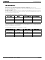
CHLORIDE 90-NET
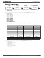
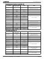
Table 3: Cable dimensions and fuse ratings
Description
UM
60
See
on page
80
Fig. 17
36
Max. Imains I/P @ 400V (1)
Recommended wire size (2) (3)
Wire socket screw size
Nom. Iout/res @ 400V
(1) (5)
A
120
160
mm2 50 (2x16) 70 (2x25)
mm
M8x25
A
87
116
Recommended wire size (4)
mm2
Wire socket screw size
Ibatt I/P (discharging @1.8V/cell)
mm
A
35
(2x10)
145
Wire socket screw size
Recommended wire size for
earth conductor
Wire socket screw size
mm
mm2
mm
M8x25
Description
UM
250
See
on page
300
Fig. 21
40
Max. Imains I/P @ 400V (1)
A
495
592
Recommended wire size (2) (3)
mm2
2x120
2x180
(3x120)
Wire socket screw size
mm
A
360
435
Recommended wire size (4)
mm2
2x95
2x120
(3x70)
Wire socket screw size
Ibatt I/P (discharging @1.8V/cell)
mm
A
493
591
2x120
(2x180)
3x120
(2x180)
120
2x95
Nom. Iout/res @ 400V
(1) (5)
Recommended wire size
mm
Wire socket screw size
Recommended wire size for
earth conductor
Wire socket screw size
mm
2
mm2
mm
Tigthening torque
317
397
2x70
2x95
145
M10x30
174
232
290
120
(2x50)
70
95
(2x25)
(2x35)
M8x25
35
200
Fig. 20
39
120
70
(2x25)
mm
160
95
50
(2x16)
M8x25
193
Recommended wire size
2
Rating (kVA)
100
120
Fig. 18
37
200
240
95
(2x35)
240
289
2x50
2x70
M10x30
382
478
2x70
3x50
(3x35)
(4x35)
M10x30
70
95
50
2x120
(3x70)
120
M10x30
Rating (kVA)
400
500
Fig. 22
Fig. 23
41
42
790
980
600
800
Fig. 24 and Fig. 25
43 and 44
1154
1600
4x120
5x120
(2x240)
(3x240)
M12x40
580
725
3x240
4x240
870
1160
2x180
4x120
(3x120)
(2x240)
M12x40
788
985
1170
3x240
4x120
5x120
3x240
(2x240)
(3x240)
M12x40
2x120
3x120
(240)
(2x240)
M12x40
4x240
Screw size
Nm (+/-10%)
M8
20
M10
39
M12
68
1570
4x120
(2x240)
(1) For nominal voltage of 380V, multiply current value by 1.05; for 415V, multiply by 0.95.
(2) With cable lug according to DIN46235.
(3) When using the cable dimensions indicated in brackets a support rail shall be installed by the customer. The support rail supplied with the UPS must be removed.
(4) For non-linear loads, the neutral cable dimension must be 1.6 times the recommended dimension.
(5) The Reserve Input must be supplied by a three-phase plus neutral system.
Page 34
User Handbook - 10H52168UM01
- rev. 5 - 05/2008
POWER AND SIGNAL CONNECTIONS
CHLORIDE 90-NET
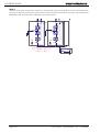
6.2. Cable lengths
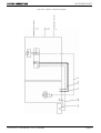
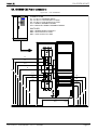
Figure 16 - Two mains supplies
Mains 2L1
Mains 1
L1
L2
L3
L2
L3
N
N
PE
N
PE
N
U
D-
V
W
PE
Rectifier
connection
U1
V1
W1
Reserve
connection
C+
Battery
U2
V2
W2
N
Load
For calculating the cable lengths, note the cable guide appropriate for your installation, either from behind,
from above or through an installation-side double bottom.
Carry out the mains connection as follows:
• Open the front door of the UPS.
• Remove the protective screen in front of the connection terminals.
• Check whether your UPS is fitted for one or two mains supplies and prepare the connection according to the wiring diagram Fig. 14. The connections C+ and D- are located
in the input connection terminal field.
Notice
For modular, parallel systems in which an additional output switch is installed for each UPS, the state
of each individual switch, connected in series with the UPS output switch (QS4), must be monitored
in order to prevent the entire load from being switched to a single UPS.
After being setup in its final location, make the following connections to the UPS:
• Make the ground connections (PE).
• Establish the mains and load connections.
• Remount the cable-entry cover and terminal fields.
• Provide physical support for the ground, mains and load connections.
If UPS is supplied from one mains only:
• Connect the mains supply cables to the UPS terminals U1, V1, W1, N. The following jumpers must be
fixed between the terminals: U1-U2, V1-V2, W1-W2 and N1-N2.
If UPS is supplied from two mains:
• Connect the mains 1 supply cables to the UPS terminals U1, V1, W1, N1.
• Connect the mains 2 supply cables to the UPS terminals U2, V2, W2, N2.
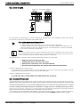
6.3. Backfeed Protection
This feature prevents any potential risk of electric shock at the UPS bypass input AC terminals in the event of
a Bypass static switch SCR failure. The control circuit includes a contact, that the customer can use to activate
an external isolating device, such as an electromagnetic relay, which will disconnect the bypass mains supply
to the UPS when a backfeed is detected. The backfeed protection contacts are available at pins 3, 4, and 5 of
XT1 (see “Individual UPS signal connection information” on page 48.) Pin 3 is normally closed (NC) with respect to pin 5 (Common), while pin 4 is normally open (NO). CHLORIDE recommends connecting the device
signal connections between the Normally Closed and Common contacts.
In compliance with the Standard IEC/EN 62040-1, the external isolating device, which must be an air-gap isolator, in accordance with clause 5.1.4 of the aforementioned Standard, IS NOT supplied with the UPS.
User Handbook - 10H52168UM01
- rev. 5 - 05/2008
Page 35
POWER AND SIGNAL CONNECTIONS
CHLORIDE 90-NET
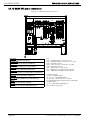
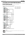
6.4. 60-80kVA UPS power connections
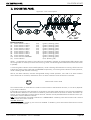
Figure 17 - 60-80kVA UPS connections
XS1
C+
D-
WARNING
ENSURE CORRECT POLARITY!
ATTENZIONE
VERIFICARE LA POLARITA’ CORRETTA!
ATTENTION
VEILLER AU RESPECT DE LA POLARITÉ!
ACHTUNG
KORREKTE POLUNG SICHERSTELLEN!
ATENCIÓN
COMPROBAR QUE LA POLARIDAD ES CORRECTA!
ATENÇÃO
GARANTA A POLARIDADE CORRECTA!
ВНИМАНИЕ
ОБЕСПЕЧИТЬ ПРАВИЛЬНУЮ ПОЛЯРНОСТЬ!
DİKKAT
KUTUPSALLIĞI GARANTİ EDİNİZ!
UWAGA
SPRAWDZIĆ WŁAŚCIWĄ BIEGUNOWOŚĆ!
Page 36
KEY
QS1 = MAINS INPUT switch (U, V, W)
QS2 = RESERVE INPUT switch (U1, V1, W1)
QS3 = BYPASS switch
QS4 = UPS OUTPUT switch (U2, V2, W2)
QS9 = BATTERY switch
XS1 = EASY/LIFE power socket
XT1 = REMOTE ALARMS terminal board
XT2 = REMOTE ALARMS terminal board
CONNECTIONS
U, V, W = MAINS INPUT
U1, V1, W1 = RESERVE INPUT
U2, V2, W2 = UPS OUTPUT to LOAD
N = RESERVE INPUT AND OUTPUT NEUTRAL
CONNECTION
C+, D- = BATTERY TERMINALS
PE = EARTH connection
User Handbook - 10H52168UM01
- rev. 5 - 05/2008
POWER AND SIGNAL CONNECTIONS
CHLORIDE 90-NET
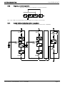
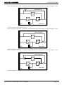
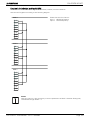
6.5. 100-120kVA UPS power connections
Figure 18 - 100kVA UPS connections
XS1
C+
D-
WARNING
ENSURE CORRECT POLARITY!
ATTENZIONE
VERIFICARE LA POLARITA’ CORRETTA!
ATTENTION
VEILLER AU RESPECT DE LA POLARITÉ!
ACHTUNG
KORREKTE POLUNG SICHERSTELLEN!
ATENCIÓN
COMPROBAR QUE LA POLARIDAD ES CORRECTA!
ATENÇÃO
GARANTA A POLARIDADE CORRECTA!
ВНИМАНИЕ
ОБЕСПЕЧИТЬ ПРАВИЛЬНУЮ ПОЛЯРНОСТЬ!
DİKKAT
KUTUPSALLIĞI GARANTİ EDİNİZ!
UWAGA
SPRAWDZIĆ WŁAŚCIWĄ BIEGUNOWOŚĆ!
User Handbook - 10H52168UM01
- rev. 5 - 05/2008
KEY
QS1 = MAINS INPUT switch (U, V, W)
QS2 = RESERVE INPUT switch (U1, V1, W1)
QS3 = BYPASS switch
QS4 = UPS OUTPUT switch (U2, V2, W2)
QS9 = BATTERY switch
XS1 = Power socket
XT1 = REMOTE ALARMS terminal board
XT2 = REMOTE ALARMS terminal board
CONNECTIONS
U, V, W = MAINS INPUT
U1, V1, W1 = RESERVE INPUT
U2, V2, W2 = UPS OUTPUT to LOAD
N = RESERVE INPUT AND OUTPUT NEUTRAL
CONNECTION
C+, D- = BATTERY TERMINALS
PE = EARTH connection
Page 37
POWER AND SIGNAL CONNECTIONS
CHLORIDE 90-NET
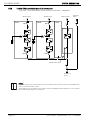
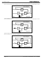
Figure 19 - 120kVA UPS connections
XS1
C+
D-
WARNING
ENSURE CORRECT POLARITY!
ATTENZIONE
VERIFICARE LA POLARITA’ CORRETTA!
ATTENTION
VEILLER AU RESPECT DE LA POLARITÉ!
ACHTUNG
KORREKTE POLUNG SICHERSTELLEN!
ATENCIÓN
COMPROBAR QUE LA POLARIDAD ES CORRECTA!
ATENÇÃO
GARANTA A POLARIDADE CORRECTA!
ВНИМАНИЕ
ОБЕСПЕЧИТЬ ПРАВИЛЬНУЮ ПОЛЯРНОСТЬ!
DİKKAT
KUTUPSALLIĞI GARANTİ EDİNİZ!
UWAGA
SPRAWDZIĆ WŁAŚCIWĄ BIEGUNOWOŚĆ!
Page 38
KEY
QS1 = MAINS INPUT switch (U, V, W)
QS2 = RESERVE INPUT switch (U1, V1, W1)
QS3 = BYPASS switch
QS4 = UPS OUTPUT switch (U2, V2, W2)
QS9 = BATTERY switch
XS1 = Power socket
XT1 = REMOTE ALARMS terminal board
XT2 = REMOTE ALARMS terminal board
CONNECTIONS
U, V, W = MAINS INPUT
U1, V1, W1 = RESERVE INPUT
U2, V2, W2 = UPS OUTPUT to LOAD
N = RESERVE INPUT AND OUTPUT NEUTRAL
CONNECTION
C+, D- = BATTERY TERMINALS
PE = EARTH connection
User Handbook - 10H52168UM01
- rev. 5 - 05/2008
POWER AND SIGNAL CONNECTIONS
CHLORIDE 90-NET
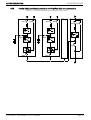
6.6. 160-200kVA power connections
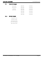
Figure 20 - 160-200kVA UPS connections
XS1
C+
D-
WARNING
ENSURE CORRECT POLARITY!
ATTENZIONE
VERIFICARE LA POLARITA’ CORRETTA!
ATTENTION
VEILLER AU RESPECT DE LA POLARITÉ!
ACHTUNG
KORREKTE POLUNG SICHERSTELLEN!
ATENCIÓN
COMPROBAR QUE LA POLARIDAD ES CORRECTA!
ATENÇÃO
GARANTA A POLARIDADE CORRECTA!
ВНИМАНИЕ
ОБЕСПЕЧИТЬ ПРАВИЛЬНУЮ ПОЛЯРНОСТЬ!
DİKKAT
KUTUPSALLIĞI GARANTİ EDİNİZ!
UWAGA
SPRAWDZIĆ WŁAŚCIWĄ BIEGUNOWOŚĆ!
User Handbook - 10H52168UM01
- rev. 5 - 05/2008
KEY
QS1 = MAINS INPUT switch (U, V, W)
QS2 = RESERVE INPUT switch (U1, V1, W1)
QS3 = BYPASS switch
QS4 = UPS OUTPUT switch (U2, V2, W2)
QS9 = BATTERY switch
XS1 = Power socket
XT1 = REMOTE ALARMS terminal board
XT2 = REMOTE ALARMS terminal board
CONNECTIONS
U, V, W = MAINS INPUT
U1, V1, W1 = RESERVE INPUT
U2, V2, W2 = UPS OUTPUT to LOAD
N = RESERVE INPUT AND OUTPUT NEUTRAL
CONNECTION
C+, D- = BATTERY TERMINALS
PE = EARTH connection
Page 39
POWER AND SIGNAL CONNECTIONS
CHLORIDE 90-NET
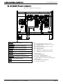
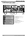
6.7. 250/300kVA UPS power connections
Figure 21 - 250/300UPS connections
XS1
WARNING
ENSURE CORRECT POLARITY!
ATTENZIONE
VERIFICARE LA POLARITA’ CORRETTA!
ATTENTION
VEILLER AU RESPECT DE LA POLARITÉ!
ACHTUNG
KORREKTE POLUNG SICHERSTELLEN!
ATENCIÓN
COMPROBAR QUE LA POLARIDAD ES CORRECTA!
ATENÇÃO
GARANTA A POLARIDADE CORRECTA!
ВНИМАНИЕ
ОБЕСПЕЧИТЬ ПРАВИЛЬНУЮ ПОЛЯРНОСТЬ!
DİKKAT
KUTUPSALLIĞI GARANTİ EDİNİZ!
UWAGA
SPRAWDZIĆ WŁAŚCIWĄ BIEGUNOWOŚĆ!
KEY
QS1 = MAINS INPUT switch (U, V, W)
QS2 = RESERVE INPUT switch (U1, V1, W1)
QS3 = BYPASS switch
QS4 = UPS OUTPUT switch (U2, V2, W2)
QS9 = BATTERY switch
XS1 = EASY/LIFE power socket
CONNECTIONS
U, V, W = MAINS INPUT
U1, V1, W1 = RESERVE INPUT
U2, V2, W2 = UPS OUTPUT to LOAD
N = RESERVE INPUT AND OUTPUT
NEUTRAL CONNECTION
C+, D- = BATTERY TERMINALS
PE = EARTH connection
D
O
Ğ
R
U
Page 40
User Handbook - 10H52168UM01
- rev. 5 - 05/2008
POWER AND SIGNAL CONNECTIONS
CHLORIDE 90-NET
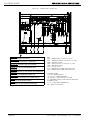
6.8. 400kVA UPS power connections
Figure 22 - 400kVA UPS connections
XS1
This label is applied on the inside left panel
WARNING
ENSURE CORRECT POLARITY!
ATTENZIONE
VERIFICARE LA POLARITA’ CORRETTA!
ATTENTION
VEILLER AU RESPECT DE LA POLARITÉ!
ACHTUNG
KORREKTE POLUNG SICHERSTELLEN!
ATENCIÓN
COMPROBAR QUE LA POLARIDAD ES CORRECTA!
ATENÇÃO
GARANTA A POLARIDADE CORRECTA!
ВНИМАНИЕ
ОБЕСПЕЧИТЬ ПРАВИЛЬНУЮ ПОЛЯРНОСТЬ!
DİKKAT
KUTUPSALLIĞI GARANTİ EDİNİZ!
UWAGA
SPRAWDZIĆ WŁAŚCIWĄ BIEGUNOWOŚĆ!
User Handbook - 10H52168UM01
- rev. 5 - 05/2008
KEY
QS1 = MAINS INPUT switch (U, V, W)
QS2 = RESERVE INPUT switch (U1, V1, W1)
QS3 = BYPASS switch
QS4 = UPS OUTPUT switch (U2, V2, W2)
QS9 = BATTERY switch
XS1 = EASY/LIFE power socket
CONNECTIONS
U, V, W = MAINS INPUT
U1, V1, W1 = RESERVE INPUT
U2, V2, W2 = UPS OUTPUT to LOAD
N = RESERVE INPUT AND OUTPUT NEUTRAL
CONNECTION
C+, D- = BATTERY TERMINALS
PE = EARTH connection
Page 41
POWER AND SIGNAL CONNECTIONS
CHLORIDE 90-NET
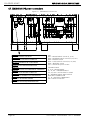
6.9. 500kVA UPS power and signal connections
Figure 23 - 500kVA UPS power connections
XS1
WARNING
ENSURE CORRECT POLARITY!
ATTENZIONE
VERIFICARE LA POLARITA’ CORRETTA!
ATTENTION
VEILLER AU RESPECT DE LA POLARITÉ!
ACHTUNG
KORREKTE POLUNG SICHERSTELLEN!
ATENCIÓN
COMPROBAR QUE LA POLARIDAD ES CORRECTA!
ATENÇÃO
GARANTA A POLARIDADE CORRECTA!
ВНИМАНИЕ
ОБЕСПЕЧИТЬ ПРАВИЛЬНУЮ ПОЛЯРНОСТЬ!
DİKKAT
KUTUPSALLIĞI GARANTİ EDİNİZ!
UWAGA
SPRAWDZIĆ WŁAŚCIWĄ BIEGUNOWOŚĆ!
Page 42
KEY
QS1 = MAINS INPUT switch (U, V, W)
QS2 = RESERVE INPUT switch (U1, V1, W1)
QS3 = BYPASS switch
QS4 = UPS OUTPUT switch (U2, V2, W2)
QS9 = BATTERY switch
XS1 = Power socket
CONNECTIONS
U, V, W = MAINS INPUT
U1, V1, W1 = RESERVE INPUT
U2, V2, W2 = UPS OUTPUT to LOAD
N = RESERVE INPUT AND OUTPUT NEUTRAL
CONNECTION
C+, D- = BATTERY TERMINALS
PE = EARTH connection
User Handbook - 10H52168UM01
- rev. 5 - 05/2008
POWER AND SIGNAL CONNECTIONS
CHLORIDE 90-NET
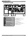
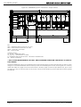
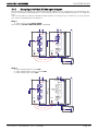
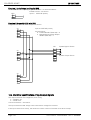
6.10. 600/800kVA power and signal connections
Figure 24 - 600/800kVA power connections - Input cubicle
KEY
QS1 = MAINS INPUT switch (U, V, W)
QS9 = BATTERY switch
CONNECTIONS
U, V, W = MAINS INPUT
C+, D- = BATTERY TERMINALS
User Handbook - 10H52168UM01
- rev. 5 - 05/2008
WARNING
ENSURE CORRECT POLARITY!
ATTENZIONE
VERIFICARE LA POLARITA’ CORRETTA!
ATTENTION
VEILLER AU RESPECT DE LA POLARITÉ!
ACHTUNG
KORREKTE POLUNG SICHERSTELLEN!
ATENCIÓN
COMPROBAR QUE LA POLARIDAD ES CORRECTA!
ATENÇÃO
GARANTA A POLARIDADE CORRECTA!
ВНИМАНИЕ
ОБЕСПЕЧИТЬ ПРАВИЛЬНУЮ ПОЛЯРНОСТЬ!
DİKKAT
KUTUPSALLIĞI GARANTİ EDİNİZ!
UWAGA
SPRAWDZIĆ WŁAŚCIWĄ BIEGUNOWOŚĆ!
Page 43
POWER AND SIGNAL CONNECTIONS
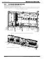
CHLORIDE 90-NET
Figure 25 - 600/800kVA power connections - Output cubicle
XS1
KEY
QS2 = RESERVE INPUT switch (U1, V1, W1)
QS4 = UPS OUTPUT switch (U2, V2, W2)
QS14 = NEUTRAL switch (N)*
XS1 = Power socket
CONNECTIONS
U1, V1, W1 = RESERVE INPUT
U2, V2, W2 = UPS OUTPUT to LOAD
N = RESERVE INPUT AND OUTPUT - NEUTRAL CONNECTION
PE = EARTH connection
* QS14 IS FOR MAINTENANCE USE ONLY, UNAUTHORISED OPERATION CAN RESULT IN LOSS OF
LOAD SUPPLY.
The 600 and 800kVA ratings are supplied without the manual bypass switch (corresponding to QS3 on other
ratings).It is recommended that the Customer provide an external Bypass switch, ensuring that it is correctly
rated (see Table 3 on page 34 for more information). Auxiliary signal contacts are provided at XT1, pins 11 and
12 (see Fig. 6.12), so that the status of the switch can be monitored during normal operation and the guided
procedures.
Page 44
User Handbook - 10H52168UM01
- rev. 5 - 05/2008
POWER AND SIGNAL CONNECTIONS
6.10.1.
CHLORIDE 90-NET
600/800kVA input and output cubicle interconnections.
• Place the input and output cabinets side by side (input cabinet on the left).
• Using M8 x 30 hexagonal bolts, secure the three points indicated by the letter “A” (on the output cubicle - see Fig. 26) to the corresponding points on the input cubicle.
• Using M6 x 16 hexagonal bolts, secure the point indicated by the letter “B” (on the output cubicle see Fig. 26) to the corresponding point on the input cubicle.
• Using M8 x 50 hexagonal bolts, connect the input and output feet together, see points indicated by
the letter “C”(see Fig. 26)
• Using M8 x 25 hexagonal bolts, connect the Inverter + and - busbars, indicated by the letter “D” (on
the output cubicle - see Fig. 26) to the corresponding rectifier module busbars on the input cabinet (see
also Fig. 26)
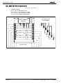
Figure 26 - Output cubicle connection points
User Handbook - 10H52168UM01
- rev. 5 - 05/2008
Page 45
POWER AND SIGNAL CONNECTIONS
CHLORIDE 90-NET
6.10.2.
Connecting the braided Copper power cables
Remove the input cubicle right safety panel.
Remove the output cubicle left and right safety panels.
Remove the grid at the bottom of the switch area.
Connected the braided power cables from the input cubicle to the transformer TM2 terminals, indicated by
the letter “G” (see Fig. 27), securing them at cable clamps “E”
, and routing them along the path marked “F”.
Figure 27 - Plaited power cables
Figure 28 - Installing the lexan power connection protective panels
A
A
A
A
A
A
A) material supplied loose - to be mounted
AA
A
A
A
A
Page 46
User Handbook - 10H52168UM01
- rev. 5 - 05/2008
POWER AND SIGNAL CONNECTIONS
CHLORIDE 90-NET
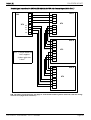
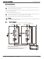
6.11. Signal connections
All signal cables (ribbon cables, shielded cables etc.) are already connected in the input cabinet. Once the
input and output cabinets have been connected together, the signal cables must be connected to their corresponding points in the output cubicle:
(1) Connect the flat cables to:
• Inverter Static Switch Firing board AP43 - 2K
• Inverter Static Switch Firing board AP43 - 3K
• Reserve Static Switch Firing board AP44 - 2K
• Driver D board AP45 - 1K
• Driver D board AP45 - 2K
• Driver D board AP46 - 1K
• Driver D board AP46 - 2K
• Driver D board AP47 - 1K
• Driver D board AP47 - 2K
(2) Connect the two cables from the output cubicle to AP50 X101 and X102 in the input cubicle.
(3) Connect the X20 connectors together.
(4) Connect the X9 connectors together.
Replace the switch area grid and the input and output safety panels.
User Handbook - 10H52168UM01
- rev. 5 - 05/2008
Page 47
POWER AND SIGNAL CONNECTIONS
CHLORIDE 90-NET
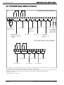
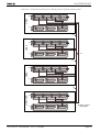
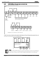
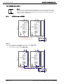
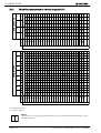
6.12. Individual UPS signal connection information
STANDARD CONFIGURATION
XT1
0
1
2
3
4
5
6
7
8
9
User Output 1 Default configured as
Backfeed Protection
Contacts
13
14
User Input 1
15
16
17
18
User Input 4
Auxiliary Bypass
Contacts 600/800kVA
ratings only
User Output 2
Battery temp.
sensor contact
12
11
10
19
20 100 200
User Input 3
Q100/Q200 SYNC. (MBSM)
option fuses 380V present!
User Input 5 Default
configured as
EPO
User Input 2
WITH ADDITIONAL 2nd I/O BOARD
30
31
32
33
34
35
User Output 4
User Output 3
36
37
38
39
40
User Output 8
User Output 6
41
42
43
User Output 9
User Output 7
The contacts XT1/17-18 are used for directly switching off the inverter and are located in the connection area
of the input cabinet above QS9 at the right of the power connections.
Terminals XT1.17 and XT1.18 are connected by a jumper when shipped. When setting up an external EPO
switch, the jumper must be removed. The jumper must satisfy the following requirements:
- length: max. 50 m
- cross section:min. 0.75 mm²
Page 48
User Handbook - 10H52168UM01
- rev. 5 - 05/2008
BATTERY CONNECTIONS
CHLORIDE 90-NET
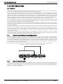
7. BATTERY CONNECTIONS
Before connecting the batteries, please read the Battery Manual (10H52168BM00), and the notice and
warning label on the UPS or battery cabinet.
Warning
Battery fuses are shipped together with the UPS and the battery cabinets. These should only be
installed during commissioning. If the battery fuses are inserted beforehand, the built-in intermediate
circuit capacitors can explode and damage the UPS.
Warning
In the event of malfunction, voltage may be present on the shelves or chassis of the battery cabinet
Notice
If externally supplied batteries are used, you must ensure that the applicable EC directives are met
and declare conformity. The UPS parameters must still be those of the service software and an all-pole
disconnecting device and fuses must be fitted in accordance with Table 5, page 53.
When dimensioning your battery cabling, special attention must be paid to the options for connection
to the +/- terminals as per Table 5, page 53. Also note the information regarding special settings provided in the appendix.
The battery cabinet may be installed directly to the right of the UPS.
Notice for alternative instalation
With enhanced battery management, the distance between the UPS and battery cabinet must not
exceed 20 meters. The connection line for the battery measurement module must be installed so that
it is properly grounded and so that there is no risk of accidental contact or short circuits. The isolation
is to be dimensioned for a rated voltage of 400 V.
Connect the batteries as follows:
• All switches must be in the "OFF" position.
• Check that the battery fuses are not inserted and, if third-party batteries are used, that the external
battery switch is open.
• Make the ground connections (PE).
• Connect the batteries with cables according to Table 5 to terminals C+ (positive pole) and D- (negative pole). The battery connection terminals are located on the left hand side of the UPS cubicle (see
figures 17 to 23.
• Connect the other end of the battery connection line to the battery cabinet or cubicle. The UPS battery switch is equipped with an electro-mechanical interlock, however, we recommend that YOU
CHECK THAT THE POLARITY IS CORRECT!
• Connect the temperature sensor cable to terminals XT1 - 0, 1 and 2 and to the battery cabinet or
cubicle.
The UPS battery switch is equipped with an electro-mechanical interlock, however, before the
system starts, we recommend that YOU CHECK THAT THE POLARITY IS CORRECT! Wrong
connections can damage the system and endanger operator safety.
User Handbook - 10H52168UM01
- rev. 5 - 05/2008
Page 49
BATTERY CONNECTIONS
CHLORIDE 90-NET
7.1. Battery cabinet connections
All connections listed in the following table are illustrated in Fig. 29
Table 4: UPS - battery connections
Cable
No.
Cable designation
Use
UPS connection
Terminal
Battery cabinet
connection
Cable
colour
Terminal
1.1
Supplied by battery
provider
Power cable
C+
+
1.2
Supplied by battery
provider
Power cable
D-
-
2.1
To be supplied by
customer
PE
PE
2.2
To be supplied by
customer
PE
gr/yl
PE
3
Temperature
sensor
XT1.1
brown
X1.1
3
Temperature
sensor
XT1.2
white
X1.2
3
Temperature
sensor
XT1.0
shield
Page 50
User Handbook - 10H52168UM01
- rev. 5 - 05/2008
BATTERY CONNECTIONS
CHLORIDE 90-NET
User Handbook - 10H52168UM01
- rev. 5 - 05/2008
Temperature sensors
3
PE
2.1
2.2
Power cables
1.1
1.2
Figure 29 - Battery connection diagram
Page 51
BATTERY CONNECTIONS
CHLORIDE 90-NET
7.1.1.
Handling the batteries
Warning
Batteries are a potential source of danger due to their electrical charge and chemical composition. Therefore, observe the battery handling instructions of the manufacturer. These
can usually be found in the material which accompanies the shipment.
7.1.2.
Recharging batteries
Notice
When recharging, observe the instructions on the packaging.
7.1.3.
Exchanging batteries
Notice
Before exchanging batteries, both the batteries in the battery cabinet, as well as those to
be installed must be fully charged.
7.1.4.
Connecting batteries
Warning
The UPS battery switch is equipped with an electro-mechanical interlock, however, we recommend that YOU CHECK THAT THE POLARITY IS CORRECT!
If the battery was disconnected and is to be reconnected, the battery isolator may only be reconnected after you have made certain that voltage with the correct polarity is present in the
intermediate circuit. If the battery is connected to the intermediate circuit while the circuit is
de-energised or with incorrect polarity, the intermediate-circuit capacitors could explode!
7.1.5.
Stripping down, repackaging
Danger
The UPS contains capacitors which continue to store energy for a period of time after the device has been disconnected from the mains supply and battery. This voltage (> 500 V DC) is
present at the battery terminals C+ and D-. Before stripping down, check that the UPS and
the external mains separation device are switched off and the battery fuses removed.
Measure the voltage at the battery terminals and wait until the voltage has dropped to 0 V or
wait at least five minutes. Failure to do this can lead to severe electrical shock and even death
Strip down the UPS in the reverse order of that described in the previous sections. Use the
original packaging if possible when repackaging.
Page 52
User Handbook - 10H52168UM01
- rev. 5 - 05/2008
BATTERY CONNECTIONS
CHLORIDE 90-NET
7.2. Battery calculation settings
When units are despatched from the factory without an associated battery cubicle and, more specifically, if a
unit is not Customer Witness tested in conjunction with its final battery system, the autonomy calculation is
set to "OFF".
• Battery Calculation Activated (409) = NO on the Battery Calculation Settings page
In such cases it is necessary to load the Battery Parameters during commissioning, in accordance with the
following instructions:
N.B. When the unit has been Customer Witness tested in conjunction with its final battery system, the Autonomy Calculation is set to "ON" - Battery Calculation Activated (409) = YES on Battery Calculation Settings
page - the parameters have already been loaded and do not need to be modified.
7.2.1.
Battery Parameter settings in field
N.B. These settings are the same for both single and parallel UPS, and for both 6 and 12 pulse rectifier units.
For information regarding common battery systems please contact your local service support centre.
N.B. Configurations, autonomies and battery suppliers may change without notice, please ensure you have
the correct data before inserting battery parameters.
Where non-standard battery configurations are used (i.e. not included in the current official parts list) these
are derived using the following calculations (it is necessary to have the battery manufacturer's data sheets,
which provide a figure for autonomy as a function of the final voltage at a defined, constant power discharge).
The following calculations shall be made:
Pbatt = PUPS x 0.8/0.92)
where: PUPS is the rating of the UPS in VA, e.g. at 400kVA PUPS
= 400,000
Pt(511.5) = Pbatt / (n-cell x n-string)
where: n-cell is the number of cells for that UPS (e.g. 240), and
n-string is the number of strings in parallel
Pt(510.5) = Pbatt / (n-cell)
Pt(510.5) represents the W/cell for that battery type (see battery spec.)
Pt(511.5) represents the autonomy of the UPS at full load
Pt(513.5) represents the end of discharge voltage, for the stated autonomy
The remaining calibration points can be deduced in the same way, simply by considering other points on the
discharge curve, i.e. calculating the autonomy at various points from the minimum (full load) to a reasonable
maximum (10% load) and referring to the battery manufacturer data sheets.
Calibration:
Pt(512.1) = Pt(510.3) x n-cell / 1000
Pt(512.2) = Pt(511.3)
User Handbook - 10H52168UM01
- rev. 5 - 05/2008
Page 53
CHLORIDE 90-NET
Page 54
BATTERY CONNECTIONS
User Handbook - 10H52168UM01
- rev. 5 - 05/2008
PARALLEL
CHLORIDE 90-NET
8. PARALLEL
8.1. Installation - COC
•
•
•
•
•
•
•
Ambient temperature .............................................................................................0 + 40°C
Relative humidity (w/o condensation @ 20°C).............................................................. 90%
Max. altitude (w/o derating) .............................................................................1000 m.a.s.l.
Protection degree (with doors open)............................................................................. IP20
Cable entry ..................................................................................................bottom/side/top
Air inlet ......................................................................................................................bottom
Air outlet..........................................................................................................................top
Table 5: COC installation data
Description
UM
COC Rating (A)
Dimensions
400
800
1600
3200
See:
Fig. 30
Fig. 31
Fig. 30
on page:
56
57
56
Net weight
kg
300±35
380±35
365±35
675±35
Floor loading
kg/m2
412
471
588
588
Air flow of fans
m3/h
Max. dissipation (@
nominal load supplied
by Reserve)
kW
1.4
2.8
5.6
11.2
kcal/h
1204
2408
4816
9632
62
64
Max. audible noise
level (@ 1m)
STANDARD FINISH:
User Handbook - 10H52168UM01
3600
dBA
60
LIGHT GREY
- rev. 5 - 05/2008
RAL7035 (frame and panels)
Page 55
PARALLEL
CHLORIDE 90-NET
Figure 30 - Dimensions of COC rating 400/800A
ROOF
GLAND PLATES
AIR OUTLET GRIDS
FRONT
SIDE
GLAND PLATE
BOTTOM
Page 56
User Handbook - 10H52168UM01
- rev. 5 - 05/2008
PARALLEL
CHLORIDE 90-NET
Figure 31 - Dimensions of COC rating 1600A
ROOF
AIR OUTLET GRIDS
FRONT
SIDE
BOTTOM
GLAND PLATE
GLAND PLATE
AIR OUTLET GRIDS
User Handbook - 10H52168UM01
- rev. 5 - 05/2008
Page 57
PARALLEL
CHLORIDE 90-NET
Figure 32 - Dimensions of COC rating 3200A
ROOF
AIR OUTLET GRIDS
FRONT
SIDE
BOTTOM
GLAND PLATES
Page 58
User Handbook - 10H52168UM01
- rev. 5 - 05/2008
PARALLEL
CHLORIDE 90-NET
8.2. Power and signal connections - COC
8.2.1 Power connections
Danger
For reasons of safety the Operator MUST NOT REMOVE the secondary access panel.
If, for any reason, it is necessary to remove this panel, the installation must be
switched off and de-energised, otherwise complete safety cannot be guaranteed.
The COC is connected to 400/230 V three-phase mains; DC voltages above 500 V are additionally
present in the battery circuit. Installation must only be carried out by qualified personnel in accordance
with these operating instructions and the regulations of the local electricity provider. The COC devices
create a large leakage current; therefore connect to ground prior to commissioning.Improper connection can damage the device and lead to injuries and even death.
Danger
Mains overvoltage:this UPS must be protected against overvoltages deriving from the feeding
mains.The device was developed in accordance with the product normative EN 50091-2, which relates
to the IEC 1000-4-5. Overvoltages must be planned for in the power supply system, including those
caused by lightning strikes as well as those produced internally as the result of switching inductive or
capacitive loads, such as power transformers or capacitor banks or as the result of short-circuit shutdowns.
Notice
This device is not equipped with its own mains separation device. You are, therefore, required to provide a mains separation device at the installation site. It must be installed near the device and labelled
as the mains separation device for the UPS system.These mains separation devices and all upstream
switchs must be provided with a warning plate on which the following is stated: "ISOLATE THE UNINTERRUPTIBLE POWER SYSTEM (UPS) PRIOR TO OPERATING ON THIS CIRCUIT".
Notice
QS2 and QS4 are used for disconnecting.
The following table gives indications of cable cross sections and fuse ratings. For mains and load connection
use exclusively the screws provided to ensure that the specified air and leakage distances are maintained.
The feed can be supplied from either separate (optional, see Fig. 14) or the same mains supply. The load is
connected to the load connection.
Cable dimensions are purely indicative. They are applicable only in the following cases:
• copper wire with PVC insulation (max. operating temperature = 70° C, multi-core - to 35 mm², singlecore - greater than 35 mm²),
• cables are fitted in separate conduits for each line (input, output, battery),
• air temperature in conduits does not exceed 30° C,
• the maximum number of cables per conduit is 4.
• when laying in channels or for electric installation conduits
• for cable lengths up to 30 m
If conditions are different refer to DIN VDE 0298 part 4. When selecting the conductor cross section, local
conditions and standards, as well as application-specific voltage drops due to cable lengths, must be taken
into account. If the UPS is to supply predominantly non-linear loads, multiply the quoted cross section for PEN
by 1.6.
Recommended earth wire sizes are purely indicative; they may be calculated exactly using the following formula:
2
s =
(I ⋅ t)
--------------k
where:
• s = min. earth wire size (mm)
• I².t = nominal I².t of the protection device (on the Mains input)
• k = coefficient depending on insulating material (for PVC, max. operating temperature = 70° C, k =
143)
In different conditions, wire size can be calculated in accordance with IEC standard 287.
If the length of the cables causes a voltage drop > 3%, use a larger wire size.
User Handbook - 10H52168UM01
- rev. 5 - 05/2008
Page 59
PARALLEL
CHLORIDE 90-NET
8.3. COC power connection data
Table 6: power cables section - COC
Description
U.M.
400
See
on page
Recommended wire size
Recommended wire size
for PE earth conductor
Wire socket screw size
Tightening torque
Fig. 33
61
mm2
2x95
mm2
95
mm
Nm
M10
39
Tigthening torque
Page 60
COC Rating (A)
800
1600
Fig. 34
62
4x95
5x240
3200
Fig. 35
63
6x240
2x95
4x240
3x240
M12
68
Screw size
Nm (+/-10%)
M10
39
M12
68
User Handbook - 10H52168UM01
- rev. 5 - 05/2008
PARALLEL
CHLORIDE 90-NET
8.4. 400/800A COC Power connections
Figure 33 - COC 400/800A
CONNECTIONS
U1, V1, W1, N = RESERVE INPUT
U2, V2, W2, N = UPS OUTPUT to LOAD
U3, V3, W3, N = COC OUTPUT to LOAD
XT1 = SIGNAL TERMINAL BOARD
XT2 = PARALLEL SIGNAL TERMINAL BOARD
SWITCHES
QS2 = RESERVE INPUT SWITCH
QS3 = UPS OUTPUT to LOAD
QS4 = COC OUTPUT to LOAD
QS2
U1
V1
W1
N
1292
QS3
U3
1205
1118
U2
V3
V2
W3
985
W2
N
852
QS4
765
770
678
690
610
530
XT1
User Handbook - 10H52168UM01
- rev. 5 - 05/2008
XT2
Page 61
PARALLEL
CHLORIDE 90-NET
8.5. 1600A COC Power connections
Figure 34 - COC 1600A
CONNECTIONS
U1, V1, W1, N = RESERVE INPUT
U2, V2, W2, N = UPS OUTPUT to LOAD
U3, V3, W3, N = COC OUTPUT to LOAD
XT1, XT2, XT3 = SIGNAL TERMINALS
LEFT SIDE VIEW
OF BUSBARS
STATIC SWITCH
MODULE
U1
U1
V1
V1
W1
995
905
W1
XT1
U2
XT2
V2
TA4
U3
U2
815
V3
TA5
V2
XT3
W2
TA6
N
705
W3
N
595
W2
N
485
370
FRONT VIEW
Page 62
User Handbook - 10H52168UM01
- rev. 5 - 05/2008
PARALLEL
CHLORIDE 90-NET
8.6. 3200A COC Power connections
Figure 35 - COC 3200A
C6
C5
C4
C3
XT1/2
C2
U1
V1
U
W1
V
C1
W
U1
V1
U
U1
V1
N
U1
V1
W1
U
V
U1
W
460
CONNECTIONS:
U, V, W, N = RESERVE INPUT SUPPLY
U1, V1, W1, N = COC OUTPUT to LOAD
XT1/2 = SIGNAL TERMINALS
N
U1
V1
W1
U
V
W
85
85
30 60 30 60 30
User Handbook - 10H52168UM01
170
30 60 30 60 30
- rev. 5 - 05/2008
Page 63
PARALLEL
CHLORIDE 90-NET
8.7. Parallel signal connections
If the 90-NET units are equipped with the additional POB (Parallel Operation Board) assembly, up to 8 UPS of
the same rating can be operated in parallel in order to provide either increased power capacity, or additional
load security (Redundancy).
A multiple-block system is automatically regulated via the controllers of the individual UPS blocks. The available electronic bypasses of the individual blocks work together, as do the corresponding inverters, to divide
the load current between them. All necessary communication for parallel operation is carried out via a shielded 25 conductor cable. Each UPS block is shipped with a cable which is sufficient for most installation requirements.
When planning the system and during installation, power cables of similar length must be used between the
input distribution and the input terminals to the bypass and rectifier (U, V, W, and U1, V1, W1, N), as well as
from the UPS outputs (U2, V2, W2, N) to the parallel connection point on the load side. Length differences
of 20 % are allowed for power cable lengths up to 20 m. For longer distances, cable lengths may not vary
more than 10 %.
N.B.
In cases where a parallel system is made up of 90-NET Value Analysis units and 90-NET First
Series units, it is necessary to alter the rectifier pwm frequency of the latter to 6kHz. The pwm frequency is set as follows:
From PNU 72 Mains Frequency (nominal frequency) select "2" - Special Frequency so that P77 becomes active.
Set P77.9 VEC_HARM > "240"; P75.29 > "768"; and P75.30 VEC_"TMOD_EIGEN" > 3333 for a pwm frequency
of 6kHz.
8.7.1.
Commissioning
Commissioning of multiple-block systems must be carried out by appropriately trained technicians.
8.7.1.1.
Communication between the UPS blocks
UPS units (and COC where installed) exchange information between each other via the connector cable (25
pin connector) shipped with each unit. Fig. 40 displays the loop circuit which is electronically monitored. The
communication cables are shielded and must be routed separately and at a distance from all power cables.
Page 64
User Handbook - 10H52168UM01
- rev. 5 - 05/2008
PARALLEL
8.7.1.2.
CHLORIDE 90-NET
Connecting the 90-NET Parallel Operating Board interface
Notice
The interface cables must be shielded and located away from the power cables (min. 20 cm). They
must be shielded on both sides. Control and power cables must cross at a 90° angle.
This option can also be added at a later time and is, therefore, available as an accessory. It is plugged into the
same aluminium housing as the Control Unit board, (see Fig. 36). The interconnections between the Bypass
Unit Interface (BUI) board - AP50, the Control Unit board and the POB are modified as shown in Fig. 37.
Figure 36 - POB mounting location
POB
User Handbook - 10H52168UM01
- rev. 5 - 05/2008
Page 65
PARALLEL
CHLORIDE 90-NET
Figure 37 - POB interconnection diagram
CONNECTIONS
BUI -
X1
Old connection
AP50
New connection
CU4
Signal from upline UPS
POB
X110
Signal from downline UPS
X110
X120
The POB cable is guided from the rack downwards to the power cable gland plate. The cable shield must
make electrical contact above the mains connection terminals. To do this, the cable jacket must be removed near the point of contact and fastened using the shielding clamps included with the shipment.
8.7.1.3.
Connecting interfaces
The interface cables may be connected to the connectivity panel (see Fig. 58 on page GB- 141).
Warning
The shielding clamps have sharp edges. Danger of injury!
Figure 38 - Inserting the shielding clamp
Figure 39 - Removing the shielding clamp
Press the clamp home by hand; use a screw driver to lever it off.
Page 66
User Handbook - 10H52168UM01
- rev. 5 - 05/2008
PARALLEL
CHLORIDE 90-NET
2
1
UPS1/COC
3
1
UPS2
2
3
3
1
UPS3
2
3
1
UPSn
2
Figure 40 - Connections and loop circuit (25-pin plug) for example 4-block system
User Handbook - 10H52168UM01
- rev. 5 - 05/2008
3) 25-pin, sub-D
plug cable
Page 67
PARALLEL
CHLORIDE 90-NET
8.7.2.
CENTRALISED parallel system signal connection data
XT1 - COC signal terminal board connections
XT1
1
2
3
4
5
6
7
USER INPUT 1
(DEFAULT:
LOAD ON
RESERVE
8
9
10 11 12 13 14 15 16 17 18 19 20 21 22
TA4*
TA5*
TA6*
Refer to “I/O functions” on page 125
for information on setting up the User
Input and Output functions
E.P.O.
(USER
INPUT 5)
30 31 32 33 34 35 36 37 38 39 40 41 42 43
USER
OUTPUT 3
USER
USER
USER
USER
USER
OUTPUT 4 INPUT 6 INPUT 8 INPUT 7 INPUT 9
TERMINALS 30 THROUGH 43 ARE OPTIONAL
* 3200A rating only: Install the three Customer Distribution current transducers (TA4, TA5, and TA6 - supplied), on the customer load power distribution system phases R, S, and T, respectively (see below), and connect them to the terminals of XT1 as illustrated above.
UPS A
UPS B
UPS n
COC
XT1
Customer load power
distribution system
TA4/5/6
LOAD
LOAD
LOAD
Notice
The C.O.C. 1600A and 3200A ratings do not include switching devices. These must be supplied and
installed by the customer. It is strongly advised that the status (Open/Closed) of such devices be monitored by means of auxiliary contacts. Contact CHLORIDE Technical Support for more information.
Page 68
User Handbook - 10H52168UM01
- rev. 5 - 05/2008
PARALLEL
CHLORIDE 90-NET
Terminal signal connections for CENTRALISED PARALLEL SYSTEM with Common Output Cubicle (C.O.C.)
COC
XT2
1
R
2
S
3
T
4
N
XT2
R1
5
R1
S1
6
S1
T1
7
T1
8
N1
N1
UPS 1
UPS 2
R
S
T
N
N.B.: 1) These cables are
NOT supplied
2) Max. cable size
2.5mm2
XT2
R1
S1
T1
N1
UPS n
R
S
T
N
XT2
R1
S1
T1
N1
N.B. The above connections do not apply to Centralised Parallel systems with COC, that are configured for HFC (High Fault Clearance).
User Handbook - 10H52168UM01
- rev. 5 - 05/2008
Page 69
PARALLEL
CHLORIDE 90-NET
Page 70
User Handbook - 10H52168UM01
- rev. 5 - 05/2008
SYSTEM DESCRIPTION
CHLORIDE 90-NET
9. SYSTEM DESCRIPTION
9.1. Function
The 90-NET Uninterruptible Power System (UPS) totally isolates the load from the AC mains supply, protecting it from voltage drops, spikes, transients, RFI and frequency variations.
In the event of total or partial AC mains power failure, an internal alarm will sound. The 90-NET will continue,
without interruption, to provide power to the load from the sealed battery. Duration will depend on battery
capacity and output load. The audible alarm and the indication of available autonomy allows the user to shut
down the load without haste. When the AC mains supply is restored, the 90-NET automatically recharges the
batteries, ready for any power failure emergency. The display panel gives access to extremely detailed information regarding the status of supply and the 90-NET. For further information, consult this manual.
The block diagram (Fig. 42) shows the main features of the 90-NET UPS. The AC three-phase supply is rectified to provide direct current to maintain the battery charge and also to supply energy to the Inverter, which
converts continuous voltage into AC three-phase voltage.
The load may be powered from two sources: the Inverter and the Reserve input. The Output Static Switch
allows inputs to be supplied alternatively from these two independent three-phase sources, thereby increasing system reliability.
In order to effect continuous switching between the Inverter and the Reserve supplies, the Inverter synchronises its output frequency with the reserve supply frequency. If the reserve supply frequency is out of the
limits, the Inverter ceases synchronisation with reserve frequency, operating with its own reference control
to stabilise frequency output. This feature, in conjunction with the static switch, provides a continuous, reliable load power supply.
Maintenance and checking can be performed on the 90-NET UPS, without interrupting output, by simply
switching the load to the reserve supply and then to the by-pass circuit. This operation should only be carried
out by a CHLORIDE service engineer or by CHLORIDE-trained personnel.
9.1.1.
On-line Double Conversion operating principle
This UPS operates according to the On-line Double Conversion principle. In On-line Double Conversion operation, the alternating voltage of the mains is converted into DC voltage. This DC voltage is used simultaneously to charge the battery and supply the inverter. The inverter converts the DC voltage into interference-free
AC voltage at a fixed frequency and amplitude. The connected loads are supplied by this AC voltage. This protects the load from mains supply disturbances and provides a secure mains supply for electrical loads (PCs,
network servers, multi-console systems).
In case of a mains failure, the batteries provide uninterrupted power to the loads via the Inverter.
Figure 41 - UPS On-line Double Conversion operation
9.1.2.
Digitial Interactive mode
With priority set to Digital Interactive mode, intelligent double conversion technology allows 90-NET continuously to monitor the condition of the input supply, including its failure rate, in order to ensure maximum reliability for critical users. Based on the analysis performed, it decides whether the load should be supplied from
the direct, or the conditioned line.
User Handbook - 10H52168UM01
- rev. 5 - 05/2008
Page 71
CHLORIDE 90-NET
SYSTEM DESCRIPTION
9.1.2.1.
Operating mode depends on the recent quality of the mains. If the line quality has been within allowed tolerance levels, the direct line continuously supplies the critical AC load via the static switch. The IGBT inverter
is always on and synchronised with the direct line. This ensures that the load can be transferred to the conditioned line, without any break in supply, when there is any deviation from the pre-established input power
tolerance levels.
If the direct line failure rate has been outside the allowed parameters, 90-NET shall supply the load via the
conditioned line. The battery charger supplies the energy necessary to maintain the maximum charging level
to the battery.
9.1.2.2.
Inverter stop or overload
9.1.2.3.
Emergency (the mains supply has failed or is outside tolerance limits)
9.1.2.4.
Return to normal conditions
9.1.3.
Battery management
If the Inverter has been switched off, either by the operator or due to an overload, the load cannot be transferred to the conditioned line, and continues to be supplied by the direct line.
In the event that an overload lasts longer than the maximum specified period, the load is transferred from the
conditioned line, to the direct line, if the mains voltage and frequency are within tolerance.
With the load supplied by the direct line, even if overload timeout is reached, there is no interruption in supply,
and retransfer to the inverter is inhibited until the load falls below 95% of its nominal value.
The relevant parameters may be configured in order to achieve a number of alternative operating modes under such conditions.
If 90-NET is supplying the load via the direct line, and the mains supply goes outside the tolerance levels
(these can be altered, using the software, from ± 2% to +10% -8%), the load is transferred from the direct
line to the conditioned line. The load is supplied from the mains via the rectifier and inverter, provided the
input mains remains within ±25%. When the input mains is outside these limits the batteries are used to
power the load via the inverter. The user is alerted to the battery discharge by visual and audible alarms and
the autonomy remaining is displayed on the LCD. During this stage, it is possible to extend the autonomy
remaining by turning OFF non-essential loads.
When the mains supply returns within tolerance limits, 90-NET continues to supply the load via the conditioned line for a period of time dependant on the direct line failure rate (the conditioned line draws power from
the mains not the battery). When the direct line has stabilised, 90-NET returns to normal operation. The battery charger automatically begins to recharge the battery, so that maximum autonomy is guaranteed in the
shortest possible time.
The battery is charged and discharged, as well as monitored, using microprocessor control. This ensures optimal usage of the batteries' usable lifetimes. For details, see section "Special features".
9.1.4.
Overload capacity
In the event of overload (e.g. 150 % of the nominal load) or inverter failure, the load is supplied directly by the
mains supply via the automatic bypass. As soon as the system returns to normal operating conditions, it automatically switches back to inverter operation.
9.1.5.
Communication
The UPS offers several interfaces for communication with networks and computers. Further information is
included in para 14. on page 141.
Page 72
User Handbook - 10H52168UM01
- rev. 5 - 05/2008
SYSTEM DESCRIPTION
CHLORIDE 90-NET
9.2. Special features
9.2.1.
Safe and reliable operation
• real On-line Double Conversion operation, i.e. complete isolation of the load from all irregularities in
the mains supply
• electronic bypass increases the availability of the electrical supply electrical isolation for load protection
9.2.2.
Easy installation and operation
• compact construction
• parameters set using PC software (provided)
• easy to follow operating and display concept:
- presence of operator unnecessary during normal operation
- simple LED indications give a clear indication of the operating condition of the Rectifier/
charger, Battery, Inverter, Reserve supply and Load/static switch, providing information about
the status of each subassembly, any alarms or indications which may be active and a range
of measurements, useful in monitoring the operation of the UPS. (See para 10.1. on page 83
for a detailed description).
- The LCD also provides assisted start-up, shutdown, bypass and return to normal operation
routines, along with full access to the UPS operating parameters.
- The two buttons on the right of the display control the main operation of the UPS (see para
10.1. on page 83 for more information).
• event memory for fault analysis
• fault display and audible signal (with the facility to shut off the unit).
9.2.3.
Battery management
• automatic battery management ensures maximum battery life
• automatic battery circuit test
• temperature-dependent charging
9.2.4.
•
•
•
•
9.2.5.
Environment, EMC
EMC limit values guaranteed to comply with European regulations and standards
energy savings due to high efficiency
low noise level
low mains pollution through 12 pulse rectifier and filter
Modern technology
• interfaces with software for all operating systems
• digital signal processor and vector control for inverter optimisation
• IGBT power transistors
• highly integrated digital electronics (ASICs)
• especially well suited for computer loads
The 90-NET UPS can be used as a 50/60 Hz frequency converter or vice versa.
User Handbook - 10H52168UM01
- rev. 5 - 05/2008
Page 73
SYSTEM DESCRIPTION
CHLORIDE 90-NET
9.3. Block diagram
9.3.1.
Components
The UPS consists of the following sub-assemblies
• input filter
• rectifier, filter and inverter
• output transformer with filter for forming the three-phase sinusoidal output voltage
• electronic static switch
• maintenance bypass switch allows maintenance work to be carried out without interrupting supply to
the load.
Figure 42 - Overview UPS components
QS3 - Bypass switch
Reserve
input
QS2 - Reserve input switch
Mains
input
QS1 - Mains
input switch
Rectifier
Inverter
Static switch
QS4
Output
switch
QS9 - Battery switch
Battery cubicle switch
9.4. Switch positions and corresponding operating modes
• If QS1, QS9, QS2 and QS4 are switched on and QS3 (see Fig. 42) is switched off, the UPS is in "online operation". Depending on the mains and load condition, the device can switch automatically to "battery operation" or "reserve operation".
• If QS1, QS2 and QS3 are switched on and QS4 is switched off, the UPS is in service bypass operating
mode: all UPS components are live. The loads are supplied directly from the mains via the service bypass
switch. This setting is designed to test the UPS functions when it is not possible to interrupt the supply
to the loads.
• If QS3 only is switched on and QS1, QS2 and are switched QS4 off, the UPS is, again, in service
bypass operating mode: if battery isolator QS9 is open then the UPS components are free from voltage,
so that maintenance work on the UPS can be carried out.
Warning
Allow approx. 10 minutes for discharing D.C. capacitors after opening QS9.
Page 74
User Handbook - 10H52168UM01
- rev. 5 - 05/2008
SYSTEM DESCRIPTION
9.4.1.
CHLORIDE 90-NET
Service bypass switch
The service bypass switch is located inside the UPS.
Warning
The service bypass switch can only be accessed by qualified personnel, and with the UPS
device open.
Warning
During parallel operation of UPS units, the load switching function of the built-in service bypass must be effected by an external switching device (see Fig. 8.7 - on page 64)
The service bypass switch is required to enable service to be carried out, it is also essential during commissioning and when the device is to be put into and taken out of operation. The supply to the load is not interrupted during switching.
9.5. Operating modes
The UPS has six different operating modes. These are described below.
9.5.1.
On-line operation
Figure 43 - Power flow in on-line operation
Normal UPS operating mode. The connected loads are supplied from the mains via the converter. The batteries are charged as necessary.
The inverter reliably filters mains disturbances and provides a stable, interference-free supply to the load.
In this operating mode, if a mains failure occurs, the UPS switches to battery operation. If an overload or short
circuit occurs at the UPS output, or if there is a fault in the inverter, the UPS switches to bypass operation.
9.5.2.
Battery operation
Figure 44 - Power flow in battery operation
In this mode, the connected load is supplied from the batteries via the inverter.
In the event of power failure, battery operation is automatically activated and supplies the loads interruption
free.
The UPS automatically returns to on-line operation, within the backup time, once the mains supply returns. If
the power failure exceeds battery autonomy, the UPS provides relevant information via its interfaces. Computers can be automatically powered down by means of additional software (optional).
User Handbook - 10H52168UM01
- rev. 5 - 05/2008
Page 75
SYSTEM DESCRIPTION
CHLORIDE 90-NET
9.5.3.
Reserve operation
Figure 45 - Power flow in reserve operation
In this mode, the connected loads are supplied from the mains via the electronic bypass.
The electronic bypass serves to further ensure power to the loads. If an overload or short-circuit at the UPS
output occurs, it is automatically activated to ensure uninterrupted power supply to the loads.
From this operating mode, the UPS automatically returns to on-line operation after the fault is corrected.
9.5.4.
Service bypass
Figure 46 - Power flow in service bypass operation
In this operating mode, the connected loads are supplied directly from the mains supply.
The service bypass is used to supply the connected loads with voltage during maintenance work on the UPS.
In service bypass operation mode, service bypass switch QS3 is switched on, QS4 is switched off and QS1
and QS2 are either switched on or off, depending on whether or not the UPS components should remain under voltage.
By switching on QS2 and QS4 and switching off QS3 the UPS can be switched into bypass operation, without
interrupting the load supply.
9.5.5.
Battery test
Figure 47 - Power flow during battery test
In on-line operation during battery test, energy is drawn from the battery. This takes place automatically every
7 days minus 5 hours following the last test or after switching on. The test lasts one minute. However, the
test will not be performed within two days of:
• rectifier mains failure
• mains switch QS1 open
• battery discharge
• bridge monitoring failure
This prevents the test being carried out on discharged batteries.
Page 76
User Handbook - 10H52168UM01
- rev. 5 - 05/2008
SYSTEM DESCRIPTION
9.5.6.
CHLORIDE 90-NET
Frequency converter operation
Figure 48 - Power flow in frequency converter operation
The “Line” LED is not illuminated since the bypass is not ready or not present.
9.5.7.
Parallel COC (centralised) electrical connections
Figure 49 - Centralised parallel system electrical connections - 400/800A
QS1
QS1
COC
QS2 QS3
QS9
QS9
QS4
QS4
User Handbook - 10H52168UM01
- rev. 5 - 05/2008
QS4
Page 77
SYSTEM DESCRIPTION
CHLORIDE 90-NET
9.5.8.
Parallel COC (centralised) electrical connections
Figure 50 - Centralised parallel system electrical connections - 1600/3200A
Mains input
UPS A
QS1
Mains input
Mains input
UPS B
QS1
Reserve
input
UPSn
COC
QS9
QS9
QS4
QS4
1600A rating only
Output to
Load
Notice
Common Output power connections must be provided by the customer, and must be installed externally to the UPS and COC system.
These diagrams are for reference only, please contact CHLORIDE Technical Support for more information on both signal and power connections.
Page 78
User Handbook - 10H52168UM01
- rev. 5 - 05/2008
SYSTEM DESCRIPTION
9.5.9.
CHLORIDE 90-NET
Parallel COC (centralised) connections with High Fault Clearance connections
Figure 51 - Centralised parallel system electrical connections
COC
QS1
QS2
QS1
QS2
QS2
QS3
QS9
QS9
QS4
QS4
QS4
User Handbook - 10H52168UM01
- rev. 5 - 05/2008
Page 79
SYSTEM DESCRIPTION
CHLORIDE 90-NET
9.5.10.
Distributed parallel system electrical connections
Figure 52 - Distributed parallel system electrical connections
QS1
QS1
QS2
QS2
QS3
QS3
QS9
QS9
QS4
QS4
SBS
QS5
QS6
N.B.: In distributed parallel systems composed of three or more UPS of 250kVA or greater it is necessary to
install the Sytem By-pass Switch (S.B.S.).
N.B.: When installing maintenance switching components downstream of the UPS, do not use automatic devices. Also, we recommend that the microswitch associated with any such device be connected in series
with the UPS output switch microswitch so that the UPS can manage the device status.
Page 80
User Handbook - 10H52168UM01
- rev. 5 - 05/2008
SYSTEM DESCRIPTION
CHLORIDE 90-NET
9.6. Protection devices
The electrical and electronic protections inside the UPS and COC have the single function of protecting the
subassemblies and devices inside the units themselves.
For this reason, external devices for protection of cables and loads should be fitted up and down line of the
system.
The devices should be circuit breakers or fuses and isolating switches, sized for the currents as indicated below.
The devices should be fitted as close as possible to the supply source, and clearly marked with:
ISOLATE THE UNINTERRUPTIBLE POWER SYSTEM (UPS)
PRIOR TO OPERATIONS ON THIS CIRCUIT
9.6.1.
Protections on Mains input:
These should be capable of protecting the primary AC mains supply system up-line of the UPS, and should
take into account the maximum current drain of each UPS as shown in the tables on pages 40 and 41.
9.6.2.
Protections on Reserve input:
These should be capable of protecting the reserve supply, taking into account the maximum power requirements as follows:
10 In for 5 cycles
7 In for 30 cycles
1.5 In for 1 minute
1.25 In for 10 minutes,
where:
Pn
In = ---------------3,Vn
Pn = rated power at output [kVA]
Vn = rated voltage at output [V]
A differential device installed on the input reserve supply senses the sum of all earth leakage currents in both
the UPS and the installation it supplies.
To avoid spurious operation, the following must be taken into consideration when selecting differential protection devices for installation on input lines:
(1) Have a nominal value of IΔ which takes in account of the earth leakage current, in normal operating conditions, of the UPS and the installation it supplies: IΔ = IΔUPS + installation earth leakage current. In standard configuration IΔUPS varies from 0.3 to 1.0A, according to the rating of the UPS;
N.B. The maximum limit for earth leakage current for a UPS is 5% of the nominal input current (see
EN62040-1-1, par. 4.5.12)
(2) Be of a delayed operation type (greater than 300mS);
(3) The type of differential switch used must conform to product regulation EN 62040-1-1 Art. 4.5.12
• In the case of parallel distributed systems a single differential protection device shall be fitted
upstream of the point at which the line divides to supply the reserve inputs of the UPS. Installation of
separate devices in divers configurations can result in spurious operation.
• In order to guarantee correct current distribution in the two neutral cables, installation personnel shall
ensure that their lengths be as equal as possible.
• If, however, the reserve lines are drawn from sources that are galvanically isolated from each other, a
differential protection device may be installed on each line.
N.B. In this case, and in cases when the load is supplied from the Reserve via the Reserve Static Switch, the
isolated sources are connected in parallel. It should be evaluated, on an individual basis, whether any resultant
imbalance between the currents on the Reserve lines is compatible with the respective protection devices.
9.6.3.
Protections on battery input:
(Required only if batteries are not fitted in cubicles beside the UPS cubicle)
These should be capable of protecting the battery against short-circuits, and should take into account the
maximum power drain (in discharging 1.8V for cells), shown in the table on page 34. These devices should be
fitted as close as possible to the battery.
User Handbook - 10H52168UM01
- rev. 5 - 05/2008
Page 81
SYSTEM DESCRIPTION
CHLORIDE 90-NET
9.6.4.
Protections on Output line:
As load(s) can be supplied through the Uninterruptible Power System from three sources, the protection system on the output line should take into account the ratings of the following supplies:
(1) supply from UPS:
2 In for 10 milliseconds,
1.5 In for 1 minute
1.25 In for 10 minutes,
(2) supply from reserve static switch:
10 In for 5 cycles
7 In for 30 cycles
1.5 In for 1 minutes
1.25 In for 10 minutes,
(3) supply through by-pass switch:
In this state, the reserve input is directly connected to the output terminals, maximum current equals reserve
supply short-circuit current.
Protection should be rated for this short-circuit current and be able to operate in less than 10 milliseconds at
a current equal to 2 In.
If a single differential breaker is installed upstream of the UPS, any fault in the installation
earthing system will result in the interruption of power to both the mains input and the direct
line.
Page 82
User Handbook - 10H52168UM01
- rev. 5 - 05/2008
OPERATION
CHLORIDE 90-NET
10. OPERATION
10.1. Control Panel and display
The control panel serves as the UPS user interface. An LCD informs the user about the operating status of
the UPS.
A single-line diagram of the UPS is continuously displayed on the default page. The main functional blocks
and power paths of the UPS are displayed using simple universal technical symbols, instantly communicating
the overall status of the UPS. The same screen also permanently displays the output load percentage measurement, using three histograms (one for each output phase). When the UPS is not in normal operating mode,
it is possible to access the "Warning and Alarm" summary page directly from the default page. Warnings and
alarms are identified by text strings and codes. In battery operation, the display switches between warning
code and estimated backup time (minutes).
After 30 seconds of inactivity (i.e. without buttons being pressed) the display reverts to the default page.
The text displayed by the LCD is available in English, Italian, French, German, Spanish Portuguese, Turkish and
Chinese, selectable by the user.
See the tables on the following pages for an overview of the Display Message Structure.
Modifications and settings as shown below in menus 21/22/23 may only be carried out by appropriately qualified technicians. Settings should be tested only if the loads supplied by the UPS are noncritical.
10.1.1 Operating procedures
• Start Inverter
Press the Inverter ON
button for two seconds
• Stop Inverter
Press the Inverter OFF
button for two seconds, an audible alarm will sound during this delay period.
The UPS can be manually switched between bypass and on-line operation using the keys “Inverter ON” (I)
and “Inverter OFF” (O).
• Silencing Buzzer
To silence the Buzzer press the Reset button momentarily
• Reset button
In order to restore normal operation of the UPS following a fault condition, after having corrected the situation
causing the fault, press the Reset button for at least one second.
The RESET button also serves as a function control for the control panel LEDs. All LEDs on the control panel
illuminate for approx. 1.5 s after pressing the button in normal operation (no warning or fault indicators
present), followed by the last five warning indicators appearing one after the other in the two-digit display. If
a fault occurs, pressing the button mutes the audible signal and, once the fault has been corrected, pressing
the button brings the UPS into operation again.
• General Status LED
Three LED indicators provide a quick, general understanding of the status of the UPS, as described below:
Normal Operation
When this light is on (not flashing), the system is running normally and neither warnings nor alarms are present. During mains failures (all other conditions at being nominal
level), this LED will flash.
Warning LED (yellow) Warning Condition(s) present
This indication shall be activated by the presence of anomalous conditions, which
could affect the nominal functioning of the UPS. These conditions are not originated
with the UPS, but may be caused either by the surrounding environment or by the
electrical installation (mains side and load side). It shall be possible to read the description of the active warning(s) by browsing the relevant LCD display menus.
Alarm LED (red)
Alarm Condition
When this light is on, immediate attention should be given to the severity of the alarm,
and service should be called promptly. It shall be possible to read the description of
the active alarm(s) by browsing the relevant LCD display menus.
OK LED (green)
User Handbook - 10H52168UM01
- rev. 5 - 05/2008
Page 83
OPERATION
CHLORIDE 90-NET
10.2. Inverter STOP/START procedures
In the course of operating the UPS, it may become necessary, for example in an emergency situation, to
switch off the Inverter, this is done by pressing the Inverter Stop button (see Fig. 53 - on page 85) and observing the following procedures:
10.2.1.
Single UPS - Reserve normal
In this condition, press, and hold, the Inverter Stop button, for the first two seconds the buzzer sounds (tone
#1 - continuous "beep"), if the button is released during this period the operation of the UPS is not affected
and the Inverter remains on. After two seconds, the buzzer stops, and an warning message is indicated
(warning and fault messages may be viewed by scrolling through the Display Menus as described in “Controls and messages” on page 86):
INVERTER
INVERTER OFF
10.2.2.
at which point the Inverter is switched off, the load is supplied
by the Reserve and the Inverter Stop button can be released
Parallel UPS - Normal operation - Stop inverter
To switch off the Inverters of the UPS in a parallel system, press, and hold, the Inverter Stop button on each
UPS control panel, one by one, the buzzer sounds (tone #1 - continuous "beep"), then, after two seconds, the
message:
UPS xxxkVA
STOP IN STANDBY
may be viewed (see “Controls and messages” on page 86),
and the buzzer is silenced, while the Inverter continues to
supply the load
Once the last Inverter Stop button has been pressed for two seconds, all the Inverters in the system switch
off and the Load is transferred to the Reserve supply.
Until all the Inverters have switched off and the Load is transferred to the Reserve, the "STOP IN STANDBY"
command may be reset on any, or all, of the UPS, by pressing the Inverter Start button on the control panel
for a minimum of two seconds.
Refer also to para 10.1. on page 83
10.2.3.
Parallel UPS - Start Inverter
To switch ON the Inverters of the UPS in a parallel system, press, and hold, the Inverter Start button on each
UPS control panel, one by one, after two seconds, the message:
UPS xxxkVA
START IN STANDBY
may be viewed (see “Controls and messages” on page 86).
Once the last Inverter Start button has been pressed, all the Inverters in the system switch ON and the Load
is supplied from the Inverters.
Until all the Inverters have switched ON the "START IN STANDBY" command may be reset on any, or all, of
the UPS by pressing and holding the Inverter Stop button on the control panel for a minimum of two seconds.
.
Refer also to para 10.1. on page 83
Page 84
User Handbook - 10H52168UM01
- rev. 5 - 05/2008
OPERATION
CHLORIDE 90-NET
.
DISPLAY
2
4
1
3
5
6
9
7
8
10
11
Figure 53 - Control Panel
LEGEND
1
Navigation button - Left soft key
3
Navigation button - Down
5
Inverter “ON” push button
7
System Normal LED
9
Alarm LED
11
Command keyboard lock
2
4
6
8
10
Navigation button - Up
Navigation button - Right soft key
Inverter “OFF” push button
Warning LED
Reset push button
• Keyboard lock
The mimic panel is equipped with a front panel key (11) that disables all the mimic panel commands when
the lock is set to “OFF”.
In this state, if the operator attempts to perform any of the following actions, the message "COMMANDS
DISABLED" appears in the LCD:
Start Inverter
Set/reset Battery Test
Test PFC
LIFE Manual Call
User Handbook - 10H52168UM01
Stop Inverter
Set/reset Autonomy Test
Set/reset Service Input
Reset Delay Call
- rev. 5 - 05/2008
Reset Fault
Set/reset Boost Charge
Set/reset I/O Configuration
Page 85
OPERATION
CHLORIDE 90-NET
10.3. Controls and messages
The display provides the following structure of windows. Each window has an dedicated number (see figure).
By pressing the keys „menu up“ or „menu down“ a walk through the windows can be made.
If it is necessary to modify the settings in menus 31/32/33 the UPS must be switched to Automatic
Bypass.
Figure 54 - System block, main- and submenus
11
1
System block
diagram
2
Actual
values menu
12
21
Status
menu
22
31
UPS settings
menu
32
Actual values
windows
Status
windows
UPS settings
windows
UPS settings
choose new
value
33
UPS settings
result
Main
menu
42
3
Reset delayed
call
Warning + Fault
Diagnosis
41
LIFE.NET
status
Manual call
request
43
Set/Reset 44
Service mode
Language 52
settings
51
61
Manual
commands
71
Guided
procedures
81
Page 86
Display
settings
Contrast 53
settings
62
Manual
command
windows
About
User Handbook - 10H52168UM01
- rev. 5 - 05/2008
OPERATION
CHLORIDE 90-NET
Table 7: Displayed Text - System Block and Main Menu
N°.
Description
1SYSTEM
STATUS
"Load"
"Back-up: .. in minutes"
Presentation of "System Block Diagram"
2MAIN
MENU
“Actual Values”
“Status menu”
“UPS Settings”
“LIFE”
“Display Settings”
“Manual commands”
“Guided Procedures”
“About”
3WARNING/
FAULT
DIAGNOSIS
For information on Warning and Fault messages, refer to para 10.4 “Warning
and Fault indications”
Table 8: Displayed Text - Sub Menus
N°.
Description
11 - ACTUAL
VALUES MENU
UPS Input
UPS Output
DC Link
Battery
12 - ACTUAL
VALUES WINDOWS
V Mains L1
Out real power
V Mains L2
Out real power L1
V Mains L3
Out real power L2
Mains Frequency
Out real power L3
DC current
Out app. power
V interm. circ.
Out app. power L1
V Output L1
Out app. power L2
V Output L2
Out app. power L3
V Output L3
Overload Threshold
Frequency output
Load %
I Output L1
V Batt.
I Output L2
T Batt.
I Output L3
Batt. Current
Air Temp.
Actual Capacity
12 - ACTUAL
VALUES WINDOWS
Hold up Time
User Handbook - 10H52168UM01
- rev. 5 - 05/2008
Page 87
OPERATION
CHLORIDE 90-NET
Table 8: Displayed Text - Sub Menus
N°.
21 - STATUS MENUS
22 - STATUS
WINDOWS
Description
SYNCHRONISATION*
INVERTER
RECTIFIER
RESERVE
BATTERY
LOAD
SYNCHRONISATION*
SYNCHRON. ACTIVE
SYNCHRON. INACTIVE
INVERTER
INVERTER RUNNING
INVERTER TURNING ON
INVERTER TURNING OFF
INVERTER NOT RUNNING
RECTIFIER
* Only if the External Synchronisation Option is activated (see Manual
10H52160PUMC)
CHARGER OFF
RECTIFIER HW TEST
FLOAT CHARGE
BOOST CHARGE
RECT. EQUALISE MODE
RECHARGE INHIBIT
BATTERY TEST
BATT. AUTONOMY TEST
RECTIFIER PHASE UP
RECTIFIER PFC MODE
RESERVE
RESERVE VALID
RESERVE NOT VALID
BATTERY
BATTERY CONNECTED
BATT. DISCONNECTED
LOAD
31 - UPS
SETTING MENU
LOAD ON RESERVE
LOAD ON INVERTER
LOAD ON BYPASS
LOAD NOT SUPPLIED
Input Contact
slot 2
slot 3
Optional Boards (comms. box slot
numbers - see right)
slot 1
Output Contact
Other
C o m m u n ic a t io n b o x
( C U 4 / P O B /P r o f ib u s )
Page 88
User Handbook - 10H52168UM01
- rev. 5 - 05/2008
OPERATION
CHLORIDE 90-NET
Table 8: Displayed Text - Sub Menus
N°.
Description
32 - UPS
SETTINGS MENU
33 - SETTING
VALUE AND RESET
Input Contacts
Function AK3
Function EK1
On Delay AK3
On Delay EK1
Off Delay AK3
Off Delay EK1
Negate Output AK3
Negate Input EK1
Function AK4
Output Contacts
On Delay AK4
Function AK1
Off Delay AK4
On Delay AK1
Negate Output AK4
Off Delay AK1
Optional boards
Negate Output AK1
Board in slot 3
Function AK2
Profibus Bus Addr.
On Delay AK2
Profibus PZD5
Off Delay AK2
Profibus PZD7, PZD8
Negate Output AK2
Profibus PZD9
Parameter cannot be changed, verify if UPS has to be in Bypass Mode
41 - LIFE MENU
(Window:
LIFE Status)
41 - LIFE MENU
(LIFE status window)
LIFE not Active on this UPS
Wait Connection
Next Call Date
Connected
Next Call Time
Send LIFE Data
Delayed call In (> Window 42)
Send Easy Data
Connection Status
PPVIS Connection
Call Type (> Windows 43)
Close in Progress
Service Mode (> Window 44)
Call Rescheduled
UPS not Connected
42 - LIFE DELAYED
Reset Delayed Call?
43 - LIFE MANUAL
Perform a Manual Call
44 - LIFE SERVICE
Enter Service
Exit Service
51 - DISPLAY
SETTINGS
Language
Contrast
52 - LANGUAGE SETTINGS
English/Deutsch/Français/Italiano/Spanish/Portuguese/Chinese
53 - CONTRAST SETTINGS
Contrast: Up or Down
User Handbook - 10H52168UM01
- rev. 5 - 05/2008
Page 89
OPERATION
CHLORIDE 90-NET
Table 8: Displayed Text - Sub Menus
N°.
61 - MANUAL
COMMANDS
62 - MANUAL
COMMAND
WINDOWS
Description
BATTERY TEST
AUTONOMY TEST
BOOST CHARGE
TEST PFC
BATTERY TEST
START
STOP
AUTONOMY TEST
START
STOP
BOOST CHARGE
START
STOP
TEST PFC
START
71 - GUIDED
PROCEDURES
SINGLE UPS
Manual Bypass
Return from Bypass
Start Up
Shut Down
DISTRIBUTED PARALLEL
Manual Bypass
Return from Bypass
System Start Up
System Shut Down
CENTRALISED PARALLEL*
COC
UPS
Manual Bypass
UPS Start Up
Return from Bypass
UPS Shut Down
Start Up
Shut Down
81 - ABOUT
Manufacturer
LCD Firmware Date
Type of UPS
CU Firmware Part N°.
Website
CU Firmware Rev.
LCD Firmware Part N°.
CU Firmware Date
LCD Firmware Rev.
* In the case of Centralised Parallel systems, the COC is equipped with a non-graphical LCD, therefore only
the UPS procedures have been implemented. The COC procedures are described in “Centralised parallel system” on page 112.
Page 90
User Handbook - 10H52168UM01
- rev. 5 - 05/2008
OPERATION
CHLORIDE 90-NET
10.4. Warning and Fault indications
The UPS recognises and draws attention to a number of events occurring during operation. These
events are divided into Warning and Fault indications. Whether the message is a warning or fault
can be determined from the number which appears in the Warning/Fault Diagnosis page of the display, and the buzzer signals.
10.4.1.
Buzzer
The buzzer has two different patterns, which indicate the tyre of warning active.
• Pattern 1: long intervals - This event is less serious. It is not essential that the cause be rectified
immediately, unless otherwise specified in table "Warning indicators".
• Pattern 2: short intervals - This is a serious event. The cause should be rectified straight away to
avoid a fault condition.
The buzzer is silenced automatically as soon as the cause of the event is rectified. It can also be silenced manually by pressing the button TEST/RESET.
10.4.2.
Warning indicators
If a warning indication appears, the UPS continues to operate. The yellow LED ALARM illuminates on the control panel. A number between 1 and 31 appears in the display indicating the type of warning.
10.4.2.1.
Displayed Warnings
The various possible warning indications are listed in the following table.
Table 9: Warning indicators
Warning
indicatorBuzzer
pattern
Cause
Corrective steps
1-2
Inverter overtemperature
lower temperature (e.g. with ventilation); if necessary, reduce load; ensure ventilation outlets
are unobstructed.
2-1
- Reserve switch open
- Reserve supply failure
3-1
- Input switch open
- Input supply failure
4-2
load too high
5-2
User DC voltage low
6-1
- 90% kW protection
- Peak current limitation
- Start of kW protection
reduce load
7-2
- Res. phase sequence error
- Mains phase sequence error
check phase sequence
8-1
- Manual bypass switch closed
- System bypass switch closed
9-1
Battery operation
10 - 2
Shutdown imminent *
switch off load directly
11 - 2
Battery under-voltage **
reduce load
12 - 1
- HW init/Commissioning
- Test mode
UPS service active
- Rectifier HW test
exit operating state after commissioning,
initial charging
13 - 1
battery switch open
close battery switch
14 - 1
fan lifetime exceeded
replace fan - call customer service
15 - 1
CU-DCB communication lost
call customer service
16
Internal warning 16
17
DC SW control fault
User Handbook - 10H52168UM01
- rev. 5 - 05/2008
reduce load
Page 91
OPERATION
CHLORIDE 90-NET
Table 9: Warning indicators
Warning
indicatorBuzzer
pattern
Cause
18
- Battery recharging
- Recharge inhibit
19
- Batt. temp. sensor fault
- Batt. temp. out of range
- Batt. user alarm
20
- Remote inverter stop
- Insufficient ventilation
- Remote inverter inhibit
- I/O conflict
- Inlet temp. sensor fault
- Inlet temp. out of range
- Inlet temp. user alarm
- System output switch open
- IIC bus error
23
DCB memory error
24
- Rectifier not configured
- Mains voltage low
- Battery SCR over-temperature
26
- Stop inverter in stand-by
- Start inverter in stand-by
27
Autonomy test
28
Transfer inhibit
29
Synchronisation fault
31
- DC voltage high
- DC voltage low
32
Output switch open
Corrective steps
*A power failure will only be indicated when the minimum time has been exceeded.
**These messages may also appear if battery data have not been correctly entered.
Call customer service.
Please inform customer service of the indicator number(s) and the illuminated LEDs.
10.4.3.
Fault indications
If a fault occurs, the affected UPS component is always switched off, and the UPS automatically switches to
the best possible operating mode for supplying the loads; the red FAULT LED illuminates on the control panel. A number between 33 and 84 appears in the Warning/Fault Diagnosis page of the display indicating the
type of fault. Fault indicators are also indicated by a continuous tone from the buzzer. If a fault occurs, proceed
as follows:
10.4.3.1.
Acknowledge horn
10.4.3.2.
Correct fault
10.4.3.3.
Acknowledge fault
First acknowledge the horn by pressing the TEST/RESET button
Next correct the fault by following the indications in Table 10 on page 93.
If the fault cannot be corrected:
Call Customer Service: The customer service addresses are given on the last page of this manual.
After the fault has been corrected, it must be acknowledged by pressing the TEST/RESET button again.
Page 92
User Handbook - 10H52168UM01
- rev. 5 - 05/2008
OPERATION
CHLORIDE 90-NET
10.4.3.4.
Displayed Faults
The various possible fault indicators are listed in the following table
Table 10: Fault Indications
Fault
Cause
Corrective steps
33
Inverter overtemperature
reduce temperature (e.g. with ventilation); clean or
replace filter mats (optional); check load and
reduce if necessary; ensure ventilation outlets are
unobstructed
34
CU program error
35
Incorrect power class
37
Inverter start failed
39
Inv. DC voltage high
40
External quick shutdown
41
DSP fault
HW defective (CU4) - call customer service
42
Pre-charge fault
HW defective - call customer service
43
Desaturation
44
overcurrent switch off
check load
46
UPS output out of tolerance
check load or call customer service
47
stop due to overload
check load or call customer service
50
Reserve defect
HW defective (reserve) - call customer service
51
Reserve hardware fault
HW defective (reserve) - call customer service
52
Reserve overload
check load or call customer service
55
CU EEPROM defective
HW defective (EEPROM) - call customer service
57
CU EPROM checksum fault
HW defective (EPROM) - call customer service
58
Inv. temp./res. sensor fault
59
Optional module
60
Parallel reserve fault
61
POB fault
62
Output insulation fault
69
DCB memory error
70
Rectifier overtemperature
71
Harmonic input filter
72
Input insulation fault
79
Mains sensor fault
80
DC HW control fault
81
DC feedback fault
82
DC SW control fault block
83
Battery Fault
Battery Test Failed - call customer service
84
Battery SCR fault
Battery Test Failed - call customer service
check mains or call customer service (mains voltage too high; voltage peaks in mains; incorrect
connection voltage)
HW defective - call customer service
call customer service
Please inform customer service of the indicator number(s) and the illuminated LEDs. Fault indicators not listed
in the table can only be corrected by customer service.
User Handbook - 10H52168UM01
- rev. 5 - 05/2008
Page 93
OPERATION
CHLORIDE 90-NET
10.5. Troubleshooting
10.5.1.
Rectification of Errors
If, in spite of the high reliability of this device, problems should occur, please check the following points before
contacting the responsible customer service representative:
Is the mains voltage present at the UPS input?
Is the input fuse defective or have circuit breakers tripped?
If you contact the responsible customer service representative, please have the following information ready:
• Device information = model, order no., series no. as per nameplate
• An exact description of the problem (what loads are being operated, does the problem occur regularly
or sporadically etc.)
Problem
Possible cause
Action
No display
No alarm
(UPS switched off)
Main switch switched off
Switch on main switch
No mains voltage present
Have mains inspected by qualified
electrician
Input fuse defective or input circuit
breaker tripped
Replace with fuse of same type or
reset circuit breaker. If the problem
persists, contact the responsible customer service representative.
Green “OK” LED does
not illuminate, buzzer
sounds at intervals
No mains voltage present
UPS operation
Green “OK” LED does
not illuminate when mains
voltage present, buzzer
sounds at intervals
Input fuse defective or input circuit
breaker tripped
Replace with fuse of same type or
reset circuit breaker. If the problem
persists, contact the responsible customer service representative.
ALARM indicator illuminates, buzzer sounds continuously
UPS error
Contact the appropriate customer
service representative
Overheating
Reduce ambient temperature
The fuse switch of the battery extension(s) is in "OPEN" position.
Move the fuse switch to the "ON"
position.
Batteries are not completely charged
Charge batteries, and test backup
time. If the problem persists, contact
the appropriate customer service
rep.
Batteries are defective
Contact customer service
Charging device is defective
Contact customer service
Wrong serial connection cable
Check whether the correct cable has
been used (standard modem/null
modem cables are not permissible)
Interface on the PC is being used by
another process or is defective.
Check whether other software/service is accessing the interface on the
PC; try selecting a different serial
interface.
Interference on the data cable
Lay cable differently.
Backup time less than
that specified
No communication
between UPS and PC
Page 94
User Handbook - 10H52168UM01
- rev. 5 - 05/2008
COC CONTROL PANEL
CHLORIDE 90-NET
11. COC CONTROL PANEL
Figure 55 - COC control panel
1
2
A
E
B
F
5
3
C
G
6
4
D
9
H
7
8
R
11
Display indicators.
(1) Status indicator UPS A
(2) Status indicator UPS B
(3) Status indicator UPS C
(4) Status indicator UPS D
(5) Status indicator UPS E
(6) Status indicator UPS F
(7) Status indicator UPS G
(8) Status indicator UPS H
(9) Status indicator LOAD
(10) Status indicator RESERVE
(11) Alarm indicator
(off)
(off)
(off)
(off)
(off)
(off)
(off)
(off)
I
10
90 - NET
(green) - (flashing green)
(green) - (flashing green)
(green) - (flashing green)
(green) - (flashing green)
(green) - (flashing green)
(green) - (flashing green)
(green) - (flashing green)
(green) - (flashing green)
(green) - (flashing green)
(green) - (flashing green)
(red) - (flashing red)
LEDs 1 - 8 represent the status of the UPS units connected in parallel. An extinguished LED indicates that
the configuration is made up of less than 8 units (e.g. LEDs 7 and 8 extinguished indicate that there are 6 UPS
in parallel).
A constant green indicates normal UPS operation, while a flashing LED indicates a warning. LEDS 9 and 10
indicate the status of the LOAD and the RESERVE respectively; a constant green indicates normal operation,
while a flashing LED indicates a warning.
LED 11, the alarm indicator, remains extinguished during normal operation, turns red in an alarm situation
when the buzzer is activated, and flashes red in an alarm condition when the buzzer is silenced.
R
I
load transfer control knob
This knob transfers, or retransfers the Load from the Inverter to the Reserve network, or vice versa, depending on initial conditions.
If the load is on Inverter, press the knob for 2 seconds to activate manual operation; the Load will immediately
be transferred to Reserve. If the Load is on Reserve, press the knob for 2 seconds to restore "automatic" operation, and to re-transfer to Inverter after 5 seconds. Transfer will only be effected if the UPS units are in synchronisation with the Reserve network.
N.B.: The Load transfer command to Reserve is a PERMANENT condition; press the Control Knob a second
time to return the Load to Inverter.
SYSTEM START-UP
When the system is started up, this control is disabled. To enable it, press the Inverter Start button on each
UPS in the parallel system.
User Handbook - 10H52168UM01
- rev. 5 - 05/2008
Page 95
COC CONTROL PANEL
CHLORIDE 90-NET
11.1. Control panel
Audible alarm cancel switch
Cancels the audible alarm. When pressed, the red warning light starts flashing.The
effect of this switch is confined to the 90-NET display control software. No input is
sent to the UPS.
Page right control
Moves the page headings displayed on screen to the right.The effect of this switch
is confined to the 90-NET display control software. No input is sent to the UPS.
Scroll up
Substitutes the message displayed with the previous one. Scrolling will stop at the
top of the page.The effect of this switch is confined to the 90-NET display control
software. No input is sent to the UPS.
Scroll down
Substitutes the message displayed with the next. Scrolling will stop at the end of
the page.The effect of this switch is confined to the 90-NET display control software.
No input is sent to the UPS.
Fault reset
Once the factor causing a it has been rectified, it is possible to cancel a fault condition and restore the unit to normal operation using the command "RESET FAULT" in
the "FUNCTION MENU".
11.2. 90-net diagnostics for parallel system with COC
Diagnostics is subdivided into several sections, each representing a functional element of the UPS (e.g. INVERTER, LOAD). Each block is broken down into 4 pages:
FIRST PAGE, stage page - This PAGE displays the name of the stage (System, Rectifier, Battery, Inverter,
Reserve, Load) and its general status.
Press
to access
SECOND PAGE, status page - This PAGE displays the status of each specific stage
Press
to access
THIRD PAGE, alarms page - Stage alarms will be displayed only if at least one alarm is active
Press
to access
FOURTH PAGE, measurements page - All stage measurements are displayed
Use
or
to scroll through the information
The figure on the following page is intended to simplify 90-net.
Introduction
The following pages will illustrate the messages available on the display.
The symbols
,
and
represent the three user pushbuttons below the display (Fig. 55).
The line attached to each arrow indicates the new message obtained by pressing the pushbutton.
Page 96
User Handbook - 10H52168UM01
- rev. 5 - 05/2008
COC CONTROL PANEL
CHLORIDE 90-NET
11.3. COC messages normal condition
STAGE PAGE
COC xxxA
SYSTEM NORMAL
STATUS PAGE
MEASUREMENT PAGE
Rev. 1.00 04/05/03
10H01134
TIME OF NEXT CALL
YY/MM/DD/hh:mm:ss
CU4 Software code
Rev. 1.3 26/02/03
DIAL DELAYED FOR
mm:ss
NUMBER OF UPS
xx
INLET AIR
xx.y °c
UPS NOMINAL RATING
xxk VA
CALENDAR
YY/MM/DD/hh:mm:ss
OUTPUT VOLTAGE
xxx V
OUTPUT FREQUENCY
xx.x Hz
RESERVE STAGE
NO ALARMS ACTIVE
RESERVE STATUS
RESERVE VALID
RESERVE F xx.x Hz
A xxxV B yyyV C zzzV
UPS STAGE
NO ALARMS ACTIVE
UPS STATUS
NORMAL
LOAD F xx.x Hz
A xxxV B yyyV C zzzV
LOAD
A xxxA B yyyA C zzzA
OVERLOAD THRESHOLD
105% @ 25°C
a
b
User Handbook - 10H52168UM01
- rev. 5 - 05/2008
Page 97
COC CONTROL PANEL
CHLORIDE 90-NET
STAGE PAGE
a
STATUS PAGE
MEASUREMENT PAGE
b
LOAD STAGE
NO ALARMS ACTIVE
LOAD STATUS
LOAD ON UPS
LOAD F xx.x Hz
A xxxV B yyyV C zzzV
LOAD
A xxxA B yyyA C zzzA
APPARENT POWER Ph.A
xx.y kVA
APPARENT POWER Ph.B
xx.y kVA
APPARENT POWER Ph.C
xx.y kVA
TOT. APPARENT POWER
xx.y kVA
ACTIVE POWER Ph.A
xx.y kW
ACTIVE POWER Ph.B
xx.y kW
ACTIVE POWER Ph.C
xx.y kW
TOT. ACTIVE POWER
xx.y kW
c
Page 98
d
User Handbook - 10H52168UM01
- rev. 5 - 05/2008
COC CONTROL PANEL
CHLORIDE 90-NET
STAGE PAGE
c
STATUS PAGE
MEASUREMENT PAGE
d
FUNCTION MENU
PRESS > TO ACCESS
RESET STANDBY CMD
PRESS > TO ACCESS
RESET FAULT
PRESS > TO EXEC.
GUIDED PROCEDURES
PRESS > TO ACCESS
SECT. GUIDED
PROCEDURES
LANGUAGE SELECTION
PRESS > TO ACCESS
ENGLISH
PRESS > TO SELECT
FRANCAIS
PRESS > TO SELECT
DEUTSCH
PRESS > TO SELECT
ITALIANO
PRESS > TO SELECT
ESPANOL
PRESS > TO SELECT
PORTUGUES
PRESS > TO SELECT
LANGUAGE SELECTION
PRESS > TO EXIT
m
MANUAL COMMANDS
PRESS > TO ACCESS
e
User Handbook - 10H52168UM01
- rev. 5 - 05/2008
f
MANUALS COMMANDS
PRESS > TO EXIT
g
h
i
j
Page 99
COC CONTROL PANEL
CHLORIDE 90-NET
STATUS PAGE
m
MEASUREMENT PAGE
e
f
g
j
i
h
MANUAL CALL
PRESS > TO EXEC
LIFE SERVICE MODE
PRESS > TO SET
LIFE SERVICE MODE
PRESS > TO RESET
DELAYED CALL
PRESS > RESET
CONTROL BUTTON
PRESS > TO ENABLE
CONTROL BUTTON
PRESS > TO DISABLE
MANUAL COMMANDS
PRESS > TO EXIT
I/O FUNCTION
PRESS > TO ACCESS
RESET I/O FUNCTION
PRESS > TO ACCESS
(1)
SET I/O FUNCTION
PRESS > TO ACCESS
I/O FUNCTION
PRESS > TO EXIT
l
OPTION PORT CONFIG.
PRESS > TO ACCESS
SERIAL OPTION
NOT INSTALLED
k
FUNCTION MENU
PRESS > TO EXIT
SERIAL OPTION
JBUS TERMINAL
SERIAL OPTION
TEST TERMINAL
Page 100
User Handbook - 10H52168UM01
- rev. 5 - 05/2008
COC CONTROL PANEL
CHLORIDE 90-NET
STAGE PAGE
STATUS PAGE
MEASUREMENT PAGE
l
(2)
k
BAUD RATE
9600
SELECT JBUS
ADDRESS 1
SAVE PARAMETERS
NO
BAUD RATE
300
SELECT JBUS
ADDRESS 2
SAVE PARAMETERS
YES
BAUD RATE
1200
BAUD RATE
4800
BAUD RATE
19200
SELECT JBUS
ADDRESS 255
2) Only if JBUS option is selected.
User Handbook - 10H52168UM01
- rev. 5 - 05/2008
Page 101
COC CONTROL PANEL
CHLORIDE 90-NET
11.4. Desription of COC system stages
STAGE
COXC xxxkVA
SYSTEM NORMAL
STATUS
ALARMS
(see below)
SYSTEM ALARMS
(see below)
MEASUREMENTS
(see below)
The following conditions may appear instead of “SYSTEM NORMAL”
, on the "SYSTEM" (first) page:
• SERVICE WARNING
• SYSTEM FAULT
• RES. TRANSF. STANDBY
• UPS TRANSF. STANDBY
• LIFE SERVICE MODE
• COMMAND DISABLED
• E.P.O. ACTIVE
Machine status and other information will be displayed on the "STATUS" (second) page:
• UPS SIZE
• NUMBER OF UPS
• NOMINAL VOLTAGE
• NOMINAL FREQUENCY
• HIGH FAULT CLEARANCE ENEABLED
• DIAL IN PROGRESS
• DATA TRANSF. ACTIVE
• SLAVE CONNECTION
• ROUTINE CALL
• MANUAL CALL
• EMERGENCY CALL
• LIFE BUFFER FULL
• RESCHEDULED CALL
• Rev. 1.x xx/xx/xx - Revision of display board software
• Rev. 1.x xx/xx/xx - revision of CU4 software
Page 102
User Handbook - 10H52168UM01
- rev. 5 - 05/2008
COC CONTROL PANEL
CHLORIDE 90-NET
Any active alarms are displayed on the "ALARMS" (third) page. Each message is associated with one of the
following conditions:
MESSAGE
CONDITION
GENERAL FAULT
FAULT
CU4 EPROM CHECKSUM FAULT
FAULT
CU4 EEPROM FAULT
FAULT
COC SERVICE ACTIVE
WARNING
VENTILATOR LIFE END
WARNING
COMMISSIONING MODE
WARNING
CU4 COMMUNICATION LOST
WARNING
PARALLEL RES. FAULT
FAULT
POB FAULT
FAULT
IIC 1 EEPROM FAULT
FAULT
IIC 2 EEPROM FAULT
FAULT
IIC BUS ERROR
WARNING
DISPLAY CMOSS FAULT
FAULT
DISPLAY EEPROM FAULT
FAULT
BYPASS SENS. FAULT
FAULT
I/O CONFLICT
WARNING
TEMPERATURE USER ALARM
TEMP. OUT OF RANGE
WARNING
TEMP. OUT OF RANGE/FAULT
WARNING
CONFIG. DATA LOST
FAULT
CONTROL BUTTON ENABLED
WARNING
WARNING
The following measurements appear on the "MEASUREMENTS" (fourth) page:
• TIME OF NEXT CALL:
YY-MM-DD hh:mm:ss
• DIAL DELAYED FOR
DD hh:mm:ss
• INLET AIR
Temp: 37°C
• TOTAL MAINS FAILURES
xxx
• MAINS FAILURE TIME
TIME DD : hh : mm : ss
• CALENDAR
YY-MM-DD hh:mm
User Handbook - 10H52168UM01
- rev. 5 - 05/2008
Page 103
COC CONTROL PANEL
CHLORIDE 90-NET
11.5. COC RESERVE stage description
STAGE
RESERVE STAGE
NO ALARMS ACTIVE
STATUS
RESERVE STATUS
(see below)
ALARMS
MEASUREMENTS
RESERVE ALARMS
(see below)
(see below)
The following conditions may appear instead of “NO ALARMS ACTIVE”, on the "RESERVE STAGE" (first)
page:
• E.P.O. ACTIVE
• FAULT
• WARNING
Machine status and other information will be displayed on the "RESERVE STATUS" (second) page:
• RESERVE VALID
• RESERVE NOT VALID
• CU4 COMMUNIC. LOST
Any active alarms are displayed on the "ALARMS" (third) page. Each message is associated with one of the
following conditions:
MESSAGE
CONDITION
RES. TRANSF. PROTECT
FAULT
RESERVE BREAKER OPEN
WARNING
BACKFEED PROT ACTIVE
FAULT
OVERLOAD
FAULT
PHASE 1 NOT OK
FAULT
PHASE 2 NOT OK
FAULT
PHASE 3 NOT OK
FAULT
RESERVE SUPPLY FAULT
FAULT
RESERVE HW FAULT
FAULT
PHASE SEQUENCE ERROR
WARNING
RESERVE NOT VALID
WARNING
RESERVE FUSE BLOWN
FAULT
RES. MAINTEN. BRK. OPEN*
WARNING
ALARMS NOT AVAILABLE
WARNING
STATIC SWITCH OVERTEMP
FAULT
* Available only with certain revisions of CU4 and Display software.
The following condition may be displayed on the "MEASUREMENTS" (fourth) page.
• RESERVE 50.0Hz
A 230V B 230V C 230V
Page 104
User Handbook - 10H52168UM01
- rev. 5 - 05/2008
COC CONTROL PANEL
CHLORIDE 90-NET
11.6. COC UPS stage description
STAGE
STATUS
UPS STAGE
NO ALARMS ACTIVE
UPS STATUS
(see below)
ALARMS
MEASUREMENTS
UPS ALARMS
(see below)
(see below)
The following conditions may appear instead of “NO ALARMS ACTIVE”
, on the "UPS STAGE" (first) page:
• E.P.O. ACTIVE
• WARNING
Machine status and other information will be displayed on the "UPS STATUS" (second) page:
• UPS NORMAL
• UPS A WARNING
• UPS B WARNING
• UPS C WARNING
• UPS D WARNING
• UPS E WARNING
• UPS F WARNING
• UPS G WARNING
• UPS H WARNING
• CU4 COMMUNIC. LOST
Any active alarms are displayed on the "ALARMS" (third) page. Each message is associated with one of the
following conditions:
MESSAGE
CONDITION
MESSAGE
CONDITION
UPS A ALARM
WARNING
UPS E ALARM
WARNING
UPS A SHUTDOWN IMM.
WARNING
UPS E SHUTDOWN IMM.
WARNING
UPS A DISCONNECTED
WARNING
UPS E DISCONNECTED
WARNING
UPS B ALARM
WARNING
UPS F ALARM
WARNING
UPS B SHUTDOWN IMM.
WARNING
UPS F SHUTDOWN IMM.
WARNING
UPS B DISCONNECTED
WARNING
UPS F DISCONNECTED
WARNING
UPS C ALARM
WARNING
UPS G ALARM
WARNING
UPS C SHUTDOWN IMM.
WARNING
UPS G SHUTDOWN IMM.
WARNING
UPS C DISCONNECTED
WARNING
UPS G DISCONNECTED
WARNING
UPS D ALARM
WARNING
UPS H ALARM
WARNING
UPS D SHUTDOWN IMM.
WARNING
UPS H SHUTDOWN IMM.
WARNING
UPS D DISCONNECTED
WARNING
UPS H DISCONNECTED
WARNING
The following conditions may be displayed on the "MEASUREMENTS" (fourth) page.
• LOAD 50.0Hz
A 235V B 234V C 233V
• LOAD 50.0Hz
A 20A B 23A C 33A
• OVERLOAD THRESHOLD
xxx% (@yy°C)
User Handbook - 10H52168UM01
- rev. 5 - 05/2008
Page 105
COC CONTROL PANEL
CHLORIDE 90-NET
11.7. LOAD stage description
STAGE
LOAD STAGE
NO ALARMS ACTIVE
STATUS
ALARMS
LOAD STATUS
(see below)
MEASUREMENTS
LOAD ALARMS
(see below)
(see below)
The following conditions may appear instead of “NO ALARMS ACTIVE”, on the "LOAD STAGE" (first) page:
• E.P.O. ACTIVE
• FAULT
• WARNING
Machine status and other information will be displayed on the "LOAD STATUS" (second) page:
• LOAD ON RESERVE
• LOAD ON UPS
• LOAD ON BYPASS
• LOAD NOT SUPPLIED
• CU4 COMMUNIC. LOST
Any active alarms are displayed on the "ALARMS" (third) page. Each message is associated with one of the
following conditions:
MESSAGE
CONDITION
INSULATION FAILURE
FAULT
OUTPUT SWITCH OPEN
WARNING
OVERLOAD
WARNING
LOAD TOO HIGH
WARNING
BYPASS SWITCH CLOSED
WARNING
ALARMS NOT AVAILABLE
WARNING
OUTPUT VOLTS HIGH
FAULT
OUTPUT VOLTS LOW
FAULT
OUT. FREQ. ERROR
FAULT
OUTPUT SHORT CIRC.
FAULT
The following condition may be displayed on the "MEASUREMENTS" (fourth) page.
• OUTPUT 50.0Hz
A 230V B 230V C 230V
• OUTPUT
A 20A B 23A C 33A
• ACTIVE POWER Ph.A
A 123kW
• ACTIVE POWER Ph.B
B 123kW
• ACTIVE POWER Ph.C
C 123kW
• TOTAL ACTIVE POWER
369kW
• APPARENT POWER Ph.A
A 123kVA
• APPARENT POWER Ph.B
B 123kVA
• APPARENT POWER Ph.C
C 123kVA
• TOTAL APPARENT POWER
369kVA
Page 106
User Handbook - 10H52168UM01
- rev. 5 - 05/2008
OPERATING PROCEDURES
CHLORIDE 90-NET
12. OPERATING PROCEDURES
For the following procedures, assume that the UPS is in one of the following operating modes:
• Switched off: all network and power switches are open. The load is voltage free.
• Service bypass operation: the UPS is switched off, but the load is connected via the service bypass
switch supply line to the unprotected mains.
• Normal operation: all relevant mains and power switches are connected. The load is supplied by the UPS.
Notice
Refer to para 10.1. on page 83.
Notice
The acoustic alarm may be activated at various times in this procedure. It can be
switched off by pressing the "Test/Reset" pushbutton.
Notice
Warning messages may appear briefly on the display. However, these may be disregarded.
To access the guided procedures select “Guided Procedures” from the display Main Menu (see Table 7 on
page 87). The procedures available for the current UPS configuration are displayed. The following table lists
the various procedures that can be carried out for each configuration:
Table 11: UPS GUIDED PROCEDURES
Single UPS
Distributed Parallel
(with SBS)a)
Centralised Parallel
COCb)
Manual Bypass
Manual Bypass
Manual Bypass
Return from Bypass
Return from Bypass
Return from Bypass
Start Up
System Start Up
Start Up
Shutdown
System Shut Down
Shutdown
UPS
UPS Start Up
UPS Shut Down
a) In parallel systems that include the System Bypass Switch (SBS), configure parameter
P578 = 1 on the PPVis “Parallel and Ext. Synch. Configuration” page, and enable the
SBS I/O functions (see “Function R for parallel UPS with SBS” on page 134).
b) In the case of Centralised Parallel systems, the COC is equipped with a non-graphical
LCD, therefore only the UPS procedures have been implemented. The COC procedures are described in “Centralised parallel system” on page 112.
User Handbook - 10H52168UM01
- rev. 5 - 05/2008
Page 107
OPERATING PROCEDURES
CHLORIDE 90-NET
12.1. Sample guided procedure - Manual Bypass
Notice
The BY-PASS switch handle is delivered separately, and must be fitted prior to commencing
MANUAL BYPASS procedure and removed when completed.
When the desired procedure has been selected from the Guided Procedures menu (in this case the Single
UPS Manual Bypass procedure), the following window appears in the display, illustrating the principle UPS
components and their current status:
Manual Bypass
Stop
Exit
Inverter
The various UPS switches are also represented - the Maintenance Bypass switch, QS3, is shown in the open
(OFF) position in the above example - these show the current status of the switches, and flash to indicate
the user must open, or close, the corresponding switch.
In the event of a fault, a warning message is displayed (see “Warning messages” on page 111 for full list of
warning messages), exit the procedure, correct the fault condition and reset before proceeding.
Pressing the button identified by the “Exit” message at any moment interrupts the procedure.
In this case, the message “Stop Inverter” appears in the bottom right of the display, and the Stop
symbol flashes over the Inverter, indicating that the user must stop the Inverter by pressing the corresponding
button on the “Control Panel” on page 85. (See “Instruction messages” on page 111 for full list of instruction
messages).
PROCEDURE:
(1) Press the Stop Inverter button
for at least 2 seconds.
(2) The messge “Wait load on Res.” is displayed, indicating that the system is waiting for the load to be
transferred to the Reserve supply.
Manual Bypass
Exit
Page 108
Wait load on Res
User Handbook - 10H52168UM01
- rev. 5 - 05/2008
OPERATING PROCEDURES
CHLORIDE 90-NET
(3) The message “Close QS3” is displayed, and the symbol representing QS3 on the display begins to flash.
QS3
Manual Bypass
Close QS3
Exit
Close QS3 (Maintenance Bypass switch)
(4) The message “Open QS4” is displayed, and the symbol representing QS4 on the display begins to flash.
Manual Bypass
QS4
Open QS4
Exit
Open QS4 (Output switch).
(5) The message “Open QS2” is displayed, and the symbol representing QS2 on the display begins to flash.
Manual Bypass
QS2
Exit
Open QS2
Open QS2 (Bypass switch)
User Handbook - 10H52168UM01
- rev. 5 - 05/2008
Page 109
OPERATING PROCEDURES
CHLORIDE 90-NET
(6) The message “Open QS9” is displayed, and the symbol representing QS9 on the display begins to flash.
Manual Bypass
QS9
Exit
Open QS9
Open QS9 (Battery switch)
(7) The message “Open QS1” is displayed, and the symbol representing QS1 on the display begins to flash.
Manual Bypass
QS1
Exit
Open QS1
Open QS1 (Input switch).
(8) The message “End of procedure” is displayed.
Manual Bypass
Exit
Page 110
End of procedure
User Handbook - 10H52168UM01
- rev. 5 - 05/2008
OPERATING PROCEDURES
12.1.1.
12.1.2.
CHLORIDE 90-NET
Instruction messages
Stop Inverter
Open QS1
Close QS1
Start Inverter
Open QS2
Close QS2
Press Exit
Open QS3
Close QS3
Reset Fault
Open QS4
Close QS4
Open QS5
Close QS5
Open QS6
Close QS6
Open QS9
Close QS9
Warning messages
Procedure not OK
Wait Vdc in range
Waiting Bypass ON
Wait Load on Bypass
Wait Load on Invert.
User Handbook - 10H52168UM01
- rev. 5 - 05/2008
Page 111
OPERATING PROCEDURES
CHLORIDE 90-NET
12.2. Centralised parallel system
Notice
THESE PROCEDURES ARE DISPLAYED ON THE C.O.C. NON-GRAPHICAL DISPLAY
The system can be configured as either centralised parallel (1) or centralised parallel with high fault clearance
mode (2); the correct parameter settings for these configurations are:
(1)
(2)
PNU 568 = 0 on both UPS and COC; PNU 73 = 2 on UPS and PNU 73 = 1 on COC
PNU 568 = 0 on both UPS and COC; PNU 73 = 3 on UPS and PNU 73 = 1 on COC
From the COC “GUIDED PROCEDURE” page, press
•
•
•
•
to access the 4 procedures below:
MANUAL BYPASS
RETURN FROM BYPASS (*)
START UP (*)
SHUTDOWN
(*) Control logic is not supplied when the UPS is stopped or in by-pass. To follow the guided procedure, either
the primary input switch or the reserve input switch must be closed.
If the requested procedure is incompatible with the machine status, the procedure will not be accessed and
the following message will appear:
"PROCEDURE NOT OK"
The microprocessor makes sure that each procedure is performed correctly, giving step-by-step instructions
to the operator for the manual operations required.
When an operation has been executed or a required condition has been verified, the message relating to the
next step is displayed until the procedure has been completed.
If a required operation is not executed or a condition is not verified, a message will be displayed showing the
status that temporarily or permanently prevents the procedure from being completed.
If the procedure has been successfully completed, the following message will be displayed.
“PROCEDURE COMPLETE”
Press
to exit the procedure at any time
The maximum number of messages that can be displayed is listed on the following pages.
Each message may contain an operation request or an indication. Each message is flanked by the type of
message (operation or indication) and the description.
Notice
If the current procedure cannot be completed due to permanent alarms or blocking conditions, the
operator (depending on level of personal training) must:
• call Back-up assistance;
or
• follow the instructions given in the "Troubleshooting" section of the Technical Manual
Symbols
MANUAL BYPASS
PRESS > TO ACCESS
= example of display message
= example of control panel pushbutton
Page 112
User Handbook - 10H52168UM01
- rev. 5 - 05/2008
OPERATING PROCEDURES
12.2.1.
CHLORIDE 90-NET
Procedure selection
The following messages relate to the 4 COC procedures available for selection. The pushbuttons to access
and scroll each procedure on the COC Control Panel are also illustrated.
Press
to access a procedure; if the machine status permits the operation, the first message
will be displayed.
Once the procedure has been completed, press
to return to the “GUIDED PROCEDURE”
page. The diagram below represents the “MANUAL BYPASS” procedure.
GUIDED PROCEDURES
PRESS > TO ACCESS
MANUAL BYPASS
PRESS > TO ACCESS
MANUAL BYPASS
CLOSE SWITCH QS2
RETURN FROM BYPASS
PRESS > TO ACCESS
START UP
PRESS > TO ACCESS
MANUAL BYPASS
PROCEDURE COMPLETE
SHUT DOWN
PRESS > TO ACCESS
GUIDED PROCEDURES
PRESS > TO EXIT
User Handbook - 10H52168UM01
- rev. 5 - 05/2008
Page 113
OPERATING PROCEDURES
CHLORIDE 90-NET
Press
to access a procedure; if the machine status does not permit the operation, the message “PROCEDURE NOT OK” appears in the machine status message.
Press
once again to move on to the next procedure. The diagram below illustrates a manual
bypass request when the UPS is already in the bypass condition.
GUIDED PROCEDURES
PRESS > TO ACCESS
MANUAL BYPASS
PRESS > TO ACCESS
PROCEDURE NOT OK
BYPASS SWITCH CLOSED
RETURN FROM BYPASS
PRESS > TO ACCESS
START UP
PRESS > TO ACCESS
SHUT DOWN
PRESS > TO ACCESS
GUIDED PROCEDURES
PRESS > TO EXIT
Page 114
User Handbook - 10H52168UM01
- rev. 5 - 05/2008
OPERATING PROCEDURES
12.2.2.
12.2.2.1.
CHLORIDE 90-NET
System procedures (COC)
System START UP procedure
MESSAGE NAME
MESSAGE TYPE
INFO
START UP
RESET FAULT
Request for intervention
System FAULT, reset before proceeding
START UP
EPO ACTIVE
Indication
Procedure not possible while EPO is active
START UP
OPEN QS3 SWITCH
Request for intervention
Open Bypass switch QS3
START UP
CLOSE QS2 SWITCH
Request for intervention
Close Reseve switch QS2
START UP
CLOSE QS4 SWITCH
Request for intervention
Close output switch QS4
START UP ON UPS
THEN PRESS BUZZER
Request for intervention
Perform parallel UPS start up procedure and
START UP
WAIT LOAD ON RESERVE
Indication
START UP
TRANSFER LOAD TO UPS
Request for intervention
CHECK UPS FAULT
THEN PRESS BUZZER
Request for intervention
START UP
WAIT LOAD ON INV.
Indication
START UP
PROCEDURE COMPLETE
Request for intervention
User Handbook - 10H52168UM01
press
System is awaiting load on Reserve
Transfer load to Inverter by pressing
R I
Check if any FAULTS are active on the UPS, then
press
- rev. 5 - 05/2008
to proceed
to proceed
The system is awaiting load on Inverter
Press
to exit.
Page 115
OPERATING PROCEDURES
CHLORIDE 90-NET
12.2.2.2.
System SHUT DOWN procedure
MESSAGE NAME
MESSAGE TYPE
INFO
SHUT DOWN
RESET FAULT
Request for intervention
System FAULT, reset before proceeding
SHUT DOWN
EPO ACTIVE
Indication
Procedure not possible while EPO is active
SHUT DOWN
OPEN QS3 SWITCH
Request for intervention
Open Bypass switch QS3
SHUT DOWN
TRANSFER LOAD TO RES
Request for intervention
SHUT DOWN
WAIT LOAD ON RESERVE
Indication
System is awaiting load on Reserve
SHUT DOWN ON UPS
THEN PRESS BUZZER
Request for intervention
Perform parallel UPS shutdown procedure and
SHUT DOWN
OPEN QS4 SWITCH
Request for intervention
Open output switch QS4
SHUT DOWN
OPEN QS2 SWITCH
Request for intervention
Open Reserve switch QS2
SHUT DOWN
PROCEDURE COMPLETE
Request for intervention
Page 116
Transfer load to Res. by pressing
press
Press
R I
to proceed
to exit.
User Handbook - 10H52168UM01
- rev. 5 - 05/2008
OPERATING PROCEDURES
12.2.2.3.
CHLORIDE 90-NET
System MANUAL BYPASS procedure
MESSAGE NAME
MESSAGE TYPE
INFO
MANUAL BYPASS
RESET FAULT
Request for intervention
System FAULT, reset before proceeding
MANUAL BYPASS
EPO ACTIVE
Indication
Procedure not possible while EPO is active
MANUAL BYPASS
WAIT RESERVE OK
Indication
System awaiting Reserve OK
MANUAL BYPASS
TRANSFER LOAD TO
RESERVE
Request for intervention
MANUAL BYPASS
WAIT LOAD ON RESERVE
Indication
System awaiting load on Reserve
MANUAL BYPASS
CLOSE QS3 SWITCH
Request for intervention
Close Bypass switch QS3
SHUT DOWN ON UPS
THEN PRESS BUZZER
Request for intervention
Perform parallel UPS shutdown procedure and
MANUAL BYPASS
OPEN QS4 SWITCH
Request for intervention
Open Reserve switch QS4
MANUAL BYPASS
OPEN QS2 SWITCH
Request for intervention
Open Output switch QS2
MANUAL BYPASS
PROCEDURE COMPLETE
Request for intervention
User Handbook - 10H52168UM01
Transfer load to Reserve by pressing
press
- rev. 5 - 05/2008
Press
R I
to proceed
to exit.
Page 117
OPERATING PROCEDURES
CHLORIDE 90-NET
12.2.2.4.
System RETURN FROM BYPASS procedure
MESSAGE NAME
MESSAGE TYPE
INFO
RETURN FROM BYPASS
RESET FAULT
Request for intervention
System FAULT, reset before proceeding
RETURN FROM BYPASS
EPO ACTIVE
Indication
Procedure not possible while EPO is active
RETURN FROM BYPASS
CLOSE QS2 SWITCH
Request for intervention
Close Output switch QS2
RETURN FROM BYPASS
CLOSE QS4 SWITCH
Request for intervention
Close Output switch QS4
START UP ON UPS
THEN PRESS BUZZER
Request for intervention
Perform parallel UPS start up procedure and
RETURN FROM BYPASS
WAIT LOAD ON RESERVE
Indication
System is awaiting load on Reserve
RETURN FROM BYPASS
OPEN QS3 SWITCH
Request for intervention
Open Bypass switch QS3
RETURN FROM BYPASS
TRANSFER LOAD TO UPS
Request for intervention
CHECK UPS FAULT
THEN PRESS BUZZER
Request for intervention
RETURN FROM BYPASS
WAIT LOAD ON UPS
Indication
RETURN FROM BYPASS
PROCEDURE COMPLETE
Request for intervention
Page 118
press
to proceed
Transfer load to Inverter by pressing
R I
Check if any FAULTS are active on the UPS, then
press
to proceed
System is awaiting load on Inverter
Press
to exit.
User Handbook - 10H52168UM01
- rev. 5 - 05/2008
OPERATING PROCEDURES
CHLORIDE 90-NET
12.3. Parallel operation
Switching to ONLINE operation:
Switch ON the Inverters of all the UPS, one after the other, by pressing and holding the control
panel Inverter Start button for 2 seconds.
Once they are all switched ON, the inverters of the UPS units synchronise and take over the load. The
UPS is now in ONLINE operation.
Switching from ONLINE to BYPASS operation:
Switch OFF the Inverters of all the UPS, one after the other, by pressing and holding the control
panel Inverter Stop button for 2 seconds (see para 10.2.2. on page 84).
Once they are all switched to OFF, all inverters switch off and all bypasses switch on.
Warning
The external service bypass may only be connected in bypass operation. Doing so during ONLINE operation
may damage UPS and connected loads.
12.3.1.
System configuration
Figure 56 - Connections for modular parallel system
Mains supply
UPS1
Reserve supply
Mains supply
UPS2
QS1
Reserve supply
UPSn
QS1
QS2 QS3
QS2 QS3
QS9
QS9
QS4
QS4
N.B. When using the S.B.S. option, the switches QS3 of the UPS
are not used (leave in Open position)
N.B. With modular parallel systems comprising more than 2 UPS,
the System Bypass Switch (S.B.S.) must be installed.
User Handbook - 10H52168UM01
- rev. 5 - 05/2008
Bypass
disconnector
(Option S.B.S.)
QS5
QS6
Page 119
OPERATING PROCEDURES
CHLORIDE 90-NET
12.4. Guided procedure
Notice
THE S.B.S. PROCEDURES MAKE REFERENCE TO THE SWITCHES QS5 AND
QS6; THESE SWITCHES ARE LOCATED ON THE S.B.S., AND NOT ON THE INDIVIDUAL UPS, THEREFORE THEIR POSITION AND STATUS ARE NOT INDICATED ON THE UPS DISPLAY
12.4.1.
Initial start up - with SBS
QS1
QS1
QS2 QS3
QS2 QS3
QS9
QS9
POB
POB
QS4
QS4
QS5
QS6
Step 1:
The Load is supplied via the external manual Bypass (SBS) QS5
• Close bypass switch QS3 on each Unit
• Close system output switch (SBS) QS6
QS1
QS1
QS3
QS2
QS2
QS3
QS9
QS9
POB
POB
QS4
QS4
QS5
QS6
Page 120
User Handbook - 10H52168UM01
- rev. 5 - 05/2008
OPERATING PROCEDURES
CHLORIDE 90-NET
Step 2:
On each UPS:
• Close Reserve switch QS2
• Close Input switch QS1
• Output switch QS4
The Load is still supplied via the manual Bypass, while the rectifiers and Reserve supplies of the individual
UPS are connected to their corresponding supply lines.
QS1
QS1
QS3
QS2
QS2
QS3
QS9
QS9
POB
POB
QS4
QS4
QS5
QS6
Step 3:
Check that the battery-charger voltages on the UPS side of the battery breakers are the same polarity
as the those on the battery side of the breakers.
When the bypasses are ready the messages "LOAD ON BYPASS" and "BATTERY BREAKER OPEN" are displayed.
• Close each UPS battery isolating switch QS9
• Message "BATTERY BREAKER OPEN" is cancelled
• Open system by-pass switch (SBS) QS5
• Open each UPS Bypass switch QS3
• Message "LOAD ON BYPASS" is cancelled
The load now receives its supply via the UPS Static switches.
QS1
QS1
QS3
QS2
QS2
QS3
QS9
QS9
POB
POB
QS4
QS4
QS5
QS6
User Handbook - 10H52168UM01
- rev. 5 - 05/2008
Page 121
OPERATING PROCEDURES
CHLORIDE 90-NET
Step 4:
One at a time, press and hold for at least two seconds the Inverter Start buttons on the control panel (see
para 9.1. on page 71) of each UPS. Once the last Inverter has been started they will all go on line ("LOAD ON
INVERTER") and the Load will be supplied by the UPS Inverters.
QS1
QS1
QS3
QS2
QS2
QS3
QS9
QS9
POB
POB
QS4
QS4
QS5
QS6
Page 122
User Handbook - 10H52168UM01
- rev. 5 - 05/2008
OPERATING PROCEDURES
12.4.2.
CHLORIDE 90-NET
Uncoupling an individual UPS from a parallel system
The procedure for uncoupling an uninterruptible power supply from the configuration (for maintenance purposes, for example) is described below. In this example UPS No. B is decoupled, leaving No. A to supply the
load.
N.B. This procedure is valid for redundant parallel systems consisting of up to 2 UPS only; for more information contact CHLORIDE Technical Support.
Step 1:
• Open output switch QS4 of UPS B
The message "OUTPUT SWITCH OPEN" is displayed
.
QS1
QS1
QS3
QS2
QS2
QS3
QS9
QS9
POB
POB
QS4
QS4
QS5
QS6
Step 2:
• Open UPS B Reserve switch QS2
• Open UPS B battery isolating switch QS9
• Open UPS B Input switch QS1
QS1
QS1
QS3
QS2
QS2
QS3
QS9
QS9
POB
POB
QS4
QS4
QS5
QS6
User Handbook - 10H52168UM01
- rev. 5 - 05/2008
Page 123
CHLORIDE 90-NET
Page 124
OPERATING PROCEDURES
User Handbook - 10H52168UM01
- rev. 5 - 05/2008
I/O FUNCTIONS
CHLORIDE 90-NET
13. I/O FUNCTIONS
The UPS in the 90-NET series are equipped with a program capable of managing a certain number of factoryinstalled input/output functions, which allow the User to adapt the UPS to his own needs, taking advantage
of the input or output contacts available on the UPS terminal board. For some of these a message is displayed
on the LCD. The following is a description of each function together with the number of Input/Outputs used.
A series of Input and Output functions can also configured at the interfaces X7 and X8, using PPVis (see para
13.7. on page 138).
Notice
Each function is identified by a letter (A, B etc.) This is necessary since the functions are
identified by these letters on the UPS Display.
13.1. List of Individual functions for single and modular parallel UPS
Function name
Description
Inputs
used
A
Common
vented The controls for battery tests or rapid charging are transmitted or 2
(wet) batteries.
received through three input and three output contacts for UPS that
B
Common
VRLA The controls for battery tests are transmitted and received through 1
(sealed) batteries.
two input and two output contacts for UPS that have batteries in
C
Harmonic Filter Open This function should be enabled when the Input Filter is fitted, it pro- 1
Outputs
used
2
have batteries in common.
1
common.
0
vides the “HARMONIC FILTER OPEN” alarm message at the rectifier stage.
D
E
Not Used
Fan (ON-OFF) in bat- A contact is activated to control a fan in the battery compartment, 0
tery compartment
which operates as follows:
1
1) It turns on when a set temperature threshold is exceeded (default
40°C) and will remain on for a set minimum time (default 1 hour).
2) For batteries with rapid charging function, the contact is activated
during this process and will be kept on for an adjustable additional
minimum time (default 1 hour).
F
Battery fuse monitor When the input is active, the message “BATTERY FUSE BLOWN” 1
0
will appear on the battery alarm page.
G
Battery
compart- A contact is activated when a temperature threshold set by the cus- 0
ment overheated
tomer is exceeded. The default setting is 40°C.
1
H
Battery temperature A contact is activated when the temperature is outside normal oper- 0
outside tolerance
ating limits (0°-40°C)
1
I
Battery earth fault When this alarm is activated, with the rectifier off or with a UPS 1
output
included in an isolated system, the message “INSULATION FAIL-
1
URE” appears on the battery alarm page and an output contact is
activated.
J
EPO Input
When this alarm is activated the rectifier and inverter are switched 1
off and both reserve and inverter static switches are OPEN – the
message “EPO ACTIVE” is displayed in any page. In this condition
the load is no longer supplied and the UPS control boards are supplied by the battery.
0
K
EPO Output
This function copies the EPO Input status onto an output, which can 0
than be used to open an circuit breaker downstream of the UPS to
isolate the load.
1
L
Input earth fault
When this input is activated the message “INSULATION FAILURE” 1
appears on the rectifier alarm page.
0
M
UPS service active
Detects when the UPS front panel is open. When this input is acti- 1
vated, the message “ UPS SERVICE ACTIVE” also appears on the
system alarm page.
0
User Handbook - 10H52168UM01
- rev. 5 - 05/2008
Page 125
I/O FUNCTIONS
CHLORIDE 90-NET
O
Output earth fault
When this input is activated the message “INSULATION FAILURE” 1
appears on the load alarm page.
0
P
Reserve input trans- When this input is activated the message “RES. TRANSF. PRO- 1
former protection
TECT” appears on the reserve alarm page.
Primary input trans- When this input is activated the message “MAINS TRANSF. PRO- 1
former protection
TECT” appears on the rectifier alarm page.
0
R
SBS Output switch In systems with optional SBS, this function detects the status of the 1
open
System Output switch. The message “SYSTEM OUTPUT SW
0
S
Insufficient
tion
Q
0
OPEN” is displayed on the load alarm page.
Ventila- When this input is activated the message “INSUFF. VENTILATION” 1
V
Load on Reserve
Active when the load is supplied from the Reserve
0
Extern Synchronisa- An output contact is activated when an external synchronisation sys- 0
tion system fault
tem fault is present. The message “SYNCHRONIZAT. FAULT” is dis-
X
Backfeed Protection When this input is activated, the message “BACKFEED PROTEC- 1
T
0
appears on the system alarm page.
1
1
played on the system alarm page.
1
TION ACTIVE” appears on the reserve alarm page.
Y
External Battery
This input controls the external battery breaker when the external 1
battery option is installed. The external breaker modifies the overall
battery breaker status in the internal logic.
0
Z
Hydrogen present
When this alarm is active the battery charger is inhibited and the 1
message “BATT. CHARGE INHIBIT” is displayed in the battery alarm
page.
0
AA
Inverter Overload
This output is active with inverter running, each time the load 0
exceeds the overload threshold defined by the inlet air temperature
1
AB
1
AD
Load on Inverter
This output is active when the load is on the conditioned line
0
Inverter
synchro- This output is active when the inverter is synchronised with the 0
nised
reserve line and there is no delay when switching to the direct line
Rectifier running
This output is active when the rectifier is on (charger on input high 0
AE
Summary alarm
This output is active when there is an active alarm in the system 0
(WARNING or FAULT)
1
AF
Shutdown imminent This output is active when thre is an imminent shutdown warning 0
1
AC
1
1
from the rectifier controller board)
active on the CU4 (WARNING 10)
AG
Battery charging
This output is activewhen the battery charging current is greater 0
than the parameter PNU 626-i03 for more than 10s.
1
AH
This output is active each time there is a fault on the rectifier
0
1
This output is active each time there is a fault on the inverter
AJ
Recifier fault
Inverter fault
Inverter
AK
over-temperatre
Battery discharging
0
1
This output is active when the inverter overtemperature threshold is 0
reached (CU FAULT 33)
1
This output is active when the battery is not charging and its voltage 0
falls below the parameter PNU 625-i06
1
This output is active when there is a battery fault active
0
1
This output is active each time a primary supply fault occurs
0
1
AN
Battery fault
Mains failure
Service bypass
This output is active when the service or system bypass switches 0
are closed
1
AO
Inverter off
0
This output is active when the inverter is off.
“Inverter off” is a specific state, and does not include Inverter fault:
when there is an inverter fault, the inverter is switched off, but the
indicated state is “Inverter fault” and not “Inverter off”
1
AP
Battery disconnected This output is active when the battery switch is open
Reserve fault
This output is active when there is a fault on the reserve line
Generic input/output This output is active when the input is active
AI
AL
AM
AQ
AR
Page 126
User Handbook - 10H52168UM01
0
1
0
1
1
1
- rev. 5 - 05/2008
I/O FUNCTIONS
CHLORIDE 90-NET
13.2. List of individual COC functions
Function name
Description
Number of Number
inputs
of
outused
puts used
A
E.P.O. Input
When the EPO input is active the local Reserve Static is opened. The 1
EPO message appears in all stage windows.
0
B
E.P.O. Output
When the EPO output is present and outout contact is activated, 0
which drives an external relay, downstram of the Output
1
C
Output earth fault When this input is activated the message “INSULATION FAILURE” 1
0
appears on the load alarm page.
D
E
F
G
Reserve
input
transformer protection
COC
service
active
Heatsink
over
temperature
Reserve Fuse
Blown
When this input is activated the message “RES. TRANSF. PRO- 1
TECT” appears on the reserve alarm page.
0
When this input is activated the message “COC SERVICE ACTIVE” 1
appears in the system alarms page, if the unit front panel is open
0
If this function is enabled, an output contact is activiated when the 0
heatsink over temperature sensor is active.
Active only on 1600/3200/4000A ratings
1
When this input is activated, the message “RESERVE FUSE
BLOWN” appears on the reserve alarm page, and the reserve line is
disabled
This function, which is enabled as a default setting, sets the related 0
output to 1 when the Load is supplied from the Reserve
1
0
H
Load on Reserve
I
Load on UPS
This function sets the related output to 1 when the Load is supplied 0
from the UPS Inverter.
1
J
Inhibit
Local The COC transfers the Load to the Reserve by means of an input con- 1
Retransfer Com- tact. While this command is enabled, the transfer push-button is disamand
bled, thus inhibiting load transfer.
Backfeed Protec- When this input is activated, the message “BACKFEED PROT. 1
tion
ACTIVE” appears in the Reserve alarm page, and an output is acti-
0
K
1
1
vated
L
M
N
Reserve
not
available
Maintenance
Bypass enabled
A output contact is activated when the Reserve supply is outside tol- 0
erance or unavailable (see Reserve Warning and Fault)
1
A contact is activated when the static switch is on Reserve and the 0
Reserve switch is closed. This function is used to enable the operation of an external bypass circuit breaker.
1
Reserve Mainte- Opens the Reserve Maintenance Breaker so that the Reserve supply 1
nance Breaker is not available, even if within tolerance. The load transfer push-butOpen
ton is disabled and the message “RES. MAINTEN. BRK. OPEN”
0
appears in the Reserve stage.
User Handbook - 10H52168UM01
- rev. 5 - 05/2008
Page 127
I/O FUNCTIONS
CHLORIDE 90-NET
13.3. I/O Function setting via PC terminal
The I/O Function configuration, originally managed through the old LCD, can now be effected also through
the Terminal PC connected to the display board using the optional RS232 board (P/N. 15B10808G1).
This generates a new page on the terminal that will be used as an interface to enable the I/O function. This
interface has to be linked to the I/O Function manager, that, depending on the I/O board number allocated,
maps the functions on the available physical I/O.
In order to preserve compatibility with the existing 90NET units, it will be possible to configure the I/O function also through the old LCD.
I/O Setup through PC Terminal interface is very similar to the I/O Setup with old 90Net LCD.
From the Terminal main page chose F6 - Setup I/O Functions:
The following page will be:
The messages have the same meaning as in the old LCD.
Page 128
User Handbook - 10H52168UM01
- rev. 5 - 05/2008
I/O FUNCTIONS
CHLORIDE 90-NET
Choosing Reset I/O function you'll be asked for a confirmation:
Press "Y" to confirm and "N" to abort.
Choosing Set I/O function, the following page will be shown:
The functions can be configured as on the old LCD, remembering that "UP arrow", "DOWN arrow" and "RIGHT
arrow" present in the old mimic panel, have been substituted with "U" key, "D" key and "R" key.
User Handbook - 10H52168UM01
- rev. 5 - 05/2008
Page 129
I/O FUNCTIONS
CHLORIDE 90-NET
Going down through the functions till the latter, at the end a confirmation is requested to make the changes
effective:
Page 130
User Handbook - 10H52168UM01
- rev. 5 - 05/2008
I/O FUNCTIONS
CHLORIDE 90-NET
Terminal assignments for individual or parallel UPS - XT1
I/O CODE
User Input 1
Number of terminal
board contact
Supply
Notes
9-10
standard
Factory default setting:
Backfeed Protection input
User Input 2
13-14
standard
User Input 3
19-20
standard
User Input 4
15-16
standard
User Input 5
17-18
standard
User Input 6
36-37
optional
User Input 7
40-41
optional
User Input 8
38-39
optional
User Input 9
42-43
optional
User Output 1
3-4-5
standard
Factory default setting: E.P.O.
Available only when optional 2nd I/O
board is installed
Factory default setting:
Backfeed Protection output
User Output 2
6-7-8
standard
Aux. Bypass Contacts
11-12
standard
User Output 3
30-31-32
optional
User Output 4
33-34-35
optional
MBSM contacts
100-200
optional
600/800 kVA ratings only
Available only when optional 2nd I/O
board is installed
COC terminal assignments - XT1
I/O CODE
User Input 1
Number of terminal
board contact
Supply
9-10
standard
Notes
Factory default setting:
Backfeed Protection input
User Input 2
13-14
standard
User Input 3
11-12
standard
User Input 4
15-16
standard
User Input 5
1-2
standard
User Input 6
36-37
(*) optional
User Input 7
40-41
(*) optional
User Input 8
38-39
(*) optional
User Input 9
42-43
(*) optional
User Output 1
3-4-5
standard
Available only when optional 2nd I/O
board is installed
Factory default setting:
Load on Bypass
User Output 2
6-7-8
standard
Factory default setting:
Backfeed Protection output
User Output 3
30-31-32
(*) optional
User Output 4
33-34-35
(*) optional
User Handbook - 10H52168UM01
- rev. 5 - 05/2008
Available only when optional 2nd I/O
board is installed
Page 131
I/O FUNCTIONS
CHLORIDE 90-NET
13.4. Description of function wiring with fixed terminal assignments
The input or output signals of some functions are automatically assigned to the terminals so as to always
follow the same wiring pattern.
Function A for individual and Parallel UPS
This function is essential when using UPS with vented (wet ) common batteries.
Wire the UPS together according to the following diagram:
UPS A
4
5
6
8
9
10
13
14
Enable function A as follows:
Input 1 NEGATIVE polarity
Input 2 NEGATIVE polarity
Output1 POSITIVE polarity
Output2 NEGATIVE polarity
UPS B
4
5
6
8
9
10
13
14
UPS n
4
5
6
8
9
10
13
14
Notice
With this option it is also necessary to set the parameter via PPVIS - Rectifier Setting 630,
105 Parallel Charger Mode = 1.
Page 132
User Handbook - 10H52168UM01
- rev. 5 - 05/2008
I/O FUNCTIONS
CHLORIDE 90-NET
Function B for individual and Parallel UPS
This function is essential when using UPS with VRLA ( sealed ) common batteries.
Wire the UPS together according to the following diagram:
Enable function B as follows:
Input 1 NEGATIVE polarity
Input 2 POSITIVE polarity
UPS A
4
5
6
8
9
10
13
14
UPS B
4
5
6
8
9
10
13
14
UPS n
4
5
6
8
9
10
13
14
Notice
With this option it is also necessary to set the parameter via PPVIS - Rectifier Setting 630,
105 Parallel Charger Mode = 1.
User Handbook - 10H52168UM01
- rev. 5 - 05/2008
Page 133
I/O FUNCTIONS
CHLORIDE 90-NET
Function J for individual and Parallel UPS
To activate the E.P.O. option, programme funtion J as illustrated below:
Enable function J as follows:
XT1
Input 5 POSITIVE polarity
17
18
Function R for parallel UPS with SBS
Programme Function R - SBS Output - as follows:
XT1
Input 5: POSITIVE polarity
15
16
X8
1
2
Program PPvis:
• FUNTION INPUT (PNU 93) = 4
• Manual Bypass Switch Report
INVERT (PNU 94) = 1
SBS
1
2
3
4
5
6
7
8
XT1
15
16
X8
1
2
System Bypass Switch
System Output Switch
XT1
15
16
X8
1
2
13.5. Electrical specifications of input/output signals
The output terminals are voltage-free; max. rating:
• 4 A/250 V AC,
• 4 A/30 V DC
Contact resistance = 100 mohm.
The Input terminals need simply to be connected to voltage-free contacts.
If the input comes from a relay, the minimum contact current of the latter must be 15 mAmp.
Page 134
User Handbook - 10H52168UM01
- rev. 5 - 05/2008
I/O FUNCTIONS
CHLORIDE 90-NET
13.6. Table of functions
Below is a table of the functions activated on the individual or parallel UPS.
These tables are given when necessary in the inspection report that accompanies each UPS.
The options must be activated in sequence (i.e., if the options to be activated are G-C-I, activate option C,
then option G, and finally option I).
The user inputs and user outputs are assigned to the terminal board using the first free terminal on the lefthand side of the table.
The INPUT polarities must be assigned keeping in mind the type of contact available to the customer and
how it is recognized by the UPS software.
The following table illustrates how to set the polarity of an Input:
INPUT STATE
POLARITY
Software CONDITION
Type of CONTACT
CLOSED
POSITIVE
OFF
Normally Closed (NC)
OPEN
POSITIVE
ON
Normally Closed (NC)
CLOSED
NEGATIVE
ON
Normally Open (NO)
OPEN
NEGATIVE
OFF
Normally Open (NO)
The OUTPUT polarities must be assigned keeping in mind what condition it is given by the UPS software and
what type of SECURITY the customer desires.
The following table illustrates how to set the polarity of an Input:
Software CONDITION
POLARITY
RELAY STATE
SAFETY TYPE
ON (Alarm active)
POSITIVE
ON
NEGATIVE
OFF (No alarm)
POSITIVE
OFF
ON (Alarm active)
NEGATIVE
OFF
OFF (No alarm)
NEGATIVE
ON
User Handbook - 10H52168UM01
- rev. 5 - 05/2008
POSITIVE
Page 135
Page 136
9
User Handbook - 10H52168UM01
p
P
P
P
P
P
P
P
P
P
P
P
P
P
P
P
P
P
P
P
P
P
P
P
P
P
P
P
N
N
N
N
N
N
N
N
N
N
N
N
N
N
N
N
N
N
N
N
N
N
N
N
N
N
N
P
P
P
P
P
P
P
P
P
P
P
P
P
P
P
P
P
P
P
P
P
P
P
P
P
P
P
N
N
N
N
N
N
N
N
N
N
N
N
N
N
N
N
N
N
N
N
N
N
N
N
N
N
N
P
P
P
P
P
P
P
P
P
P
P
P
P
P
P
P
P
P
P
P
P
P
P
P
P
P
P
N
N
N
N
N
N
N
N
N
N
N
N
N
N
N
N
N
N
N
N
N
N
N
N
N
N
N
P
P
P
P
P
P
P
P
P
P
P
P
P
P
P
P
P
P
P
P
P
P
P
P
P
P
P
N
N
N
N
N
N
N
N
N
N
N
N
N
N
N
N
N
N
N
N
N
N
N
N
N
N
N
P
P
P
P
P
P
P
P
P
P
P
P
P
P
P
P
P
P
P
P
P
P
P
P
P
P
P
N
N
N
N
N
N
N
N
N
N
N
N
N
N
N
N
N
N
N
N
N
N
N
N
N
N
N
P
P
P
P
P
P
P
P
P
P
P
P
P
P
P
P
P
P
P
P
P
P
P
P
P
P
P
N
N
N
N
N
N
N
N
N
N
N
N
N
N
N
N
N
N
N
N
N
N
N
N
N
N
N
P
P
P
P
P
P
P
P
P
P
P
P
P
P
P
P
P
P
P
P
P
P
P
P
P
P
P
N
N
N
N
N
N
N
N
N
N
N
N
N
N
N
N
N
N
N
N
N
N
N
N
N
N
N
P
P
P
P
P
P
P
P
P
P
P
P
P
P
P
P
P
P
P
P
P
P
P
P
P
P
P
N
N
N
N
N
N
N
N
N
N
N
N
N
N
N
N
N
N
N
N
N
N
N
N
N
N
N
P
P
P
P
P
P
P
P
P
P
P
P
P
P
P
P
P
P
P
P
P
P
P
P
P
P
P
N P N P N P N P N P N P N P N P N P
8
AR
7
N
N
N
N
N
N
N
N
N
N
N
N
N
N
N
N
N
N
N
N
N
N
N
N
N
N
N
USER INPUTS
5
6
4
A
B
C
D
E
F
G
H
I
J
K
L
M
N
O
P
Q
R
S
T
U
V
W
X
Y
Z
AA
3
9 10 13 14 19 20 15 16 17 18 36 37 40 41 38 39 42 43
2
AR
p
Z
AA
A
B
C
D
E
F
G
H
I
J
K
L
M
N
O
P
Q
R
S
T
U
V
W
X
Y
XT1
N
N
N
N
N
N
N
N
N
N
N
N
N
N
N
N
N
N
N
N
N
N
N
N
N
N
N
N
P
P
P
P
P
P
P
P
P
P
P
P
P
P
P
P
P
P
P
P
P
P
P
P
P
P
P
P
3 4 5
1
N
N
N
N
N
N
N
N
N
N
N
N
N
N
N
N
N
N
N
N
N
N
N
N
N
N
N
N
P
P
P
P
P
P
P
P
P
P
P
P
P
P
P
P
P
P
P
P
P
P
P
P
P
P
P
P
6 7 8
N
N
N
N
N
N
N
N
N
N
N
N
N
N
N
N
N
N
N
N
N
N
N
N
N
N
N
N
P
P
P
P
P
P
P
P
P
P
P
P
P
P
P
P
P
P
P
P
P
P
P
P
P
P
P
P
N
N
N
N
N
N
N
N
N
N
N
N
N
N
N
N
N
N
N
N
N
N
N
N
N
N
N
N
P
P
P
P
P
P
P
P
P
P
P
P
P
P
P
P
P
P
P
P
P
P
P
P
P
P
P
P
30 31 32 33 34 35
USER OUTPUTS
2
3
4
13.6.1.
XT1
1
CHLORIDE 90-NET
I/O FUNCTIONS
Table of functions activated on individual or parallel UPS
I/O FUNCTIONS
I/O FUNCTIONS
N = Negative Polarity
P = Positive Polarity
Notice
The functions on a grey background indicate options with fixed terminal assignment as described previously.
- rev. 5 - 05/2008
User Handbook - 10H52168UM01
3
4
N
N
N
N
N
N
N
N
N
N
N
N
N
N
P
P
P
P
P
P
P
P
P
P
P
P
P
P
N
N
N
N
N
N
N
N
N
N
N
N
N
N
P
P
P
P
P
P
P
P
P
P
P
P
P
P
N
N
N
N
N
N
N
N
N
N
N
N
N
N
P
P
P
P
P
P
P
P
P
P
P
P
P
P
N
N
N
N
N
N
N
N
N
N
N
N
N
N
P
P
P
P
P
P
P
P
P
P
P
P
P
P
N
N
N
N
N
N
N
N
N
N
N
N
N
N
9 10 13 14 11 12 15 16 1
2
5
7
8
9
P
P
P
P
P
P
P
P
P
P
P
P
P
P
N
N
N
N
N
N
N
N
N
N
N
N
N
N
P
P
P
P
P
P
P
P
P
P
P
P
P
P
N
N
N
N
N
N
N
N
N
N
N
N
N
N
P
P
P
P
P
P
P
P
P
P
P
P
P
P
N
N
N
N
N
N
N
N
N
N
N
N
N
N
P
P
P
P
P
P
P
P
P
P
P
P
P
P
N
N
N
N
N
N
N
N
N
N
N
N
N
N
P
P
P
P
P
P
P
P
P
P
P
P
P
P
2 36 37 40 41 38 39 42 43
6
A
B
C
D
E
F
G
H
I
J
K
L
M
N
XT1
N
N
N
N
N
N
N
N
N
N
N
N
N
N
P
P
P
P
P
P
P
P
P
P
P
P
P
P
3 4 5
1
N
N
N
N
N
N
N
N
N
N
N
N
N
N
P
P
P
P
P
P
P
P
P
P
P
P
P
P
6 7 8
2
4
N
N
N
N
N
N
N
N
N
N
N
N
N
N
P
P
P
P
P
P
P
P
P
P
P
P
P
P
N
N
N
N
N
N
N
N
N
N
N
N
N
N
P
P
P
P
P
P
P
P
P
P
P
P
P
P
30 31 32 33 34 35
3
USER OUTPUTS
13.6.2.
A
B
C
D
E
F
G
H
I
J
K
L
M
N
XT1
1
USER INPUTS
I/O FUNCTIONS
CHLORIDE 90-NET
Table of functions activated on COC
I/O FUNCTIONS
I/O FUNCTIONS
N = Negative Polarity
P = Positive Polarity
Notice
The functions on a grey background indicate options with fixed terminal assignment as described previously.
- rev. 5 - 05/2008
Page 137
I/O FUNCTIONS
CHLORIDE 90-NET
13.7. I/O functions using interfaces X7 and X8
Notice
This procedure may be carried out by CHLORIDE authorised technical personnel only.
It is possible to configure the 4 outputs available at the interface X7, and the input available at X8 using PPVis
- page [3] Contacts. (See See “PPVis” on page 143)
Figure 57 - PPVis - page [3] Contacts
Use the parameters 81.1 - 81.4, 87.1 - 87.4, 88.1 - 88.4, 82.1 - 82.4 to assign the functions listed in Table 12 to
the four outputs provided at the interface X7 (normally used as the AS/400 compatible Computer Relay Interface - (See “Computer Relay Interface - X7” on page 142), select polarity (Invert output), and set the contact
activation and deactivation delays (On delay outp.) and (Off delay outp.)
Simply set the correct access levels using parameters P51.0 and P52.0:
• [51.0] Access level CU = Experts - Level 3 (3)
• [52.0] Function selection CU = Commissioning - IBS (3)
Use the parameters 93.1, 90.1, 91.1, 94.1 to assign the desired function (93.1) from Table 13 to the input provided at the interface X8 (normally used as Load Isolating Device (see para 14.2. on page 142), select polarity
(P94.1), and set the contact activation and deactivation delays (P90.1) and (P91.1)
Page 138
User Handbook - 10H52168UM01
- rev. 5 - 05/2008
I/O FUNCTIONS
CHLORIDE 90-NET
Table 12: OUTPUT Functions
P81
Function Name
Detailed Description
0
Siemens OC1-Inv. on/Summary alr
1
2
3
Siemens OC2-Bypass On
Siemens OC3-Battery Low
Siemens OC4-Rect. fail/Line fail
4
5
Online
Battery mode
6
Bypass On
7
Service Bypass warning
8
Self clocked
The Output is active if there is a Warning or a Fault or if
Inverter isn't ON
The Output is active if the Inverter isn't running
The Output is active when Warning 10 is set (battery low)
The Output is active when Warning 2 or 3 is set (Primary supply fail or Bypass supply fail)
The Output is active if the Inverter is running
The Output is active when Warning 9 is set (UPS in battery
mode)
The Output is active if Inverter isn't running and Bypass static
switch is ON or if Inverter isn't running and maintenance
bypass switch is closed
The Output is active when Warning 8 is set (maintenance
bypass switch closed)
The Output is active when Inverter is running and switching
to bypass is possible only with delay
9
10
11
12
13
14
15
16
Reserved
Fault
Inv-fault
Bypass-fault
BAC fault
Warning
Reserved
Battery bck time below min.
17
C DC-link low
18
19
Overload
Line failure
20
RF-Mains failure
21
Bypass-Mains failure
22
Batt. temperature
23
Diesel gen. ON
24
25
26
27
28
29
U Batt./C
Battery 25
Battery 50
Battery 75
Battery 100
Load 25
30
Load 50
User Handbook - 10H52168UM01
- rev. 5 - 05/2008
The Output is active if there is a Fault
The Output is active if there is an Inverter Fault
The Output is active if there is a Bypass Fault
The Output is active if there is a Rectifier Fault
The Output is active if there is a Warning
The Output is active when Warning 10 is set (Imminent end
of battery autonomy time)
The Output is active when Warning 11 is set (Battery end of
discharge: Set when DC voltage < P513; it causes inverter
stop.
It is reset after rectifier starting + P588 - Inv. Restart delay +
P634.i04 - Walk In delay.
Warning: After the mains return, while warning is set, the
inverter start is inhibited)
The Output is active when Warning 6 is set (Overload)
The Output is active when Warning 2 or Warning 3 are set
(Primary supply fail or Bypass supply fail)
The Output is active when Warning 3 is set (Primary supply
fail)
The Output is active when Warning 2 is set (Primary supply
fail)
The Output is active when Warning 19 is set (Battery temperature alarms)
The Output is active during a mains failure following the delay
defined by P108 SGS Delay
The Output is active when Battery Cell Voltage > P113 value.
The Output is active when Battery capacity (P21) > 12%
The Output is active when Battery capacity (P21) > 38%
The Output is active when Battery capacity (P21) > 62%
The Output is active when Battery capacity (P21) > 88%
The Output is active when load percentage (P566 - Maximum
Output) is > 5%
The Output is active when load percentage (P566 - Maximum
Output) is > 25%
Page 139
I/O FUNCTIONS
CHLORIDE 90-NET
Table 12: OUTPUT Functions
P81
Function Name
Detailed Description
31
Load 75
32
Load 100
33
Load 105
34
Line
35
General alarm
The Output is active when load percentage (P566 - Maximum
Output) is > 53%
The Output is active when load percentage (P566 - Maximum
Output) is > 75%
The Output is active when load percentage (P566 - Maximum
Output) is > 105%. [Threshold 105% - P565 is temperature
dependent]
The Output is active when the Bypass failure undelayed alarm
is set
The Output is active when there is a Warning or a Fault or an
undelayed Bypass/Mains failure alarm is set
36
37
Reserved
Powerloss alarm
38
39
Reserved
Reserved
The Output is active when a Bypass Fault is set during
Bypass operation or (Bypass is not available and Inverter is
Faulty or overloaded)
Table 13: INPUT Functions
P93
Function Name
0
1
No function
Standby generator operation
3
4
7
9
13
Quick Stop (Faulty UPS Off)
Manual Bypass switch report
Start battery test
Acknowledgement
Stop conditioning
Page 140
Detailed Description
The behaviour is defined by P123 setting:
P123 = 0 -> Charging, inverter synchronisation and bypass
disabled when SGS is in operation
P123 = 1 -> Charging enabled, inverter synchronisation and
bypass disabled when SGS is in operation
P123 = 2 -> Inverter synchronisation enabled, charging and
bypass disabled when SGS is in operation
P123 = 3 -> Charging and inverter
synchronisation enabled, bypass disabled when SGS is in
operation
P123 = 4 -> Bypass enabled, charging and inverter synchronisation disabled when SGS is in operation
P123 = 5 -> Charging and bypass enabled, inverter synchronisation disabled when SGS is in operation
P123 = 6 -> Inverter synchronisation and bypass enabled,
charging disabled when SGS is in operation
P123 = 7 -> Charging, inverter synchronisation and bypass
enabled when SGS is in operation
Force Inverter OFF and Bypass OFF
Force Inverter OFF and Bypass ON. Set WARNING 8 - info 1
Start a battery test
Reset Fault (fault acknowledge)
Cancel any running test (BATTERY, AUTONOMY, PFC)
User Handbook - 10H52168UM01
- rev. 5 - 05/2008
INTERFACES
CHLORIDE 90-NET
14. INTERFACES
90-NET is equipped with
• a standard serial interface RS232 COM for data transfer protocol or modem (X6);
• an AS400 contact interface for signal exchange (X7);
• a slot for a SNMP adapter (SMNP as option) (XS3);
• a slot for adapter (e.g. LIFE.net Modem/MUX or MUX boards - See LIFE.net Software and Installation
Instructions - 10H52127PAMC) (XS6);
• a service Interface configured for use with PPVIS (X3);
• an interface to provide emergency load isolating device) ( X8).
The interfaces can be used for:
• Direct communication between UPS and computer
• Integration of the UPS as client into a network with centralised monitoring (SNMP)
• Transfer of operational states to external alarm systems
The necessary communication software packages and interface cables are available as options.
Notice
The slots XS6 and XS3 are interconnected with interfaces X6 and X3 respectively, if an adapter card is fitted
in either slot the corresponding interface is disabled
Figure 58 - Connectivity panel
The connectivity panel is located on the front left foot of the the UPS for ratings 60-200kVA, on the right side
of the secondary access panel for ratings 250-500kVA, and the left side for ratings 600/800kVA:
60 - 200kVA
250 - 500kVA
600/800kVA
Figure 59 - Location of connectivity panel
User Handbook - 10H52168UM01
- rev. 5 - 05/2008
Page 141
INTERFACES
CHLORIDE 90-NET
14.1. Standard interface COM - X6
The 9-pole SUB-D male connector (pin contacts) contains the RS 232 signals.
PIN
Signal
Description
2
RxD
Receive RS232 (Rx)
3
TxD
Send RS232 (Tx)
5
Grd
Signal ground
The all interfaces are electrically isolated from all other current circuits.
14.2. Computer Relay Interface - X7
The UPS is equipped with a 9-pole D-type female connector comprising potential-free contacts and conforming to the requirements of IBM AS/400 and other computing systems.
PIN Signal
Description
1
BYPASS ACTIVE (NC)
Bypass mode: contact between pins 6 and 5 is open
2
LOW BATTERY (NC)
Immediately prior to end of discharge (in battery mode): contact between pins 7 and 5 is open
3
SUMMARY ALARM (NC) UPS fault, contact between pins 8 and 5 is open
4
AC FAIL (NC)
Mains failure: contact between pins 9 and 5 is open
5
SWITCH COM
Common connection for all floating connections
6
BYPASS ACTIVE (NO)
Bypass mode: contact between pins 6 and 5 is closed
7
LOW BATTERY (NO)
Immediately prior to end of discharge (in battery mode): contact between pins 7 and 5 is closed
8
SUMMARY ALARM (NO) UPS fault, contact between pins 8 and 5 is closed
9
AC FAIL (NO)
Mains failure: contact between pins 9 and 5 is closed
The nominal rating of the potential-free contacts is 24V, 1A.
14.3. PPVis configured service interface - X3
The service interface is a 9-pin D-type female connector for RS232 serial communications configured via the
PPVis interface for monitoring and control software (PPVis).
The pin functions are as follows:
PIN
Signal
Description
2
TxD
Send RS232
3
RxD
Receive RS232
5
RS232 GRD
Signal Ground for Receive and Send
Notice
The interface cables must be shielded and located away from the power cables (min. 20 cm). The shield must
be connected at both ends. Control and power cables must cross at a 90° angle.
14.4. X8 - Load Isolating Device (option)
This interface may be used to install, a switch, having the properties of an Emergency Off button (i.e. Normally
Closed; held open mechanically when activated), that interrupts the supply to the load in emergency conditions without switching off the UPS. The interface is a 2 pole screw terminal connector for wires up to 0.75
mm2 .
In order that the safety of the wiring installation comply to the European Harmonized Document HD384-4-46
S1, an Emergency Switching Device (E.S.D.) shall be fitted downstream of the UPS.
As soon as the cause for the emergency which triggered the switch is removed, switch off all UPS switches
(input, output, battery disconnector, and all external battery switches) and repeat the start-up procedure as
described in chapter 12 “Operating procedures”.
Page 142
User Handbook - 10H52168UM01
- rev. 5 - 05/2008
STANDARD EQUIPMENT
CHLORIDE 90-NET
15. STANDARD EQUIPMENT
15.1. Device parameter special setting
The following mains parameters can be set:
• nominal voltage and
• mains frequency
as well as the output parameters
• increased output voltage
• an output frequency different from input frequency and
• battery available yes / no
The adjustment will be carried out onsite or, if desired, before shipping.
15.2. Battery parameter setting
To adjust the UPS for a specific battery, the following battery parameters can be set:
• use of a temperature probe
• final charging voltage
• charging voltage temperature compensation
• various capacity values
• maximum charging current
The adjustment will be carried out onsite or, if desired, before shipping.
15.3. Special colour
Notice
Upon request, the UPS can be painted in different RAL colours.
15.4. Further accessories
• distant signalling boards
• empty cabinets
• terminal strip interface
15.5. PPVis
PowerProtect Vis software (PPVis) allows you to operate, monitor and set the parameters of 90-NET. The
screen menu, control panel, status and battery display provide clear information about the condition of your
power supply, battery and UPS. The event memory records power failures, changes in operating mode and
overload status together with date and time information. At start-up, or during configuration changes, the value settings for UPS and battery can easily be adapted to the operating conditions. PPVis can manage up to
32UPS units, with the capacity to monitor each unit individually.
PPVis installation
Connect the Serial port of your computer to the RS232 X3 port as shown below, using the RS232 cable
CA-5A10S-10
CA-5A10S-10
Contact assignments
PC, COM
Service I/face X3
9-pin, sub D skt 9-pin, sub D plug
2_______________2
3_______________3
5_______________5
User Handbook - 10H52168UM01
- rev. 5 - 05/2008
Page 143
CHLORIDE 90-NET
Page 144
STANDARD EQUIPMENT
User Handbook - 10H52168UM01
- rev. 5 - 05/2008
OPTIONS
CHLORIDE 90-NET
16. OPTIONS
When options described in this chapter are added to the UPS, the data shown in the standard technical data
tables may be altered. Ensure selected options are compatible on the same UPS.
16.1. Remote alarm unit
A remote alarm panel shall be available for displaying the most important indiviual UPS messages.
Upon request, it is possible to display up to 4 UPS systems. The length of the connecting cable must not
exceed 300 m.
16.2. External battery circuit breaker
This option includes a fully rated circuit breaker and an auxiliary monitoring contact. The circuit breaker is
housed in a wall-mounted box and designed for rack-mounted battery systems. In addition, this circuit breaker
serves as a safety element for the cross section of the power cable between UPS and the remote battery
system.
16.3. Additional RFI filters (only upon request)
Feed-through RFl filters, housed in a matching cubicle, are availabe. Using these it is possible to reduce conducted emissions in order to meet Class B of the EN50091-2 Standard.
16.4. IP 31 with air filter cartridge
The UPS devices are also available affording the increased degree of protection IP 31. For this degree of protection, air filter cartridges are inserted into the air inlet of the power section, increasing the overall height by
200mm.
The devices are equipped with a fitted cover.
16.5. Battery leakage alarm
In conjunction with the rectifier isolation transformer option, the battery leakage monitors the DC bus insulation resistence. It is also possible to monitor the insulation resistance when the rectifier isolation is not
present, by making the measurement when the input rectifier switch is open or the rectifier is off.
16.6. Battery Management Modules (only upon request)
Enhanced Battery Management Modules can be connected to the battery blocks, offering the following features:
• Measurement of each individual battery block condition by means of separate battery measuring modules (BMM)
• Analysis of each battery block by measuring the minimum and maximum voltage values.
16.7. Isolation transformer
This option consists of a double wound transformer housed in a matching cubicle. The transformer incorporates an electrostatic screen as standard. The option is used to isolate the rectifier/output/reserve from the
mains AC input. For ratings of 250kVA and above, cable entry is from from the top; for smaller ratings it is
from the bottom. The transformer cabinets do not include switching devices. This option may significantly
affect the reserve line inrush current, thereby influencing sizing of upstream protection devices. For further
information please contact the CHLORIDE Technical Support; optional low inrush current isolation transformers can be provided on request.
16.8. Top cable entry
The option allows power cable entry from the top of the UPS.
16.9. Dust filters
The option improves the air inlet protection degree from IP20 to lP40 for specific applications such as a dusty
environments. The filter is housed in the UPS cubicle (IP20).
User Handbook - 10H52168UM01
- rev. 5 - 05/2008
Page 145
OPTIONS
CHLORIDE 90-NET
16.10. Input harmonic filters for 6 pulse versions (only upon request)
The input current harmonic distortion filter mounted on the 6-pulse rectifier UPS version (available only up to
200kVA) limits THDi to less than 7% and improves the power factor for a wide range of loads and input voltage levels.
5 harmonic
6-pulse - %
29
6-pulse + 7% filter - %
4
7th harmonic
5
3
11th harmonic
7
3
13th harmonic
1
1
17 harmonic
3
2
19th harmonic
Total THDi
1
1
30
7
th
th
16.11. 12 Pulse rectifier
16.11.1.
12 pulse rectifier @ THDi < 5% (optional for 60 - 200kVA, standard from 250kVA).
This version consists of two 6-pulse rectifiers phase shifted by 30 degrees. This attenuates the 5th, 7th, I7th
and 19th harmonics in order to achieve a THDi of approximately 5%. The 12-pulse rectifier is housed inside
the UPS cubicle. When this option is fitted (for 60 - 200kVA range), the overall AC/AC efficiency is reduced by
2.5%, the generated acoustic noise is increased by I dBA, the power factor in PFC Mode is reduced to 0,90
± 0,02 and the input voltage tolerance is -11% @ 192 cells. The input inrush current is limited to < 4In.
5 harmonic
12-pulse - %
1
12-pulse + 5% filter - %
1
7th harmonic
1
1
11th harmonic
7
4
13th harmonic
1
2
17th harmonic
1
-
19th harmonic
Total THDi
2
-
8
5
th
16.12. Multiple Bus Synchronization Module (MBSM)
The synchronisation kit is used to synchronise UPS systems, in order to ensure correct operation with CROSS
system static switches. To do this, all UPS must be communicating each other. The MBSM box allows the
communication of up to 6 UPS. For more than 6 UPS, cascaded MBSM boxes should be used.
16.13. Empty battery cubicle
Matching empty battery cubicles are available, these include the following components:
• Cubicle
• Disconnection device
• Fuses
• Safety panel
• Connection terminals
• UPS/battery connection cables (for adjacent installation)
Cubicles are available in three sizes:
Type A
Type B
Width (mm)
820
1020
Depth (mm)
858*
858*
Height (mm)
1780
1780
Net weight (kg)
220±35
250±35
* including front handle; without handle: 830/1030 mm
Page 146
User Handbook - 10H52168UM01
- rev. 5 - 05/2008
OPTIONS
CHLORIDE 90-NET
16.14. Battery cubicles
The backup times which can be obtained with the battery cabinets are dependent on the battery type. For
the exact values, please refer to the catalogue, the plate on the packaging of the battery cabinet or the nameplate of the battery cabinet.
16.15. Empty options cubicle
Matching cubicles are available for customised applications such as:
• Input/Output voltage matching transformers
• Customised distribution boards
• Customised applications.
16.16. Customer interface board
The number of input/output functions, can be increased by installing an additional board. These input/output
functions can be used to monitor smoke, fire and water detectors, as specified by the user. Each board includes:
• Four digital inputs (from voltage free contacts)
• Two outputs - voltage free contacts (1A 30V AC/DC)
16.17. Telephone switch for LIFE.net
This telephone switch for LIFE.net allows connection via a telephone line normally used for other purposes
(fax or telephone).
16.18. MopUPS Shutdown and monitoring software
The main function of the MopUPS software is the safe shutdown of the operating system in the event of a
power failure. Other functions include:
(1) Automatic actions for events-email, messages, etc.
(2) Recording of event log and status information on files
(3) Viewing and monitoring of UPS in real time
(4) Programmed system shutdown
(5) Remote monitoring of UPS connected to network server using Named Pipes or TCP/IP
16.19. ManageUPS adapter
This option includes a complete package (including slot card adapter) to enable monitoring and control of the
networked UPS using TCP/IP protocol. The adapter permits:
• UPS monitoring by an NMS via SNMP.
• UPS monitoring by PC via Web Browser.
• Sending of event e-mail messages.
ManageUPS, in conjunction with MopUPS, also permits safe shutdown of the operating systems
User Handbook - 10H52168UM01
- rev. 5 - 05/2008
Page 147
OPTIONS
CHLORIDE 90-NET
16.20. PPVIS surveys Monitoring Software
In addition to the full monitoring capability, this powerful software connectivity tool allows complete access
to the UPS configuration parameters. Therefore, the User must attend a specific training session held by
CHLORIDE Service Engineers before being allowed to access PPVis.
This option provides the user with the following, essential information on connected UPS:
State indication - power flux survey
• Current state of components (UPS)
• Display of output voltage, UPS performance and load currents
• Number of power failures
• Battery cell voltage
• Available backup time
Oscilloscope - network and load conditions measurements
• Dual-carrier input/output voltage or current curve measurements.
• Flexibly defined trigger conditions that can be adapted to various events, e.g. mains failure.
Battery display - Early recognition of parasitic current effects (optional for single blocks)
• Measures the condition of each individual battery block by means of separate battery measuring modules (BMM)
• Clicking the mouse button, each battery block is analysed by measuring the minimum and maximum
voltage values.
16.21. Compatibility Table
LIFE.net
LIFE.net
MopUPS
ManageUPS
PPVIS
No
Yes
Yes
MopUPS
No
Yes
Yes*
ManageUPS
Yes
Yes
PPVIS
Yes
Yes*
Yes
Yes
* use LIFE.net port for MopUPS
16.22. J-Bus protocol
An optional kit ensures 90-NET is compatible with the J-Bus protocol on RS485 port.
16.23. Profi Bus protocol
A Profibus-DP connection enables 90-NET to be linked to higher level automatic systems. The Profibus-DP
bus system enables very fast, cyclical data exchange between higher-level systems such as Simatic S5, S7,
Symadyn D, PC/PG and units in the field. 90-NET can send the following information:
•
•
•
•
Unit status
Alarm and fault information
UPS output voltage levels
Control information
Page 148
User Handbook - 10H52168UM01
- rev. 5 - 05/2008
MAINTENANCE
CHLORIDE 90-NET
17. MAINTENANCE
17.1. Maintenance intervals
For reasons of safety, we recommend that the UPS functions be checked at regular intervals, e.g. on site by
CHLORIDE Customer Service. Note the corresponding handling regulations for the connected batteries.
If air filter cartridges (optional) are used, the cooling air current must be checked regularly.
Clean or replace filter mats if necessary.
The UPS indicates when the end of the ventilator lifetime has been reached (see table "Warning indicators").
A ventilator replacement by CHLORIDE is recommended.
17.2. Service addresses
On-site service is available world-wide. Service telephone and fax numbers can be found on the last page of
this manual.
User Handbook - 10H52168UM01
- rev. 5 - 05/2008
Page 149
MAINTENANCE
CHLORIDE 90-NET
Page 150
User Handbook - 10H52168UM01
- rev. 5 - 05/2008
ENVIRONMENTAL COMPATIBILITY, DISPOSAL
CHLORIDE 90-NET
18. ENVIRONMENTAL COMPATIBILITY, DISPOSAL
18.1. Environmental concerns during development
In contrast to earlier UPS devices, the number of components has been greatly reduced through the use of
highly integrated components and modular construction. As a result, energy consumption during production
is reduced.
Particular attention waspaid to reducing the volume, mass and variety of metals and plastics used.
Environmental compatibility was an important criterion in the selection of parts obtained from vendors.
18.2. Environmental concerns during production
Components obtained from vendors are delivered primarily in reusable packaging.
ASIC components and SMD elements are used on the flat component groups.
Production is emission free.
18.3. Environmental concerns for disposal
The device can be stripped down into recyclable mechanical components with screw and snap connections.
Within the area of the EU, disposal should be carried out by a certified disposal company. In other countries
local regulations must be observed.
User Handbook - 10H52168UM01
- rev. 5 - 05/2008
Page 151
CHLORIDE 90-NET
Page 152
ENVIRONMENTAL COMPATIBILITY, DISPOSAL
User Handbook - 10H52168UM01
- rev. 5 - 05/2008