1
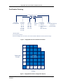
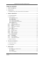
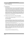
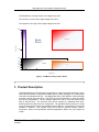
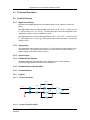
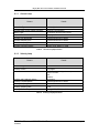
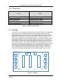
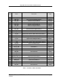
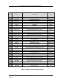
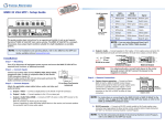
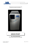
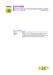
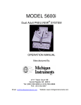
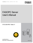
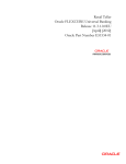
Mighty Mite Servo Drive Module
Installation Manual
Prepared By:
ESI Motion
2250A Union Place
Simi Valley, CA 93065
www.esimotion.com
Revision D Updated on 3/26/2015
ESI Motion Document 100249
Mighty Mite Servo Drive Module Installation Manual
Notice
This installation manual contains proprietary information belonging to ESI Motion.
The information provided is solely for the purpose of assisting users of the Mighty Mite Servo
Drive Module.
Information supplied in this manual is subject to change without notice.
ESI Motion Document 100249 Revision D
3/26/2015
Page 2
Mighty Mite Servo Drive Module Installation Manual
Revision Control
Revision
Date
Change Description
A
1/15/2015
Initial Release
B
1/16/2015
Corrected Table 7, added Section 6.1
C
1/27/2015
Updated Thermal Data (new potting compound)
D
3/26/2015
Updated Part Number Ordering and Voltage and Current Limits,
Added Configuration Options
ESI Motion Document 100249 Revision D
3/26/2015
Page 3
Mighty Mite Servo Drive Module Installation Manual
Part Number Ordering
M XXA YYYV P D -E -I
Servo Drive
M – Mighty Mite
Continuous
Current*
01 – 1A
02 – 2A
05 – 5A
10 – 10A
20 – 20A
40 – 40A
Voltage
012 – 12V
028 – 28V
048 – 48V
075 – 75V
170 – 170V
Case
P –Potted
Plastic
Configuration
Options
S – Single Axis
- E Extended Operating
D – Dual Axis
Temperature
P – Single Paralleled - I Include I/O PCBA
Axes**
(80A maximum)
* Peak Sine Wave
** 2 X Continuous Current
Current and Voltage values are nominal, refer to the Installation Manual for the full operational range.
Figure 1
Mighty Mite Servo Drive Module Part Number
40A
20A
10A
Continuous
Current
Available
Configurations
5A
2A
1A
12V
28V
48V
75V
170V
Voltage
Figure 2
Mighty Mite Servo Drive Configuration Options
ESI Motion Document 100249 Revision D
3/26/2015
Page 4
Mighty Mite Servo Drive Module Installation Manual
TABLE OF CONTENTS
1
SAFETY INFORMATION ........................................................................................................ 8
2
INTRODUCTION...................................................................................................................... 8
2.1 ESI Motion Family of Servo Drives and Servo Drive Modules .......................................... 8
3
PRODUCT DESCRIPTION .................................................................................................... 10
3.1 Functional Description ..................................................................................................... 11
3.2 Product Features ............................................................................................................. 11
3.2.1 High Power Density .............................................................................................. 11
3.2.2 Supply Input .......................................................................................................... 11
3.2.3 Servo Control ........................................................................................................ 11
3.2.4 Feedback Ports Options ....................................................................................... 11
3.2.5 Feedback Sensor Specifications .......................................................................... 11
3.2.6 Communications ................................................................................................... 11
3.2.7 Outputs ................................................................................................................. 11
3.2.7.1
Resolver Excitation............................................................................................... 11
3.2.7.2
Analog Test Points (ATPs) ................................................................................... 11
3.2.7.3
Brakes .................................................................................................................. 12
3.2.7.4
Regen, Inrush, Discharge .................................................................................... 12
3.2.7.5
Digital IO ............................................................................................................... 12
3.2.8 Inputs .................................................................................................................... 12
3.2.8.1
Current Command ................................................................................................ 12
3.2.8.2
Resolver ............................................................................................................... 13
3.2.8.3
Encoder / BiSS-C ................................................................................................. 13
3.2.8.4
Hall ....................................................................................................................... 14
3.2.8.5
Motor Temperature............................................................................................... 14
3.2.8.6
Vbus_Pre_Inrush .................................................................................................. 14
3.2.9 Built-In Protection ................................................................................................. 14
3.2.9.1
Over Current ......................................................................................................... 14
3.2.9.2
Over Voltage ........................................................................................................ 15
3.2.9.3
Over Temperature ................................................................................................ 15
3.2.9.4
Other Built-In Protection ....................................................................................... 15
3.3 System Architecture ........................................................................................................ 16
4
TECHNICAL INFORMATION ................................................................................................ 17
4.1 Physical Specification...................................................................................................... 17
4.2 Technical Data ................................................................................................................ 17
5
INSTALLATION ..................................................................................................................... 17
5.1 Connections .................................................................................................................... 18
5.1.1 Main Power and Motor Power .............................................................................. 19
5.1.2 Feedback .............................................................................................................. 20
5.1.3 Service .................................................................................................................. 21
5.1.4 Communication ..................................................................................................... 21
ESI Motion Document 100249 Revision D
3/26/2015
Page 5
Mighty Mite Servo Drive Module Installation Manual
5.2 Mounting to a PCBA ........................................................................................................ 21
5.3 Heat Sinking .................................................................................................................... 24
5.4 Powering Up .................................................................................................................... 24
5.5 Initializing the System...................................................................................................... 24
5.6 Heat Dissipation .............................................................................................................. 24
5.6.1 Thermal Conductivity Data ................................................................................... 24
5.6.2 Heat Sink Interface Materials ............................................................................... 26
6
TECHNICAL SPECIFICATIONS ........................................................................................... 26
6.1 Control Specifications...................................................................................................... 26
6.1.1 Current Loop ......................................................................................................... 27
6.1.2 Velocity Loop ........................................................................................................ 27
6.1.3 Position Loop ........................................................................................................ 28
6.2 I/O PCBA ......................................................................................................................... 28
7
APPENDICES ........................................................................................................................ 32
7.1 TBD ................................................................................................................................. 32
TABLE OF FIGURES
Figure 1
Figure 2
Figure 3
Figure 4
Figure 5
Figure 6
Figure 7
Figure 8
Figure 9
Figure 10
Figure 11
Figure 12
Figure 13
Figure 14
Figure 15
Figure 16
Figure 17
Mighty Mite Servo Drive Module Part Number ............................................................... 4
Mighty Mite Servo Drive Configuration Options ............................................................. 4
ESI Motion Family of Servo Drive Modules .................................................................... 9
ESI Motion Family of Servo Drives .............................................................................. 10
System Architecture ..................................................................................................... 16
Single Axis Package Dimensions and Mounting Pattern (in) ....................................... 17
Dual Axis Package Dimensions and Mounting Pattern (in) ......................................... 17
Dual-Axis Connections ................................................................................................. 18
Mighty Mite Servo Drive Module Single-Axis Connections .......................................... 19
Feedback Options ...................................................................................................... 20
Dual-Axis PCBA Footprint w/ Mating Connectors ...................................................... 22
Dual-Axis PCBA Footprint w/o Mating Connectors .................................................... 22
Single-Axis PCBA Footprint w/ Mating Connectors ................................................... 23
Single-Axis PCBA Footprint w/o Mating Connectors ................................................. 23
Maximum Current Command vs Case Temperature (Per Axis) ................................ 25
Maximum Current Command vs Case Temperature (Paralleled Axes) ..................... 26
I/O PCBA .................................................................................................................... 28
TABLES
Table 1
Table 2
Table 3
Table 5
Table 6
Table 7
Voltage and Current Limits ............................................................................................ 19
Thermal Resistance ....................................................................................................... 24
Current Command vs Case Temperature Rise ............................................................. 25
Thermal Interface Compounds ...................................................................................... 26
Current Loop Specification ............................................................................................ 27
Velocity Loop Specification ........................................................................................... 27
ESI Motion Document 100249 Revision D
3/26/2015
Page 6
Mighty Mite Servo Drive Module Installation Manual
Table 8 Position Loop Specification ........................................................................................... 28
Table 9 I/O PCBA, J11 Motor A Feedback ................................................................................. 29
Table 10 IO PCBA, J12 Service and Communication ................................................................ 30
Table 11 I/O PCBA, J13 Motor B Feedback ............................................................................... 31
Referenced Documents
ESI Document 100236, Mighty Mite Datasheet
ESI Document 100266, Controller User’s Manual
ESI Document 100211, ESI Motion’s CAN Protocol
ESI Document 100121, ESI Motion’s RS422 Protocol
ESI Motion Document 100249 Revision D
3/26/2015
Page 7
Mighty Mite Servo Drive Module Installation Manual
1
SAFETY INFORMATION
2
INTRODUCTION
This document will provide the user with an overview of the ESI Motion Family of Servo
Drives and Servo Drive Modules. Then provide a detailed description of the Mighty Mite
Servo Drive Module, the product features and system architecture. This document will
provide the user with details on the installation of the Mighty Mite Servo Drive Module. The
installation will cover the connections to the servo drive, mounting the servo drive to a
printed circuit board assembly (PCBA), heat sinking, powering up the drive, and initializing
the system. The connections to the Mighty Mite Servo Drive Module will be explored in
more detail; main power and motor power, feedback, service and communication. Other
sections of this manual will cover the technical specifications and thermal properties of the
Mighty Mite Servo Drive Module. A separate ESI Document 100226, Controller User’s
Manual is available for a more detailed discussion of the capabilities of ESI Motion’s Servo
Drive Modules. Refer to the ESI Document 100236, Mighty Mite Datasheet for details on
signal connections and electrical characteristics.
2.1
ESI Motion Family of Servo Drives and Servo Drive Modules
The ESI Motion Family of Servo Drives and Servo Drive Modules operate over voltages
ranging from 10 to 800V and currents up to 300A.
Servo Drive Modules
3
The Flea is our smallest servo drive module, measuring XX in , and weighing XX oz. The
servo drive module is designed to be mounted on a PCBA, allowing it to be integrated with
other system level components and possibly other servo drive modules in a multi-axis
design. The Flea is designed with XX FETs, which allows the Flea to be clocked at PWM
frequency up to XX, making it ideal for applications involving very low inductive loads. The
Flea operates between 10 to 50V at currents up to 10A.
The Mite is probably our most versatile servo drive module. The Mite is available as a
3
single-axis module, measuring 2.00 in and weighing 2.2 oz. (62.4 g), and a dual-axis
3
module, measuring 3.42 in and weighing 3.7 oz. (105 g). The Mite provides up to 2kW of
power per axis, packaged in a potted plastic case, and an integrated heat sink. The Mite
supports several motor feedback options, which are selected via software configuration
parameters. The Mite is ideal for precision military, aviation, automotive, robotic, and
specialized industrial applications where size and weight are critical. The Mite is also
available in an extended operating temperature range. The Mite operates between 10 to
170V at currents up to 30A.
The Tick is our high current, low voltage servo drive module.
The Scorpion is our low current, high voltage servo drive module.
ESI Motion Document 100249 Revision D
3/26/2015
Page 8
Mighty Mite Servo Drive Module Installation Manual
300
Current (A)
Servo
Drive
Modules
150
Tick
80
60
Wolverine
40
30
Scorpion
Mite
10
0
Flea
10
50
200
400
600
800
Voltage (V)
Figure 3
ESI Motion Family of Servo Drive Modules
Servo Drives
The Wolverine is a plug and play, stand-alone, military-grade submersible package, servo
drive based on our servo drive modules. An example of a Wolverine configuration would
be a Mite servo drive module packaged with supporting hardware to form a stand-alone
drive. The Wolverine includes a High Voltage Interlock and Brake Drivers, however
provides for optional Integrated EMI Filter, and DC Bus Voltage Regeneration switch and
active Inrush limiter. The Wolverine is designed to meet several military standards: MILSTD-810, MIL-STD-1275, MIL-STD-704, and MIL-STD-461. The Wolverine supports
several motor feedback options, which are selected via software configuration parameters.
The ruggedized package comes in three cooling options, Chassis, Fan, or liquid. The
Wolverine is designed for defense, automotive, energy, and specialized industrial
applications where a smaller, lighter weight servo drive is needed.
The Wolverine
operates between 10 to 610V at currents up to 80A.
The Dragon is a plug and play, stand-alone, military-grade submersible package, servo
drive based on our rugged controller and power drivers. The Dragon includes a High
Voltage Interlock, Brake Drivers, Integrated EMI Filter, and DC Bus Voltage Regeneration
switch and active Inrush limiter. The Dragon is designed to meet several military
standards: MIL-STD-810, MIL-STD-1275, MIL-STD-704, and MIL-STD-461. The Dragon
comes in three motor feedback configurations, Dual Resolver, Dual Encoder, and Single
Resolver with BiSS-C. The ruggedized package comes in three cooling options, Chassis,
Fan, or liquid. This versatile servo drive is ideal for high performance military, aviation, and
specialized industrial applications operating outdoor, at high temperatures, in high
vibration, or other extreme environ-mental conditions. The Dragon operates between 24 to
610V at currents up to 80A.
ESI Motion Document 100249 Revision D
3/26/2015
Page 9
Mighty Mite Servo Drive Module Installation Manual
The Roadwind is our high current, low voltage servo drive.
The Vulcan is our low current, high voltage servo drive.
The Hyperion is our high current, high voltage servo drive.
300
Current (A)
Road
Wind
Servo
Drives
Hyperion
150
80
60
40
30
Dragon
Vulcan
10
0
10
50
200
400
600
800
Voltage (V)
Figure 4
ESI Motion Family of Servo Drives
3 Product Description
The Mighty Mite Servo Drive Module incorporates our rugged controller and power drivers,
offers several software configurable feedback options, and is packaged in a potted plastic
case with an integrated heat sink. The Mighty Mite Servo Drive Module comes packaged
as either a dual or single axis drive. The servo drive can be ordered in a variety of voltage
and current configurations. The bus voltage ranges from 10V to 170V and currents up to
40A, at 2kW per axis. The dual axis drive can be ordered as a paralleled axes drive,
delivering twice the rated current of a single axis. The paralleled axes functions as a single
motor controller with all control and feedback through Motor A, all the Motor B control and
feedback is disabled. This versatile servo line is ideal for precision military, aviation,
automotive, robotic, and specialized industrial applications where size and weight are
critical.
ESI Motion Document 100249 Revision D
3/26/2015
Page 10
Mighty Mite Servo Drive Module Installation Manual
3.1
Functional Description
3.2
Product Features
3.2.1
High Power Density
Each axis in the Mighty Mite Servo Drive Module delivers up to 2000 W of continuous
power.
The Mighty Mite Servo Drive Module Dual Axis is 2.00” x 3.00” x 0.57”, a volume of 3.42
3
in , and a weight of 3.7 oz. (105 g). The Dual Axis servo drive has independent axis
configuration, torque, velocity, and position control.
The Mighty Mite Servo Drive Module Single Axis is 2.00” x 1.75” x 0.57”, a volume of 2.00
3
in , and a weight of 2.2 oz. (62.4 g). The Single Axis servo drive has torque, velocity, and
position control.
3.2.2
Supply Input
Two isolated DC power sources are required, 12 -170V for the main power and 5V for the
controller power. The feedback power source, either the same 5V for the controller, or
another supply, must share a common ground.
3.2.3
Servo Control
3.2.4
Feedback Ports Options
The Mighty Mite Servo Drive Module has five different forms of motor feedback,
Sensorless, Digital Encoder, Resolver, Hall, and BiSS-C.
3.2.5
Feedback Sensor Specifications
3.2.6
Communications
3.2.7
Outputs
3.2.7.1
Resolver Excitation
20.0K
Sine IN
0.1
4.99K
EXE+
G=4
EXE0.1
4.99K
20.0K
3.2.7.2
Analog Test Points (ATPs)
ESI Motion Document 100249 Revision D
3/26/2015
Page 11
Mighty Mite Servo Drive Module Installation Manual
10.0 K
+5V
5
4.99 K
3
1.5V_REF
1
ATPx
4.99 K
49.9
-
4
BUF_ATPx
+
10.0 K 2
-5V
3.2.7.3
Brakes
49.9
BRAKE_Mx
DBRAKE_Mx
3.2.7.4
Regen, Inrush, Discharge
49.9
DREGEN
REGEN
49.9
DINRUSH
INRUSH
49.9
DDISCHARGE
3.2.7.5
DISCHARGE
Digital IO
49.9
DIG_IO
DDIG_IO
3.2.8
Inputs
3.2.8.1
Current Command
1000p
10.0 K
3.3V
A2
+
1.50K
CMD-_Mx
-
CMD+_Mx
+
BUF_CMD_Mx
10.0 K
1.50K
0.1
D1
1000p
1.5V REF
ESI Motion Document 100249 Revision D
3/26/2015
Page 12
Mighty Mite Servo Drive Module Installation Manual
3.2.8.2
Resolver
470p
4.99 K
10.0 K
-
SIN+_COS+_Mx
BUF_SIN+_COS+_Mx
+
3.3V
10.0 K
A2
+
1.5V REF
470p
0.1
D1
4.99 K
10.0 K
-
SIN-_COS-_Mx
BUF_SIN-_COS-_Mx
+
10.0 K
1.5V REF
3.2.8.3
Encoder / BiSS-C
+5V
VCC 16
0.1
4 1DE
BISS_TXA_EN
BISS_CLK_MA
15 1D
GND 8
PAD 17
1Y 14
1Z 13
A+_MA
A-_MA
1.0 K
3 1R
A_MA
2.00 K
1A 2
1B 1
120
12 2DE
BISS_TXB_EN
BISS_CLK_MB
9 2D
2Y 10
2Z 11
5 2R
4Y 6
4Z 7
A+_MB
A-_MB
1.0 K
A_MA
120
2.00 K
3.3V
VCC 16
3.3V
0.1
4 G
12 *G
B+_MA
120
2 A1
1 B1
Y1 3
120
6 A2
7 B2
Y2 5
120
10 A3
9 B3
Y 3 11
120
14 A4
15 B4
Y 4 13
B-_MA
I+_MA
I-_MA
B+_MB
B-_MB
I+_MB
I-_MB
ESI Motion Document 100249 Revision D
3/26/2015
GND 8
PAD 17
B_MA
I_MA
BISS_MA
B_MB
I_MB
BISS_MB
Page 13
Mighty Mite Servo Drive Module Installation Manual
3.2.8.4
Hall
+5V
3.3V
3.3V
1.0 K
10.0 K
10.0 K
5
HALL_X_Mx
6
-
A2
+
14
HALL_X_BUF_Mx
+
0.1
D1
20.0 K
10.0 K
1.5V_REF
3.2.8.5
Motor Temperature
3.3V
10.0 K
1.0 K
3V_REF
MOTOR_TEMP+_Mx
10.0 K
A2
+
BUF_MOTOR_TEMP_Mx
+
MOTOR_TEMP-_Mx
0.1
D1
10.0 K
1.0 K
3.2.8.6
0.1
Vbus_Pre_Inrush
3.3V
2.00 K
10.0 K
A2
+
-
VBUS_PRE_INRUSH
+
10.0 K
BUF_VBUS_PRE_INRUSH
0.1
D1
1.5V_REF
3.2.9
Built-In Protection
3.2.9.1 Over Current
The Mighty Mite Servo Drive Module’s motor phase current is always monitored and when
the current on any phase exceeds the over current limit, usually defined to be 1.25 * peak
current, the servo drive module will disable its self. The servo drive module can only be reenabled when the fault is removed and the fault state cleared. Please refer to the ESI
Motion Controller User’s Manual for details.
ESI Motion Document 100249 Revision D
3/26/2015
Page 14
Mighty Mite Servo Drive Module Installation Manual
3.2.9.2 Over Voltage
The Mighty Mite Servo Drive Module’s bus voltage is always monitored and when the bus
voltage exceeds the over-voltage limit for motor or the servo drive module, whichever is
lower, the servo drive module will disable its self. The servo drive module can only be reenabled when the fault is removed and the fault state cleared. Please refer to the ESI
Motion Controller User’s Manual for details.
3.2.9.3 Over Temperature
The Mighty Mite Servo Drive Module has sensors that monitor the processor temperature
as well as both motor A and B power driver sections. Software will alert the user with a
warning flag, if the temperature nears the critical level, and is programmed to shut itself off
or shut down the power driver section if the temperature reaches the critical level. The
servo drive module can only be re-enabled when the fault is removed and the fault state
cleared. Please refer to the ESI Motion Controller User’s Manual for details.
3.2.9.4 Other Built-In Protection
The Mighty Mite Servo Drive Module has other protection a BIT (Built In Test), Motor Over
Temperature with a user provided thermistor, Motor Over Speed, Bus Under Voltage,
Motor Loss of Feedback, and an I-squared-T (I2T), which is an estimate of the energy
content in current transient conditions, this can help protect against motor overheating.
The servo drive module can only be re-enabled when the fault is removed and the fault
state cleared. Please refer to the ESI Motion Controller User’s Manual for details.
ESI Motion Document 100249 Revision D
3/26/2015
Page 15
Mighty Mite Servo Drive Module Installation Manual
3.3
System Architecture
VDC_IN
VDC_RTN
CHASSIS
A
Motor
B
C
CMD+_MB
CMD-_MB
SIN+_MB
SIN-_MB
COS+_MB
COS-_MB
EXE+_MB
EXE-_MB
Power
Power
Spade Pins
Spade Pins
Motor B
Mounting Hole
Mounting Hole
Spade Pins
Spade Pins
Feedback**
Feedback
Current
Command
Current
Command
Motor A
VDC_IN
VDC_RTN
CHASSIS
A
Motor
A
CMD+_MA
CMD-_MA
SIN+_MA
SIN-_MA
COS+_MA
COS-_MA
EXE+_MA
EXE-_MA
Resolver
Feedback
Resolver
Feedback
Encoder/
BiSS-C
Feedback
Encoder/
BiSS-C
Feedback
HALL_A_MB
HALL_B_MB
HALL_C_MB
Hall
Feedback
Hall
Feedback
HALL_A_MA
HALL_B_MA
HALL_C_MA
MOTOR_TEMP+_MB
MOTOR_TEMP-_MB
Motor
Temperature
Motor
Temperature
MOTOR_TEMP+_MA
MOTOR_TEMP-_MA
Brake
Command
Brake
Command
BRAKE_MA*
Service
Communication
+5V_IN
+5V_RTN
Controller
Voltage IN
RS422
Transmit
RS422_TX_P
RS422_TX_N
BUF_ATP1
BUF_ATP2
ANALOG_REF
Analog Test
Points and
Reference
RS422
Receive
RS422_RX_P
RS422_RX_N
CAN
CAN_H
CAN_L
REGEN*
INRUSH*
DISCHARGE*
DC Bus Voltage
Regeneration,
Inrush, and
Discharge
USB
USB_DP
USB_DN
High Speed
Serial Bus
Transmit
HSSB_TX_CLK
HSSB_TX_SYNC
HSSB_TX_DATA
High Speed
Serial Bus
Receive
HSSB_RX_CLK
HSSB_RX_SYNC
HSSB_RX_DATA
A+/BISS_CLK+_MB
A-/BISS_CLK-_MB
B+_MB
B-_MB
I+/BISS_DATA+_MB
I-/BISS_DATA-_MB
BRAKE_MB*
VBUS_PRE_INRUSH
DIG_IO
DIGITAL_REF
DC Bus Voltage
Monitor Prior to
Inrush
Digital I/O and
Reference
Serial
Communication
Interface
A+/BISS_CLK+_MA
A-/BISS_CLK-_MA
B+_MA
B-_MA
I+/BISS_DATA+_MA
I-/BISS_DATA-_MA
SCI_TX
SCI_RX
* Logic level only, external circuit required.
** Available on Dual-Axis only.
Figure 5
ESI Motion Document 100249 Revision D
3/26/2015
System Architecture
Page 16
Mighty Mite Servo Drive Module Installation Manual
4
4.1
TECHNICAL INFORMATION
Physical Specification
Figure 6
Figure 7
4.2
5
Single Axis Package Dimensions and Mounting Pattern (in)
Dual Axis Package Dimensions and Mounting Pattern (in)
Technical Data
INSTALLATION
The Mighty Mite Servo Drive Module is designed to mount to a PCBA. The Mighty Mite
Servo Drive Module can be purchased with an ESI furnished I/O PCBA, designed to be used
for system development, please refer to Figure 1
Mighty Mite Servo Drive Module Part
Number, - I option. The mechanical and electrical interfaces for the ESI furnished I/O PCBA
can be found in the Mighty Mite Servo Drive Module’s Datasheet. This section will provide
the user with the information required to design and develop a PCBA to interface to the
Mighty Mite Servo Drive Module.
ESI Motion Document 100249 Revision D
3/26/2015
Page 17
Mighty Mite Servo Drive Module Installation Manual
5.1
Connections
The connections to the Mighty Mite Servo Drive Module can be divided up into four groups,
Main Power and Motor Power, Feedback, Service, and Communication. Please refer to
Figure 5
System Architecture for details. These connections are available in both the
Dual and Single-Axis drive; however the Single-Axis drive does not have any connections
on Motor B Feedback.
Motor A
Motor B
VDC_IN
VDC_IN
2
A
A
The Mighty Mite Servo Drive Module Dual-Axis is shown below.
40
J1
39
2
40
B
B
1
J2
39
C
C
1
VDC_RTN
VDC_RTN
Chassis x4
Heat Sink
Figure 8
ESI Motion Document 100249 Revision D
3/26/2015
Dual-Axis Connections
Page 18
Mighty Mite Servo Drive Module Installation Manual
The Mighty Mite Servo Drive Module Single-Axis is shown below.
Motor A
A
VDC_IN
2
40
J1
39
B
1
2
40
J2
39
C
1
VDC_RTN
Chassis x4
Figure 9
5.1.1
Heat Sink
Mighty Mite Servo Drive Module Single-Axis Connections
Main Power and Motor Power
The Main Power and Motor Power are the high current connections to the Mighty Mite
Servo Drive Module. The Main Power connections are located on the top (VDC_IN) and
bottom (VDC_RTN) of the servo drive module. The Dual-Axis servo drive provides two
VDC_IN and two VDC_RTN pins. Motor A and B have their own dedicated Main Power
pins; refer to Figure 8
Dual-Axis Connections. The two VDC_IN pins and two
VDC_RTN pins are electrically equivalent; however the current carrying capability is
through the motor dedicated pins and should not be interchanged. The Motor Power,
phase A, B, and C are located on the sides of the servo drive module. Table I shows
nominal voltage and continuous current used for ordering the Mighty Mite Servo Drive
Module, based on Figure 1 Mighty Mite Servo Drive Module Part Number, and the peak
voltage and current, which should not be exceeded.
Voltage (V)
Continuous Current (A)
Nominal
Maximum
Nominal
Maximum
12
20
1
2
28
35
2
4
48
70
5
10
75
100
10
20
170
200
20
40
40
60
Table 1
Voltage and Current Limits
ESI Motion Document 100249 Revision D
3/26/2015
Page 19
Mighty Mite Servo Drive Module Installation Manual
5.1.2
Feedback
The Mighty Mite Servo Drive Module Feedback connections are divided into motor A and
motor B feedback. The Feedback has motor Current Command, Feedback options,
Temperature, and Brake. The Current Command is an analog input, mapped and scaled
through software configuration, to the motor current control loop. The Temperature input
is an active circuit that measures an NTC thermistor which is directly proportional to
motor temperature. The temperature vs resistance polynomial can be configured through
software.
The Brake output is a TTL discrete that can be used to engage or disengage an external
brake circuit. The user will be required to implement the external brake circuit using i.e. a
MOSFET switch. When the logic level is high the brake is assumed to be engaged or
that the MOSFET switch is open and no current is flowing through the brake coil.
The Mighty Mite Servo Drive Module has five different forms of motor feedback,
Sensorless, Digital Encoder, Resolver, Hall, and BiSS-C. Feedback options are selected
through software configuration settings, each motor feedback can be configured
exclusive of the other. The majority of the feedback options have their own independent
hardware interface, only the Encoder and BiSS-C share common hardware connections.
Sensorless is the only feedback that does not require any external connections. Figure
10
Feedback Options shows the connections required for each feedback
implementation.
Feedback
Feedback
A+
A-
EXE+
EXE-
B+
B-
COS+
COS-
I+
I-
Resolver
SIN+
SIN-
Digital
Encoder
Service
+5V_IN
+5V_RTN
Controller
Voltage IN
Power
Supply
Feedback
Feedback
HALL_A
HALL_B
HALL_C
BiSS_CLK+
BiSS_CLK-
HALL
Sensors
Service
Controller
Voltage IN
BiSS_DATA+
BiSS_DATA-
+5V_IN
+5V_RTN
BiSS-C
Encoder
Service
Controller
Voltage IN
+5V_IN
+5V_RTN
Power
Supply
Power
Supply
Twisted Pair
Figure 10
ESI Motion Document 100249 Revision D
3/26/2015
Feedback Options
Page 20
Mighty Mite Servo Drive Module Installation Manual
5.1.3
Service
The Mighty Mite Servo Drive Module Service signals are:
Controller Voltage In
Analog Test Points, Buf_ATP#
Regeneration, Inrush, and Discharge
Vbus_Pre_Inrush
Digital I/O
(+5V In)
(Analog Outputs)
(Digital Outputs)
(Analog Input)
(Digital In/Output)
The Controller Voltage In is the +5V input to power the servo drive controller. The power
to any external motor feedback sensors should be referenced to the +5V supply. There
are two Analog Test Point outputs, Buf_ATP1 and Buf_ATP2, which are configured
through software. These signals can be mapped to various control parameters. The
Analog_Ref signal should be used as the reference for the analog test points. The
Regeneration discrete can be used, with an external circuit, to switch the bus voltage
(VDC_IN) to a load resistor, when the bus voltage exceeds a software configurable limit.
The duty cycle and duration of the Regeneration discrete is also configurable through
software. The Inrush discrete can be used to control an external switch that will slow the
RC rise time of the bus voltage as it charges the capacitor bank during power up. When
the bus voltage reaches a software configurable limit the Inrush discrete will switch off.
The Discharge discrete can be used, with an external circuit, to discharge the bus voltage
capacitor bank, during power down, safely removing power from the system in a timely
fashion. The Vbus_Pre_Inrush is an analog input that can be used to monitor the bus
voltage prior to the Inrush switch. The Digital I/O is a software configurable input or
output pin and can be mapped to various system events. Refer to the section on
Software for further details.
5.1.4
Communication
The Mighty Mite Servo Drive Module has several forms of communication. The RS422,
CAN, and USB are standard on the servo drive and have a defined software protocol.
The High Speed Serial Bus (HSSB) and Serial Communication Interface (SCI) are to be
used for customer specific applications and are not accessible with the standard servo
drive software package. This document will only discuss the RS422, CAN and USB
interfaces. All three interfaces provide the user with complete flexibility in controller
configuration, commands, and feedback. The CAN and USB interfaces work directly with
the Host Interface for the Dragon Servo (HiDS), user friendly GUI with enhanced data
collection capability. The uses and capability and of HiDS can be found in ESI Document
100266, Controller User’s Manual. ESI Document 100211, ESI Motion’s CAN Protocol
and ESI Document 100121, ESI Motion’s RS422 Protocol are also available.
5.2
Mounting to a PCBA
The Mighty Mite Servo Drive Module has two pin headers J1 and J2, Samtec part number
FTS-120-01-L-DV, 2 x 20 pins and 0.05” pitch. The main power and motor power are
“spade” shaped copper pins that are soldered to the PCBA. The dimension and location of
the mounting holes for the “spade” shaped pins is shown in Figure 11 through Figure 14,
Mighty Mite Dual and Single-Axis PCBA Footprints. The headers J1 and J2 can be
soldered directly to the PCBA or mated with Samtec part number CLP-120-02-F-D-TR.
The mating height for J1 and J2 to Samtec part number CLP-120-02-F-D-TR is 0.14”. The
length of the “spade” pins will accommodate either configuration. If PCBA area is at a
premium, the use of mating connectors for J1 and J2 will allow the user to place low profile
components underneath the Mighty Mite Servo Drive Module.
ESI Motion Document 100249 Revision D
3/26/2015
Page 21
Mighty Mite Servo Drive Module Installation Manual
Figure 11
Figure 12
Dual-Axis PCBA Footprint w/ Mating Connectors
Dual-Axis PCBA Footprint w/o Mating Connectors
ESI Motion Document 100249 Revision D
3/26/2015
Page 22
Mighty Mite Servo Drive Module Installation Manual
Figure 13
Figure 14
Single-Axis PCBA Footprint w/ Mating Connectors
Single-Axis PCBA Footprint w/o Mating Connectors
ESI Motion Document 100249 Revision D
3/26/2015
Page 23
Mighty Mite Servo Drive Module Installation Manual
5.3
Heat Sinking
The Mighty Mite Servo Drive Module comes with an integrated heat sink on the side
opposite to PCBA mounting. The integrated heat sink is designed to be used alone,
without any external heat sink mass, for motor currents, up to 5A per axis. For applications
requiring higher currents a proper heat sink design must be used with the Mighty Mite
Servo Drive Module, please refer to the section on Heat Dissipation for details.
5.4
Powering Up
The Mighty Mite Servo Drive Module has two voltage sources, bus and controller voltage.
The bus voltage should be set to a voltage below the configuration peak voltage, see Table
1
Voltage and Current Limits, Mighty Mite Servo Drive Module Voltage and Current
Limits. If the peak voltage is exceeded, software will trigger a bus over voltage fault, and
disable the servo drive. The controller voltage should be set to +5V +/- 10%. The bus and
controller voltages can be applied to the servo drive in either order. When the controller
voltage is applied to the servo drive the configuration of the module is read and voltage
and current limits are set to their default values.
5.5
Initializing the System
The Mighty Mite Servo Drive Module will remain disabled, until it receives a command to
enable and no system faults are active. If the servo drive module is disabled, due to a
system fault, the system fault or faults must be resolved and a reset command sent to
servo drive module prior to another enable command. ESI Motion Controller User’s
Manual will provide the user with the information necessary to successfully configure and
run the Mighty Mite Servo Drive Module.
5.6
5.6.1
Heat Dissipation
Thermal Conductivity Data
The Mighty Mite Servo Drive Module thermal resistance was measured from component
junction to the heat sink base plate. Refer to Table 2 Thermal Resistance.
Symbol
Tjb
Description
Theta Junction to Base Plate
Table 2
ºC/W
9.52
Thermal Resistance
The following is thermal data collected from the Mighty Mite Servo Drive Module mounted
on a 5” x 6” x 0.5” aluminum heat sink with phase change thermal interface compound,
Aavid Thermalloy, part number 100300F00000G.
ESI Motion Document 100249 Revision D
3/26/2015
Page 24
Mighty Mite Servo Drive Module Installation Manual
Table 3
Current
Command (A)
Case
Temperature Rise
(ºC)
10
20
30
40
50
60
70
3.5
6.0
9.8
14.3
20.9
27.5
36.4
Current Command vs Case Temperature Rise
Maximum Current Command (Per Axis)
45
40
35
30
25
Current (A) vs Temp °C
20
15
10
5
0
0
20
Figure 15
40
60
100
120
Maximum Current Command vs Case Temperature (Per Axis)
ESI Motion Document 100249 Revision D
3/26/2015
80
Page 25
Mighty Mite Servo Drive Module Installation Manual
Maximum Current Command (Paralleled Axes)
90
80
70
60
50
Current (A) vs Temp °C
40
30
20
10
0
0
20
40
Figure 16
5.6.2
60
80
100
120
Maximum Current Command vs Case Temperature (Paralleled Axes)
Heat Sink Interface Materials
If a heat sink is needed, effective coupling of the Mighty Mite base plate to the heat sink is
essential for optimum heat transfer. Depending on the operating current and the amount of
heat dissipated, various methods are available to achieve a good thermal bond. Table 4
Thermal Interface Compounds shows examples of thermal interface compounds which can
be used with the Mighty Mite Servo Drive Module.
Thermal
Interface
Compound
Supplier
Part Number
Thermal
Conductivity
Operating
Temperature
Phase Change
Aavid Thermalloy
100300F00000G
0.79 W/(m-°C)
-40°C to 200°C
Gap Pad
Bergquist
GP1500
1.5 W/(m-°C)
-60°C to 200°C
Thermal Grease
Aavid Thermalloy
100100F00000G
0.73 W/(m-°C)
-40°C to 200°C
Table 4
6
Thermal Interface Compounds
TECHNICAL SPECIFICATIONS
[Insert objective here.]
6.1
Control Specifications
ESI Motion Document 100249 Revision D
3/26/2015
Page 26
Mighty Mite Servo Drive Module Installation Manual
6.1.1
Current Loop
Feature
Details
Controller Type
Vector, digital
Compensation for bus voltage variations
Automatic compensation
Motor Types
DC Brushless, Brushed, and Induction
Current Control
Fully digital, Sinusoidal with vector control
Current Loop Bandwidth
Contact ESI Motion for details
Current Sampling Time
Contact ESI Motion for details
Current Sampling Rate
10 Khz, 20 Khz
Current Command options
Analog, HiDS, RS422, or CAN
Table 5
6.1.2
Current Loop Specification
Velocity Loop
Feature
Details
Controller Type
PID
Velocity Control
Velocity and Feedback options
Fully digital
Encoder Incremental (quadrature)
BISS-C Encoder
Hall
Resolver
Sensorless
Velocity Loop Bandwidth
Contact ESI Motion for details
Velocity Sampling Time
Contact ESI Motion for details
Velocity Sampling Rate
5 Khz
Velocity Command options
Analog, HiDS, RS422, or CAN
Table 6
Velocity Loop Specification
ESI Motion Document 100249 Revision D
3/26/2015
Page 27
Mighty Mite Servo Drive Module Installation Manual
6.1.3
Position Loop
Feature
Details
Controller Type
PID
Position Loop Bandwidth
Contact ESI Motion for details
Position Sampling Time
Contact ESI Motion for details
Position Sampling Rate
1 Khz
Position Command options
Analog, HiDS, RS422, or CAN
Table 7
6.2
Position Loop Specification
I/O PCBA
The I/O PCBA is an optional circuit board that can be purchased along with the Mighty Mite
Servo Module. The I/O PCBA provides the user with a platform that can be used for
system development, prior to the design of a user defined PCBA that will mate with the
Mighty Mite Servo Drive Module. The I/O PCBA provides all the connections necessary for
motor control, the signals are arranged into three groups, J11 Motor A Feedback, J12
Service and Communication, and J13 Motor B Feedback. Refer to ESI Document 100236,
Mighty Mite Datasheet for the electrical characteristics of each signal. A 5V regulator on
the I/O PCBA is used to power both the Mighty Mite Servo Module controller and external
motor feedback devices. The I/O PCBA is designed to work with Main Power (VDC_IN)
from 10V to 95V and provides a regulated 5V at 2.5A. The I/O PCBA that will be used with
Main Power (VDC_IN) that exceeds 95V will require the 5V regulator to be disabled. An
I/O PCBA that is purchased with a Mighty Mite Servo Module that uses a Main Power
(VDC_IN) that exceeds 95V will already have the 5V regulator disabled. Refer to ESI
Document 100236, Mighty Mite Datasheet for the mechanical details of the I/O PCBA.
Mite IO Board
VDC
Mite Module
J11
USB
J10
JTAG J9
J12
GND
MA_A
MB_A
MA_B
MB_B
MA_C
MB_C
Figure 17
ESI Motion Document 100249 Revision D
3/26/2015
J13
I/O PCBA
Page 28
Mighty Mite Servo Drive Module Installation Manual
PIN
Name
Description
Type
1
2
CMD+_MA
Current Command Positive Motor A
Analog In
CMD-_MA
Current Command Negative Motor A
Analog In
3
SIN+_MA
Resolver Sin Positive Motor A
Analog In
4
SIN-_MA
Resolver Sin Negative Motor A
Analog In
5
COS+_MA
Resolver Cos Positive Motor A
Analog In
6
COS-_MA
Resolver Cos Negative Motor A
Analog In
7
EXE+_MA
Resolver Excitation Positive Motor A
Analog Out
8
EXE-_MA
Resolver Excitation Negative Motor A
Analog Out
9
+5V_OUT
Power to Feedback Devices
Digital Power
10
+5V_RTN
Power Return
Digital Power
11
A+_MA
Digital Encoder A Positive / BiSS-C Clock Positive Motor A
Digital In / Out
12
A-_MA
Digital Encoder A Negative / BiSS-C Clock Negative Motor A
Digital In / Out
13
B+_MA
Digital Encoder B Positive Motor A
Digital In
14
B-_MA
Digital Encoder B Negative Motor A
Digital In
15
I+_MA
Digital Encoder I Positive / BiSS-C Data Positive Motor A
Digital In/Out
16
I-_MA
Digital Encoder I Negative / BiSS-C Data Negative Motor A
Digital In / Out
17
+5V_OUT
Power to Feedback Devices
Digital Power
18
+5V_RTN
Power Return
Digital Power
19
HALL_A_MA
Hall A Motor A
Digital In
20
HALL_B_MA
Hall B Motor A
Digital In
21
HALL_C_MA
Hall C Motor A
Digital In
22
PWR_REF
Power Reference
Analog
23
PWR_REF
Power Reference
Analog
24
PWR_REF
Power Reference
Analog
25
MOTOR_TEMP+_MA
Temperature Positive Motor A
Analog
26
MOTOR_TEMP-_MA
Temperature Negative Motor A
Analog
27
BRAKE_MA
Brake Command Motor A
Digital Out
28
DIG_REF
Digital Reference
Digital
29
PWR_REF
Power Reference
Analog
30
PWR_REF
Power Reference
Analog
Table 8
I/O PCBA, J11 Motor A Feedback
ESI Motion Document 100249 Revision D
3/26/2015
Page 29
Mighty Mite Servo Drive Module Installation Manual
PIN
Name
Description
Type
1
RS422_TX_P
RS422 Transmit Positive
Digital Out
2
RS422_TX_N
RS422 Transmit Negative
Digital Out
3
RS422_RX_P
RS422 Receive Positive
Digital In
4
RS422_RX_N
RS422 Receive Negative
Digital In
5
CAN_H
CAN High
Digital
6
CAN_L
CAN Low
Digital
7
HSSB_TX_CLK
High Speed Serial Bus Transmit Clock
Digital Out
8
HSSB_RX_CLK
High Speed Serial Bus Receive Clock
Digital In
9
HSSB_TX_SYNC
High Speed Serial Bus Transmit Sync
Digital Out
10
HSSB_RX_SYNC
High Speed Serial Bus Receive Sync
Digital In
11
HSSB_TX_DATA
High Speed Serial Bus Transmit Data
Digital Out
12
HSSB_RX_DATA
High Speed Serial Bus Receive Data
Digital In
13
PWR_REF
Power Reference
Analog
14
PWR_REF
Power Reference
Analog
15
DIG_REF
Digital Reference
Digital
16
DIG_IO
Digital Input / Output
Digital In / Out
17
+5V_OUT
Power to Feedback Devices
Digital Power
18
+5V_RTN
Power Return
Digital Power
19
SCI_TX
Serial Communication Interface (SCI) Transmit
Digital Out
20
SCI_RX
Serial Communication Interface (SCI) Receive
Digital In
21
BUF_ATP1
Analog Test point 1
Analog Out
22
BUF_ATP2
Analog Test point 2
Analog Out
23
ANALOG_REF
Analog Reference
Analog
24
PWR_REF
Power Reference
Analog
25
REGEN
DC Bus Voltage Regeneration Command
Digital Out
26
INRUSH
DC Bus Voltage Inrush (Precharge) Command
Digital Out
27
DISCHARGE
DC Bus Voltage Discharge Command
Digital Out
28
VBUS_PRE_INRUSH
DC Bus Voltage Monitor Prior to Inrush
Analog In
29
PWR_REF
Power Reference
Analog
30
PWR_REF
Power Reference
Analog
Table 9
IO PCBA, J12 Service and Communication
ESI Motion Document 100249 Revision D
3/26/2015
Page 30
Mighty Mite Servo Drive Module Installation Manual
PIN
Name
Description
Type
1
2
CMD+_MB
Current Command Positive Motor B
Analog In
CMD-_MB
Current Command Negative Motor B
Analog In
3
SIN+_MB
Resolver Sin Positive Motor B
Analog In
4
SIN-_MB
Resolver Sin Negative Motor B
Analog In
5
COS+_MB
Resolver Cos Positive Motor B
Analog In
6
COS-_MB
Resolver Cos Negative Motor B
Analog In
7
EXE+_MB
Resolver Excitation Positive Motor B
Analog Out
8
EXE-_MB
Resolver Excitation Negative Motor B
Analog Out
9
+5V_OUT
Power to Feedback Devices
Digital Power
10
+5V_RTN
Power Return
Digital Power
11
A+_MB
Digital Encoder A Positive / BiSS-C Clock Positive Motor B
Digital In / Out
12
A-_MB
Digital Encoder A Negative / BiSS-C Clock Negative Motor B
Digital In / Out
13
B+_MB
Digital Encoder B Positive Motor B
Digital In
14
B-_MB
Digital Encoder B Negative Motor B
Digital In
15
I+_MB
Digital Encoder I Positive / BiSS-C Data Positive Motor B
Digital In / Out
16
I-_MB
Digital Encoder I Negative / BiSS-C Data Negative Motor B
Digital In / Out
17
+5V_OUT
Power to Feedback Devices
Digital Power
18
+5V_RTN
Power Return
Digital Power
19
HALL_A_MB
Hall A Motor B
Digital In
20
HALL_B_MB
Hall B Motor B
Digital In
21
HALL_C_MB
Hall C Motor B
Digital In
22
PWR_REF
Power Reference
Analog
23
PWR_REF
Power Reference
Analog
24
PWR_REF
Power Reference
Analog
25
MOTOR_TEMP+_MB
Temperature Positive Motor B
Analog
26
MOTOR_TEMP-_MB
Temperature Negative Motor B
Analog
27
BRAKE_MB
Brake Command Motor B
Digital Out
28
DIG_REF
Digital Reference
Digital
29
PWR_REF
Power Reference
Analog
30
PWR_REF
Power Reference
Analog
Table 10
I/O PCBA, J13 Motor B Feedback
ESI Motion Document 100249 Revision D
3/26/2015
Page 31
Mighty Mite Servo Drive Module Installation Manual
7
7.1
APPENDICES
TBD
ESI Motion Document 100249 Revision D
3/26/2015
Page 32