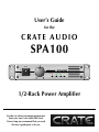
1
User’s Guide
for the
C R AT E A U D I O
SPA100
Power
On
Off
Power
Signal
Limit
Protect
1/2-Rack Power Amplifier
In order to achieve maximum performance
from your new Crate Audio SPA Series
Power Amp we recommend that you read
this user’s guide prior to its use.
SPA100
1/2-Rack Power Amplifier
Table of Contents:
Introduction . . . . . . . . . . . . . . . . . . . . . . . . . . . . . . . . . . . . .3
Features . . . . . . . . . . . . . . . . . . . . . . . . . . . . . . . . . . . . . . . .3
Front Panel Information . . . . . . . . . . . . . . . . . . . . . . . . . . . . .4
Rear Panel Information . . . . . . . . . . . . . . . . . . . . . . . . . . . . .5
Speaker Impedances And Power Ratings . . . . . . . . . . . . . . . .6
Joining Two Amplifers For Rack Mounting . . . . . . . . . . . . . . .6
Installations and Operation
Mono Operation (One Amplifier) . . . . . . . . . . . . . . . . . .7
Stereo Operation (Two Amplifiers) . . . . . . . . . . . . . . . . .8
Main / Monitor Combination (Two Amplifiers) . . . . . . . . .9
Biamping (Two Amplifiers) . . . . . . . . . . . . . . . . . . . . . .10
Triamping (Three Amplifiers) . . . . . . . . . . . . . . . . . . . . .11
System Block Diagram . . . . . . . . . . . . . . . . . . . . . .back cover
Technical Specifications . . . . . . . . . . . . . . . . . . . . .back cover
1.
2.
3.
4.
5.
6.
7.
Read these instructions.
Keep these instructions.
Heed all warnings.
Follow all instructions.
Do not use this apparatus near water.
Clean only with a damp cloth.
Do not block any of the ventilation openings. Install in accordance with the manufacturer’s
instructions.
8. Do not install near any heat sources such as radiators, heat registers, stoves, or other
apparatus (including amplifiers) that produce heat.
9. Do not defeat the safety purpose of the polarized-type plug. A polarized plug has two
blades with one wider than the other. The wide blade is provided for your safety. When
the provided plug does not fit into your outlet, consult an electrician for replacement of the
obsolete outlet.
10.Protect the power cord from being walked on or pinched particularly at plug, convenience
receptacles, and the point where they exit from the apparatus.
11. Only use attachments/accessories specified by the manufacturer.
12.Use only with a cart, stand, tripod, bracket, or table specified by the
manufacturer, or sold with the apparatus. When a cart is used, use
caution when moving the cart/apparatus combination to avoid injury
from tip-over.
13.Unplug this apparatus during lightning storms or when unused for long periods of time.
14.Refer all servicing to qualified service personnel. Servicing is required when the apparatus
has been damaged in any way, such as power-supply cord or plug is damaged, liquid has
been spilled or objects have fallen into the apparatus, the apparatus has been exposed to
rain or moisture, does not operate normally, or has been dropped.
2
SPA100
1/2-Rack Power Amplifier
Introduction:
Congratulations. You have selected one of the finest sound reinforcement amplifiers available,
the Crate Audio SPA100 1/2-Rack Power Amplifier. Our many years of experience in high-performance audio equipment, combined with our extensive research and development procedures, have
enabled us to produce an amplifier which provides the highest quality and reliability possible.
Like all Crate products, your SPA100 amplifier was designed and manufactured using only the
finest components and materials. Each amplifier design must satisfy our team of highly-trained technicians and musicians before it is approved. We insist upon high level of quality control to ensure that
each amplifier produced will provide its owner with years of trouble-free, ear-pleasing performance.
Your new SPA100 is a flexible part of any sound system – simple to connect and easy to operate
– if you first know how to incorporate it into your application. Several configurations are covered in
this manual, along with important information regarding impedance ratings and output power. In
order to get the best performance and highest level of quality and reliability from your new amplifier,
please read this user’s guide before operating the unit.
Features:
The Crate SPA100 is a ruggedly constructed high quality power amplifier designed to give you
continuous performance with professional results. Two of these amplifiers can be mounted side by side
in a standard 19” rack, requiring only 1-3/4 inches of vertical rack space. The automatic variablespeed internal cooling system uses the front, side and rear of the amplifier - not the top and bottom for its air intake and exhaust, allowing you to stack multiple components closer together in a rack
mount situation.
The SPA100 produces up to 100 watts of power @ 4 ohms, or 75 watts @ 8 ohms. Several “professional” features have been built into the SPA100, such as 1/4” phone and XLR input jacks with electronically balanced Low or High impedance operation. Built-in limiting circuitry constantly monitors
the output of the amplifier for clipping, thus helping prevent the generation of speaker-damaging
square waves. A built-in protection circuit guards the amplifier against damages from overloads, short
circuits, or overheating. In addition, each channel features a Signal LED to assist in hookup and troubleshooting, and a Peak LED to allow you to set the input level for the best signal to noise ratio.
CAUTION
PRECAUCION
ATTENTION
RISK OF ELECTRIC SHOCK
DO NOT OPEN
RIESGO DE CORRIENTAZO
NO ABRA
RISQUE D'ELECTROCUTION
NE PAS OUVRIR
WARNING: TO REDUCE THE RISK OF FIRE OR ELECTRIC SHOCK, DO NOT EXPOSE
THIS APPARATUS TO RAIN OR MOISTURE. TO REDUCE THE RISK OF ELECTRIC
SHOCK, DO NOT REMOVE COVER. NO USER-SERVICEABLE PARTS INSIDE. REFER
SERVICING TO QUALIFIED SERVICE PERSONNEL.
PRECAUCION: PARA REDUCIR EL RIESGO DE INCENDIOS O DESCARGAS ELECTRICAS, NO PERMITA QUE ESTE APARATO QUEDE EXPUESTO A LA LLUVIA O LA HUMEDAD. PARA DISMINUOIR EL
RIESGO DE CORRIENTAZO. NO ABRA LA CUBIERTA. NO HAY PIEZAS ADENTRO QUE EL USARIO
PUEDO REPARAR DEJE TODO MANTENIMIENTO A LOS TECHNICOS CALIFICADOS.
ATTENTION: PROTÉGEZ CET APPAREIL DE LA PLUIE ET DE L'HUMIDITÉ AFIN D'ÉVITER TOUT
RISQUE D'INCENDIE OU D'ÉLECTROCUTION. POUR REDUIRE D'ELECTROCUTION NE PAS ENLEVER
LE COUVERCLE. AUCUNE PIECE INTERNE N'EST REPRABLE PAR L'UTILISATEUR. POUR TOUTE
REPARATION, S'ADRESSER A UN TECHNICIEN QUALIFIE.
IMPORTANT SAFETY INSTRUCTIONS
• READ, FOLLOW, HEED, AND KEEP ALL INSTRUCTIONS AND WARNINGS.
• DO NOT OPERATE NEAR ANY HEAT SOURCE AND DO NOT BLOCK ANY VENTILATION OPENINGS ON THIS APPARATUS. FOR PROPER OPERATION, THIS UNIT REQUIRES 3”
(75CM) OF WELL VENTILATED SPACE AROUND HEATSINKS AND OTHER AIR FLOW PROVISIONS IN THE CABINET.
• DO NOT USE THIS APPARATUS NEAR SPLASHING, FALLING, SPRAYING, OR STANDING LIQUIDS.
• CLEAN ONLY WITH LINT-FREE DAMP CLOTH AND DO NOT USE CLEANING AGENTS.
• ONLY CONNECT POWER CORD TO A POLARIZED, SAFETY GROUNDED OUTLET WIRED TO CURRENT ELECTRICAL CODES AND COMPATIBLE WITH VOLTAGE, POWER, AND
FREQUENCY REQUIREMENTS STATED ON THE REAR PANEL OF THE APPARATUS.
•
•
•
•
•
•
PROTECT THE POWER CORD FROM DAMAGE DUE TO BEING WALKED ON, PINCHED, OR STRAINED.
UNPLUG THE APPARATUS DURING LIGHTNING STORMS OR WHEN UNUSED FOR LONG PERIODS OF TIME.
ONLY USE ATTACHMENTS, ACCESSORIES, STANDS, OR BRACKETS SPECIFIED BY THE MANUFACTURER FOR SAFE OPERATION AND TO AVOID INJURY.
WARNING: TO REDUCE THE RISK OF ELECTRIC SHOCK OR FIRE, DO NOT EXPOSE THIS UNIT TO RAIN OR MOISTURE.
SERVICE MUST BE PERFORMED BY QUALIFIED PERSONNEL.
OUR AMPLIFIERS ARE CAPABLE OF PRODUCING HIGH SOUND PRESSURE LEVELS. CONTINUED EXPOSURE TO HIGH SOUND PRESSURE LEVELS CAN CAUSE PERMANENT HEARING IMPAIRMENT OR LOSS. USER CAUTION IS ADVISED AND EAR PROTECTION IS RECOMMENDED IF UNIT IS OPERATED AT HIGH VOLUME.
EXPLANATION OF GRAPHICAL SYMBOLS:
EXPLICACION DE SIMBOLOS GRAFICOS:
EXPLICATION DES SYMBÔLES GRAPHIQUES:
"DANGEROUS VOLTAGE"
=
“VOLTAJE PELIGROSO”
"DANGER HAUTE TENSION"
"IT IS NECESSARY FOR THE USER TO REFER TO THE INSTRUCTION MANUAL"
=
“ES NECESARIO QUE EL USUARIO SE REFIERA AL MANUAL DE INSTRUCCIONES.”
"REFERREZ-VOUS AU MANUAL D'UTILISATION"
3
SPA100
1/2-Rack Power Amplifier
Front Panel Information:
Power
On
Off
1
2
Signal
Limit
Protect
3
4
5
6
7
1: POWER SWITCH: This switch applies AC power to the
amplifier. The amp is on when the top of the switch is
depressed, off when the bottom of the switch is depressed.
The Power LED indicator (#3) illuminates when the amplifier is on.
quency drivers.) Periodic flashing of the Limit LED indicates operation at or near full output. This is normal.
Steady illumination of the LED indicates constant operation of the Limiter, with the possibility that the input signal should be reduced by means of the Level control (#2).
2: LEVEL CONTROL: This rotary potentiometer controls
the level or gain of the amplifier, with the fully-clockwise
position providing a sensitivity of +2dBv. Normal calibration of the SPA100 to a mixer would cause the Peak LED
to flash at the same time that the mixer’s VU meters indicate full output.
6: PROTECT LED: This LED illuminates whenever the internal protection circuit is activated. The protection relay is
activated for a short period upon initial turn-on and at turnoff to prevent transient “spikes” from being reproduced
through your speakers. A fault condition is also indicated in
the event of an overtemperature status, or if DC voltages
are present at the output. During thermal protection, the
output is shut down until the temperature returns to a safe
operating level. In the event of DC voltage on the output,
the output will be internally disconnected. The circuitry
associated with the LED indicator provides valuable protection for both the amplifier and your speakers.
3: POWER LED: This LED illuminates when AC power is
applied by means of the Power switch (#1). If the LED fails
to illuminate, check the AC outlet or the fuse on the rear
panel (#13).
4: SIGNAL LED: This LED illuminates when a signal is
detected at the amplifier’s output terminals. The level of
the signal must be at least 1% of the amplifier’s full rated
output to cause the LED illuminate.
5: LIMIT LED: The SPA100 employs an internal limit circuit to alert the user if the amplifier is approaching clipping. The Limit LED illuminates whenever the input signal
attempts to overdrive the amplifier. (Not only does clipping produce harsh sounding distortion, it is also capable
of damaging speaker components – particularly high fre-
4
Power
7: FRONT PANEL EXHAUST VENT: The SPA100 employs a
variable-speed internal cooling fan to draw air through the
unit to keep it running cool even under extreme operating
conditions. Air is drawn in through the unit’s rear and side
intake vents and is forced out through the front panel
exhaust vent. Keep these vents clear and free from obstruction at all times to insure proper cooling.
SPA100
1/2-Rack Power Amplifier
Rear Panel Information:
LINE
INPUTS
SPEAKER
OUTPUTS
USE ONLY
250V FUSE
110-120
220-240
115V
60Hz
FUSE: T3AA, 250V
230V
50Hz
FUSE: T2A, 250V
4 OHMS MIN
8
9
10
11
12
13
14
8: FAN INTAKE AREA: Air for cooling the SPA100 is drawn in
by the fan at the rear and side, directed through the amplifier,
and exhausted through the front panel vent. Do not block or
impede the airflow through these vents and keep the area free
of foreign materials.
12: BINDING POST SPEAKER OUTPUT: These five-way
binding posts offer an excellent method of connecting the
amplifier to your speakers using cables terminated with
spade lugs, banana plugs, or bare wire. Use of these connectors is highly recommended for high power operation.
9: LINE INPUT: This 1/4” jack accepts line level signal
sources by means of a cable fitted with a standard 1/4”
phone plug. Low impedance balanced or unbalanced, as
well as high impedance sources are acceptable for this
input. Low impedance balanced inputs are to be wired as
follows: Tip = Signal +, Ring = Signal –, Sleeve = Ground.
13: FUSE HOLDER: The SPA100 employs an AC line fuse to
help protect it from damages due to excessive current
demands. If the amplifier does not function, check this fuse.
If it is blown, replace it ONLY with the same size and type
as indicated near the holder. If the fuse blows repeatedly,
have the amplifier checked by a qualified service person.
10: MIC INPUT: This XLR jack accepts any balanced or
unbalanced low impedance line level source by means of a
three-pin XLR plug. The wiring for the plug is as follows: Pin
1 = Ground, Pin 2 = Signal +, Pin 3 = Signal –.
14: AC LINE IN: Firmly insert the supplied AC power cord
into this socket until it is fully seated. This grounded power
cord is to be plugged into a grounded power outlet, wired to
current electric codes and compatible with voltage, power,
and frequency requirements stated on the rear panel. Do not
attempt to defeat the safety ground connection.
11: 1/4” SPEAKER OUTPUT: This 1/4” jack offers a convenient method of connecting the amplifier to your speakers
using a cable terminated with a 1/4” plug.
5
SPA100
1/2-Rack Power Amplifier
Speaker Impedances And Power Ratings:
When connecting speaker cabinets, you must observe proper load impedances. Whenever connecting multiple cabinets to
an amplifier, the total load impedance must be calculated to insure proper performance from the amplifier. The impedance chart
which follows shows the total load impedances of many common parallel speaker combinations:
IMPEDANCE CHART:
The formula for this chart is:
SYSTEM ONE
TWO SPEAKERS
IN PARALLEL
16
8:16
16:16
5.3
3.2
4
8
4
5.3
3.2
4
2.7
4
5.3
3.2
1
1/R1 + 1/R2 + ... + 1/RN
SINGLE SPEAKER
8
16
SYSTEM
TWO
8:16
TWO IN
PARALLEL 16:16
ONE
SPKR
8
4
5.3
3.2
4
Where “R” is the speaker impedance. So, using two 16 ohm
speakers in combination with one 8 ohm speaker, the impedance would be:
1
1
1
=
=
1/8 +1/16+1/16
.125+.0625+.0625
.250
= 4 ohm load impedance
Note that some combinations result in impedances less than 4 ohms. (the shaded areas) These combinations are not recommended for the SPA100 and should be avoided. They are included on the chart for
reference only. Too low an impedance will activate the amplifier’s protection circuit.
You can also determine the combined impedance by means
of the Impedance Chart. The combined impedance appears at
the intersection of the 16:16 column (System One) and 8Ω
row (System Two).
Power Output:
The power output of an amplifier changes in accordance with the load impedance or mode of operation. The total output
power of the SPA100 is as follows:
total load impedance:
total output power:
8 ohms
75 watts
4 ohms
100 watts
Output Power Per Speaker Cabinet:
If each parallel connected speaker cabinet has the same rated impedance, divide the total power output by the number of cabinets used. For example: Four 16 ohm cabinets have a total load impedance of 4 ohms (see the impedance chart above), which
allows a total output power of 100 watts RMS: 100/4 = 25 watts RMS for each cabinet.
Speaker cabinets with different rated impedances will draw different amounts of power. To calculate the power output per
cabinet, obtain the total load impedances from the impedance chart above and divide it by each speaker impedance. For example: Three speaker cabinets, one with a rated impedance of 8 ohms and two at 16 ohms are connected in parallel. According
to the impedance chart, the total load impedance is 4 ohms, which means a total power output of 100 watts as above. Divide
the total impedance by the impedance of each speaker and multiply the results by 100.
R_____
total
RN
= 4/8 = 1/2 x 100 = 50 watts for the 8 ohm cabinet
4/16 = 1/4 x 100 = 25 watts for each of the 16 ohm cabinets
Joining Two Amplifiers For Rack Mounting:
The SPA100 amplifier is shipped with a heavy duty
steel joining plate (not attached to the unit). This allows
two amplifiers to be mounted side by side in a single
rack space (19”W x 1-3/4”H).
REMOVE THE 6
SIDE SCREWS
(3 PER UNIT)
REMOVE THESE 2
FRONT SCREWS
Power
Power
On
On
Off
Off
Power
Signal
Limit
Protect
Power
(3) Position the amplifers side by side, align the holes in
the joining plate with the holes in the front panel of the
adjacent amplifier. Insert the screws through the joining
plate into the front panel of the adjacent amplifier and
tighten securely.
6
Signal
Limit
REMOVE THESE 2
RACK MOUNT FLANGES
(1) Remove one rack mount flange from each amplifier:
the flange on the right side of the amplifier on the left and
the flange on the left side of the amplifier on the right.
(2) Remove two front panel screws from each amplifier:
the two screws on the right side of the amplifier on the
left and the two screws on the left side of the amplifier
on the right.
REMOVE THESE 2
FRONT SCREWS
PLACE UNITS SIDE BY SIDE - ALIGN THROUGH HOLES
IN JOINING PLATE OVER SCREW HOLES IN UNITS
Power
Power
On
On
Off
Off
Power
Signal
Limit
Power
Protect
Signal
INSERT 4
FRONT SCREWS
TWO UNITS, JOINED AND READY FOR RACK MOUNTING:
Power
Power
On
On
Off
Off
Power
Signal
Limit
Protect
Power
Signal
Limit
Protect
Limit
Protect
Protect
SPA100
1/2-Rack Power Amplifier
Installations and Operation:
Mono Operation (One Amplifier):
Connect a SPA100 between the outputs of your mono signal source and your speaker(s). The minimum impedance for the speaker(s) is 4 ohms.
LINE
INPUTS
SPEAKER
OUTPUTS
USE ONLY
250V FUSE
110-120
220-240
115V
60Hz
FUSE: T3AA, 250V
230V
50Hz
FUSE: T2A, 250V
4 OHMS MIN
8 OHM SPEAKERS
(PE12, PE15, etc.)
GRAPHIC EQ
(LS1-131)
OUT
IN
MIXING CONSOLE
(CSX12, CMX62, etc.)
MONO/SUM OUT
7
SPA100
1/2-Rack Power Amplifier
Installations and Operation:
Stereo Operation (Two Amplifiers):
Connect one SPA100 between the left channel output of your stereo signal source and your left channel speaker(s). Connect another SPA100 between the right channel output of your stereo signal source and your right channel speaker(s). The minimum impedance
for the speaker(s) is 4 ohms for each amplifier.
LEFT SIDE AMP
LINE
INPUTS
RIGHT SIDE AMP
SPEAKER
OUTPUTS
LINE
INPUTS
USE ONLY
250V FUSE
110-120
220-240
GRAPHIC EQ
115V
60Hz
FUSE: T3AA, 250V
230V
50Hz
FUSE: T2A, 250V
4 OHMS MIN
CH.2
OUT
CH.1
OUT
CH.2
IN
CH.1
IN
8 OHM SPEAKERS
(PE12, PE15, etc.)
MIXING CONSOLE
(CSX12, CMX62, etc.)
LEFT OUT
RIGHT OUT
8
USE ONLY
250V FUSE
110-120
220-240
230V
50Hz
FUSE: T2A, 250V
4 OHMS MIN
(LS2-215, LS2-231)
SPEAKER
OUTPUTS
115V
60Hz
FUSE: T3AA, 250V
8 OHM SPEAKERS
(PE12, PE15, etc.)
LEFT
SIDE
RIGHT
SIDE
SPA100
1/2-Rack Power Amplifier
Installations and Operation:
Stereo Operation (Two Amplifiers):
Connect one SPA100 between the output of your house speaker signal source and your house speaker(s). Connect another SPA100
between the output of your monitor signal source and your monitor speaker(s). The minimum impedance for the speaker(s) is 4 ohms
for each amplifier.
MONITOR AMP
LINE
INPUTS
SPEAKER AMP
SPEAKER
OUTPUTS
LINE
INPUTS
USE ONLY
250V FUSE
110-120
220-240
SPEAKER
OUTPUTS
USE ONLY
250V FUSE
110-120
220-240
115V
60Hz
FUSE: T3AA, 250V
115V
60Hz
FUSE: T3AA, 250V
230V
50Hz
FUSE: T2A, 250V
230V
50Hz
FUSE: T2A, 250V
4 OHMS MIN
GRAPHIC EQ
(LS2-215, LS2-231)
4 OHMS MIN
CH.2
OUT
CH.1
OUT
CH.2
IN
CH.1
IN
8 OHM SPEAKERS
(PE12, PE15, etc.)
HOUSE
SPEAKERS
MIXING CONSOLE
(CSX12, CMX62, etc.)
MONITOR OUT
MONO/SUM OUT
8 OHM MONITOR SPEAKERS
(UFM12. UFM15, etc.)
STAGE
MONITORS
9
SPA100
1/2-Rack Power Amplifier
Installations and Operation:
Biamping (Two Amplifiers):
Connect one SPA100 between the output of your low frequency signal source and your low frequency speaker(s). Connect another SPA100 between the output of your full range signal source and your full range speaker(s). The minimum impedance for the speaker(s) is 4 ohms for each amplifier.
HIGH FREQ AMP
LINE
INPUTS
LOW FREQ AMP
SPEAKER
OUTPUTS
USE ONLY
250V FUSE
110-120
220-240
LINE
INPUTS
SPEAKER
OUTPUTS
115V
60Hz
FUSE: T3AA, 250V
115V
60Hz
FUSE: T3AA, 250V
230V
50Hz
FUSE: T2A, 250V
4 OHMS MIN
USE ONLY
250V FUSE
110-120
220-240
230V
50Hz
FUSE: T2A, 250V
4 OHMS MIN
4 OHM SUBWOOFER
(PS215S, PS18S, etc.)
ACTIVE CROSSOVER
(LS4-XO)
HIGH
OUT
IN
MIXING CONSOLE
(CSX12, CMX62, etc.)
MONO/SUM OUT
10
LOW
OUT
4 OR 8 OHM
FULL RANGE SPEAKER
(PS1510HT, PS215HDT, etc.)
SPA100
1/2-Rack Power Amplifier
Installations and Operation:
Triamping (Three Amplifiers):
Connect one SPA100 between the output of your low frequency signal source and your low frequency speaker(s). Connect another SPA100 between the output of your mid frequency signal source and your mid frequency speaker(s). Connect a third SPA100
between the output of your high frequency signal source and your high frequency speaker(s). The minimum impedance for the speaker(s) is 4 ohms for each amplifier.
LOW FREQ AMP
LINE
INPUTS
SPEAKER
OUTPUTS
8 OHM SUBWOOFER
(PS215S, PS18S, etc.)
USE ONLY
250V FUSE
110-120
220-240
115V
60Hz
FUSE: T3AA, 250V
230V
50Hz
FUSE: T2A, 250V
4 OHMS MIN
HIGH FREQ AMP
LINE
INPUTS
MID FREQ AMP
SPEAKER
OUTPUTS
USE ONLY
250V FUSE
110-120
220-240
LINE
INPUTS
SPEAKER
OUTPUTS
115V
60Hz
FUSE: T3AA, 250V
115V
60Hz
FUSE: T3AA, 250V
230V
50Hz
FUSE: T2A, 250V
4 OHMS MIN
LOW
OUT
ACTIVE CROSSOVER
(LS4-XO)
HIGH
OUT
USE ONLY
250V FUSE
110-120
220-240
230V
50Hz
FUSE: T2A, 250V
4 OHMS MIN
LOW
OUT
4 OR 8 OHM
MIDRANGE DRIVER
IN
MIXING CONSOLE
(CSX12, CMX62, etc.)
4 OR 8 OHM
HIGH FREQ ARRAY
MONO/SUM OUT
11
SPA100
1/2-Rack Power Amplifier
Technical Specifications
POWER OUTPUT
100 Watts RMS @ 4 ohms
75 Watts RMS @ 8 ohms
FREQUENCY RESPONSE
+/-0.5dB, 20Hz – 20kHz @ full rated power
TOTAL HARMONIC DISTORTION
Less than .06%, 20Hz – 20kHz
Typical .02% @ 1kHz
INTERMODULATION DISTORTION
Less than .05% @ 300W / 4 ohms
SLEW RATE
20 volts per nanosecond
SIGNAL TO NOISE RATIO
Greater than 100dB
INPUT TYPE AND IMPEDANCE
Transformerless electronically balanced, 20k actual load impedance.
Suitable for Low or High-Z balanced line. 3 pin “XLR” plus
3 conductor 1/4” phone jack input per channel.
INPUT SENSITIVITY
1.0 V RMS
LOAD IMPEDANCE
4 ohms or greater
OUTPUT CONNECTIONS
1/4” jack & 5-way binding posts
PROTECTION CIRCUITRY
Short circuit, RF burnout, overtemp, speaker protection relays,
turn on/off transient protection, DC protection and limiter (Anti-clip)
COOLING
Forced air fan cooling, rear intake, front and side exhaust
POWER REQUIREMENTS
DOMESTIC: 120 VAC 60Hz, 75VA
EXPORT: 100-115 VAC 50/60Hz, 75VA
220-240 VAC 50/60Hz, 75VA
SIZE AND WEIGHT
10.5” W x 1.75” H x 11.5” D; 9.3 lbs.
System Block Diagram:
LIMIT
LINE
INPUTS
INVERTER
SIGNAL
PROTECT
LEVEL
POWER
AMP
PROTECTION
Due to ongoing product development and improvement, the specifications
contained herein are subject to change without notice.
www.crateaudio.com
©2003 SLM Electronics, Inc. • A Division of St. Louis Music, Inc.
1400 Ferguson Avenue • St. Louis, MO 63133
18-567-01 • 05/16/03
SPEAKER
OUTPUTS