1
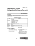
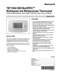
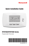
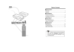
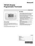
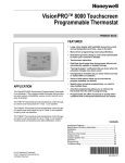
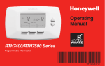
R
R
Installation
Guide
53DFS250-HW Thermostat
System Types
• Cool Only (single stage)
• Heat Pump (with electric heat)
CAUTION: ELECTRICAL HAZARD
Can cause electrical shock or equipment damage. Disconnect power before
beginning installation.
MERCURY NOTICE: If this product is replacing a control that contains mercury in
a sealed tube, do not place the old control in the trash. Contact your local waste
management authority for instructions regarding recycling and proper disposal.
Must be installed by a trained, experienced technician. Read these instructions
carefully. Failure to follow these instructions can damage the product or cause a hazardous
condition.
Select Thermostat Location
Select a location for the thermostat about 5 ft (1.5m) above the floor in an area with good air
circulation at average temperature.
Do not install the thermostat where it can be affected by:
• Drafts or dead spots behind doors
and in corners.
• Hot or cold air from ducts.
YES
• Radiant heat from sun or
appliances.
NO
NO
NO
• Concealed pipes and chimneys.
5 FEET
[1.5 METERS]
• Unheated (uncooled) areas such
as an outside wall behind the
thermostat.
M22258
® U.S. Registered Trademark.
US Patent No. 7,114,554, 7,181,317, 7,225,054, 7,274,972, 7,636,604,
7,693,582 and other patents pending.
All rights reserved.
69-2565-05
Installation Guide
Wallplate installation
1. Separate wallplate from
thermostat. Grasp top and bottom
of wallplate and pull to remove
from thermostat.
:$//3/$7(
:,5(+2/(
2. Install the wallplate as shown
below.
Drill 3/16” holes for drywall.
Drill 7/32” holes for plaster.
7+(50267$7
Wire hole
0
Mounting
screws
Wall anchors
M32487
Power options
24 VAC
C
3.0 VDC
H2
G1
NOT
USED
Y
G2
O
S1
RC
S2
R
M32488
M28101
For 24VAC primary power, connect common
side of transformer to “C” terminal.
69-2565—05
Install two AA alkaline batteries on the
back of the thermostat as marked
2
53DFS250-HW
Wiring
Push excess wire back into wall opening.
Plug wall opening with non-flammable
insulation.
Leave the metal jumper wire between
RC and R.
SCREW
INSERT WIRES
THEN TIGHTEN SCREWS
WIRE HOLE
C
H2
G1
NOT
USED
Y
G2
O
S1
RC
S2
R
M32489A
Terminal Designations:
R
Rc
C
H2
Y
G1
G2
O
S1
S2
24 Volt power
Not used [1]
24 Volt common
2nd stage heat (electric heat)
Compressor
Low speed fan
High speed fan
Reversing valve for heat pumps
Remote sensor or remote setback [2]
Remote sensor or remote setback [2]
Notes
[1] Leave the metal jumper wire in place between Rc and R.
[2] Sensor wire must have a cable separate from the thermostat control cable.
3
69-2565—05
Installation Guide
Wiring
Heat Pump with Electric Heat wiring.
C
G1
Y
O
RC
R
H2
NOT
USED
1
FACTORY INSTALLED JUMPER.
2
JUMPER WIRE (O TO Y1) REQUIRED
WHEN HEAT PUMP INDOOR IS USED
WITH COOLING ONLY OUTDOOR UNIT.
WIRE IS FIELD SUPPLIED.
G2
S1
S2
1
INDOOR TEMPERATURE
SENSOR/REMOTE
SETBACK/CHANGEOVER
PIPE SENSOR
2
H2 H1 W2 C O R Y Y1 G1 G2
G3
UNIT TERMINAL BLOCK
AIR SWEEP
FUNCTION
(NOT AVAILABLE)
HIGH FAN
LOW FAN
COMPRESSOR
24V POWER
REVERSIBLE VALVE
COMMON
NOT USED
NOT USED
2ND STAGE HEAT
(ELECTRIC HEAT)
M32490A
Cool only wiring.
1
C
G1
Y
RC
R
FACTORY INSTALLED JUMPER.
H2
NOT
USED
G2
S1
S2
1
INDOOR TEMPERATURE
SENSOR/REMOTE
SETBACK/CHANGEOVER
PIPE SENSOR
H2 H1 W2 C O R Y Y1 G1 G2
UNIT TERMINAL BLOCK
AIR SWEEP
FUNCTION
(NOT AVAILABLE)
HIGH FAN
LOW FAN
NOT USED
COMPRESSOR
24V POWER
NOT USED
COMMON
NOT USED
NOT USED
NOT USED
69-2565—05
G3
M32495
4
53DFS250-HW
Sensor wiring for temperature averaging
Wiring four TR21 (20K ohm) Sensors.
Wiring two TR21 (20K ohm) Sensors and
one TR21-A (10K ohm) Sensor to provide a
temperature averaging network
SUBBASE
S1
TR21
S2
SUBBASE
S1
TR21
T
T
T
TR21
T
T
TR21
S2
1
TR21
T
T
T
T3
T4
T
TR21-A
TR21
T
T
T
M27481
1 THE TR21-A IS A 10K OHM SENSOR.
Wiring two TR21-A (10K ohm) Sensors to
provide a temperature averaging network.
Wiring four C7189U (10K ohm) Sensors to
provide a temperature averaging network.
SUBBASE
SUBBASE
S1
S1
S2
1
T4
T3
1
TR21-A
M27483
T4
S2
C7189
C7189
C7189
C7189
T3
1
TR21-A
1 THE TR21-A IS A 10K OHM SENSOR.
1
M27482
WIRES MUST HAVE A CABLE SEPARATE
FROM THE THERMOSTAT CABLE.
M27432
5
69-2565—05
Installation Guide
Remove tab and mount thermostat
Remove tab.
WALL
M28102
Align pins on back of thermostat with
slots in wallplate, then push gently
until thermostat snaps into place.
M23024
Set date and time
Month Year Date
Press GO BACK and
NEXT to select the
Month, Year, Date,
or Time function.
Tue
PM
Go Back
Next
Press st to
change the
Month, Year, Date,
or Time setting.
Done
Done
M32496
Press DONE to save changes.
Press DONE to save and exit.
Installer setup
1.
Press SYSTEM and FAN.
2.
Press and hold SYSTEM
and DONE until the
display changes.
System Auto Fan Auto
System & Fan
FanUseEdit
Done
System Auto Fan Auto
System & Fan
FanUseEdit
Done
Function
3.
Setting
Change settings as required (see pages 7-9).
Press GO BACK and NEXT to select the function.
AM
Press st to change the setting.
Press DONE to save changes.
Go Back
Next
View
Clock & More
Done
M32497
69-2565—05
6
53DFS250-HW
Installer setup
Setup
Number
Setup Name
Settings & Options (factory default in bold)
0120
Date (Year Upper)
20 (2011-2078)
21 (2101-2178)
0130
Date (Year Lower)
08 (2008)
[Other options: 00-99]
0140
Date (Month)
6 [Other options: 1-12]
0150
Date (Day)
15 [Other options: 1-31]
0160
Schedule Options
4 Programmable
0 Non-programmable
0170
System Selection
1 Cooling only
2 Heat pump plus electric heat
0185
Pre-occupancy Purge
Duration
0
No duration
[Other options: 1, 2, or 3 hours]
0220
Cycles Per Hour (CPH)
for first stage cooling/
compressor
3
Recommended for most compressors
[Other options: 1, 2, 4, 5 or 6 CPH]
0270
Cycles Per Hour (CPH) for
heating first and second
stage
9
Recommended
[Other options: 1–12 CPH]
0280
Continuous Backlight
0No
1Yes
0300
Changeover
1 Auto
0
Manual
0310
Deadband
3
3°F (2.0°C)
[Options: 2–9 °F (1.5–5.0°C)]
0320
Temperature Indication
Scale
0
1
°F
°C
0330
Daylight Saving Time
1
0
ON
OFF
0340
Remote Temp Sensor/
Remote Setback/
Changeover Input
0None
1 Remote 10K Indoor
2 Remote 20K Indoor
0340
(Nonprogrammable)
Remote Temp Sensor/
Remote Setback/
Changeover Input
0None
1 Remote 10K Indoor
2 Remote 20K Indoor
5 Remote Setback, normally open
6 Remote Setback, normally closed
0341
Delay for Remote Setback
0
2
No Delay
2 Minute Delay
0342
Override Option (only
available in nonprogrammable mode)
1
0
Override
No Override
0343
Unoccupied Heating
Setpoint (only when remote
setback enabled)
60 60°F (15.5°C)
[Options: 50–65 °F (10–18°C)]
Continued on next page
7
69-2565—05
Installation Guide
Installer setup
Setup
Number
Setup Name
Settings & Options (factory default in bold)
0346
Unoccupied Cooling
Setpoint (only when remote
setback is enabled)
80 80°F (27°C)
[Options: 75–90 °F (24–32°C)]
0347
Fan Ramping
1
0
ON
OFF (Lo, Med, Hi)
0348
Fan Mode
0
1
User can choose Cycle or Constant 3 speed:
Low, Med, High, Auto
Cycle Only - Auto only
0349
Auto Fan Reset
0
1
2
OFF
Reset back to Auto after 2 hours
Reset back to Auto after 4 hours
0535
Temporary Occupied
Duration Limit
3
hours
[Other options: 0–12 hours]
0540
Number of Periods
4
2
4 Periods
2 Periods
0580
Minimum Compressor Off
Time
3
4
5
3 minutes
4 minutes
5 minutes
0600
Heat Temperature Range
Stops
90 90°F (32°C)
[Options: 40–90°F (4–32°C)]
0610
Cool Temperature Range
Stops
50 50°F (10°C)
[Options: 50–99°F (10–37°C)]
0640
Clock Format
12 12 Hour
24 24 Hour
0650
Extended Fan-on time Heat
0 Off
90 90 seconds
0660
Extended Fan-on time Cool
0 Off
40 40 seconds
0670
Keypad Lockout
0
1
2
3
4
Unlocked
Partial Lockout 1: Locks out schedule and system
changes
Partial Lockout 2: Locks out schedule, system,
and fan changes
Partial Lockout 3: Locks out schedule, system,
fan, and up/down arrow changes
Fully Locked: Entire interface locked/non-functional
0680
Temperature Control Heat
2Standard
1 Less Aggressive
3 More Aggressive
0685
Recovery Heat Ramp Rate
5
0690
Temperature Control Cool
2Standard
1 Less Aggressive
3 More Aggressive
69-2565—05
5°F (2.8°C)/hour
[Options: 0–20°F (0–11°C)]
8
Continued on next page
53DFS250-HW
Installer setup
Setup
Number
Setup Name
Settings & Options (factory default in bold)
0695
Recovery Cool Ramp Rate
3
3°F (1.7°C)/hour
[Options: 0–20°F (0–11°C)]
0700
Temperature Display Offset
0
0°F (0.0°C)
[Options: -3–3°F (-1.5–3°C)]
0710
Restore Factory Defaults
0No
1Yes
0720
Screen Display
2
0
1
Display Both
Display Room Temperature
Display Setpoint
Installer system test
Test
number
During installer setup, press NEXT
repeatedly until “Test” appears.
TEST1
AM
Go Back
Next
System
status
AM
View
Clock & More
Done
Go Back
Next
Press NEXT to
select test
View
Clock & More
Done
Press st to
change status
M32498
Press DONE to terminate testing.
System test
System status
1
Installer Test Cool
0
1
Off
Cool Stage 1 On
2
Installer Test Fan
0 Off
1 Low
2Med
3 High
3
Installer Test Heat
0
1
2
Off
Heat Stage 1 On
Heat Stage 2 On
4
Installer Test EM Heat
0
1
Off
EM Heat On
9
CAUTION: EQUIPMENT
DAMAGE HAZARD.
Compressor protection is
bypassed during testing.
To prevent equipment
damage, avoid cycling
the compressor quickly.
69-2565—05
Installation Guide
Special functions
Fan Sequence Operations (Setup Function 0347, 0348, 0349): The thermostat comes factory default
with the fan ramping algorithm enabled (ISU 347). This gives the user the ability to select Auto-LoMed-Hi option in ISU 348 or Auto only option in ISU 348. Auto sets the thermostat into the fan ramping
algorithm mode and automatically sets the sufficient speed for PI control. Auto also automatically
shuts the fan off when there is not a call for heating or cooling. If the user decides to disable ISU 347,
then the fan will only have Lo-Med-Hi option available.
If ISU 347 is not enabled, then ISU 348 does not appear as a user selection choice.
If ISU 347 is enabled, then ISU 349 is available as a selection choice. The user can select either a 2
hour or 4 hour timer fan reset function. The fan will reset from a constant speed to auto mode after
the time period expires. If ISU 347 is not enabled, then ISU 349 does not appear as a user selection
choice.
Auto Changeover (Setup Function 0300): When set to Auto, the thermostat automatically selects heating or cooling depending on the indoor temperature.
Compressor Protection (Setup Function 0580): Forces the compressor to wait a few minutes before
restarting, to prevent damage. During this time, the message “Wait” flashes on the display.
Special Programmable Mode Functions
Installer Setup 0160 allows the thermostat to be configured for either a mode with a programmable 7
day schedule or as a non-programmable thermostat.
Preoccupancy purge (ISU 0185): This feature is available only when the thermostat is configured as
a programmable schedule and when a fan is used. The fan will run 1-3 hours before the occupied
schedule starting time to circulate air.
Override Button, Temporary Override (Duration Limit ISU 0535): While in the programmable schedule mode, an override button is available to perform temporary override control. The default override
time can be configured through ISU 0535. Lockout configuration via ISU 0670 can provide restrictions
on access to setpoint changes, system changes, and schedule changes.
No remote setback: The remote setback feature only works in the nonprogrammable mode.
Special Non-Programmable Mode Functions
Override (Optional): The override feature is optional in the non-programmable mode. The override
can be configured through ISU 0342. When the override is activated in the non-programmable mode it
will temporarily override to a new setpoint until the end time expires.
Remote Setback: Remote Setback is available (ISU 0340). Occupancy sensors, manual time clock
inputs, and DDC night setback can be used to provide inputs to setback the thermostat. Unoccupied
heating (ISU 0343) and unoccupied cooling (ISU 0346) setpoints are available to configure the setback
setpoints.
69-2565—05
10
53DFS250-HW
Troubleshooting
Symptom
Possible Cause
Action
Display does not come
on.
Thermostat is not being
powered.
Check for 24 Vac between C and R. Check that AA
batteries are installed correctly and are good.
Temperature settings
do not change.
The upper or lower temperature
limits were reached.
Check temperature setpoints. Check Installer Setup
Numbers 0600 and 0610; modify as needed.
The keypad is fully locked.
Check Installer Setup Number 0670 to change
keypad locked options.
Thermostat minimum off-time is
activated.
Wait up to five minutes for the system to respond.
System selection not set to Heat
or Cool.
Set system Selection to correct position.
System type Selection is
incorrect.
Check Installer Setup Number 0170 and make sure
correct System type is chosen.
Heating equipment failure.
Check for 24 Vac at the equipment on the secondary
side of the transformer between power and
common. If voltage is not present, check the heating
equipment to find the cause of the problem.
Check for 24 Vac between the heat terminal (Y and
H2) and transformer common. If 24 Vac is present,
the thermostat is functional. Check the heating
equipment to find the cause of the problem.
Loose or broken wire
connection between thermostat
and heating equipment.
Check for 24 Vac between the heat terminal (Y
and H2) and transformer common. If voltage is not
present, check wire connection (loose or broken)
between the thermostat and the heating equipment.
Cooling equipment failure.
Check for 24 Vac at the equipment on the secondary
side of the transformer between power and
common. If voltage is not present, check the cooling
equipment to find the cause of the problem.
Check for 24 Vac between the cool terminal (Y)
and transformer common. If 24 Vac is present,
the thermostat is functional. Check the cooling
equipment to find the cause of the problem.
Loose or broken wire
connection between thermostat
and cooling equipment.
Check for 24 Vac between the cool terminal (Y)
and transformer common. If voltage is not present,
check the wire connection (loose or broken)
between the thermostat and the cooling equipment.
Heat On is not in the
display.
System setting is not set
to Heat and/or temperature
setting is not set above room
temperature.
Set the system setting to Heat and set the
temperature setting above the room temperature.
Cool On is not in the
display.
System setting is not set to
Cool and/or the temperature
setting is not set below room
temperature.
Set the system setting to Cool and set the
temperature setting below the room temperature.
Wait is in the display.
Compressor minimum off timer
is active.
Wait up to five minutes for the cooling or heating
(heat pump) equipment to turn on.
Heating or cooling
does not come on.
Heat does not turn on
(Heat On is solid in the
display).
Cooling does not turn
on (Cool On is solid in
the display).
11
69-2565—05
Installation Guide
Accessories & replacement parts
Please contact your distributor to order replacement parts.
Indoor Sensor.......................................................... Part Number P350-ISEN-CM20
Indoor Sensor.......................................................... Part Number P350-ISEN-CM10
Duct Probe............................................................... Part Number P350-PRB01
Indoor Sensor.......................................................... Part Number P350-ISEN-R340
Coverplate*.............................................................. Part Number P350-CP-MULTI
*(Use to cover marks left by old thermostats.)
Specifications
Temperature Ranges
• Heat: 40° to 90°F (4.5° to 32°C)
• Cool: 50° to 99°F (10° to 37°C)
Operating Ambient Temperature
• 0° to 120°F (-18° to 48.9°C)
Shipping Temperature
• -30° to 150°F (-34° to 66°C)
Electrical Ratings
Terminal
Voltage (50/60Hz)
Running Current
H2 Heating
20-30 Vac
0.02-1.0 A
Y Cooling
20-30 Vac
0.02-1.0 A
G Fan
20-30 Vac
0.02-0.6 A
Operating Relative Humidity
• 5% to 90% (non-condensing)
Physical Dimensions
• 3-3/4” H x 6” W x 1-3/8” D
• 95 mm H x 152 mm W x 35 mm D
R
® U.S. Registered Trademark.
US Patent No. 7,114,554, 7,181,317, 7,225,054, 7,274,972, 7,636,604,
7,693,582 and other patents pending.
69-2565—05 M.S. Rev. 05-11
Printed in U.S.A.