1
BES-961BC
BES-1261BC
SERVICE MANUAL
Please read this manual before making any adjustments.
9 NEEDLE 6 HEAD EMBROIDERY MACHINE (SA TYPE)
12 NEEDLE 6 HEAD EMBROIDERY MACHINE (SA TYPE)
Precautions
• Unauthorized commercial or industrial use of trademarks or copyrighted materials (such as
paintings, drawings, photos, logos, etc.) owned by other companies or persons is illegal. The
use of such materials without the permission of their owners may result in criminal or civil liability.
• This manual may be subsequently modified without prior notice.
• Brother Industries, Ltd. shall assume no responsibility for any consequences of using this manual.
This service manual is intended for BES-961BC, 1261BC; be sure to read the BES-961BC, 1261BC
instruction manual before this manual.
Carefully read the “SAFETY INSTRUCTIONS” below and the whole of this manual to understand
this product before you start maintenance.
As a result of research and improvements regarding this product, some details of this manual may
not be the same as those for the product you purchased.
If you have any questions regarding this product, please contact a Brother dealer.
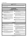
SAFETY INSTRUCTIONS
1 Safety indications and their meanings
This instruction manual and the indications and symbols that are used on the machine itself are provided
in order to ensure safe operation of this machine and to prevent accidents and injury to yourself or other
people. The meanings of these indications and symbols are given below.
Indications
DANGER
The instructions which follow this term indicate situations where failure
to follow the instructions will almost certainly result in death or severe
injury.
CAUTION
The instructions which follow this term indicate situations where failure
to follow the instructions could cause injury when using the machine
or physical damage to equipment and surroundings.
Symbols
................. This symbol (
) indicates something that you should be careful of.
The picture inside the triangle indicates the nature of the caution that must be
taken. (For example, the symbol at left means "beware of injury".)
................. This symbol (
) indicates something that you must not do.
................. This symbol (
) indicates something that you must do.
The picture inside the circle indicates the nature of the thing that must be done.
(For example, the symbol at left means "you must make the ground connection".)
BES-961BC.1261BC
i
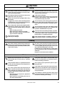
2 Notes on safety
DANGER
Wait at least 5 minutes after turning off the power switch and disconnecting the power cord from the wall
outlet before opening the face plate of the control box. Touching areas where high voltages are present can
result in severe injury.
CAUTION
Environmental requirements
Use the sewing machine in an area which is free
from sources of strong electrical noise such as
high-frequency welders.
Sources of strong electrical noise may cause
problems with correct operation.
Any fluctuations in the power supply voltage
should be within ±10% of the rated voltage for
the machine.
Voltage fluctuations which are greater than this
may cause problems with correct operation.
The power supply capacity should be greater than
the requirements for the sewing machine's electrical consumption.
Insufficient power supply capacity may cause
problems with correct operation.
The ambient temperature should be within the range
of 5°C to 35°C during use.
Temperatures which are lower or higher than this
may cause problems with correct operation.
The relative humidity should be within the range of
45% to 85% during use, and no dew formation
should occur in any devices.
Excessively dry or humid environments and dew
formation may cause problems with correct operation.
Avoid exposure to direct sunlight during use.
Exposure to direct sunlight may cause problems
with correct operation.
In the event of an electrical storm, turn off the power
and disconnect the power cord from the wall outlet.
Lightning may cause problems with correct operation.
Installation
Machine installation should only be carried out
by a qualified technician.
Contact your Brother dealer or a qualified electrician for any electrical work that may need to
be done.
The sewing machine weighs more than 720 kg.
The installation should be carried out by a lift or
a crane.
Do not connect the power cord until installation
is complete, otherwise the machine may operate
if the start switch is pressed by mistake, which
could result in injury.
Be sure to connect the ground. If the ground connection is not secure, you run a high risk of receiving a serious electric shock, and problems
with correct operation may also occur.
When securing the cords, do not bend the cords
excessively or fasten them too hard with staples,
otherwise there is the danger that fire or electric
shocks could occur.
Be sure to wear protective goggles and gloves
when handling the lubricating oil or grease, so that
no oil or grease gets into your eyes or onto your
skin, otherwise inflammation can result.
Furthermore, do not drink the oil or grease under
any circumstances, as they can cause vomiting and
diarrhoea.
Keep the oil out of the reach of children.
Avoid setting up the sewing machine near sources
of strong electrical noise such as high-frequency
welding equipment.
If this precaution is not taken, incorrect machine
operation may result.
Secure the machine with the casters when installing it so that it will not move by placing the leveling seat on the sound floor.
ii
BES-961BC.1261BC
CAUTION
Sewing
This sewing machine should only be used by operators who have received the necessary training in safe use beforehand.
Secure the machine with the casters when installing it so that it will not move by placing the leveling seat on the sound floor.
The sewing machine should not be used for any
applications other than sewing.
Table may be damaged.
Attach all safety devices before using the sewing
machine. If the machine is used without these devices attached, injury may result.
Be sure to wear protective goggles when using
the machine.
If goggles are not worn, there is the danger that if
a needle breaks, parts of the broken needle may
enter your eyes and injury may result.
Turn off the power switch at the following times,
otherwise the machine may operate if the start
switch is pressed by mistake, which could result
in injury.
• When threading the needle
• When replacing the bobbin and needle
• When not using the machine and when leaving the machine unattended
Do not get on the table.
Table may be damaged.
Do not touch any of the moving parts or press any
objects against the machine while sewing, as this
may result in personal injury or damage to the machine.
Do not touch the pulse motor and sewing machine
bed section during operation or for 30 minutes after
operation. Otherwise burns may result.
If an error occurs in machine operation, or if abnormal noises or smells are noticed, immediately turn
off the power switch. Then contact your nearest
Brother dealer or a qualified technician.
If the machine develops a problem, contact your
nearest Brother dealer or a qualified technician.
Cleaning
Turn off the power switch before starting any
cleaning work, otherwise the machine may operate if the start switch is pressed by mistake, which
could result in injury.
Be sure to wear protective goggles and gloves
when handling the lubricating oil or grease, so that
no oil or grease gets into your eyes or onto your
skin, otherwise inflammation can result.
Furthermore, do not drink the oil or grease under
any circumstances, as they can cause vomiting and
diarrhoea.
Keep the oil out of the reach of children.
Maintenance and inspection
Maintenance and inspection of the sewing machine should only be carried out by a qualified
technician.
If the power switch needs to be left on when carrying out some adjustment, be extremely careful to
observe all safety precautions.
Ask your Brother dealer or a qualified electrician
to carry out any maintenance and inspection of
the electrical system.
Use only the proper replacement parts as specified by Brother.
Turn off the power switch and disconnect the
power cord from the wall outlet at the following
times, otherwise the machine may operate if the
treadle is depressed by mistake, which could result in injury.
• When carrying out inspection, adjustment
and maintenance
• When replacing consumable parts such as
the rotary hook and knife.
If any safety devices have been removed, be absolutely sure to re-install them to their original positions and check that they operate correctly before
using the machine.
Any problems in machine operation which result
from unauthorized modifications to the machine
will not be covered by the warranty.
BES-961BC.1261BC
iii
This service manual gives explanations for the following two models:
• BES-961BC (9 needle)
• BES-1261BC (12 needle)
Description limited to either model is given with the appropriate model name.
Before reading this manual, check your machine's model name.
CONTENTS
Chapter 1 Mechanical Descriptions ............................................................. 1
1. Feed guide mechanism .................................................................................................................... 1
2. Crank shaft mechanism ................................................................................................................... 2
3. Lower shaft and rotary hook mechanisms .................................................................................... 3
4. Thread trimmer mechanism ............................................................................................................. 4
5. Thread take-up mechanism .............................................................................................................. 5
6. Needle bar mechanism ..................................................................................................................... 6
7. Needle bar flip-up mechanism ........................................................................................................ 7
8. Presser foot lifter mechanism ......................................................................................................... 8
9. Thread wiper mechanism ................................................................................................................. 9
10. Cap frame device .......................................................................................................................... 10
Chapter 2 Parts Replacement and Adjustment ........................................ 11
1. Replacing and adjusting the machine heads .............................................................................. 11
2. Removing the needle bar case ...................................................................................................... 18
3. Replacing and adjusting the thread take-up lever ...................................................................... 19
4. Replacing the needle bar ............................................................................................................... 21
5. Replacing the jump bracket ........................................................................................................... 22
6. Replacing and adjusting the jump solenoid ................................................................................ 23
7. Replacing the rotary encoder and the sensor PCB .................................................................... 24
8. Replacing timing belt X .................................................................................................................. 25
9. Replacing timing belt Y .................................................................................................................. 26
10. Replacing the driving wire ........................................................................................................... 28
11. Replacing and adjusting the presser lifter parts ...................................................................... 29
11-1. Presser foot ........................................................................................................................... 29
11-2. Presser foot shaft .................................................................................................................. 29
11-3. Replacing and adjusting the W retracting lever and the RET motor lever .......................... 31
11-4. Replacing and adjusting the pulse motor ............................................................................. 32
12. Replacing and adjusting the gears related to the needle bar flip-up mechanism ................ 33
13. Replacing and adjusting the potentiometer .............................................................................. 37
BES-961BC.1261BC
14. Replacing and adjusting the movable and fixed knives .......................................................... 40
15. Replacing and adjusting the lower shaft module ..................................................................... 41
16. Replacing the presser foot switch .............................................................................................. 45
17. Replacing and adjusting the solenoid that controls pulley ..................................................... 46
Chapter 3 Adjustment .................................................................................. 47
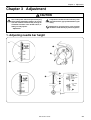
1. Adjusting needle bar height .......................................................................................................... 47
2. Adjustment of clearance between needle and rotary hook ....................................................... 51
3. Adjustment of timing between needle and rotary hook ............................................................. 52
4. Adjusting the clearance between the rotary hook and the inner rotary .................................. 53
5. Adjustment of presser foot height ................................................................................................ 54
6. Adjustment of thread trimmer ....................................................................................................... 55
6-1. Attaching the fixed knife ......................................................................................................... 55
6-2. Checking the movable knife position ...................................................................................... 55
7. Adjusting the thread wiper ............................................................................................................ 58
8. Adjusting the jump solenoid ......................................................................................................... 59
9. Adjusting the switch ....................................................................................................................... 60
10. Adjusting the timing belt tension ............................................................................................... 64
10-1. Timing belt X ......................................................................................................................... 64
10-2. Timing belt Y ......................................................................................................................... 65
11. Adjusting the driving wire ........................................................................................................... 68
12. Adjusting the Y-carriage ............................................................................................................... 69
12-1. When the sliding resistance of the Y-carriage is below the standard value ....................... 70
12-2. When the sliding resistance of the Y-carriage is over the standard value even after
adjustment 12-1 ................................................................................................................... 71
12-3. When the sliding resistance of the Y-carriage is over the standard value ......................... 72
12-4. When linear guide 505L, which is attached to machine head No.3, is not parallel
to the top surface of the bed ............................................................................................... 72
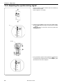
13. Adjusting the rotary encoder and sensor PCB ......................................................................... 73
13-1. Adjusting the machine stop position signal .......................................................................... 73
13-2. Adjusting the synchronizing signal ....................................................................................... 74
14. Adjusting the bobbin winder ....................................................................................................... 75
14-1. Positioning the bobbin winder claw ...................................................................................... 75
14-2. Positioning the bobbin presser ............................................................................................. 75
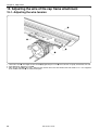
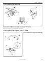
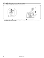
15. Adjusting the wire of the cap frame attachment ...................................................................... 76
15-1. Adjusting the wire tension ..................................................................................................... 76
15-2. Adjusting the feed roller ........................................................................................................ 77
15-3. Adjusting cap support plates L and R .................................................................................. 77
15-4. Adjusting the presser foot height .......................................................................................... 78
BES-961BC.1261BC
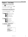
Chapter 4 Test Mode .................................................................................... 79
1. Entering into the test mode ........................................................................................................... 79
2. Selecting the test mode menu ...................................................................................................... 79
3. Function of the test mode ............................................................................................................. 81
3-1. Thread trimmer adjustment ..................................................................................................... 81
3-2. Needle bar moving test .......................................................................................................... 81
3-3. Carriage sensor test ............................................................................................................... 83
3-4. Encoder signal test ................................................................................................................. 84
3-5. Hook timing adjustment .......................................................................................................... 85
3-6. Presser foot test ..................................................................................................................... 85
3-7. LED SW test ........................................................................................................................... 86
3-8. Port/voltage check .................................................................................................................. 87
3-9. Solenoid test ........................................................................................................................... 88
3-10. Main shaft motor rotation test ............................................................................................... 89
3-11. Detailed version of CPU in the machine .............................................................................. 89
3-12. Checking and clearing BC errors ......................................................................................... 90
3-13. Lower shaft sensor test ........................................................................................................ 92
3-14. Lower shaft module test ....................................................................................................... 94
3-15. Power supply voltage adjustment ......................................................................................... 95
Chapter 5 Upgrading version of machine program ................................. 96
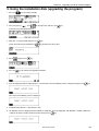
1. Downloading the file ....................................................................................................................... 96
2. Creating the installation disk ........................................................................................................ 96
3. Using the installation disk (upgrading the program) ................................................................. 97
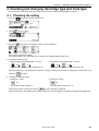
4. Checking and changing the bridge type and hook type ............................................................ 99
4-1.
Checking the setting ............................................................................................................ 99
4-2.
Changing the bridge type .................................................................................................. 100
4-3.
Changing the hook type ..................................................................................................... 102
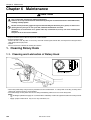
Chapter 6 Maintenance .............................................................................. 104
1. Cleaning Rotary Hook .................................................................................................................. 104
1-1.
Cleaning and Lubrication of Rotary Hook ......................................................................... 104
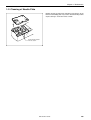
1-2.
Cleaning of Needle Plate ................................................................................................... 105
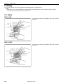
2. Oiling .............................................................................................................................................. 106
2-1. Head ...................................................................................................................................... 106
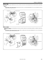
3. Greasing ......................................................................................................................................... 108
3-1. Head ...................................................................................................................................... 108
3-2. Feed Guide Section .............................................................................................................. 112
3-3. Greasing the lower shaft module .......................................................................................... 113
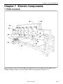
Chapter 7 Electric Components ............................................................... 115
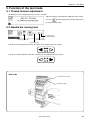
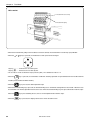
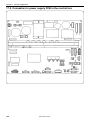
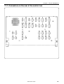
1. PCBs locations .............................................................................................................................. 115
2. Replacing the PCBs in the control box ...................................................................................... 117
2-1. Removing and reattaching the control box ........................................................................... 117
BES-961BC.1261BC
2-2. Removing and reattaching the control box cover ................................................................ 117
2-3. Replacing the main PCB ...................................................................................................... 118
2-4. Replacing the power supply PCB ......................................................................................... 119
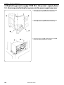
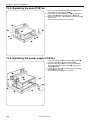
3. Replacing power supply PCB B in the power supply base ..................................................... 120
3-1. Removing and attaching the leg cover and the power supply base cover ......................... 120
3-2. Replacing power supply PCB B in the power supply base ................................................. 121
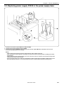
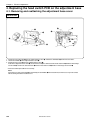
4. Replacing the head switch PCB on the adjustment base ....................................................... 122
4-1. Removing and reattaching the adjustment base cover ....................................................... 122
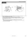
4-2. Replacing the head switch PCB ........................................................................................... 124
4-3. Removing the TR breakage sensor PCB ............................................................................. 125
5. Replacing the head PCB .............................................................................................................. 127
6. Replacing the BC PCB ................................................................................................................. 128
7. Replacing the BC sensor PCB .................................................................................................... 129
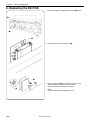
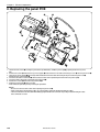
8. Replacing the panel PCB ............................................................................................................. 130
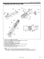
9. Replacing the Y-feed sensor PCB ............................................................................................... 131
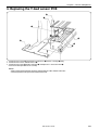
10. Replacing the X-feed sensor PCB ............................................................................................ 132
11. Replacing the retracting bed sensor PCB ............................................................................... 133
12. Replacing the thread trimming sensor PCB ............................................................................ 134
13. Replacing the cooling fans ........................................................................................................ 135
13-1. Replacing the control box fan ............................................................................................. 135
13-2. Replacing the main PCB fan .............................................................................................. 136
13-3. Replacing the power supply PCB fan ................................................................................ 136
14. Fuses ............................................................................................................................................ 137
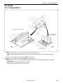
14-1. Fuse positions ..................................................................................................................... 137
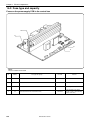
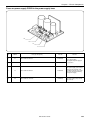
14-2. Fuse type and capacity ...................................................................................................... 138
14-3. Replacing the fuses ............................................................................................................ 140
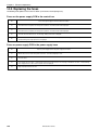
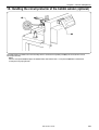
15. Handling the circuit protector of the bobbin winder (optional) ............................................ 141
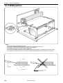
16. P-ROM position ........................................................................................................................... 142
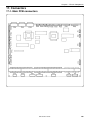
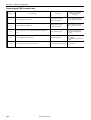
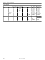
17. Connectors .................................................................................................................................. 143
17-1. Main PCB connectors ......................................................................................................... 143
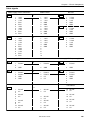
17-2. Connectors in power supply PCB in the control box ......................................................... 154
17-3. Connectors in power supply PCB B in power supply base ............................................... 161
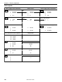
17-4. Connector in panel PCB ..................................................................................................... 162
17-5. Connectors in BC PCB ....................................................................................................... 164
17-6. Connectors in head PCB .................................................................................................... 167
17-7. Connectors on the rear of the control box ......................................................................... 171
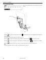
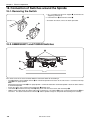
18. Connection of Switches around the Spindle .......................................................................... 174
18-1. Removing the Switch ......................................................................................................... 174
18-2. EMERGENCY and POWER Switches ............................................................................... 174
18-3. Switch Cover ...................................................................................................................... 175
18-4. Change Color Section ........................................................................................................ 176
BES-961BC.1261BC
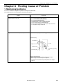
Chapter 8 Finding Cause of Problem ...................................................... 177
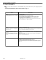
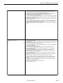
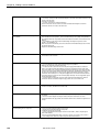
1. Mechanical problems .................................................................................................................... 177
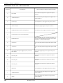
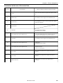
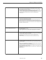
2. Electrical parts .............................................................................................................................. 178
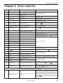
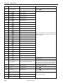
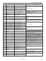
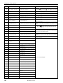
Chapter 9 Error code list ........................................................................... 187
Test mode menu list ..................................................................................... 193
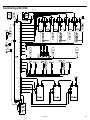
Control Block Diagram (BES-961BC) ......................................................... 194
Control Block Diagram (BES-1261BC) ....................................................... 195
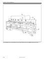
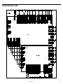
Control Box (BES-961BC, 1261BC) ............................................................. 196
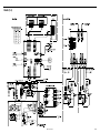
Heads (1-6)..................................................................................................... 197
BES-961BC.1261BC
Chapter 1 Mechanical Descriptions
Chapter 1 Mechanical Descriptions
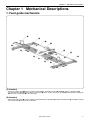
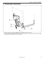
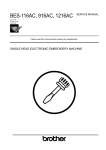
1. Feed guide mechanism
o
r
e
q
u
!0
o
!1
w
!0
y
t
!2
!1
r
u
i
[Y direction]
• When the Y-pulse motor qstarts, its motion is transmitted to connecting shafts A w and B e, and the Y-driving shaft r.
• The rail connecting plate y secured to the Y-feed frame t moves the wire, and the Y-carriage i attached to the Y-timing belts
u moves the Y-feed frame t in the Y-direction.
[X direction]
• When the X-pulse motor o starts, its motion is transmitted to the X-timing belt !0, and the X-feed bracket !1, resulting in causing
the X-feed frame !2 to move in the X-direction.
BES-961BC.1261BC
1
Chapter 1 Mechanical Descriptions
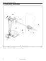
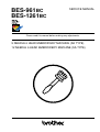
2. Crank shaft mechanism
w
e
e
q
r
t
y
When the motor q starts, pulley B w is rotated via the V-belt, resulting in causing the driving shaft e to rotate the thread take-up
cam r, the needle bar driving cam t, and the work clamp cam y.
2
BES-961BC.1261BC
Chapter 1 Mechanical Descriptions
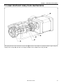
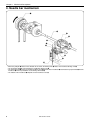
3. Lower shaft and rotary hook mechanisms
q
w
e
t
r
When pulley B and the crank shaft rotate, the pulse motor q of the lower shaft module is synchronized with the upper shaft by the
coupling hub assembly R w, and rotates the coupling hub e, the lower shaft r, and the rotary hook t.
BES-961BC.1261BC
3
Chapter 1 Mechanical Descriptions
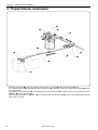
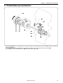
4. Thread trimmer mechanism
r
e
w
t
q
o
t
i
y
u
!0
• When the pulse motor q receives the signal for the final stitch, C TR gear w rotates, and A TR gear e rocks.
• The motion of TR gear A e is transmitted to connecting block TR r, resulting in causing the two TR connecting rods t to move
to the right and left.
• The motion of TR connecting rods t is transmitted to the thread trimmer lever y, resulting in causing TR connecting rod assys
B u and C i to move back and forth.
• When TR connecting rod assys B u and C i move back and forth, the movable knife o and the fixed knife !0 engage with each
other to trim the thread.
4
BES-961BC.1261BC
Chapter 1 Mechanical Descriptions
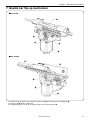
5. Thread take-up mechanism
q
u
y
w
t
r
e
• When pulley B q rotates in the direction of the arrow, the motion is transmitted to the crank shaft w, and the thread take-up
driving cam e rotates.
• The thread take-up driving cam e rocks the lever t via the roller of the TR take-up driving lever assembly r.
• The lever t moves the thread take-up lever u via the thread take-up boss y.
BES-961BC.1261BC
5
Chapter 1 Mechanical Descriptions
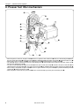
6. Needle bar mechanism
q
w
r
e
i
u
o
t
y
!0
• When the pulley B q rotates in the direction of the arrow, the driving shaft w rotates the needle bar driving cam e.
• The connecting rod r is connected to the needle bar driving cam e.
• The connecting rod r moves the needle bar driving lever t, and the base needle bar i attached to the jump bracket u and the
needle bar o move up and down via the driving connector y.
• The motion of the needle bar o depends on the needle bar case !0.
6
BES-961BC.1261BC
Chapter 1 Mechanical Descriptions
7. Needle bar flip-up mechanism
BES-961BC
t
e
w
r
q
BES-1261BC
t
r
e
w
q
• The needle bar flip-up signal is transmitted to the pulse motor q to activate bevel gears A w and B e.
The change cam r switches needle bars.
• The needle bar flip-up is sent to all six machine heads via the connecting shaft t.
BES-961BC.1261BC
7
Chapter 1 Mechanical Descriptions
8. Presser foot lifter mechanism
!1
!0
o
i
!2
r
!3
!5
q
!4
w
e
u
t
y
• When the power is turned on, the pulse motor q receives a signal, the RET motor lever w works, the W retracting lever e raises
the presser foot shaft clamp r and the presser foot t to a position decided by W motor sensor plate y and the W switch assy u.
• When sewing starts, the pulse motorq is off, and the presser foott is lowered by the retracting springi.
• The roller !0, which is attached to the presser foot driving lever o and inserted into the groove of the work clamp cam !1,
transmits the motion to the link !2
• The presser foot operating base !3 set in the link !2 and the presser foot shaft clamp r secured to the presser foot shaft !4 are
connected by the retracting spring i. They move the presser foot t up and down along the groove of the presser guide plate !5.
• When sewing is completed, the pulse motor q receives a signal, and raises the presser foot t to a position decided by W motor
sensor plate y and the W switch assy u.
• While the power is turned off, the presser foott can be raised manually by pressing the W retracting levere.
8
BES-961BC.1261BC
Chapter 1 Mechanical Descriptions
9. Thread wiper mechanism
q
w
r
t
e
• After sewing is finished, the wiper solenoid q moves the plate w in the direction of the arrow.
• The upper thread guide hook e attached to the plate w trims the upper thread. The trimmed thread is raised by the spring r,
and maintained in a position on the thread presser base t.
BES-961BC.1261BC
9
Chapter 1 Mechanical Descriptions
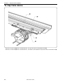
10. Cap frame device
q
e
w
r
• When the X-feed frame q moves in the direction of X, the cap frame device is rotated by the wire w.
• When the Y-feed frame e moves in the direction of Y, the motion is transmitted to the cap frame device via the fixed lever r.
10
BES-961BC.1261BC
Chapter 2 Parts Replacement and Adjustment
Chapter 2 Parts Replacement and Adjustment
CAUTION
Turn off the power switch before starting any
cleaning work, otherwise the machine may operate if the start switch is pressed by mistake,
which could result in injury.
Maintenance and inspection of the sewing machine should only be carried out by a qualified
technician.
Turn off the power switch and disconnect the
power cord from the wall outlet at the following
times, otherwise the machine may operate if the
treadle is depressed by mistake, which could result in injury.
• When carrying out inspection, adjustment and
maintenance
If the power switch needs to be left on when
carrying out some adjustment, be extremely
careful to observe all safety precautions.
Use only the proper replacement parts as specified by Brother.
If any safety devices have been removed, be
absolutely sure to re-install them to their original positions and check that they operate correctly before using the machine.
Any problems in machine operation which result from unauthorized modifications to the
machine will not be covered by the warranty.
Secure the machine when installing it so that it
will not move by placing the leveling seat on
the sound floor.
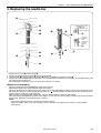
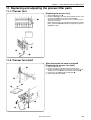
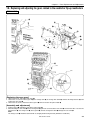
1. Replacing and adjusting the machine heads
Notes:
• Be sure to lower table F when it has been used.
• Remove all connectors and the like which are attached to the machine heads.
• Be sure to replace machine heads one by one. Do not remove two or more heads at once.
• Do not remove anything but the feed mechanism.
BES-961BC.1261BC
11
Chapter 2 Parts Replacement and Adjustment
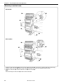
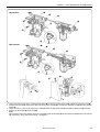
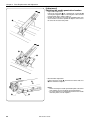
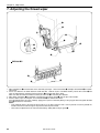
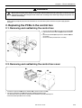
[Removing a machine head]
BES-961BC
w
q
y
r
t
e
u
BES-1261BC
q
w
y
r
t
e
u
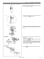
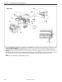
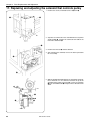
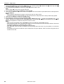
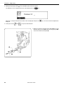
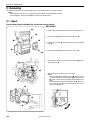
1. Remove the two connectors w from the rear of the adjustment base q. (At this time, separate cords from cord clamps.)
2. Remove screws, the cover e, and the switch cover r. (Remove the covers for remaining machine heads.)
3. Remove the four bolts y, and the needle bar case t from the head u.
Note:
When removing the switch cover r, remove switch connectors.
12
BES-961BC.1261BC
Chapter 2 Parts Replacement and Adjustment
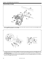
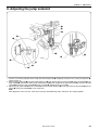
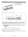
BES-961BC
u
o
i
o
!6
!7
!5
BES-1261BC
u
o
i
o
!6
!7
!5
!0
!3
!1
!2
!6
!8
!4
!9
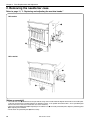
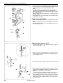
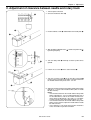
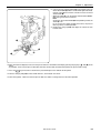
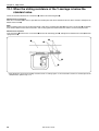
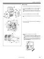
4. Loosen the fourteen bolts of the change bracket collars o securing the connecting shaft i, and pull the connecting shaft i.
5. Remove belt cover B !0, and then the connector of the rotary encoder !1. Remove the shoulder screw !3 from the encoder
bracket !2.
6. Loosen the two set screws of the inner presser collar !4 and the six bolts of the collar !5, and pull the driving shaft !6 to the left.
7. Remove the three bolts !7 and the head u.
Note:
Pull the driving shaft at the position where the zero bight needle location dog !8 and the photo-sensor !9 do not make contact
with each other. (They make contact at 80 - 120 degrees.)
BES-961BC.1261BC
13
Chapter 2 Parts Replacement and Adjustment
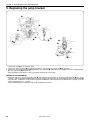
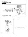
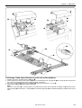
[Reassembling the head]
w
q
e
r
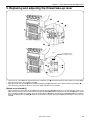
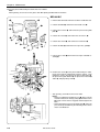
1. Hook the head q on the projections of the bridge w, make contact with the right side of the head to the spring pin e, and attach
the head q to the bridge w with the three bolts r.
t
y
t
u
!3
!2
!0
o
!1
!0
i
visor
i
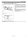
2. As shown in the figure, insert the driving shaft t from the left while passing it through the inner presser collar i, the thrust roller
bearing o, and the two thrust washers !0 so that the zero bight needle location dog y and the photo-sensor u do not make
contact with each other.
Insert the driving shaft t all the way until the visor of the bearing !2 makes contact with the end of the driving shaft bearing !3.
3. Press pulley B !1 so that it covers the driving shaft bearing !3 with the inner presser collar i, and tighten the set screw of the
inner presser collar i to eliminate end play.
14
BES-961BC.1261BC
Chapter 2 Parts Replacement and Adjustment
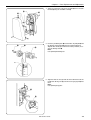
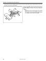
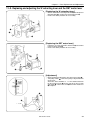
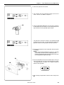
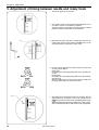
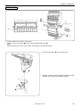
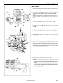
4. Attach the connector of the rotary encoder !4 to the encoder
bracket !5 using the shoulder screw !6.
!4
!5
!6
!7
!1
!3
5. Insert the positioning bar !7 into the holes of pulley B !1 and
the driving shaft bearing !3 (when the pulley indicator is
aligned with 180 degree mark of the rotary encoder) to secure the driving shaft t.
Note:
Use optional positioning bar.
180°
6. Align the hole on the right side of the head with that of the
needle bar driving cam !8, and insert the gauge pin !9 into
them.
Note:
Use optional gauge pins.
!8
!9
BES-961BC.1261BC
15
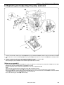
Chapter 2 Parts Replacement and Adjustment
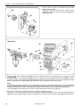
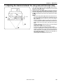
7. Align the slit of the needle bar cam !8 with that of the collar
@0, and secure the latter.
Repeat this step for all of the six heads. After this step is
completed for all heads, remove the gauge pin !9 and the
positioning bar !7.
!7
!8
@0
!9
!8
Slits
BES-961BC
@5
@4
@2
!1
@2
@3
@2
Bolt
@3
@1
!7
Needle bar
No.3
q
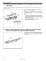
8. Install the needle bar case @1 on the head q, and insert the connecting shaft @2. Do not forget to pass it through the change
bracket collar @3.
9. At needle bar No.3, insert the positioning bar !7 from the front of the needle bar case @1 into the hole of the head q to secure the
needle bar case @1. Insert another positioning bar !7 into needle bar case of the next head, secure two change bracket collars
@3 while checking that the needle definitely falls into the hole on the needle plate attached to the bed.
Notes:
Two positioning bars !7 are required. One is inserted into the head whose needle penetration position has been determined;
the other is inserted into the head whose needle penetration position will be determined. (If both bars are used for heads whose
needle penetration position is not yet determined, you will not be able to find the correct needle penetration position.)
Turn pulley B !1 on each head to make sure that the needle will fall into the hole on the needle plate.
10.Attach covers, and insert two connectors @5 into the rear of the adjustment base @4.
At this time, be sure to attach the harnesses to the cord holder, providing an allowance for the harnesses tension between the
adjustment base set and the bridge. (If there is no allowance, the pattern to be sewn may be distorted during color change.)
16
BES-961BC.1261BC
Chapter 2 Parts Replacement and Adjustment
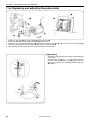
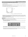
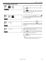
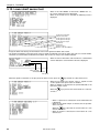
11.Turn on the power of the machine.
12.The machine starts the encoder signal test in the test mode.
Refer to "Test Mode" in chapter 4.
13.Turn the pulley to make sure that the buzzer will start to sound
becomes "H".
at 165 degrees and
165°
Encoder
14.If it does not start to sound at 165 degrees, loosen the two
screws @6 fixing the encoder adjusting plate !5 and adjust the
angle.
!5
@6
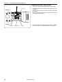
BES-961BC
15.The machine starts the needle bar case moving test in the
test mode.
Refer to "Test Mode" in chapter 4.
and the buzzer sounds
Check to see that
@8
@9
when the needle bar is No.1.
If it does not sound, loosen the set screw @8 of the potentiometer, remove the potentiometer @9 and turn the shaft for adjustment. Refer to "13. Replacing and adjusting the potentiometer" on page 37. for details.
@8
BES-1261BC
16.Press the
@8
ESC
key to return to the embroidery initial screen.
@9
BES-961BC.1261BC
17
Chapter 2 Parts Replacement and Adjustment
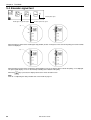
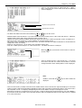
2. Removing the needle bar case
Refer to page 11, "1. Replacing and adjusting the machine heads."
BES-961BC
q
w
e
BES-1261BC
q
w
e
[Notes on assembly]
• The needle bar case q should move to the right and left easily, and a needle should be aligned with the hole in the needle plate.
(Carry out the final check of needle location in the following manner. In the position of needle bar No. 3, insert a positioning bar
from the hole on the front of the needle bar case to the head hole.)
• Loosen the two positioning bars w for adjusting the needle bar case q or needle penetration point; adjust the positioning plate
e for adjusting the inclination.
• Do not loosen the positioning bars w unnecessarily.
18
BES-961BC.1261BC
Chapter 2 Parts Replacement and Adjustment
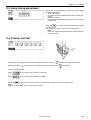
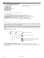
3. Replacing and adjusting the thread take-up lever
q
y
r
e
w
u
t
Fig. A
y
!0
0.5 mm(BES-961BC)
0.7 mm(BES-1261BC)
i
o
u
1. Loosen the set screws w on the right and left of the needle bar case q when viewed from the front, and the set screws e on
both sides of the rear of the needle bar case q.
2. Move the thread take-up shaft r and thread take-up holding shaft t, and remove one or two thread take-up holding(s) u.
• After replacing the thread take-up lever, reverse the above procedure for re-assembly.
[Notes on re-assembly]
• When attaching the thread take-up lever y and the thread take-up holding u, provide a 0.5 mm (BES-961BC) and 0.7 mm
(BES-1261BC) clearance from the end of the thread take-up holding u to both the thread take-up shaft bush i and the thread
take-up holding bush o. The positions of the thread take-up lever y and the thread take-up holding u should be as shown in
figure A; the thread take-up holding u should be inserted into the thread take-up boss !0 without touching the thread take-up
lever y.
BES-961BC.1261BC
19
Chapter 2 Parts Replacement and Adjustment
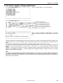
• Turn the pulley and make the following adjustment so that its height is aligned with the other needle thread take-up lever when
the pulley is at 100 degrees (stop position).
!4
!3
Loosen the hole bolt !2 securing the needle thread take-up driven
lever !1 and adjust the position (height) of the needle thread
take-up lever y when the pulley is at 100 degrees (stop position).
Notes:
• Be careful not to make a chattering noise when changing
colors.
• If the needle thread take-up bearing !3 is removed, check
to see that it is securely inserted into the mounting slot of
the head !4 to reinstall it with the hole bolt !5.
!5
!2
!1
20
y
BES-961BC.1261BC
Chapter 2 Parts Replacement and Adjustment
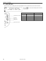
4. Replacing the needle bar
o
y
i
t
Tighten the bolt
y so that
clearance is the
same at all points.
o
t
u
!0
y
This part
should not
make
contact with
anything
nearby.
!0
r
r
e
e
!0
q
w
Remove the set screw q and the needle w.
Remove the needle bar thread guide e from the needle bar r.
Loosen the bolt y of the top dead center stopper t and the screw i of the needle bar clamp u.
Remove the needle bar r by pulling it downward. (The cushion rubber, the top dead center stopper, the needle bar clamp, and
the spring washer will come off.)
• After replacing the needle bar, reverse the above procedure for re-assembly.
1.
2.
3.
4.
[Notes on re-assembly]
• Attach the needle bar thread guide e with its hole facing the front.
• Adjust bottom dead center using the bottom dead center gauge.
• Adjust the top dead center stopper by pressing it against the cushion rubber o at top dead center when the jump bracket and
the needle bar clamp are securely fixed in position (when the " " mark on the pulley is aligned with the one on the belt cover),
and pressing the needle bar clamp downward.
Make sure that the top dead center stopper does not make contact with the needle bar guide rail !0.
• When tightening the bolt y of the top dead center stopper, use the accessory wrench, insert the longer side of the wrench into
the bolt head, and tighten it (Tightening torque: 0.78 N•m).
Notes:
• If the bolt is tightened too much, the needle bar may be sluggish.
• After re-assembly, make sure that the needle bar can be retracted to the top dead center when it is pressed down
and released.
BES-961BC.1261BC
21
Chapter 2 Parts Replacement and Adjustment
5. Replacing the jump bracket
w
r
e
y
q
q
w
t
u
r
y
70°
t
i
1. Loosen the screw q on the left of the head.
2. Remove the base needle bar w by pulling it from above. (The needle bar vertical set e will come off.)
3. Loosen the screw of the jump clamp r, and remove the jump clamp r and the jump bracket y from the base needle bar bush
t. (The jump spring u will come off.)
• After replacing the jump bracket, reverse the above procedure for re-assembly.
[Notes on re-assembly]
• When loosening the screw of the jump clamp r , pay attention to the position of the base needle bar bush t (the spring
strength). Turn the jump bracket y 70 degrees from the natural state (where the flat surface i of the base needle bar bush t
faces the front). Tighten the screw so that the jump bracket y can be moved easily but have no looseness vertically (it can be
moved vertically only 0.03 - 0.05 mm).
• When attaching the base needle bar, align it with the bottom of the head.
22
BES-961BC.1261BC
Chapter 2 Parts Replacement and Adjustment
6. Replacing and adjusting the jump solenoid
q
e
!3
o
i
r
w
u
t
!0
!1
!2
!1
w
y
1. Remove the three bolts, and the jump solenoid w and the jump solenoid base e along with the spring washer from the head q.
2. Loosen the two set screws in the plunger u of the jump solenoid w, and remove the set screw collar r and the solenoid cushion
t.
3. Remove the two nuts, and separate the jump solenoid w from the jump solenoid base e.
4. Remove the connector of the jump solenoid w from the head PCB y.
• After replacing the jump solenoid, reverse the above procedure for re-assembly.
[Notes on re-assembly]
• With the plunger u of the jump solenoid w at the stroke end, adjust the eccentricity of the jump rotary shaft i so that the pipe
!0 attached to the jump solenoid body assembly o is at the front.
• Insert the protrusion of the needle bar clamp !2 into the recess of the jump bracket !1.
Note:
Make sure that the protrusion of the needle bar clamp !2 is completely inserted.
• With the plunger u of the jump solenoid w at the stroke end, make contact with the pipe !0 and the jump bracket !1.
• When the pipe !0 makes contact with the jump bracket !1, tighten the set screws of the set screw collar r to secure the solenoid
cushion t between the jump solenoid w and the set screw collar r.
• Secure the cable of jump solenoid w with fixture !3.
BES-961BC.1261BC
23
Chapter 2 Parts Replacement and Adjustment
7. Replacing the rotary encoder and the sensor PCB
t
q
y
e
w
r
!2
!1
!0
o
!2
o
0.5 mm
t
e
y
i
u
!0
Replacing the rotary encoder
1.
2.
3.
4.
•
•
Remove the screws, and belt covers A q and B w.
Remove the connector r of the rotary encoder e.
Loosen the two set screws of the rotary shaft t attached to the rotary encoder e.
Remove the two screws and the rotary encoder e from the encoder bracket y.
After replacing the rotary encoder, reverse the above procedure for re-assembly.
When reassembling, check that the encoder cable is connected correctly.
[Notes on re-assembly]
• When reattaching the rotary encoder e, tighten the two set screws of the rotary shaft t so that they are aligned with the screw
flats on the driving shaft.
• Provide an approx. 0.5 mm clearance from the end of the encoder bracket y to the end of the driving shaft u, and attach the
encoder bracket y to the encoder adjustment plate i so that they make a right angle.
• Adjust the rotary encoder referring to chapter 3 "13-2. Adjusting the synchronizing signal."
Replacing the sensor PCB
• Remove belt cover B and side cover LB, and separate the connector !0 from the sensor PCB o.
• Remove the two screws, and the sensor PCB o from the needle position sensor set plate !1.
• After replacing the sensor PCB, reverse the above procedure for re-assembly.
[Notes on re-assembly]
• Make sure that the zero bight needle location dog !2 is central to the sensor PCB o.
• Refer to chapter 3 "13-1. Adjusting the machine stop position signal."
24
BES-961BC.1261BC
Chapter 2 Parts Replacement and Adjustment
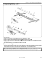
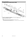
8. Replacing timing belt X
w
q
r
e
∗
w
u
!1
i
!0
!2
t
y
o
1.
2.
3.
4.
5.
Turn off the power.
Remove the screws and the X-feed cover q from the X-cover support plates L and R w.
Loosen the two bolts of X-pulley bracket B e, and the screw r fully.
Remove the four bolts u to separate the X-feed bracket t and the X-belt connection plate y.
Remove the four screws from the X-belt connection plate y. Remove timing belt X i, the belt spacers o, and the timing belt
setting plate !0.
6. Cut timing belt X i to remove it from timing pulleys A !1 and X !2.
• After replacing timing belt X, reverse the above procedure for re-assembly.
[Notes on re-assembly]
• Adjust the belt tension referring to "adjusting the timing belt tension."
* Turn on the power to magnetize the two X-motors on either side. Attach the X-belt connection plate y to the X-feed bracket t
using the four bolts u so that each of the bolts can be centered in the hole. (Do not shift bolts either way.)
• With the power turned off, if the weight of the X-carriage varies when the connectors of the X-pulse motors on both
sides are attached or separate, the X-pulse motors may be out of phase.
Reattach the connectors of the X-pulse motors, turn on the power, and make the above adjustment again.
BES-961BC.1261BC
25
Chapter 2 Parts Replacement and Adjustment
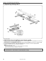
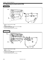
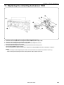
9. Replacing timing belt Y
w
t
q
u
y
e
y
!3
w
r
r
!1
!2
!0
i
o
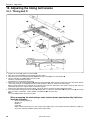
1.
2.
3.
4.
Turn off the power.
Remove the screws and the X-feed cover q from the X-cover support plates L and R w.
Remove the screws of Y-feed cover U e to separate it from the Y-feed cover support plate.
Remove the thirteen screws of the Y-feed frame t. Remove the Y-feed frame t from the Y-carriage y and the rail connecting
plate u, and shift the Y-feed frame t toward the front.
5. From the top of the Y-carriage y, loosen the bolts of the timing belt setting plate o from the holes of the Y-carriage base i.
6. Loosen the two bolts !1 securing the Y-pulley bracket !0 and the bolts securing the Y-feed cover support plate r.
7. Cut timing belt Y !2 to remove it from timing pulleys A !3 and B.
Notes:
When replacing timing belt Y, cut it.
• After replacing timing belt Y, reverse the above procedure for re-assembly.
• Adjust the belt tension before installing the Y-feed frame.
• After replacement, make sure that Y-feed resistance is 147 N with the tubular frame on, and 157 N with the cap
frame attachment on. If the resistance is too great, adjust the Y-carriage.
26
BES-961BC.1261BC
Chapter 2 Parts Replacement and Adjustment
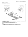
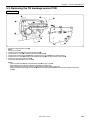
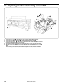
[Notes on re-assembly]
Positioning the Y-feed frame
q
e
e
w
r
r
y
t
i
u
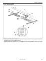
1. Remove table covers L q and R w.
2. From the back of the frame, reinsert post LB e that is the third from the left, and post LB e that is the third from the right, into
the extreme left and right holes on the second steel tube, respectively.
3. Press the Y-feed frame r against posts LB e and secure it using the screws.
4. Return posts LB e to their previous positions.
Note:
In step 3., if the screw holes do not match, loosen the bolts of coupling 15 y connected to the connecting shaft t, move the Y
carriage u or the rail connecting plate i back and forth to adjust the positions of the screw holes.
BES-961BC.1261BC
27
Chapter 2 Parts Replacement and Adjustment
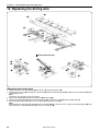
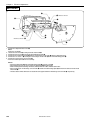
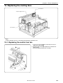
10. Replacing the driving wire
e
q
r
y
w
t
Install the driving wire
!2
o
i
w
t
!0
y
u
!1
r
e i
q
o
tu
y
r
t
[Removing the driving wire]
1. Remove the screws, the X-feed cover q, bed cover C w, and the table cover e.
2. Remove the two screws y securing the Y-feed frame r and the rail connecting plate t, and move the Y-feed frame r all the
way toward the front.
Note:
Perform this step from the rear of the machine.
3. Loosen the four bolts i securing the pulley base u and the bolt o.
4. Remove the driving wire !0 from the rail connecting plate t. Remove the pulley !1 and the driving pulley !2.
5. After replacing the driving wire !0, reverse the above procedure for re-assembly.
Note:
When attaching the rail connecting plate t to the Y-feed frame r using the two screws, make the rail connecting plate t make
contact with the L-shaped portion on the back of the Y-feed frame r.
28
BES-961BC.1261BC
Chapter 2 Parts Replacement and Adjustment
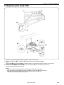
11. Replacing and adjusting the presser lifter parts
11-1. Presser foot
[Replacing the presser foot]
q
1. Select needle bar no.1 q.
2. Remove SEMS w (screw with spring and flat washer), and
the presser foot r from the presser foot shaft e.
• After replacing the presser foot, reverse the above procedure for re-assembly.
• When attaching the presser foot, align its hole with the needle
point. (Loosen SEMS w to adjust the height of the presser
foot r at this time.)
e
w
r
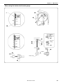
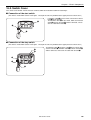
11-2. Presser foot shaft
When the needle bar case is attached
[Replacing the presser foot shaft]
1. Select needle bar no.1.
2. Remove the presser foot from the presser foot shaft.
3. Insert a screwdriver through the hole on the side of the head,
and loosen the screw y of the presser foot shaft clamp t.
4. Remove the screw u, and the needle plate i.
5. Open rotary hook cover B o.
y
t
u
i
e
o
BES-961BC.1261BC
29
Chapter 2 Parts Replacement and Adjustment
6. Remove the three screws !0, and the presser foot guide plate !1.
7. Remove the presser foot shaft e by pulling it downward, and
pass it through the hole of the needle plate bracket.
Note:
The presser foot shaft can also be removed from above if it
can not be removed downward because of being bent.
(When removing the presser foot shaft from above, remove
the needle bar case.)
When removing the presser foot shaft, the spring may pop
out. Be careful.
• After replacing the presser foot shaft, reverse the above procedure for re-assembly.
!0
[Notes on re-assembly]
• The screw of the presser foot shaft clamp t should be kept
loose.
• Before attaching the presser foot shaft e, be sure to insert
the O ring between the presser shaft clamp t and the presser
foot operating base !2.
!1
t
O ring
e
!2
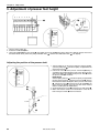
[Adjusting the presser shaft]
1. Turn the pulley until the " " mark on the pulley is aligned
with that on the cover.
2. Move the presser foot shaft e vertically so that the distance
from the end of presser foot shaft bush D !3 to the presser
foot shaft e is 43.9 mm.
!4
t
3. Securely tighten the screw !4 of the presser foot shaft clamp t.
!3
43.9 mm
e
!1
!5
r
30
4. After replacing and adjusting the presser shaft, make sure
that the presser foot r rises and lowers smoothly by moving
it manually using the W retracting lever !5.
Note:
If the presser foot has stopped halfway while rising, the
presser foot guide plate !1 may be attached on an angle.
When tightening the screw of the presser foot shaft clamp,
attach the presser foot to the end of the presser shaft, and
align the hole in the needle plate with the center of the hole in
the presser foot.
BES-961BC.1261BC
Chapter 2 Parts Replacement and Adjustment
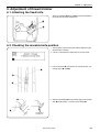
11-3. Replacing and adjusting the W retracting lever and the RET motor lever
[Replacing the W retracting lever]
Remove the nut of the retracting lever shaft w from the presser
foot guide plate q. Remove the W retracting lever e.
• Reverse the above procedure for re-assembly.
q
w
e
[Replacing the RET motor lever]
Loosen the set screw of the RET motor lever r, and remove
it from the pulse motor t.
• Reverse the above procedure for re-assembly.
t
r
[Adjustment]
• Before making this adjustment, turn off the pulse motor t.
• Turn pulley B until " " mark on the pulley is aligned with that
on the cover.
At this time, there should be a 1 - 1.5 mm clearance between
the W retracting lever e and the shaft of the presser foot
shaft clamp y. Loosen the screw u of the RET motor lever
r to adjust it.
u
r
y
1 - 1.5 mm
e
BES-961BC.1261BC
31
Chapter 2 Parts Replacement and Adjustment
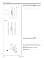
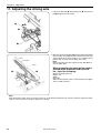
11-4. Replacing and adjusting the pulse motor
q
r
e
y
w
t
1.
2.
3.
4.
5.
Remove the connector e of the pulse motor w from the head PCB q.
Remove the two bolts, and the motor setting plate r from the head.
Loosen the set screw of the RET motor lever t, and remove it from the pulse motor w. (At this time, remove the coil spring y.)
Remove the four bolts of the motor setting plate r. Remove the pulse motor w.
After replacing the pulse motor, reverse the above procedure for re-assembly.
[Adjustment]
Turn pulley B until " " mark on the pulley is aligned with that
on the cover.
At this time, there should be a 1 - 1.5 mm clearance between
the W retracting lever u and the shaft i of the presser foot
shaft clamp. Loosen the set screw o of the RET motor lever
t to adjust it.
o
t
i
1 - 1.5 mm
u
32
BES-961BC.1261BC
Chapter 2 Parts Replacement and Adjustment
12. Replacing and adjusting the gears related to the needle bar flip-up mechanism
BES-961BC
!1
!4
r
u
o
!4
t
t
y
w
!0
e
i
q
!4
Bolt
Bolt
!1
!2
Needle bar
No.3
!3
!4
[Replacing the cam gears]
1. Loosen the screw, and remove the cover q.
2. Loosen the set screws of bevel gear B w, the change cam e, the change box collar r, and the two flange bushes t, and
remove the cam shaft y.
3. Loosen the set screws, and remove bevel gear A u from the shaft of the pulse motor i.
[Assembly and adjustment]
1. Fit bevel gear A u around the shaft of the pulse motor i.
2. When inserting the cam shaft y into the change box o, place the screw flat of the cam shaft y so it is on the side. Pass the two
flange bushes t, the change cam e, bevel gear B w, and the change box collar r through the cam shaft y.
Note:
The change cam e should be attached with its straight portion facing the front (toward the needle bar).
BES-961BC.1261BC
33
Chapter 2 Parts Replacement and Adjustment
3. Secure two flange bushes t between change box collar r and cam shaft u. Check that cam shaft y rotates smoothly without
rattling.
Note:
When attaching the change collar r, either screw hole can be used so long as it is over the screw flat.
4. Insert the positioning bar !2 into the hole of the head !3 through the hole on the front of the needle bar case !1 at the position of
needle bar No. 3 and secure the needle bar case !1. Insert another positioning bar into the adjacent needle bar case and secure
two pieces of the change bracket collar to each head !4 with bolts while checking to see that the needle drops into the hole of the
needle plate attached to the head.
5. Align the position of the change cam e with needle bar No.3, and tighten the set screws of the change cam e.
6. Securely tighten all set screws.
34
BES-961BC.1261BC
Chapter 2 Parts Replacement and Adjustment
BES-1261BC
!0
!2
e
o
u
u
i
t
!3
y
!1
q
w
r
!7
Bolt
Bolt
!4
!5
Needle bar
No.3
!6
!7
[Replacing the cam gears]
1. Loosen the screw, and remove the cover q.
2. Remove the potentiometer w, reduction gear B e, and reduction gear plate B r.
3. Loosen the set screws of bevel gear B t, the change cam y, the two flange bushes u, and reduction gear A i. Remove the
two nuts of reduction gear A i, and then the cam shaft o.
4. Loosen the set screws, and remove bevel gear A !0 from the shaft of the pulse motor !1.
[Assembly and adjustment]
1. Fit bevel gear A !0 around the shaft of the pulse motor !1.
2. When inserting the cam shaft o into the change box !2, place the screw flats of the cam shaft o so they are on the side. Pass
the two flange bushes u, the change cam y, bevel gear B t, and reduction gear A i through the cam shaft o.
Note:
The change cam y should be attached with its straight portion facing the needle bar case.
BES-961BC.1261BC
35
Chapter 2 Parts Replacement and Adjustment
3. Place the two flange bushes u on both sides of the cam shaft o, and tighten the two set screws !3.
4. Adjust the positions of the cam shaft o and reduction gear A i so that they can rotate smoothly without end play.
Note:
When attaching reduction gear A i, either screw hole can be used so long as it is over the screw flat.
5. Secure reduction gear A i using the two nuts.
6. Insert the positioning bar !5 into the hole of the head !6 through the hole on the front of the needle bar case !4 at the position of
needle bar No. 3 and secure the needle bar case !4. Insert another positioning bar into the adjacent needle bar case and secure
two pieces of the change bracket collar to each head !7 while checking to see that the needle drops into the hole of the needle
plate attached to the head.
7. Align the position of the change cam y with needle bar No.3, and tighten the set screws of the change cam y.
8. Securely tighten all set screws.
36
BES-961BC.1261BC
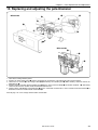
Chapter 2 Parts Replacement and Adjustment
13. Replacing and adjusting the potentiometer
u
BES-961BC
r
y
o
t
q
!0
i
w
BES-1261BC
r
e
t
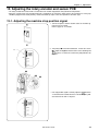
1. Turn off the sewing machine power.
2. Remove the color change cover q which is attached to the change box at the front-right of the sewing machine.
3. Loosen the set screws r of the change collar w (BES-961BC) or reduction gear e (BES-1261BC), and then remove the
potentiometer t.
4. Remove the bolts, and then open the bridge cover i which is at the rear of the bridge u on machine head No. 1 y, while being
careful not to touch the machine head circuit board and harnesses.
5. Gently pull the cable !0 of the potentiometer t which is connected to connector P7 of the machine head circuit board o to
disconnect it from the machine head circuit board o.
Refer to page 176 “18-4. Change Color Section” to lead cable.
BES-961BC.1261BC
37
Chapter 2 Parts Replacement and Adjustment
BES-961BC
u
o
!1
!2
!6
!3
i
!4
!5
6. Pass the cable !2 for the new potentiometer !1 into the bridge u from the change box side, and connect it to connector P7 of the
machine head circuit board o.
7. Install the bridge cover i to the bridge u, while being careful not to touch the machine head circuit board and harnesses.
8. Without the potentiometer !1 installed to the change box !3, press and hold the ( ) jog key on the operation panel and turn on
the power.
9. Turn the knob !4 at the bottom of the change box !3 counterclockwise (when looking from above) as far as it will go, and then
turn it about 1/3 of a turn back clockwise so that the set screw !6 on the change cam !5 is facing directly upward.
Note:
Needle bar No. 1 will be at the sewing position at this time.
38
BES-961BC.1261BC
Chapter 2 Parts Replacement and Adjustment
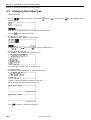
10.Turn on the power of the machine.
11.The machine starts the needle bar moving test in the test
mode. Refer to "Test Mode" in chapter 4.
!1
12.Turn the potentiometer !1 all the way to the left as shown in
the illustration to the left. When it is then turned gently to the
right, the buzzer on the operation panel sounds.
• The point where the buzzer sounds is the potentiometer !1
position for the first stitch. The operation panel will be displayed as shown in the illustration to the left at this time.
13.Install the potentiometer to the change box while the buzzer
is sounding.
Notes:
• Install the potentiometer !1 while the buzzer is sounding
so that it does not move out of its adjusted position.
• Install the potentiometer while paying attention not to move
the needle position adjusted in step 9.
!1
q
14.Once the potentiometer has been installed, press the key to
move the needle bar case on the operation panel to needles
1 to 9 (BES-961BC) or needles 1 to 12 (BES-1261BC) in
order to check operation.
15.After checking the operation, install the color change cover
q.
BES-961BC.1261BC
39
Chapter 2 Parts Replacement and Adjustment
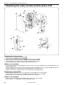
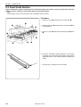
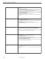
14. Replacing and adjusting the movable and fixed knives
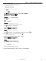
• After replacing the movable and fixed knives, attach them as
follows:
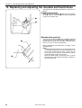
[Fixed knife position]
When attaching the fixed knife q, while pressing it against
the pin w, move the fixed knife q all the way backward until
it stops at the end of its slot.
q
w
[Movable knife position]
The tip of the movable knife e always should be positioned
so that it projects 1 mm from the fixed knife r. Adjust the
position of the movable knife using the connecting rod so
that it is the same as after thread trimming.
r
• Refer to "Adjustment of thread trimmer " in chapter 3, Standard Adjustment.
Notes:
• If a thread trimming error occurs, the pressure be-tween
the movable and fixed knives may be inappropriate even
if they make contact with each other. In this case, put
one or two spacers between the movable knife and the
needle plate base to adjust the pressure.
• When the movable knife is retracted too much, it can not
go between the upper and lower threads, resulting in a
thread trimming error.
e
1 mm
40
BES-961BC.1261BC
Chapter 2 Parts Replacement and Adjustment
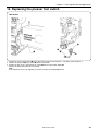
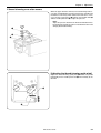
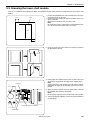
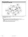
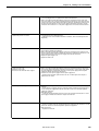
15. Replacing and adjusting the lower shaft module
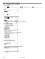
Note: Be sure to turn off the power before proceeding with that below.
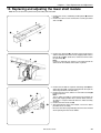
1. Remove the screws, embroidery needle plate B q and bed
cover w.
2. Remove the three screws and washers securing the lower
shaft case e.
w
q
e
3. Remove the connector r of the lower shaft sensor harness
and the connector of the lower shaft stepping motor harness
from the BC PCB t. (At this time, remove the harness from
the cord clamp y.)
Note:
Remove a connector if its harness is not connected to the
connector on the PCB but connected in a cylinder.
y
r
t
y
i
u
o
The wind
4. Remove the two bolts to separate connecting rod B u from
connecting rod C i. (Leave the protrusion on the tip of the
connecting rod off the movable knife.)
5. Remove the two screws, and the DC fan motor assembly o
by lifting it upward.
Note:
The DC motor assembly is removed just for removing the
lower shaft stepping motor harness and the lower shaft sensor harness. Keep the connector of the DC motor assembly
attached.
6. Remove the lower shaft case e.
7. After replacing the lower shaft module, reverse the above
procedure for re-assembly.
• Be sure to refer to the page indicating the items to be checked
when replacing the lower shaft module.
e
BES-961BC.1261BC
41
Chapter 2 Parts Replacement and Adjustment
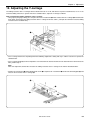
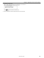
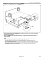
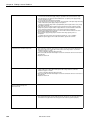
[Adjustment]
Checking the needle penetration location
• Right and left adjustment
Loosen the three bolts q for a fixed bed or seven bolts e
securing bed support A w for a retracting bed. Move the bed
in the direction of the arrow to adjust it.
• Position the needle bar case using the positioning bar, then
set the needle at its lowest position to adjust it so that it is at
the center of the outer rotary hook.
q
e
w
• Back and forth adjustment
Loosen the three screws t, and move the lower shaft case
r back and forth to adjust it.
Notes:
• When checking the needle penetration point at the lower
shaft module, be sure to adjust the thread trimming.
• As to the clearance or meeting point between the needle
and rotary hook, refer to chapter 3.
r
42
t
BES-961BC.1261BC
Chapter 2 Parts Replacement and Adjustment
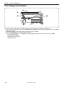
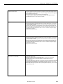
Items to be checked when replacing the lower shaft module
• When attaching the lower shaft module, make sure that the two harnesses of the lower shaft module are not caught between the
lower shaft fan and the bed.
• When fixing the harnesses of the lower shaft module to the bed using the cord holder, be sure to attach them at the same
position as they were before they were removed.
• When the bed and the lower shaft module are viewed from the front, make sure that the lower shaft module is securely attached
to the bed without any inclination, and then adjust the needle penetration position.
Bed
There should be no gap around these portions.
• When adjusting the needle penetration position, place the needle plate on the lower shaft module, turn the pulley 140 degrees,
and tighten the screws and the bolts to fix the lower shaft module at the position where the needle is centered in the hole in the
needle plate in the back and forth directions.
Then, move the needle plate so that the needle is centered in the hole of the needle plate in the right and left directions. Make
sure that the needle plate is parallel to the needle plate base.
[Adjustment]
Loosen the four screws of the needle plate base, move the needle plate base with the needle plate temporarily attached, to the left
and right to adjust the needle to the center of the hole in the needle plate.
Notes:
• After moving the needle plate base, be sure to adjust the thread trimmer.
• When adjusting the needle penetration position, first adjust it for needle bar No.5, and then check the remaining needle bars
for their needle penetration positions.
• When attaching the harnesses of the lower shaft module to the BC PCB, do not mistakenly attach the wrong connectors.
Connector color (on BC PCB)
Fixed bed
White (for cooling fan)
Red
Retracting bed
Blue (for cooling fan)
Blue
• Be sure to again adjust the needle bar height, timing position, the clearance between the needle and the rotary hook point,
and the thread trimmer.
• Perform "8. BC Auto Test" (select on the BC test menu) as a final check. Refer to page 94, “3-14. Lower shaft module test.”
• After adjustment, perform sewing and carefully check the lower shaft module at the highest speed. If there is an abnormal
sound coming from the lower shaft module, again replace it with a new one.
BES-961BC.1261BC
43
Chapter 2 Parts Replacement and Adjustment
1mm±0.2
Coupling hub F
44
Coupling hub R
[Adjusting the lower shaft sensor]
1. Remove the cover from the detached lower shaft module.
Photo sensor
Slit plate
2. Check the position of the slit plate of the coupling hub (set)
as follows:
• Check to see if the photo sensor does not make contact with
the slit plate.
• Check to see if the clearance between the photo sensor and
the coupling hub R is proper.
3. Check the sensor after making the above checks. Replace
the sensor PCB if the measured result is not acceptable.
BES-961BC.1261BC
Chapter 2 Parts Replacement and Adjustment
16. Replacing the presser foot switch
BES-961BC
w
r
q
1.
2.
3.
•
e
Remove the screw, and the cover q on the right of the head you want to replace. (The figure shows head no. 1.)
Remove the connector e of the switch w from the head PCB.
Remove the two screws, and separate the switch w from the micro switch holder r.
Reverse the above procedure for re-assembly.
Note:
As to adjustment, refer to "9. Adjusting the switch" in chapter 3 Standard Adjustment.
BES-961BC.1261BC
45
Chapter 2 Parts Replacement and Adjustment
17. Replacing and adjusting the solenoid that controls pulley
1. Remove the screws, and motor covers L q and F w.
q
w
2. Separate the connector of the solenoid from that of power
supply PCB B e. Remove the connector from 20B on the
rear of the control box r.
r
3. Remove the two nuts t and the solenoid.
4. After replacing the solenoid, reverse the above procedure
for re-assembly.
t
e
5. With the solenoid turned off (when it has completely retracted),
there should be a 2 mm clearance between the tip of the
solenoid and the pulley stop lever y. Loosen the two bolts
u of the solenoid bracket i to adjust it in the direction of the
arrow.
2 mm
u
i
y
2 mm
46
BES-961BC.1261BC
Chapter 3 Adjustment
Chapter 3 Adjustment
CAUTION
Turn off the power switch and pull out the plug
before starting adjustment. Failure to do so may
start the machine unintentionally through an
accidental activation of the START switch, resulting in bodily injuries.
• Adjustment
If adjustment should be made while the power
switch is turned on, pay special attention to your
safety.
Maintenance and inspection of the machine
should be conducted only by trained engineers.
1. Adjusting needle bar height
180°
q
w
q
y
t
u
e
r
Tighten the
bolt u so that
these
clearance can
be even.
i
Do not hit
this
section.
i
10.8mm
BES-961BC.1261BC
47
Chapter 3 Adjustment
1. Dismount the pulley cover and turn the pulley B q until the pulley scale indicates 180˚ and the needle bar is set at the lowest
position. (The pulley " " mark and the stop mark " " are aligned.)
2. Insert the positioning bar w into the hole of the pulley B q and fix the drive shaft.
Note:
Turn the pulley B q securely in the clockwise direction to eliminate a backlash.
3. Loosen the needle bar clamp set screw e and the bolt u of the top dead center stopper t when the needle tip is positioned
10.8 mm above the center of the rotary hook shaft. Adjust the position of the needle bar thread guide so that the set screw r
on it is turned to the right by 25 ~ 30˚. Tighten the needle bar clamp set screw e securely.
Note:
When tightening the needle bar clamp set screw e, the hole in the needle bar guide should face the front.
4. After adjustment is finished, remove the positioning bar w.
5. Set the needle bar at the highest position (where the pulley B q indication mark " " and the cover indication mark " " are
aligned). Lightly press the top dead center stopper t toward the cushion rubber y, and tighten the top dead center stopper bolt
u while pressing down the needle bar clamp so that it faces the front.
Notes:
• Make sure that the top dead center stopper does not hit the needle bar guide rail i at this time.
• When tightening the bolt u of the top dead center stopper, use the accessory wrench, insert the longer side of the wrench
into the bolt head, and tighten it. (Tightening torque: 0.78N.m)
(If the bolt is tightened too much, the needle bar may be sluggish.)
• After adjustment, make sure that the needle bar can return to top dead center when it is pressed down 10 mm and then
released.
• The (rotation) direction of the needle bar may be changed after its height is adjusted. Make sure that the long groove of the
needle faces the front.
48
BES-961BC.1261BC
Chapter 3 Adjustment
When using the bottom dead center gauge
q
180°
w
q
Tighten the
bolt o so that
these
clearance can
be even.
i
u
t
!0
Do not hit
this
section.
o
y
!0
e
10.8mm
Cutting
section
e
Cutting section
r
BES-961BC.1261BC
49
Chapter 3 Adjustment
1. Turn the pulley B q until the scale of pulley B q indicates 180˚ (where the pulley B q indication mark " " and the stop mark " "
are aligned) and the needle bar is set at the lowest position.
2. Insert the positioning bar w into the hole of the pulley B q and fix the drive shaft.
Note:
Turn the pulley B q securely in the clockwise direction.
3. Insert the bottom dead center gauge e into the rotary hook r.
4. Loosen the screw y and bolt o of the needle bar clamp t and move the needle bar up and down until the needle tip touches
the gauge e lightly.
Notes:
• The needle point should touch the gauge at a place other than the cutting section.
• The bottom dead center gauge should be set in or removed from the rotary hook with its cutting section facing upward.
5. Tighten the screw y of the needle bar clamp t securely.
6. After adjustment is finished, remove the positioning bar w.
7. Set the needle bar at the highest position (where the pulley B q indication mark " " and the cover indication mark " " are
aligned). Lightly press the top dead center stopper u toward the cushion rubber i, and tighten the top dead center stopper bolt
o while pressing down the needle bar clamp so that it faces the front.
Notes:
• Make sure that the top dead center stopper u does not hit the needle bar guide rail !0 at this time.
• When tightening the bolt 6 of the top dead center stopper, use the accessory wrench, insert the longer side of the wrench into
the bolt head, and tighten it. (Tightening torque: 0.78N.m)
(If the bolt is tightened too much, the needle bar may be sluggish.)
• After adjustment, make sure that the needle bar can return to top dead center when it is pressed down 10 mm and then
released.
• The (rotation) direction of the needle bar may be changed after its height is adjusted. Make sure that the long groove of the
needle faces the front.
50
BES-961BC.1261BC
Chapter 3 Adjustment
2. Adjustment of clearance between needle and rotary hook
1. Turn the power switch off.
2. Select the needle bar No. 1 q.
q
w
3. Remove two flat screws w and dismount the needle plate e.
e
4. Align the pulley indication mark " " and the stop mark "NH "
by turning the pulley.
2mm
r
2mm
5. Turn the rotary hook r manually so that the point comes
upward.
6. Loosen the set screw y on the side of the bed t.
u
7. Turn the eccentric screw u on the left side of the bed t
using a regular screwdriver and adjust a clearance between
the needle and the rotary shaft to 0.2 - 0.4 mm.
y
t
0.2 - 0.4mm
8. Adjust the clearance between the needle and the rotary hook's
point to 0.2 - 0.4 mm at the needle bar No. 9 (No. 12 needle
for BES-1261BC).
Notes:
• If the clearance between the needle and the rotary hook
point is not within 0.2 - 0.4 mm, again perform from step 4
as described above, and set the smaller clearance between either needle bar No.1 or 9 (No.1 or 12 for BES1261BC) and the rotary hook point to approx. 0.2 mm.
• If the clearance between the needle and the rotary hook
point is 0.5 mm or more, replace the needle and the needle
bar with new ones.
• If the clearance is too small when a thicker material is
sewn, the needle may be bent or broken.
BES-961BC.1261BC
51
Chapter 3 Adjustment
3. Adjustment of timing between needle and rotary hook
1. Turn on the power of the machine.
2. The machine starts the rotary hook timing adjustment in the
test mode. Refer to "Test Mode" in chapter 4.
The rotary hook of each head turns to the currently set timing
position so that the rotary hook can be adjusted.
140°
3. Manually turn pulley B until the relationship between the
needle point and the rotary hook's point q can be easily
checked (at around 140 degrees of the scale).
150
200
q
4. Press the STEP FWD/ BACK switch to move the rotary head
of each head to adjust it.
• STEP FWD
For rotating the rotary hook little by little in the clockwise direction
• STEP BACK
For rotating the rotary hook little by little in the counterclockwise direction
Make this adjustment for each head so that the needle and
the rotary hook's point can fit with each other.
100°
52
5. After adjustment is finished for each head, set pulley B to the
stop position (at 100 degrees of the scale) and press the
ESC
key three times to return to the embroidery initial screen.
The aligned position adjusted according to the above procedure is stored and the rotary hook returns to the stop position.
BES-961BC.1261BC
Chapter 3 Adjustment
4. Adjusting the clearance between the rotary hook and the inner rotary
q
1-1.5mm
w
e
1. The clearance between the rotary hook q and the inner rotary hook stopper w should be enough to pass the thread
through the clearance easily.
2. Loosen the two screws e to adjust the clearance between
the rotary hook and the inner rotary hook stopper to 1-1.5mm.
3. Lower the needle. Make sure that the inner rotary hook stopper w is inserted into the center of the groove of the rotary
hook q.
Notes:
• If the inner rotary hook stopper does not come to the center of the needle, the needle or the needle bar may be
bent. If both are not bent, replace the inner rotary stopper
with a new one.
• If there is no problem with the needle or the needle bar,
set the needle to its bottom dead center to check if the
needle comes to the center of the shaft of the outer rotary
hook.
If it does, move the needle plate base to the left and right
to center the needle.
(At this time, re-adjust the thread trimmer.)
If it does not, adjust the needle penetration position.
• If the two clamping bolts securing the inner rotary hook
stopper are loosened, the thread trimming guide plate
moves along with it. Therefore, be sure to reinstall the
thread trimming guide plate properly after adjusting the
inner rotary hook stopper.
(Pull the plate to the forefront and secure it.)
BES-961BC.1261BC
53
Chapter 3 Adjustment
5. Adjustment of presser foot height
e
q
w
Material
1. Turn the power switch off.
2. Select the needle bar q No.1.
3. Loosen the SEMS e of the presser foot w, and adjust the presser foot w until it comes above the cloth top surface when it is at
the bottom dead center (where the pulley indication mark " " and the cover indication mark " " are aligned).
Adjusting the position of the presser shaft
1. Turn the pulley to set the presser foot to its lowest position.
(Turn the pulley until mark on the pulley is aligned with the
one on the belt cover.)
2. Loosen the screw w of the presser shaft clamp q using a
screwdriver inserted through the hole in the side of the machine head. Adjust the position of the presser shaft e so that
the presser shaft e is 43.9mm.
[Adjustment]
Turn the pulley until the mark on the pulley is aligned with
the one on the belt cover. Attach the presser foot r, which is
lowered to the bottom dead point, to the presser shaft clamp
q. Loosen the screw w of the presser shaft clamp q at the
place where the bottom of the presser foot makes contact
with the needle plate (for holder base).
3. Securely tighten the screw w of the presser shaft clamp q.
4. Make sure that the needle is inserted into the center of the
hole in the presser foot r when it is lowerd.
w
q
e
43.9mm
r
54
BES-961BC.1261BC
Chapter 3 Adjustment
6. Adjustment of thread trimmer
6-1. Attaching the fixed knife
Attach the fixed knife q to the pin w and move it backward to
the end of the slot, then mount it there.
q
w
6-2. Checking the movable knife position
1. Turn the power switch on and wait until the hoop home position detection is finished.
2. Carry out "Thread trimmer adjustment" in the test mode.
3. Loosen two bolts e that connect the thread trimmer connecting rods C q and B w.
q
e
w
t
r
4. Tighten the two bolts e until the triangle part of the movable
knife r is projected by 1 mm from the fixed knife t.
1mm
Triangle part of
movable knife
BES-961BC.1261BC
55
Chapter 3 Adjustment
* Precautions for tightening the two bolts e:
q
• The thread trimmer connecting rod B w has a backlash of
about 0.1 - 0.2 mm back and forth. Tighten the two bolts e
while pulling them forward by the backlash amount.
• Tighten the two bolts e so that the thread trimmer connecting rods B w and C q are positioned in a straight line.
e
w
* Bad example
5. After adjustment is finished, press the
return to the embroidery initial screen.
t
ESC
key four times to
6. Turn the power switch off once, then on again. Check that
the clearance between the movable knife r and the fixed
knife t is 1 mm.
7. When adjusting again, follow the step 2 and after.
Note:
When the movable knife is retracted too much, a thread trimming error may occur.
r
1mm
56
BES-961BC.1261BC
Chapter 3 Adjustment
If thread trimming error often occurs
When the upper thread is trimmed, a thread trimming error occurs due to inappropriate pressure between the movable and
fixed knives even if they make contact with each other. In this
case, put one or two spacers e between the movable knife q
and the needle plate base w to adjust the pressure.
Note:
Adjust the pressure between the fixed and movable knives
by putting two threads of rayon 2/120d between them and
carrying out thread trimming.
q
e
w
[Adjusting the thread trimming guide plate]
Adjust the thread trimming guide plate r so that it is placed
horizontally on the needle plate base t and vertically to the
forefront.
t
r
BES-961BC.1261BC
57
Chapter 3 Adjustment
7. Adjusting the thread wiper
q
e
!0
r
u
y
u
i
Align
t
w
BES-961BC
o
i
Needle
y
1. Move solenoid arm q in the direction of the arrow with your finger. Loosen three bolts e and adjust thread hook w for smooth
movements.
2. If there is a difference in motion between needle bars No. 1 and No. 9 (No. 12 for BES-1261BC), loosen four screws r and
make an adjustment by moving thread presser base t in the direction of the arrow.
Make sure that no interference will occur when pressure foot y is raised by the solenoid.
3. Move finger guard plate u up and down, and align the top of finger guard i with the tips of the needles.
4. After the above steps are complete, check thread hook w for smooth movements.
If the thread hook does not move smoothly, apply grease (Grease Tank BR2 (black)) to the gray part of thread guide solenoid
base !0 and check its movements.
Notes:
• Care should be taken if the finger guard is inclined. If the finger guard in such a state is pushed excessively toward the
needle at the time of color change, it may interfere with the presser foot.
• Then make an adjustment in the crosswise direction by sliding bolt o of finger guard i.
58
BES-961BC.1261BC
Chapter 3 Adjustment
8. Adjusting the jump solenoid
e
!1
r
t
u
q
Contact
w
Fig A
q
y
!0
i
o
1. Check to see that the projection of the needle bar connecting bracket w completely fits into the recess of the jump bracket q.
(Refer to figure A.)
2. Make the jump rotary pipe r of the jump rotary body assy e make contact with the jump bracket q. Make the plunger u of the
jump solenoid y make contact with the jump rotary body shaft t, which is opposite the jump rotary body e. Place the solenoid
cushion o between the jump solenoid y and the set collar i, and tighten the set screw !0.
3. Adjust the jump guide shaft !1 and the set collar i so that the needle bar clamp w can be taken off the jump bracket q when the
plunger u of the jump solenoid y is at the stroke end.
Note:
After adjustment, make sure that, at low speed, the jump solenoid always jumps and returns to its original position.
BES-961BC.1261BC
59
Chapter 3 Adjustment
9. Adjusting the switch
BES-961BC
w
( q)
No.6
e
1. Select needle bar no.6, and turn off the power.
2. Remove screws, the UR cover q, the UR switch cover w, and the cover e.
Note:
When removing the UR switch cover, remove the emergency stop switch connector.
3. Turn the change pulley r to set needle bar no. 1.
r
4. Attach the emergency stop switch connector of the UR switch
cover w. The UR switch cover w will hang down.
w
60
BES-961BC.1261BC
Chapter 3 Adjustment
BES-1261BC
w
(q)
No.6
e
1. Select needle bar no.6, and turn off the power.
2. Remove screws, the UR cover q, the UR switch cover w, and the cover e.
Note:
When removing the UR switch cover, remove the emergency stop switch connector.
3. Turn the change pulley r to set needle bar no. 1.
r
4. Attach the emergency stop switch connector of the UR switch
cover w. The UR switch cover w will hang down.
w
BES-961BC.1261BC
61
Chapter 3 Adjustment
5. While pressing the jog switch
on the standalone panel, turn on the power.
The following screen is displayed when you subsequently press the
key.
Input "961" as the password when the above screen is displayed and press the
displayed.
6. Select presser foot
from
key. The menu screen for adjustment is
. The presser foot will lower.
7. Match the slot of the W motor sensor plate t and ø 3 mm
diameter hole in the head y, and insert the gauge pin u to
secure the W motor sensor plate t.
t
y
u
62
BES-961BC.1261BC
Chapter 3 Adjustment
8. Loosen the two perforated bolts o, and vertically move the
micro switch holder i, which is on the lower right of the head,
until the switch !0 is turned on, and then secure the micro
switch holder i.
• When the switch !0 is on, the buzzer sounds and the MENDING lamp (green) on the head is lit.
Note:
Secure the micro switch holder i in the position just after the
switch !0 is on.
If it is secured at a higher position at that time, the presser
foot may retract at a lower position.
9. Remove the gauge pin u , and adjust the switch on each
head in order.
i
o
!0
u
10.After all heads are adjusted, make sure the presser foot rises and lowers normally by pressing the jog keys ( ) and ( ) on the
panel.
• In particular, make sure the presser foot does not make contact with the thread clamp when the presser foot is rising.
11.Press the
ESC
key three times to return to the password input screen and turn off the power.
12.Turn the change pulley r to select needle bar no. 6, and reattach the covers.
13.Turn on the power. Make sure that the presser foot rises and the carriage moves to the home position.
BES-961BC.1261BC
63
Chapter 3 Adjustment
10. Adjusting the timing belt tension
10-1. Timing belt X
w
i
q
e
y
r
y
u
t
(A)
14.7N
320
10mm
320
Remove the screws w, and the X-feed cover q.
Move the X-feed frame e all the way towards the pulse motor.
Loosen the two screws of X-pulley bracket B r and the four screws y of the X-feed bracket t.
Turn the adjusting screw u to adjust the belt tension.
Clockwise: Tension will be increased.
Anti-clockwise: Tension will be decreased.
5. Tighten the screws of X-pulley bracket B r and the X-feed bracket t. Adjust the belt tension so that the slack will be approx.
10 mm with a load of 14.7 N applied to the place indicated by the arrows as shown in the above figure.
With the power turned off, if the weight of the X-carriage varies when the connectors of the X-pulse motors on both sides are
attached or separate, the X-pulse motors may be out of phase.
Reattach the connectors of the X-pulse motors, turn on the power, and make the above adjustment again.
6. Turn on the power to magnetize the X motors i on both sides. Secure the X-feed bracket t using the screws y so that they
are in the center of each hole. Secure another X-feed bracket t in the same way.
Note:
The screws y should be central in every hole.
1.
2.
3.
4.
When measuring the slack using a sonic tension meter manufactured by Unitta Inc.,
input the following:
When measuring at point (A)
Weight: 4.0
Width: 20
Span: 806
Adjust the belt tension so that a sonic tension meter applies 206 N ± 9.8 N to the belt when it bounces at point (A).
At this time, nothing should be making contact with the belt.
64
BES-961BC.1261BC
Chapter 3 Adjustment
10-2. Timing belt Y
r
w
e
q
y
t
o
t
u
i
1. Remove the screws w and the X-feed cover q.
2. Remove the 13 screws r from the Y-feed frame e. Remove the Y-feed frame e from the Y-carriage t and the rail connecting
plate y, and shift the Y-feed frame e toward the front.
3. Viewed from the top of the Y-carriage t, loosen the 16 bolts o of the timing belt setting platei from the holes of the Y-carriage
u. (Do not remove them.)
BES-961BC.1261BC
65
Chapter 3 Adjustment
4. Loosen the eight bolts !1 securing the Y-pulley bracket !0.
5. Turn the tension adjusting bolts !3 of the Y-feed cover support plate !2 to adjust the belt tension.
Clockwise: Tension will be increased.
Anti-clockwise: Tension will be decreased.
!0
!2
!3
!1
14.7N
7mm
!5
o
Part (A)
t
!4
265mm
!1
The front of the machine
!0
i
6. Move the Y-carriage t all the way backward (from the front of the machine) until it makes contact with stopper R !4.
7. Tighten the screws o of the timing belt setting plate i which is on either timing belt Y to be measured. Apply a load of 14.7 N
to the position 265 mm away from the pulley !5 at the front, and adjust the belt tension so that the slack will be approx. 7 mm.
Note:
Do not adjust the belt tension when the timing belt setting plates on both sides are secured.
When measuring the slack using a sonic tension meter manufactured by Unitta Inc.,
input the following:
When measuring at point (A)
Weight: 4.0
Width: 20
Span: 640
Adjust the belt tension so that a sonic tension meter applies 206 N ± 9.8 N.
Note:
Before measuring the slack of the belt, tighten the eight bolts !1 securing the Y-pulley bracket !0.
8. After adjusting the tension of the four belts, tighten the bolts o of the timing belt setting plate i.
Note:
After replacement, make sure that Y-feed resistance is 147 N with the tubular frame on, and 157 N with the cap frame attachment on. If the resistance is too great, adjust the Y-carriage.
66
BES-961BC.1261BC
Chapter 3 Adjustment
y
q
w
r
e
y
t
t
i
u
!0
t
o
Positioning Y-feed frame (Perform from the rear of the machine.)
1. Remove the screws, and table covers L q and R w.
2. From the back of the frame, reinsert post LB e that is the third from the left, and post LB r that is the third from the right, into
the extreme left and right holes on the second steel tube, respectively.
3. Press the Y-feed frame t against posts LB e and r and secure it using the 13 screws y.
4. Return posts LB e and r to their previous positions.
Note:
When the Y-feed frame t is secured and the screw holes do not match, loosen the bolts of coupling 15 i connected to the
connecting shaft u, and move the Y-carriage o or the rail connecting plate !0 back and forth to adjust the positions of the screw
holes.
BES-961BC.1261BC
67
Chapter 3 Adjustment
11. Adjusting the driving wire
1. Loosen the four bolts w of the pulley base q, and turn the
bolt e to adjust the wire tension.
e
w
q
240mm
14.7N (8mm)
Part (A)
w
r
2. Move the rail connecting plate r all the way backward (viewed
from the front), and adjust the wire tension so that the slack
will be approx. 8 mm with a load of 14.7 N applied to the
position 240 mm away from the pulley at the front.
Note:
Before measuring the slack, tighten the four bolts w to secure the pulley base.
When measuring the slack using a sonic
tension meter manufactured by Unitta
Inc., input the following:
When measuring at point (A)
Weight: 19.1
Width: 1
Span: 480
Adjust the belt tension so that a sonic tension meter applies
206 N ± 9.8 N to the belt.
Note:
After replacement, make sure that Y-feed resistance is 147 N with the tubular frame on, and 157 N with the cap frame attachment on. If the resistance is too great, adjust the Y-carriage.
68
BES-961BC.1261BC
Chapter 3 Adjustment
12. Adjusting the Y-carriage
The sliding resistance of the Y-carriage with the tubular frame on is 147 N, and with the cap frame attachment on, 157 N. If the
measured sliding resistance is greater than these standard values, adjust the Y-carriage as follows:
How to measure the sliding resistance of the Y carriage
• Using a push-pull gauge, slowly press the place where the Y-feed frame q makes contact with the Y carriage w in the direction
of the arrow, and measure the sliding resistance of the Y-carriage for all of its stroke. (Compare the maximum measured sliding
resistance to the standard value.)
q
w
• If the Y-carriage movement is impeded, perform the following adjustments starting with step 1 until the resistance is equal to the
standard value.
• If the Y-carriage gradually becomes impeded as it is moved from the back to the front or in the latter half of the movement to the
front, perform step 4.
Note:
After each adjustment, do not fail to measure the sliding resistance of the Y-carriage in the manner described above.
• Remove the X-feed cover e and the button head screws t to separate the Y-feed frame q and the rail connecting plate r, and
measure the resistance of the Y-carriage w.
t
e
r
q
w
BES-961BC.1261BC
69
Chapter 3 Adjustment
12-1. When the sliding resistance of the Y-carriage is below the
standard value
Check the clearance between the Y-feed frame q and the rail connecting plate w.
When there is no clearance
Move the Y-feed frame q as close as possible to the needle plate side when viewed from the rear of the machine, and tighten the
button head screws e.
Note:
When a button head screw can not be inserted into a hole in the rail connecting plate w, move the Y-feed frame e, temporarily
insert another button head screw into the hole, and securely tighten the button head screw which is on the needle plate side.
When there is clearance
Insert the washer r between the Y-feed frame q and the rail connecting plate w, and tighten the button head screws e and the
spring washers t.
q
t
e
r
w
• After adjustment, measure the sliding resistance of the Y-carriage again. If the measured resistance is still not equal to the
standard value, perform step 12-2.
70
BES-961BC.1261BC
Chapter 3 Adjustment
12-2. When the sliding resistance of the Y-carriage is over the standard value even after adjustment 12-1
• Loosen the bolts w on both sides of the Y-carriage q, raise
the Y-carriage q to adjust the clearance between the Y carriage q and the Y-feed frame, and retighten the bolts w.
q
• Loosen the bolts t to separate the rail connecting plate e
and the linear guide r, raise the rail connecting plate e so
as not to leave a gap between the felt u on the back of the Yfeed frame y and the bed cover i, and then retighten the
bolts t.
Note:
When the position of the rail connecting plate e is changed
as described above, the clearance between the tubular frame
and the needle plate may become greater, resulting in the
needle plate rattling during sewing.
Do not raise the front (the needle plate side) of the rail connecting plate e too much.
w
y
u
i
t
e
r
• After this adjustment, measure the sliding resistance of the Y-carriage again. If it is still over the standard value, make adjustment written in 12-3.
BES-961BC.1261BC
71
Chapter 3 Adjustment
12-3. When the sliding resistance of the Y-carriage is over the standard value
Remove both Y-feed covers U q, measure the sliding resistance of the Y-carriage again. If the sliding resistance becomes less,
check the following items:
• Check if Y-feed covers U q that hold spacer felt w down are
deformed. If they are, straighten them.
• When the sliding resistance becomes great before and after
the Y-carriage, reattach the Y-feed cover support plates e
and r as high as possible.
q
e
w
r
q
Notes:
• If Y-feed cover U is raised too much, it may creak during
sewing. Do not change its position more than necessary.
(To prevent vibration, have the Y-feed cover U just make
contact with the Y-carriage.)
• Finish adjustments 1 to 3 when the sliding resistance is
equal to the standard value.
There is no need to perform all adjustments.
w
12-4. When linear guide 505L, which is attached to machine head
No.3, is not parallel to the top surface of the bed
• Loosen the bolts of linear guide 505L q, move the Y-feed
frame to adjust the height of linear guide 505L q at both
ends of the stroke. (The felts should just touch the top surface of the bed.)
q
72
BES-961BC.1261BC
Chapter 3 Adjustment
13. Adjusting the rotary encoder and sensor PCB
• The rotary encoder and sensor PCB is used to detect the needle stop position and synchronize hoop motion.
• When the machine stops after thread trimming or is stopped for an emergency during sewing, the needle bar is in the jump
condition (stopped in the raised position), and its thread take-up stops at the same position as the other eight.
13-1. Adjusting the machine stop position signal
1. Turn on the power, and the machine starts the encoder signal test in the test mode.
Refer to page 79, "Test mode".
2. Turn pulley B q in the normal direction. Loosen the screws
w to adjust the dog e so that the buzzer starts sounding and
90˚
becomes "H" when the scale on the pulley indicates 90
degrees.
q
w
e
* If the stop position signal is correctly adjusted,
becomes
"H" and the buzzer sounds when the scale on the pulley indicates between 90 and 110 degrees.
BES-961BC.1261BC
73
Chapter 3 Adjustment
13-2. Adjusting the synchronizing signal
1. Turn on the power, and the machine starts the encoder signal test in the test mode.
Refer to page 79, "Test mode".
2. Loosen two screws w at the arm side of the encoder adjustment plate q to adjust the angle so that the buzzer sounds
165˚
becomes "H" when the scale on the pulley indiand
cates 165 degrees.
Encoder
q
w
* If the synchronous signal is correctly adjusted,
becomes
"H" and the buzzer sounds when the scale on the pulley indicates between 165 and 170 degrees.
74
BES-961BC.1261BC
Chapter 3 Adjustment
14. Adjusting the bobbin winder
14-1. Positioning the bobbin winder claw
q
w
e
u
t
y
r
1. Remove the two screws q, and the bobbin winder set w.
2. Move the bobbin presser e toward the bobbin winder shaft r just before it reaches the position where thread winding ends.
3. Tighten the two screws u so that the spring plate t is at the stepped section of the bobbin winder claw y.
14-2. Positioning the bobbin presser
e
t
r
q
w
y
Loosen the screw q, and adjust the bobbin presser w by moving it so that the proper amount of thread can be wound on the
bobbin.
Notes:
• If the thread is not wound evenly on the bobbin, loosen the screw e, and move the thread guide r to the right and left. To
wind more thread on the bobbin, loosen the screw q, and move the bobbin presser w.
• If the thread comes out of the thread guide r, loosen the knob t. If the thread is wound too loose, tighten the knob t.
• The bobbin winder motor does not operate if the circuit protector y has tripped. In such a case, leave the circuit protector
until it has cooled off, then reset it. (If the protector is not left to cool off and you reset it by pressing it, the protector will
immediately trip again.)
BES-961BC.1261BC
75
Chapter 3 Adjustment
15. Adjusting the wire of the cap frame attachment
15-1. Adjusting the wire tension
w
e
14.7-24.7N
8mm
r
q
1. Loosen the screw e, and adjust the wire tension q by tightening the screw w so that the wire is equally tensioned at each end.
2. After adjustment, tighten the screw e.
3. Move the wire base r to either side. Adjust the wire tension so that the slack will be 8 mm with a load of 14.7 - 24.7 N applied
to the middle of the wire q, as shown in the figure.
76
BES-961BC.1261BC
Chapter 3 Adjustment
15-2. Adjusting the feed roller
q
e
X direction
r
w
0.5mm
t
When the cap frame sash q moves in the X direction, make sure that the feed roller w turns.
If it does not turn, loosen the two set screws e and retighten the bearings r on both sides.
(Make sure that there is a 0.5 mm clearance for the bearing t.)
15-3. Adjusting cap support plates L and R
Loosen the nut r, and move cap support plates L q and R w
up and down to align them with the top of the needle plate e.
w
q
e
r
w
q
BES-961BC.1261BC
77
Chapter 3 Adjustment
15-4. Adjusting the presser foot height
r
e
w
0.5mm
q
1. Turn the pulley B q until the " " mark on the pulley B q is aligned with the " " mark on the belt cover.
2. Loosen the screw r, and adjust the presser foot e height by moving it up and down so that there is a 0.5 mm clearance between
the needle plate w and the presser foot e.
78
BES-961BC.1261BC
Chapter 4 Test Mode
Chapter 4 Test Mode
1. Entering into the test mode
1. Press the
2. Select the
key twice on the embroidery initial screen.
icon with the
or
jog key and press the
3. Input "961" as the password and press the
key.
key.
2. Selecting the test mode menu
The test mode is comprised of the following three modes.
Select each icon with the
or
jog key and press the
key.
The menus for each mode are as follows:
Thread trimmer adjustment
Adjustment
Needle bar case moving test
Carriage sensor test
Encoder signal test
Hook timing adjustment
Presser foot test
Test 1
LED SW test
Port/voltage check
Solenoid test
Main shaft motor rotation test
Test 2
BES-961BC.1261BC
79
Chapter 4 Test Mode
Select the menu by inputting the first figure of each menu with a numeric key in test 2 of the test mode.
Pressing the 1 . key will switch between "MENU LIST1" and "MENU LIST2".
Only six lines are displayed on the screen. However, the screen scrolls and the sections not displayed are shown if you press
the or jog key.
It is switched to the highlighted "Result screen" if you select the item which displays the result. Press the
key to return to
the normal menu screen.
If you press the
pressing the
DEL
key on the "Result screen", the data on the result screen can be stored on the floppy disk. Moreover,
key will clear the displayed data on the result screen.
If "Insufficient memory" is displayed during the test, press the
displayed data on the result screen.
key or
DEL
key on the " Result screen" and clear the
The details of the test are described in "Detailed version of CPU in the machine" on or after page 89.
80
BES-961BC.1261BC
Chapter 4 Test Mode
3. Function of the test mode
3-1. Thread trimmer adjustment
The following screen is displayed when you enter the test mode.
Adjust it referring to "Thread trimmer adjustment" in the manual.
Press the
ESC
key after adjustment is finished and return to
the menu selection screen.
3-2. Needle bar moving test
N: normal position
O: abnormal position
Moving speed set value
Needle bar number
Potentiometer level
• If you press the left needle bar switch key, the number of the needle bar increases by one.
• If you press the right needle bar switch key, the number of the needle bar decreases by one.
BES-961BC
Thread trimmer sensor lamp
Thread trimmer pulley
BES-961BC.1261BC
81
Chapter 4 Test Mode
BES-1261BC
Thread trimmer sensor lamp
Thread trimmer pulley
• When the thread trimmer pulley of the needle bar selected is turned, the thread trimmer sensor lamp (red) will blink.
• When the
Jog key (
Jog key (
or
jog key is pressed, the needle bar's travel speed can be changed.
) ...... increases the set value by one.
) ...... decreases the set value by one.
• The set values can be set between 8 (fast) and 30 (slow). The standard set value is 12.
• When the
START
key is pressed, the contentious needle bar switching operation is repeated between one needle and nine
needles (twelve needles for BES-1261BC).
• When the
STOP
key is pressed, the above operation stops.
• When the thread trimming key is pressed, the thread trimming test is carried out starting from the first needle. When the tests
for all needles are finished, operation returns to the state when the thread trimming key was pressed and the machine stops.
When the
• When the
82
STOP
ESC
key is pressed during the test, the test is interrupted and the machine stops.
key is pressed, the display returns to the menu selection screen.
BES-961BC.1261BC
Chapter 4 Test Mode
3-3. Carriage sensor test
Select the flat hoop or cap hoop icons with the jog keys (
).
and
key is pressed, the hoop moves to the origin of
When the
the selected icon.
key is pressed, the message, "The hoop moves"
When the
changes to the message, "Detecting the origin" and the machine
starts the over-travel sensor test.
Select an icon with the jog keys (
and
) and press the
key. The message, "Moving frame" changes to the message,
"Detecting home position" and the coordinate value of the overtravel sensor is displayed.
The hoop can be moved with the jog keys
. The buzzer
sounds when the screen shown at left is displayed if the installation position of the over-travel sensor and the sensor dog is properly adjusted.
If the buzzer does not sound, adjust the over-travel sensor installation position and sensor dog so that the buzzer sounds
between 481.5 to 482.5 and 117.5 to 118.5.
When the
ESC
key is pressed, the message, "Moving frame"
changes to the message, "Detecting home position" and the machine returns to the over-travel sensor test.
When the
ESC
key is pressed again, the machine returns to
the carriage sensor test.
Note:
Refer to "9. Replacing Y-feed sensor PCB" on page 130 and
"10. Replacing X-feed sensor PCB" on page 131.
BES-961BC.1261BC
83
Chapter 4 Test Mode
3-4. Encoder signal test
Encoder pulse signal
Needle upper stop position signal
Encoder synchronous signal
90°
When the pulley is turned at the needle upper stop position (at 90 to 110 degrees of the scale on the pulley), the buzzer sounds
and "H" is displayed.
165°
When the pulley is turned at the synchronous signal position (at 165 to 170 degrees of the scale on the pulley), "H" is displayed.
The pulse signal displays "H" or "L" alternatively according to the rotation of the pulley.
When the
ESC
key is pressed, the display returns to the menu selection screen.
Note:
Refer to "13. Adjusting the rotary encoder and sensor PCB" on page 73.
84
BES-961BC.1261BC
Chapter 4 Test Mode
3-5. Hook timing adjustment
Operate the [Step forward/back] switch on the top and adjust
the hook timing position.
• STEP FWD switch
For rotating the rotary hook little by little in the clockwise direction
• STEP BACK switch
For rotating the rotary hook little by little in the counterclockwise direction
When the
ESC
key is pressed, the display returns to the menu
selection screen.
The position at this time is stored as the timing position.
Note:
Refer to "3. Adjustment of timing between needle and rotary
hook" on page 52.
3-6. Presser foot test
When the jog switch (
) is pressed, the presser foot of the entire head rises,
When the jog switch (
) is pressed, the presser foot of the entire head lowers and
is displayed, and the buzzer sounds.
is displayed.
ON/OFF of brake solenoid
When
is pressed, the main shaft brake is released.
When
is pressed, the main shaft brake is applied.
When the
ESC
key is pressed, the presser foot rises and the display returns to the menu selection screen.
Note:
Refer to "5. Adjustment of presser foot height" on page 54.
BES-961BC.1261BC
85
Chapter 4 Test Mode
3-7. LED SW test
Operate the drive switch, mending switch, and step forward/back switch as shown below to test the switches and LEDs.
When the
ESC
key is pressed, the display returns to the menu
selection screen.
Switches
LEDs (lamps)
Drive switch = OFF
Step forward/back switch = OFF Thread trimmer sensor lamp = OFF
Drive switch = ON
Step back
Thread trimmer sensor lamp = ON
Thread trimmer sensor lamp
Drive switch = ON
Step forward
Thread trimmer sensor lamp = Blink
Drive switch
Drive switch = OFF
Mending switch = ON
Mending lamp = ON
Mending lamp
Drive switch = ON
Mending switch = ON
Mending lamp = Blink
Mending switch
Mending switch = OFF
Step back/forward switch
86
BES-961BC.1261BC
Mending lamp = OFF
Chapter 4 Test Mode
3-8. Port/voltage check
Displays the current power supply voltage.
Displays the current power supply frequency.
Displays the current status of ports A, B, and C.
Details of what are displayed are as follows:
BIT7
BIT6
BIT5
BIT4
BIT3
0
0
0
0
0
X overcurrent
1: X overcurrent
0: Normal
Y overcurrent
1: Y overcurrent
0: Normal
X origin sensor
Origin by 0 1
Cooling fan motor
Stop flag
1: stop
0: rotation
Lower shaft CPU
Error flag
0: lower shaft error
1: no error
Main shaft CPU
Error flag
0: Main shaft error
1: no error
Port A
Port B
Port C
-X area sensor
Y origin sensor
1: within area
Origin by 0 1
0: (*)
0
0
BIT2
BIT1
BIT0
The bed of
The bed of
The bed of
head 6
head 4
head 2
Retreat sensor Retreat sensor Retreat sensor
1: Retreat state 1: Retreat state 1: Retreat state
+X area sensor
1: out of area
0: within area
1
1
0
0
0
* : When bit5 for the X origin sensor is seto to “0”, it represents “out of area”. When it is set to “1”, it represents “within area”.
• The retreat flag of the head corresponds with the retreat head sensor PCB.
X origin sensor, -X area sensor, and +X area sensor correspond with X feed sensor PCB.
Y origin sensor corresponds with Y feed sensor PCB.
• As for each sensor signal, "1" indicates that the sensor is shielded and "0" indicates that the sensor receives light.
Dog plate
"Shielded" refers to the state when the dog plate is
in the sensor section.
"Receiving light" refers to the state when the dog
plate is removed from the sensor section.
Sensor section
Note:
Refer to "1. PCBs locations" in chapter 7 "Electrical components" for the installation position of each PCB.
BES-961BC.1261BC
87
Chapter 4 Test Mode
3-9. Solenoid test
The presser foot lowers and the screen shown to the left is displayed.
Wiper sensor
Wiper
When the
1
.
key is pressed, the wiper operates once.
is displayed while the screen is highlighted if any of wipers 1 to
6 remain projected.
The sensor receives light (the dog plate is removed) at this time.
When the
When the
When the
2
ABC
3
DEF
ESC
key is pressed, driving of the jump solenoid is repeated. When the
key is pressed, driving of the jump solenoid is maintained. When the
STOP
key is pressed, it stops.
key is pressed, it is cancelled.
key is pressed, the presser foot rises and the display returns to the menu selection screen.
Note:
Refer to "9. Adjusting the switch" in chapter 3 "Standard adjustment" on page 60.
88
STOP
BES-961BC.1261BC
Chapter 4 Test Mode
3-10. Main shaft motor rotation test
•
steps up the set value of the speed.
•
steps down the set value of the speed.
• When
• When
START
STOP
is pressed, the main shaft starts rotating.
is pressed, the main shaft stops rotating.
The actual rotation number is indicated after "ACTUAL=".
• When the ESC key is pressed, the display returns to the
menu selection screen.
3-11. Detailed version of CPU in the machine
Select "3. PROGRAM VER." in <<MENU LIST 1>>.
Note:
Refer to "2. Selecting the test mode menu" to enter <<MENU
LIST 1>>.
Return to <<MENU LIST 1>>.
Main CPU program
Lower shaft CPU program
Slave I/F CPU program
Panel and head CPU program
XY feed wave form table
All CPU programs in the machine
Exit the test mode.
When 2 to 7 is selected in <<PROGRAM VERSION>>, the
screen shown to the left (example) is displayed.
When the
SION>>.
key is pressed, it returns to <<PROGRAM VER-
Information of the base program of the selected CPU
Production date
Producer
CPU type and simplified version
Detailed version
BES-961BC.1261BC
89
Chapter 4 Test Mode
3-12. Checking and clearing BC errors
Select "2. BC TEST MENU" in <<MENU LIST 1>>.
Select "5. BC Error information".
Number of errors for each error code
Number of errors for each E-B1 head
Number of errors for each E-B1 error occurrence angle
Number of errors for the number of E-B1 needle stitches
Number of errors for each E-BI error occurrence speed
Independent display and clear menu of the error data
Unused (for design)
Return to <<BC TEST MENU>>.
The example of a B1 error for each head is displayed.
The number of B1 errors for each head is displayed.
When checking the error data independently, carry out "6. Error data" to clear the error data. Independent error data can be
displayed by 1 to 4 in the <<Error data>> menu. The data is displayed in order of occurrence. The data displayed in the final
section of the bottom page is the latest error data. Each error data consists of one line and seven datum are shown on one page
as shown on the following result screen.
• The error code is the code when an error occurs and there are seven types of error codes such as B1, B7, B8, D0, D1, D2, and
D3.
• An X indicates the head with which the head error occurred.
• The error occurrence angle indicates the angle of the main shaft where an error occurs.
• The number of stitches after thread trimming indicates the point of the needle where the error occurred since the last thread
trimming.
• The number of stitches after restart indicates the point of the needle where the error occurred since embroidery is stopped by
changing color, trimming thread, or turning on the stop switch.
• The error occurrence speed indicates the main shaft speed when the error occurred.
Please note that the items other than the error code are not very important because errors other than E-B1 are not related to
embroidery.
90
BES-961BC.1261BC
Chapter 4 Test Mode
Display from the top.
Display from the bottom.
Display the next page.
Display the previous page.
Clear the error data.
Return to <<BC Error information>>.
Error occurrence head
No. 6, 5, 4, 3, 2, and 1
Error code
Number of stitches after restart
Error occurrence angle
When "1. Top Page " or "2. Bottom Page" is selected in <<Error
data>>, the screen shown to the left is displayed.
The command No. of <<Error data>> can also be used in this
state.
When the
key is pressed, the screen returns to << Error
data>>.
Number of stitches after
thread trimming
Error occurrence
speed
Display No. of the final line/ Total
number of errors
Select "5. Data clear" to clear the error data.
Input the password digit by digit when the password input screen is displayed and select "8. OK" when the password is input.
When the password is correct, the message, "Data clear. OK?" is displayed on the result screen. If all the data can be cleared,
select "8. OK". If not, select "9. Return" to return to << BC Error information>>.
The series of operations including the password to clear the error data is as follows:
[2][6][4][3][8][8]
Password
OK
OK
When the error data is properly cleared, the message, "Data clear complete" is displayed. Press the
menu screen.
BES-961BC.1261BC
key to return to the
91
Chapter 4 Test Mode
3-13. Lower shaft sensor test
When "2. BC TEST MENU" is selected in <<MENU LIST 1>>,
the screen shown to the left is displayed.
When "4. BC Sensor test" is selected, the following screen is
displayed.
Set the lower shaft speed.
Select the lower shaft.
Set the speed to 1200 rpm.
Set the speed to 1000 rpm.
Set the speed to 100 rpm.
Start the test.
Stop the test.
Check the sensor.
Return to <<BC TEST MENU>>.
• Assign the lower shaft one by one and rotate it to check the signal of the lower shaft sensor.
• The number of rotations of the lower shaft in the test mode is indicated as that of the main shaft, not as its actual number.
Therefore, the actual number of rotations of the lower shaft is twice as many as the number indicated.
When "6. Start" is selected in <<BC Sensor test>> and the lower
shaft is rotated, the screen shown to the left is displayed.
"Start" or "Stop"
Selected lower shaft
Set speed
When the speed is not shown as 100 rpm yet on the above screen, press the
key to return to <<BC Sensor test>>.
When the set speed is not 100 rpm, select "1. Speed set" and
set the speed to 100 rpm or select "5. Initialize".
When "5. Initialize" is selected, the set speed is indicated as 100
rpm on the above screen.
When the
sor test>>.
key is pressed, the screen returns to << BC Sen-
• When "1. Speed set" is selected, the screen shown to the left
is displayed.
• When "4. Low speed 100rpm" is selected, the set speed becomes 100 rpm.
key is pressed, the screen returns to << BC
When the
Sensor sub menu>>.
• When "9. Return" is selected, the screen returns to << BC
Sensor test>>.
92
BES-961BC.1261BC
Chapter 4 Test Mode
Select "2. Lower Shaft Select" in <<BC Sensor test>>. When 1
to 8 is selected on the screen shown to the left, the following
screen is displayed.
Speed of the lower shaft motor
Operating lower shaft motor
• The lower shaft motor can also be selected with the
1
.
to
8 keys on this screen.
TUV
• Rotation of lower shafts of heads No. 1 to 6 can be turned on or off by selecting 1 to 6 in <<BC sensor sub menu 2>>. Moreover,
rotation of all the lower shafts can be turned on or off by selecting 7 or 8.
However, the speed cannot be suddenly increased to 200 rpm or more if the machine is turned off. Select "5. Initialize" or "1.
Speed set" in the <<BC Sensor test>> menu and lower the speed to around 100 rpm.
• The sensor check is carried out only for one lower shaft. The lower shaft with the smaller head number is checked when the
multiple lower shafts are rotating.
• Return to <<BC Sensor test>> by "9. Return" after selecting the lower shaft.
• Carry out "3. MAX speed<1200 rpm.> in <<BC Sensor test>>. The lower shaft rotates at 2400 rpm.
When the
key is pressed, the screen returns to <<BC Sen-
sor test>>.
Speed
Select "8. Sensor Check" in <<BC Sensor test>>. The sensor
of the lower shaft with the smallest head number is checked
among all the lower shafts rotating and the result is displayed.
Note:
Scroll the screen with the
keys to show sections not
displayed.
• There are two sensors (A and B) in the lower shaft module and the check results of each signal are displayed. If the check
results of sensor A and sensor B are both acceptable, the lower shaft sensor of the head tested is normal. If the check result is
not acceptable, refer to "15. Replacing and adjusting the lower shaft module" in chapter 2 and adjust the sensor.
• When all the sensor tests are finished, be sure to carry out "7. Stop" to stop the lower shaft and return to <<BC TEST MENU>>
by "9. Return" to exit the test mode. Please note that the lower shaft is not supposed to stop in the test mode even if it is stopped
in "2. Lower shaft select".
BES-961BC.1261BC
93
Chapter 4 Test Mode
3-14. Lower shaft module test
Select "8. BC Auto Test" in <<BC TEST MENU>>. The following screen is displayed.
Start running-in.
Stop running-in and automatic test.
Start the automatic out-of-step limit test.
Display the test result.
For shipping inspection
Return to <<BC TEST MENU>>.
• Carry out "1. Idling run" to conduct running-in. All the hooks start running-in with a stable accelerating and decelerating pattern
and parameters and the like of the accelerating and decelerating pattern are displayed. It is recommended to spend four hours
conducting running-in. Carry out "2. Stop" to finish running-in.
• Carry out "3. Auto self test run" to test the automatic out-of-step limit of the lower shaft module. The message, "Auto Motor test
NOW!" is displayed and the out-of-step limit is automatically tested in four accelerating and decelerating patterns starting from
the No.1 lower shaft module. When the test of the No. 6 lower shaft module is finished, all the hooks furnish origins and stop.
• Carry out "4. Display result" if all the lower shaft modules stop or rotation of the hook to be tested stops. The test result is
displayed.
An example of the test result is as follows:
Lower shaft module No.
Test values of four patterns
Judgement of the automatic test results
Auto test result
No.
TP1
TP2
TP3
TP4 JUDGE
1
340
450
470
470
OK
2
360
490
480
490
OK
3
330
460
450
440
OK
4
340
470
440
850
NG
5
Error
6
340
The result of the automatic test is acceptable.
The result is not acceptable because it is beyond the out-of-step limit.
The module does not rotate properly (because it is not connected).
0
0
0
—
The automatic test is still being carried out.
• Select "2. Stop" to interrupt the automatic test.
• The test result can be confirmed up to the midpoint where the test is finished if the automatic test is interrupted.
• When the test is finished, select "2. Stop" to stop rotation if there are any rotating lower shafts and select "6. Return" to return to
<<BC TEST MENU>>.
94
BES-961BC.1261BC
Chapter 4 Test Mode
3-15. Power supply voltage adjustment
Select "2. Voltage adjust" in <<BC TEST MENU>>.
Display the voltage input value.
Increase the voltage indicated value by five.
Increase the voltage indicated value by one.
Decrease the voltage indicated value by one.
Decrease the voltage indicated value by five.
Adjust the value to the currently indicated value.
Return to <<BC TEST MENU>>.
When "1. Value" is selected in <<Voltage adjust>>, the current
voltage input value is indicated as shown on the screen to the
left.
• Carefully measure the power supply voltage of the machine using a tester. Major measuring points are breaker terminals in the
machine, between pins 1 and 2 of connector 18 of the connector terminal at the rear of the control box, and the power source
outlet.
• Use items 2 to 5 and perform "6. SET" to adjust the value indicated on the screen to the measured value.
For example, assume the measured value is 220 V and the value indicated on the screen is 214 V. To display the measured
value, 220 V, on the screen, perform "2. +5" once and "3. +1" once (214 + 5 + 1 = 220), then perform "6. SET" to adjust the
voltage.
• Perform "1. Value" again to reconfirm the voltage. Although the power supply voltage slightly fluctuates while it is being
adjusted, it is acceptable if it is within ±2 V. After the voltage has been adjusted, perform "7. Return" to return to <<BC TEST
MENU>>, and exit from the test mode.
Note:
The machine checks the power supply voltage to control it optimally even if it varies or to cope with abnormal voltage levels.
This function is adjusted before shipment from the factory. However, if the main PCB, the power PCB, or the control box is
replaced, the adjustment becomes ineffective. Be sure to adjust the power supply voltage when replacing the main PCB, the
power PCB, or the control box.
BES-961BC.1261BC
95
Chapter 5 Upgrading version of machine program
Chapter 5 Upgrading version of machine program
This chapter explains how to upgrade the version of programs using the upgrade file which is supplied on the floppy disk, or sent
by e-mail.
1. Downloading the file
1.
2.
3.
4.
Create a temporary directory (i.e., C:\TEMP) to save a self-extracting file on the hard disk.
Click the language of the file to download and start downloading the file.
Designate the directory created in step 1 above to save the downloaded file.
Double-click the downloaded file to extract it.
The downloaded file can also be extracted by clicking the [Start] button and selecting [Run the file]. Input the directory created
in step 1 above and the name of the downloaded file and click the [OK] button. (For example, "C:\TEMP\961V***" for nine
needles and "C:\TEMP\1261V***" for twelve needles.)
2. Creating the installation disk
When the file is extracted according to "1. Downloading the file" above, the following three files are created.
A: BESx61-***setup.bup (BESx61-***setup.bup for twelve needles)
B: BESx96x***M.bup (BESx126x-***M.bup for twelve needles)
C: BESxx1-***P.bup (BESxx1-***P.bup for twelve needles)
(*** varies according to the version of the software downloaded.)
1. Prepare three empty 1.4MB floppy disks.
2. Copy file A described above to the first floppy disk. Write "BESx61-***SETUP.BUP" on the label.
3. Copy file B described above to the second floppy disk. Write "BES96x-***M.BUP" on the label ("BES126x-***M.BUP" for 12
needles).
(*** varies according to the version of the software downloaded.)
4. Copy file C described above to the third floppy disk. Write "BESxx1-***P.BUP" on the label.
(*** varies according to the version of the software downloaded.)
96
BES-961BC.1261BC
Chapter 5 Upgrading version of machine program
3. Using the installation disk (upgrading the program)
1. Press the
key twice during standby.
2. Press the jog keys (
), select
(on the right end), and press the
key.
(Do not insert the installation disk yet.)
3. Input "961" as the password and press the
(Delete the incorrect password with the
4. Select
5. Press the
and press the
DEL
key.
key and input the correct one.)
key.
key to continue the upgrading procedure.
6. Insert the floppy disk with the label "BESx61-***SETUP.BUP" when the following screen is displayed and press the
key.
Go to step 8 if the following screen is displayed.
7. Installation from "BESx61-***SETUP.BUP" starts.
8. The following screen is displayed when installation is completed. Insert the floppy disk with "BES96x-***M.BUP" ("BES126x***M.BUP" for twelve needles) written on its label and press the
key.
BES-961BC.1261BC
97
Chapter 5 Upgrading version of machine program
9. Installation from "BES96x-***M.BUP" ("BES126x-***M.BUP" for twelve needles) starts.
10.The following screen is displayed when installation is completed. Insert the floppy disk with "BESxx1-***P.BUP" written on its
label and press the
key.
11.Installation from "BESxx1-***P.BUP" starts.
12.The following screen is displayed when installation is completed. Remove the floppy disk and turn off the power of the sewing
machine. This completes the upgrading procedure.
98
BES-961BC.1261BC
Chapter 5 Upgrading version of machine program
4. Checking and changing the bridge type and hook type
Be sure to check the following setting items and reset any incorrect settings after upgrading the program.
4-1. Checking the setting
1. Press the
2. Select
key three times on the initial screen.
with the
3. When the
key.
key is pressed, the following version screen is displayed.
Each setting is displayed as follows.
The version numbers vary, depending on the versions of the installed software and the CPU.
4. Checking the bridge setting
1) Normal bridge setting (bridge width = 100 mm)
90 S
2) Wide bridge setting (bridge width = 150 mm)
76 S
90 W
The underlined sections are both indicated as "S".
76 W
The underlined sections are both indicated as "W".
When the bridge type is not suitable for the machine, change it according to "Changing the bridge type" described later and
rewrite the
table data.
5. Checking the hook type setting
1) Hook type 1 setting
2) Hook type 2 setting
80
80
The value of the icon becomes "1".
Return to the previous screen by pressing the
The value of the icon becomes "2".
ESC
key when checking is completed.
When the hook type is not suitable for the machine, change the setting according to "Changing the hook type" described later.
BES-961BC.1261BC
99
Chapter 5 Upgrading version of machine program
Change the settings of the machine if they are improper.
4-2. Changing the bridge type
1. Enter the test mode.
key twice on the initial screen. Select
2. Press the
with the
key and press the
is displayed.
Input "961" as the password here. Three asterisks will be displayed.
Press the
key to enter the test mode.
3. Selecting the test mode menu
The following screen is displayed in the test mode.
Select
with the
key. Press
key to enter <<MENU LIST 1>>.
4. Selecting BRIDGE TYPE SET
The following screen is displayed in <<MENU LIST1>>.
Select "BRIDGE TYPE SET" with the numeric key '4'.
5. Selecting the bridge
The following screen is displayed in <<<BRIDGE TYPE SET>>>.
Check the currently set bridge type with the numeric key '1'.
Switch the bridge type with the numeric key '2' or '3'.
Normal bridge setting
Wide bridge setting
Press
100
to return to <<<BRIDGE TYPE SET>>>.
BES-961BC.1261BC
key. The following screen
Chapter 5 Upgrading version of machine program
6. Returning to the initial screen
Select "5. TEST MODE END" with the numeric key '5'.
Press
ESC
twice to return to the initial screen.
table data.
7. Rewrite the
Press
key twice on the initial screen. Select "Upgrading" with
Press
key.
key.
Input "961" as the password. Three asterisks are displayed.
Press
key to enter the upgrading menu.
Select
with
key. Insert the floppy disk for upgrading (disk 1) and press
8. When the message "OK to upgrade?" is displayed, press
Installation of the table data starts.
key.
key.
9. Installation is completed when the following screen is displayed.
Press
ESC
key to display the following screen.
Turn on the power of the sewing machine again.
10.Check the version information again. (Refer to "Checking the setting" on page 99.)
BES-961BC.1261BC
101
Chapter 5 Upgrading version of machine program
4-3. Changing the hook type
1. Enter the test mode.
2. Press the
key twice on the initial screen. Select
with the
key and press the
is displayed.
Input "961" as the password here. Three asterisks are displayed.
Press the
key to enter the test mode.
3. Selecting the test mode menu
The following screen is displayed in the test mode.
Select
with the
key. Press
key to enter <<MENU LIST 1>>.
4. Selecting BC TEST MODE
The following screen is displayed in <<MENU LIST1>>.
Select "BC TEST MENU" with the numeric key '2'.
5. Selecting Trimming mode
The following screen is displayed in <<<BC TEST MENU>>>.
Select "Trimming mode" with the numeric key '1'.
6. Changing the thread trimming setting
The following screen is displayed in <<Trimming mode>>.
7. Select "SET Hook2 version" with the numeric key '3'.
Setting is completed when the following screen is displayed.
Press
102
DEL
key to return to the screen shown in 5.
BES-961BC.1261BC
key. The following screen
Chapter 5 Upgrading version of machine program
8. Returning to the initial screen
Select "4 Return" with the numeric key '4' to return to the screen shown in 4.
Select "9. TEST MODE END" with the numeric key '9'.
Press
ESC
key twice to return to the initial screen.
9. Refer to "Checking the setting" on page 99 and check the version again.
BES-961BC.1261BC
103
Chapter 6 Maintenance
Chapter 6 Maintenance
CAUTION
Turn off the power switch before starting maintenance.
Failure to do so may start the machine unintentionally through an accidental activation of the START switch,
resulting in bodily injuries.
Be sure to wear protective goggles and gloves when handling the lubricating oil or grease, so that no oil or
grease gets into your eyes or onto your skin, otherwise inflammation can result.
Furthermore, do not drink the oil or grease under any circumstances, as they can cause vomiting and
diarrhoea.
Keep the oil out of the reach of children.
• Keep the machine clean at all times to prevent machine trouble.
• Keep the machine clean.
Remove dirt with a soft, dry cloth. If necessary, clean with the detergent-soaked cloth, then wipe off the detergent with a
cloth dampened with (hot) water.
• Caution
Never use benzene or thinner for cleaning the machine.
1. Cleaning Rotary Hook
1-1. Cleaning and Lubrication of Rotary Hook
Lubricate these points.
• Clean rotary hooks daily using the brush provided at the time of lubrication. If a rotary hook is too dirty, cleaning with a
compressor (compressed air) is recommended.
• If thread breakage or rotary hook noise occurs during embroidering, lubricate the race of the rotary hook.
Notes:
• Use the dropper provided to supply oil. Use BROTHER's embroidery machine oil (equivalent to Nisseki Sewing Lub No.
10).
• Supply a proper amount of oil. Any excess may stain fabrics, etc.
104
BES-961BC.1261BC
Chapter 6 Maintenance
1-2. Cleaning of Needle Plate
Broken threads left around the movable or fixed knives or the
lower thread holding plate may result in thread trimming failure
or parts damage. Clean them once a month.
Remove broken threads
from this section.
BES-961BC.1261BC
105
Chapter 6 Maintenance
2. Oiling
To extend the machine's service life, supply oil to the following places at regular intervals.
Notes:
• When oiling, be sure to supply Brother's machine oil (Nisseki Sewing Lube #10 or the equivalent) using the dropper.
• Excessive oiling may cause the material to be stained.
2-1. Head
BES-961BC
Supply oil to the needle bars (18 positions) once a day as shown
on the left.
BES-1261BC
Supply oil to the needle bars (24 positions) once a day as shown
on the left.
106
BES-961BC.1261BC
Chapter 6 Maintenance
BES-961BC
Lubricate the following part indicated by the arrow ("clearance" between the connecting rod and the needle thread take-up bearing)
once a week.
Note:
• In lubrication, select needle bar No.9 and remove arm cover L to check the lubrication area. Be sure to wipe off excessive
oil spilt at the lower part of the arm.
Connecting rod
Thread take-up bush
Connecting rod
Arm cover L
BES-1261BC
Lubricate the following part indicated by the arrow ("clearance" between the connecting rod and the needle thread take-up
bearing) once a week.
Note:
• In lubrication, select needle bar No.12 and remove the head cover to check the lubrication area. Be sure to wipe off
excessive oil spilt at the lower part of the arm.
Connecting rod
Thread take-up bush
Connecting rod
Head cover
BES-961BC.1261BC
107
Chapter 6 Maintenance
3. Greasing
To extend the machine's service life, supply grease to the following places at regular intervals.
Notes:
• When greasing, be sure to use the grease tank BR2 (black) provided with the machine.
• For overhauling, contact your distributor or refer it to trained experts.
3-1. Head
Grease two places indicated by the arrow once a month.
BES-961BC
w
1. Remove two connectors from the rear of the needle bar case.
q
q
2. Loosen four bolts q, and remove the needle case w.
r
3. Loosen three screws e, and remove the presser foot guide
plate r.
y
e
4. Loosen two bolts t, and remove the arm cover L y.
t
5. Grease all the grooves of the thread take-up cam u and the
work clamp cam i.
i
*
u
w
After greasing, assemble in the reverse order.
Notes:
• When assembling the needle bar case w, place it on the
machine and turn the change pulley !0 behind the cover
o at right. Check that it is engaged, and then tighten the
bolts.
• When attaching the presser foot guide plate r, move the
presser foot up and down by the retracting lever to check
that is it not distorted.
o
!0
r
108
BES-961BC.1261BC
Chapter 6 Maintenance
BES-1261BC
1. Remove two connectors from the rear of the needle bar case.
y
t
i
r
t
2. Loosen four screws q, and remove the head cover w, and
loosen two screws e and remove the head cover Rr.
Note:
Because the heads No.1 and No.2 have the head covers R
and L respectively, remove both the the covers when greasing.
3. Loosen four bolts t, and remove needle bar case y.
u
w
4. Loosen three bolts u, and remove presser foot guide plate
i.
e
q
5. Grease all the grooves of the thread take-up cam o and the
work clamp cam !0.
!0
o
y
*
!1
After greasing, assemble in the reverse order.
Notes:
• When assembling the needle bar case y, place it on the
machine and turn the change pulley !2 behind the cover
!1 at right. Check that it is engaged, and then tighten the
bolts.
• When attaching the presser foot guide plate i, move the
presser foot up and down by the retracting lever to check
that is it not distorted.
!2
i
BES-961BC.1261BC
109
Chapter 6 Maintenance
Grease the places indicated by the arrow once in six months.
Note:
When greasing, be sure to use the grease tank BR2 (black) provided with the machine.
BES-961BC
w
u
1. Remove two connectors from the rear of the needle bar case.
2. Loosen four bolts q, and remove the needle case w.
q
i
3. Loosen three screws e, and remove the presser foot guide
plate r.
r
4. Loosen two screws t, and remove the arm cover L y.
u
!1
5. Loosen four screws u, and remove the head cover i.
!2
o
e
y
t
!0
6. Loosen two bolts o, and remove the cap eaves guide !0.
o
!3
7. Loosen three bolts !11, and remove the wiper solenoid assembly !2.
!6
!8
!4
!3
!3
!3
8. Remove the screws !3 at the places indicated by the arrow,
insert grease into the tapped hole using the syringe. Then
tighten the screws. Also grease the presser bar spring !4,
the presser bar guide bracket !5, the presser bar metal U !6
and D !7, and jump rotary shaft !8 .
!3
!3
!3
!5
!7
w
*
!9
After greasing, assemble in the reverse order.
Notes:
• When assembling the needle bar case w, place it on the
machine and turn the change pulley @0 behind the cover
!9 at right. Check that it is engaged, and then tighten the
bolts.
• When attaching the presser foot guide plate r, move the
presser foot up and down by the retracting lever to check
that is it not distorted.
@0
r
110
BES-961BC.1261BC
Chapter 6 Maintenance
BES-1261BC
1. Remove two connectors from the rear of the needle bar case.
y
!1
t
i
r
!2
u
w
e
q
!0
2. Loosen four screws q, and remove the head cover w, and
loosen two screws e and remove the head cover Rr.
Note:
Because the heads No.1 and No.2 have the head covers R
and L respectively, remove both the the covers when greasing.
3. Loosen four bolts t, and remove the needle case y.
4. Loosen three screws u, and remove the presser foot guide
plate i.
o
!3
5. Loosen two bolts o, and remove the cap eaves guide !0.
!6
6. Loosen three bolts !1, and remove the wiper solenoid
assembly !2.
!8
!4
!3
!3
!3
!3
!3
!3
7. Remove the screws !3 at the places indicated by the arrow,
insert grease into the tapped hole using the syringe. Then
tighten the screws. Also grease the presser bar spring !4,
the presser bar guide bracket !5, the presser bar metal U !6
and D !7, and jump rotary shaft !8 .
!5
!7
*
y
!9
After greasing, assemble in the reverse order.
Notes:
• When assembling the needle bar case y, place it on the
machine and turn the change pulley @0 behind the cover
!9 at right. Check that it is engaged, and then tighten the
bolts.
• When attaching the presser foot guide plate i, move the
presser foot up and down by the retracting lever to check
that is it not distorted.
@0
i
BES-961BC.1261BC
111
Chapter 6 Maintenance
3-2. Feed Guide Section
Inspect X-feed linear guides (3 positions) and Y-feed linear guides (one position each on the right and left and one
position on the No. 3 bed) once a month and apply grease to lubricate them.
Note:
When greasing, be sure to use the grease tank 30 provided with the machine.
Procedure
1. Loosen 12 screws q, and remove the X-feed cover w.
u
w
r
2. Loosen eight screws e, and remove the Y-feed cover r from
the right and left.
3. Loosen 13 screws t, and remove the bed covers B y and C
u.
q
t
r
e
y
4. Grease the X-feed linear guides (3 positions), the Y-feed linear guides (one each on the right and left), and the linear
guide inside the No. 3 bed. Slide the guide to spread grease
entirely.
*
112
After greasing, assemble in the reverse order.
BES-961BC.1261BC
Chapter 6 Maintenance
3-3. Greasing the lower shaft module
Refer to "15. Replacing and adjusting the lower shaft module" on page 38 to remove the peripheral parts of the lower shaft
module.
1. Remove the peripheral parts so that the top of the case cover
of the lower shaft can be seen.
2. Remove the tape covering the notch if the lower shaft's case
cover is notched.
When there is no notch, make one with a knife.
Note:
Be careful not to make a deep notch to avoid cutting the harness on the rear of the lower shaft's case cover.
notch
5 mm
35 mm
5 mm
3. Place the cover so that the notch is on the top as shown in
the illustration to the left.
4. Evenly apply the supplied grease tank 30 (white) when the
coil spring is engaged with the edge of the coupling hub F.
Note:
Replace the lower shaft module if the coil spring is not engaged with the edge j of the coupling hub F, but is only displaced.
Coil spring
5. Apply the grease between each coil spring while setting up
the supplied driver between coil springs.
Note:
Be careful not to get any grease on the PCB or the encoder.
6. Turn the needle gap adjusting screw to let grease conform to
the coil springs.
Section to which grease is applied
Coupling hub F
BES-961BC.1261BC
113
Chapter 6 Maintenance
7. Turn on the power of the sewing machine and measure the out-of-step limit of the lower shaft module in the test mode.
* Refer to "Lower shaft module test" on page 94 for the measuring procedure for the out-of-step limit of the lower shaft module.
8. Replace the lower shaft module if it cannot be repaired even if being checked in the test mode.
9. Install the lower shaft's case cover and secure it with polyester tape.
* Use heatproof tape to secure it if polyester tape is not available.
* Reassemble the module by reversing this procedure.
10.Carry out the thread trimming test for checking.
114
BES-961BC.1261BC
Chapter 7 Electric Components
Chapter 7 Electric Components
1. PCBs locations
t
r
e
!0
o
q
!1
y
i
u
w
q Main PCB w Power supply PCB in control box e Panel PCB r TR breakage sensor PCB t Head switch PCB y BC sensor
PCB u BC PCB i Power supply PCB B (in power supply base) o Sensor PCB !0 Sensor PCB !1 Switch assy
BES-961BC.1261BC
115
Chapter 7 Electric Components
!2
!6
!6
!6
!5
!3
!5
!4
!2 Head PCB !3 Y feed sensor PCB !4 X feed sensor PCB !5 Thread trimming sensor PCB !6 Retracting bed sensor PCB
116
BES-961BC.1261BC
Chapter 7 Electric Components
DANGER
Wait at least 5 minutes after turning off the power switch and disconnecting the power cord from the wall
outlet before opening the face plate of the control box. Touching areas where high voltages are present can
result in severe injury.
Note:
Before replacing or adjusting any PCB in the control box, be sure to turn off the power and remove the power supply plug from
the socket.
2. Replacing the PCBs in the control box
2-1. Removing and reattaching the control box
1. Remove all connectors w from the rear of the control box q.
2. Loosen the two screws of the cable e to remove its connector.
3. Remove the four bolts r to separate the control box q from
the machine.
* Reverse the above procedure for re-assembly.
w
e
q
r
2-2. Removing and reattaching the control box cover
q
w
r
Part A
e
1. Remove the eight screws w from the control box q. (Loosen the two screws e.)
2. Remove the control box cover r by lifting it a little and pulling toward the front.
Pay attention not to cut any harnesses wired inside the control box especially around part A.
* Reverse the above procedure for re-assembly.
BES-961BC.1261BC
117
Chapter 7 Electric Components
2-3. Replacing the main PCB
q
w
P-ROM
e
1. Remove all connectors from the main PCB q.
2. Remove the two screws w and then separate the main PCB q from the control box by pressing the clamps of the four PCB
supports e inward.
* Reverse the above procedure for re-assembly.
Notes:
• When reattaching connectors, support the rear of the main PCB q, and insert them without excessive force.
• When removing and reattaching connectors, do not pull on the cables; hold the connectors.
Especially for connectors P1, P2, P19, P20, and P26, hold them straight so as not to apply any force to their
surroundings.
• Handle PCBs carefully. To avoid damage due to static electricity, do not touch the IC pins.
• Connectors P17 and P25 are unused and are not connected to cables.
• Make sure the replaced PCBs and the P-ROM chips are mounted.
118
BES-961BC.1261BC
Chapter 7 Electric Components
2-4. Replacing the power supply PCB
q
w
1. Remove all connectors from the power supply PCB q.
2. While pressing the clamps of the nine supports w inward from the bottom of the control box, remove the power supply PCB q
and supports w from the control box.
3. Remove the supports w from the power supply PCB q, and attach them to the power supply PCB to be replaced.
4. Match the supports w with the holes on the bottom of the control box, and attach the power supply PCB to the control box by
pressing each support.
* Reverse the above procedure for re-assembly.
Notes:
• When reattaching connectors, support the rear of the power supply PCB q, and insert them without excessive force.
• When removing and reattaching connectors, do not pull on the cables; hold the connectors.
• Treat PCBs carefully as ICs in the PCBs are easily damaged by static electricity. Also, do not touch the IC pins.
• When removing the PCB, turn off the power, leave it as it is for at least 5 minutes, and make sure that electrical charge of the
capacitor on the PCB has been released.
• Since an electrical charge may remain in the removed power supply PCB, do not touch the bottom (soldered surface) of the
board and anything lead in part. As well, pay attention not to cause a short by putting the board on anything metal.
• Connector P9 is unused and not connected to a cable.
BES-961BC.1261BC
119
Chapter 7 Electric Components
3. Replacing power supply PCB B in the power supply base
3-1. Removing and attaching the leg cover and the power supply base cover
1. Remove the seven screws w on the top and side of motor
cover L q, and then separate it from the machine leg.
q
e
2. Remove the seven screws r on the top and side of motor
cover F e, and then separate it from the machine leg.
r
w
t
120
y
3. Remove the three screws y, and the power base cover t.
* Reverse the above procedure for re-assembly.
BES-961BC.1261BC
Chapter 7 Electric Components
3-2. Replacing power supply PCB B in the power supply base
Red
White
White
Black
w
e
q
r
1.
2.
3.
*
Remove the four faston receptacles w from the bridge diode q.
Remove all connectors from power supply PCB B e.
Remove power supply PCB B e while pressing the clamps of the four supports r inward, and replace it with a new one.
Reverse the above procedure for re-assembly.
Notes:
• When removing and reattaching connectors, do not pull on the cables; hold the connectors.
• When attaching the faston receptacles, refer to figure A; attach them to their respective positions according to the color of
each lead wire.
• When removing the PCB, turn off the power, leave it as it is for at least 5 minutes, and make sure that electrical charge of the
capacitor on the PCB has been released.
• Since an electrical charge may remain in the removed power supply PCB, do not touch the bottom (soldered surface) of the
board and anything lead in part. As well, pay attention not to cause a short by putting the board on anything metal.
BES-961BC.1261BC
121
Chapter 7 Electric Components
4. Replacing the head switch PCB on the adjustment base
4-1. Removing and reattaching the adjustment base cover
BES-961BC
o
q
u
y
t
w
e
i
r
w
1. Remove the two connectors w from the adjustment base cover q. Unlock the cord holders e and remove the cables.
2. Loosen the two bolts r of the adjustment base cover q.
3. Remove the four screws t, and the adjustment base cover q.
Inside of the adjustment base cover q, the two harnesses i are connected to the head switch PCB y and the TR breakage
sensor PCB u. Remove the two connectors o from the head switch PCB y and the TR breakage sensor PCB u.
* Reverse the above procedure for re-assembly.
Note:
If the harnesses of the connectors w are not fixed by the cord holders e after reattachment, the harnesses may make contact
with the driving shaft of the needle bar case.
122
BES-961BC.1261BC
Chapter 7 Electric Components
BES-1261BC
o
q
t
e
w
u
y
i
!0
r
1. Remove the two connectors w from the adjustment base cover q. Unlock the cord holders e and remove the cables.
2. Loosen the two bolts r of the adjustment base cover q.
3. Remove the six screws t (one is for attaching the ground wire ), and the adjustment base cover q.
Inside of the adjustment base cover q, the three harnesses i are connected to the head switch PCB u and the TR breakage
sensor PCBs u. Remove the three connectors !0 from the head switch PCB y and the TR breakage sensor PCBs u.
* Reverse the above procedure for re-assembly.
Notes:
• Attach the blue connector to the upper TR breakage sensor PCB u, and the white connector to the lower one.
• If the harnesses of the connectors w are not fixed by the cord holders e after reattachment, the harnesses may make
contact with the driving shaft of the needle bar case.
• Be sure to reattach the ground wire !0.
BES-961BC.1261BC
123
Chapter 7 Electric Components
4-2. Replacing the head switch PCB
BES-961BC
w
e
q
1. Remove the adjustment base cover q.
Note:
Refer to 4-1 for details.
2. Remove the two screws e securing the head switch PCB w.
3. Remove the head switch PCB w.
* Reverse the above procedure for re-assembly.
BES-1261BC
w
e
q
1. Remove the adjustment base cover q.
Note:
Refer to 4-1 for details.
2. Remove the two screws e securing the head switch PCB w.
3. Remove the head switch PCB w.
* Reverse the above procedure for re-assembly.
124
BES-961BC.1261BC
Chapter 7 Electric Components
4-3. Removing the TR breakage sensor PCB
BES-961BC
r
u
y
w
e
t
i
q
1. Remove the adjustment base cover q.
Note:
Refer to 4-1 for details.
2. Loosen the two screws e securing the head switch PCB w.
3. Remove the three screws t securing the thread breakage plate r.
4. Remove the thread breakage plate r and the TR breakage sensor PCB y from the adjustment base.
5. Remove the three screws u securing the thread breakage plate r to the TR breakage sensor PCB y.
6. Remove the TR breakage sensor PCB y.
* Reverse the above procedure for re-assembly.
Notes:
• Attach the ground wire i to the thread breakage plate r using the screw t.
• After replacing the PCB, be sure to attach the ground wire and connectors.
• When removing and reattaching connectors, do not pull on the cables; hold the connectors.
• When removing the TR breakage sensor PCB y and the thread breakage plate r, do not make contact with the head switch
PCB w.
BES-961BC.1261BC
125
Chapter 7 Electric Components
BES-1261BC
u
y With blue connector
w
r
e
t
i
With white connector
y
u
q
1. Remove the adjustment base cover q.
Note:
Refer to 4-1 for details.
2. Loosen the two screws e securing the head switch PCB w.
3. Remove the four screws t securing the thread breakage plate r.
4. Remove the thread breakage plate r and the TR breakage sensor PCBs y from the adjustment base.
5. Remove the six screws u securing the TR breakage sensor PCBs y to the thread breakage plate r.
6. Remove the TR breakage sensor PCBs y.
* Reverse the above procedure for re-assembly.
Notes:
• Attach the ground wire i to the thread breakage plate r using the screw t.
• After replacing the PCB, be sure to attach the ground wire i and connectors.
• When removing and reattaching connectors, do not pull on the cables; hold the connectors.
• When removing the TR breakage sensor PCBs y and the thread breakage plate r, do not make contact with the head
switch PCB w.
• The blue and the white connectors are attached to the upper and lower TR breakage sensor PCBs y, respectively.
126
BES-961BC.1261BC
Chapter 7 Electric Components
5. Replacing the head PCB
q
Bridge
e
w
t
u
y
r
1. Remove the two upper bolts w of the bridge cover q. (Just loosen the lower bolts.)
2. Remove the bridge cover q. The head PCB e is attached to the inside of the bridge cover q.
Note:
The head PCB e has the connectors r on it. Handle it carefully so as not to damage any wires nor apply excessive force.
3. Remove connectors r from the head PCB e.
4. Remove the head PCB e by pressing the clamps of the four supports t inward, and replace it with a new one.
* Reverse the above procedure for re-assembly.
Notes:
• When removing and reattaching connectors, do not pull on the cables; hold the connectors.
• When attaching the head PCB e, set the rotary switch y on the head PCB e to the head number.
• Connectors P7 on the head, except for no.1, are unused and not connected to a cable.
• Connector P8 is unused and not connected to cable.
BES-961BC.1261BC
127
Chapter 7 Electric Components
6. Replacing the BC PCB
1. Remove the eight screws w, and the table cover q upward.
w
q
e
2. Remove all connectors from the BC PCB e.
e
3. Remove the BC PCB e by pressing the clamps of the four
supports r inward, and replace it with a new one.
* Reverse the above procedure for re-assembly.
r
128
Note:
Pay close attention to the handling of the PCB.
BES-961BC.1261BC
Chapter 7 Electric Components
7. Replacing the BC sensor PCB
!3
w
!0
q
!1
i
o
!2
y
e
r
!5
t
u
!6
!7
!4
u
01.
02.
03.
04.
05.
06.
07.
08.
09.
10.
0 *
Remove the six screws w and the bed cover q.
Remove the two bolts r and separate connecting rod B e from connecting rod C t.
Remove the three screws y from the lower shafe module.
Remove the two cord clamps u.
Remove the screw i and separate the presser foot o.
Remove the two screws !0, and the fan !1 from the bed.
Lift the lower shaft module !2 at the rear, and pull it backward as shown in the figure.
Remove the lower shaft case cover !3.
Cut the band !4, and remove the two connectors !5.
Remove the two screws !7, and replace the BC sensor PCB !6 with a new one.
Reverse the above procedure for re-assembly.
Notes:
• When removing and reattaching connectors, do not pull on the cables; hold the connectors.
• Refer to chapter 2, "15. Replacing and adjusting the lower shaft module" for checking the needle penetration point.
• Refer to chapter 2, "14. Replacing and adjusting the movable and fixed knives" for adjusting the movable knife.
BES-961BC.1261BC
129
Chapter 7 Electric Components
8. Replacing the panel PCB
w
t
e
u
q
i
y
r
1. Loosen the four screws q securing the panel at the top and bottom, and lift the panel cap w by opening it from the key sheet
side.
2. Remove two screws e and float the key sheet support r to disconnect the flat cable connecting the LCD t with the panel PCB y.
3. Open the key sheet support r from the right end and disconnect the flat cable connecting the key sheet with the panel PCB y.
Remove the key sheet support r.
4. Disconnect the harness connector u connected to the switch on the operation panel and remove the panel cap w.
5. Disconnect all the connectors connected to the panel PCB y.
6. Remove five screws i and remove the panel PCB y.
7. Replace the panel PCB y with a new one.
* Reassemble the operation panel by reversing this procedure.
Notes:
• Be sure to reconnect all the cables after replacing the panel PCB y.
• When connecting or disconnecting cables, be sure to hold the connectors but do not pull on the cables.
• Connect or disconnect the flat cable while holding it perpendicular to the connector. Especially avoid connecting the cable
to the connector at a slant.
130
BES-961BC.1261BC
Chapter 7 Electric Components
9. Replacing the Y-feed sensor PCB
w
q
u
e
r
y
t
1.
2.
3.
*
Remove the four screws w, and separate Y-feed cover U q from the Y-carriage e slowly.
Remove the four screws, and side cover LF r.
Remove the two screws y, and the connector u, and replace the Y-feed sensor PCB t.
Reverse the above procedure for re-assembly.
Notes:
• When removing and reattaching connectors, do not pull on the cables; hold the connectors.
• Do not forget to attach the spacer to the bottom of the PCB.
BES-961BC.1261BC
131
Chapter 7 Electric Components
10. Replacing the X-feed sensor PCB
t
r
w
+CX
q
X
–CX
e
1. Remove the 12 screws w, and the X-feed cover q.
2. Remove the two screws r, and the connector t, and replace the X-feed sensor PCB e with a new one.
* Reverse the above procedure for re-assembly.
Notes:
• When removing and reattaching connectors, do not pull on the cables; hold the connectors.
• Do not forget to attach the spacer to the bottom of the PCB.
• There are three kinds of X-feed sensor PCBs e: +CX, X, and –CX. Do not put them in other than their specified positions.
132
BES-961BC.1261BC
Chapter 7 Electric Components
11. Replacing the retracting bed sensor PCB
r
w
e
y
e
t
r
q
1.
2.
3.
4.
*
5.
Remove the eight screws w, and then the table cover q by slowly pulling it upward.
Remove the two screws r, and the retracting bed sensor PCB t along with the dog plate e.
Remove the connector from the retracting bed sensor PCB t.
Remove the two screws y, and replace the retracting bed sensor PCB t with a new one.
Reverse the above procedure for re-assembly.
After replacing the retracting bed sensor PCB, adjust the position of the bed retracting sensor.
Attach the dog plate e to the highest position.
The machine will start to recognize the head which is stopped via the dog plate e after the bed is inclined about 10 degrees.
Notes:
• When retracting the beds and operating the machine, the beds should make complete contact with the machine leg.
• When removing and reattaching connectors, do not pull on the cables; hold the connectors.
BES-961BC.1261BC
133
Chapter 7 Electric Components
12. Replacing the thread trimming sensor PCB
e
w
y
u
t
i
q
1.
2.
3.
*
4.
5.
r
Remove the five screws w. Remove the table cover q by slowly pulling it upward.
Remove the screw r, TR dog plate e, and thread trimming sensor PCB t.
Remove the two screws y, and replace the thread trimming sensor PCB t with a new one.
Reverse the above procedure for re-assembly.
After replacing the thread trimming sensor PCB, loosen the screw u, and turn on the power.
Move the connecting rod i all the way in the direction of the arrow, and tighten the screw u.
Note:
When removing and reattaching connectors, do not pull on the cables; hold the connectors.
134
BES-961BC.1261BC
Chapter 7 Electric Components
13. Replacing the cooling fans
For control box
For power supply PCB
For main PCB
Note:
As to the control box, refer to "2-2. Removing and reattaching the control box cover."
13-1. Replacing the control box fan
1. Remove the connector q of the control box fan from P12
(FAN) on the main PCB w.
2. Remove the four screws e, and replace the control box fan
with a new one.
* Reverse the above procedure for re-assembly.
e
w
q
BES-961BC.1261BC
135
Chapter 7 Electric Components
13-2. Replacing the main PCB fan
1. Remove the connector w of the main PCB fan q from P20
(FAN1) r on the power supply PCB e.
2. Remove the two screws y and the nut u to separate the
main PCB fan q and the fan setting plate t together.
3. Remove the two screws i, and replace the main PCB fan q
with a new one.
* Reverse the above procedure for re-assembly.
q
i
r
u
y
t
w
r
e
13-3. Replacing the power supply PCB fan
1. Remove the connector w of the power supply PCB fan q
from P25 (FAN2) r on the power supply PCB e.
2. Remove the two screws y from the rear of the control box,
and separate the power supply PCB fan q and the fan setting plate t together.
3. Remove the two screws u, and replace the power supply
PCB fan q with a new one.
* Reverse the above procedure for re-assembly.
u
q
r
t
r
y
w
136
e
BES-961BC.1261BC
Chapter 7 Electric Components
14. Fuses
14-1. Fuse positions
Power supply PCB (in control box)
F6
Power supply PCB B
(in power supply base)
F5
F4
F3
F4
F3
q
w
F2
F1
Positions of fuses
Notes:
• As to the control box, refer to "2-2. Removing and reattaching the control box cover."
• As to the leg cover and the power base cover, refer to "3-1. Removing and attaching the leg cover and the power supply base
cover."
1. Fuses F3-F6 are mounted on the power supply PCB q in the control box.
2. Fuses F1-F4 are mounted on power supply PCB w in the power supply base.
Notes:
• Before replacing a fuse, be sure to turn off the power and wait for at least 5 minutes after the power plug has been removed
from the socket.
• Be sure to use only fuses of authorized types and capacities.
• During replacement, tightly install each fuse into its socket.
BES-961BC.1261BC
137
Chapter 7 Electric Components
14-2. Fuse type and capacity
Fuses on the power supply PCB in the control box
F6
F5
F4
F3
Note:
Fuses F1 and F2 are not used.
No
Address
1
F3
Glass tube fuse 0.2A/125V
S43643000
For RS232
2
F4
Glass tube fuse 1A/125V
S43642000
For RS232 and lower shaft fan
3
F5
Glass tube fuse 8A/250V (instantaneous fuse)
S43641000
For driving shaft motor
4
F6
Glass tube fuse 8A/250V (instantaneous fuse)
S43641000
+55V switching power supply
(X and Y motors, Thread trimming
motor, Hook motor)
138
Fuse type and capacity
BES-961BC.1261BC
Part code
Remarks
Chapter 7 Electric Components
Fuses on power supply PCB B in the power supply base
F4
F3
F2
F1
No.
Address
Fuse type and capacity
Part code
5
F1
Glass tube fuse 8A/250V
620833080
6
F2
Glass tube fuse 8A/250V
620833080
7
F3
Glass tube fuse 8A/250V
620833080
8
F4
Glass tube fuse 15A/250V
S02887000
BES-961BC.1261BC
Remarks
For AC power supply
This supplies AC power supply to
the control box.
+24 V power supply (Color change
motor, presser foot motor, main
shaft brake solenoid, fan in control
box, lower shaft, thread trimming
control power supply)
+50V power supply (Jump solenoid,
wiper solenoid)
139
Chapter 7 Electric Components
14-3. Replacing the fuses
The following shows problems when a fuse has blown. (For reference when replacing fuses)
Fuses on the power supply PCB in the control box
No.
Fuses on the power supply PCB in the control box Problem
F3
The machine does not operate even if the power is turned on. The initial screen remains displayed.
F4
All lower shaft fans do not rotate.
The machine does not operate even if the power is turned on. The initial screen remains displayed.
F5
The main shaft motor does not run. The message, "Main(Z) motor lock" is displayed.
F6
X axis, Y axis, and lower shaft do not move at all. Thread trimmer does not operate. The messages, "X-axis home position error" and
"Thread trimming motor origin point error" are displayed.
Fuses on power supply PCB in the power supply base
No.
140
Fuses on power supply PCB B in the power supply base Problem
F1
Machine does not work even when power is turned on. LCD with backlighting is not lit.
F2
The same above
F3
Color change can not be done. Thread trimmer and lower shaft do not work. The messages, "Needle bar case lock", "Thread trimming
motor origin point error", and "Presser foot down error" are displayed.
F4
Wiper and jump bracket do not work.
BES-961BC.1261BC
Chapter 7 Electric Components
15. Handling the circuit protector of the bobbin winder (optional)
w
q
The bobbin winder is installed at the rear of the bridge which is attached to the operation panel q (on the left head when viewed
from the operator side).
Note:
After the circuit protector w has tripped, the bobbin winder motor will not rotate. Let the protector w cool for a while before
resetting it or it may trip again soon.
BES-961BC.1261BC
141
Chapter 7 Electric Components
16. P-ROM position
Notes:
• Be sure to turn off the power before replacement
• Use care when handling the PROMs. Make sure the pins are properly inserted in the sockets.
• Do not apply excessive force when mounting the PROM on the circuit board.
• Confirm that the PROMs are in the correct position and direction.
• Use ot the special PROM removal tool is recommended when removing the PROM. If a screwdriver must be used, be careful
not to damage the PROM socket and the circuit board. Carefully lift the PROM little by little from both sides. See the figure.
P-ROM
Screw driver
Socket
Circuit board
142
Do not insert the driver
under the socket.
BES-961BC.1261BC
Chapter 7 Electric Components
17. Connectors
17-1. Main PCB connectors
BES-961BC.1261BC
143
Chapter 7 Electric Components
Connectors on the main PCB
Connector No.
P1
144
Connecting point
Drive signal
Main PCB - Power supply PCB in control box (P27)
Symptoms resulting from
improper connection or
breakage
Main shaft brake
Expansion signal
Main shaft brake remains
locked.
Red lamp is not lit even when
HEAD switch is on (thread
breakage sensor is activated).
Heads No. 2, 4, and 6 are
suspended.
Presser foot does not retract.
P2
Main PCB - Bed retracting sensor
Bed retracting sensor
P3
Not mounted
For testing
P4
Main PCB - Power supply PCB in control box (P12)
Inverter control power supply
Error "Main(Z) motor lock"
appears when embroidering is
started.
P5
Main PCB - Main shaft motor
Main shaft motor output
Error "Main(Z) motor lock"
appears when embroidering is
started.
P6
Main PCB - Power supply PCB in control box (P19)
P7
Main PCB - Y motor
Y motor output
Error "Y-axis home position
error" appears when power is
turned on.
P8
Main PCB - X motor
X motor output
Error "X-axis stepping motor
connector error" appears when
power is turned on.
P9
Main PCB - Power supply PCB in control box (P3)
+55 V power supply (X and Y
motors, and thread trimmer motor)
Error "Thread trimming motor
origin point error" appears when
power is turned on.
P10
Main PCB - Thread trimmer motor 1
Thread trimmer motor 1 output
Error "Thread trimming motor
origin point error" appears when
power is turned on.
P11
Main PCB - Thread trimmer motor 2
Thread trimmer motor 2 output
Error "Thread trimming motor
origin point error" appears when
power is turned on.
P12
Main PCB - Cooling fan in control box
Cooling fan power supply
Cooling fan stop signal
Error "Exhaust fan motor stop"
appears when power is turned
on.
P13
Main PCB - BC PCB (P9)
Lower shaft drive signal
Error "Hook motor origin point
error" appears when power is
turned on.
P14
Main PCB - INDEX motor
INDEX motor output
Error "Needle bar case lock"
appears when needle bar is
changed for color change.
Main shaft motor power supply
BES-961BC.1261BC
Error "Main(Z) motor lock"
appears when embroidering is
started.
Chapter 7 Electric Components
Connectors on the main PCB
Connector No.
Connecting point
Drive signal
Symptoms resulting from
improper connection or
breakage
P15
Main PCB - Power supply PCB in control box (P17)
Main PCB power supply
Nothing works.
P16
Main PCB - Power supply PCB in control box (P10)
Power supply control
Error "Power voltage upper limit
error" appears when power is
turned on.
P17
Unused
For lower shaft testing
P18
Main PCB - Thread trimming sensor
Thread trimming sensor
Error "Thread trimming motor
origin point error" appears when
power is turned on.
P19
Main PCB - BC PCB 1 (P10)
- BC PCB 2 (P10)
+5 V power supply
Control signal
Error "Hook motor origin point
error" appears when power is
turned on.
P20
Main PCB - BC PCB 3 (P10)
+5 V power supply
Control signal
Error "Hook motor origin point
error" appears when power is
turned on.
P21
Not connected (This is not used in this specification.)
For communication cable
(SBUS)
P22
Not connected (This is not used in this specification.)
For communication cable
(SBUS)
P23
Main PCB - Operation panel
For communication line
(RS232C)
P24
Not mounted
For testing
P25
Unuse
For testing
P26
Main PCB - Needle position detection sensor
- rotary encoder
Main shaft encoder
Stop position sensor
Error "Main(Z) motor lock"
appears when embroidering is
started.
P27
P28
Main PCB - START-STOP switch
Start switch
Stop switch
P27: Embroidering is not started even
when start switch has pressed.
P28: "Release stop SW to operate!" is
indicated when power is turned on.
P29
Not connected (This is not used in this specification.)
P30
Main PCB - Head PCB (P4)
Communication line
Error "Needle bar case lock"
appears when power is turned
on.
BES-961BC.1261BC
The machine does not work
even if the power is turned on.
145
Chapter 7 Electric Components
Connectors on the main PCB
Connecting point
Connector No.
146
Drive signal
Symptoms resulting from
improper connection or
breakage
P31
Main PCB - Y area sensor
Y home position sensor
Error "Y-axis home position
error" appears when power
is turned on.
P32
Main PCB - X area sensor
X home position sensor
CAP limit sensor
Error "X-axis home position
error" appears when power
is tuned on.
BES-961BC.1261BC
Chapter 7 Electric Components
Cable signals
Main PCB
P15
Power supply PCB in control box
P17
1
2
3
4
5
6
7
+24V
GND
+12V
GND
–12V
+5V
GND
1
2
3
4
5
6
+Vm
+Vm
P9
1
2
3
4
5
6
7
+24V
SOV
+12V
SOV
–12V
+5V
SOV
1
2
3
4
5
6
+55V
+55V
1
2
±0V
DC300V
1
2
3
4
5
6
7
8
9
10
11
E20V
E0V
1
2
3
4
5
6
ZCROSS
DCMON
GND
IERR
FSTOP
P-OFF
P3
GND
GND
P6
POV
POV
P19
1
2
GND
DC300V
1
2
3
4
5
6
7
8
9
10
11
VA
GA
1
2
3
4
5
6
ZCROSS
DCMON
GND
IERR
FSTOP
P-OFF
P4
P12
VB
GB
VC
GC
VN
GN
P16
F20V
F0V
G20V
G0V
H20V
H0V
P10
BES-961BC.1261BC
147
Chapter 7 Electric Components
Cable signals
Main PCB
P1
P27
1
2
3
4
5
6
7
8
9
10
148
Power supply PCB in control box
+5V
+5V
GND
GND
EXTI/00
EXTI/01
EXTI/02
EXTI/03
EXTI/04
EXTI/05
BES-961BC.1261BC
2
GND
1
BRK SOL
Chapter 7 Electric Components
Cable signals
PANEL BACK
Main PCB
P32
32
1
2
3
4
5
6
7
8
9
10
11
12
13
14
15
+5V
XINDEX
GND
F 5V
OVTR-X
GND
F 5V
OVTR+X
GND
C 5V
COVTR-X
GND
C 5V
COVTR+X
GND
1
2
3
4
5
6
7
8
9
10
11
12
13
14
15
+5V
YINDEX
GND
F 5V
OVTR-Y
GND
F 5V
OVTR Y
GND
C 5V
COVTR-Y
GND
C 5V
COVTR+Y
GND
1
2
3
4
5
6
7
8
9
LOCAL
X area sensor
1 AN
2 C
1
2
Vk
XINDEX
3
4
Vk
COVTR-X
1 AN
2 C
5
6
7
8
Vk
COVTR+X
GND
1 AN
2 C
+CX
3 COMX,COM-CX,COM+CX
1
2
3
4
5
6
7
8
9
10
11
12
13
14
15
16
Vk
YINDEX
GND
Vk
OVTR-Y
GND
Vk
OVTR+Y
GND
Vk
COVTR-Y
GND
Vk
COVTR+Y
GND
A
B
Z
+5V
GND
1
2
3
4
5
A
B
Z
+5V
GND
+5V
NLUP
GND
6
7
8
Vk
NLUP
GND
P31
31
P26
26
BES-961BC.1261BC
Y area sensor
1
AN
2
C
3
COM
X
-CX
Y
Rotary encoder
1
A
6
B
3
Z
4
+5V
5
GND
Needle position detection sensor
1
AN
2
C
3
COM
149
Chapter 7 Electric Components
Cable signals
Main PCB
PANEL BACK
P14
C
1
2
3
4
OUT1
OUT2
OUT3
OUT4
1
2
3
4
Power supply PCB in control box
P6
1
+24V
2
3
GND
6
Main PCB
P5
1
2
3
M
INDEX motor (color change motor)
1
A Orange
2
A Blue
3
B Red
4
B Yellow
OUT1
OUT2
OUT3
OUT4
Bobbin winder motor
U
V
W
P8
1
+24V
1. +24V White
2
GND
2. GND Black
1
2
3
4
U
V
W
E
1
2
3
4
5
6
7
8
A
B
C
D
E
CONNECT
GND
1
2
3
4
5
6
A
B
C
D
E
Machine motor
1
2
3
4
X
1
2
3
4
5
6
7
A
B
C
D
E
CONNECT
GND
1
2
3
4
5
A
B
C
D
E
P7
X motor (two)
1
2
3
4
5
6
7
8
Y
Main PCB
P30
PANEL BACK
30
1
2
3
4
150
LOCAL
DATA+
DATA—
CLK+
CLK—
SDT
SDT
SCK
SCK
Red
White
Black
Yellow/Green
A Black
B Red
C Orange
D Yellow
E Blue
CNT
Y motor
1
2
3
4
5
6
Head PCB (No.2 ~ 6)
P4
1
2
3
4
U
V
W
E
P6
1
2
3
4
SDT
SDT
SCK
SCK
BES-961BC.1261BC
SDT
SDT
SCK
SCK
Black
Red
Orange
Yellow
Blue
Head PCB (No.1)
P4
1
2
3
4
A
B
C
D
E
P6
1
2
3
4
SDT
SDT
SCK
SCK
1
2
3
4
SDT
SDT
SCK
SCK
Chapter 7 Electric Components
Cable signals
Main PCB
PANEL BACK
P27
LOCAL
27
1
2
3
4
START
GND
STOP
GND
1
2
3
4
START
GND
STOP
GND
1
2
3
N. C.
N. O
COM
5
6
7
N. C.
N. O
COM
1
2
3
4
5
6
7
8
DATA+
DATA–
CLK+
CLK–
+5V
GND
STOP
GND
1
2
3
4
5
6
7
8
9
10
SDT
SDT
SCK
SCK
+5V
GND
STOP
GND
1
2
3
4
5
6
7
8
9
10
11
12
Vk
BED1
GND
Vk
BED2
GND
Vk
BED3
GND
START–EM switch
1
START
2
GND
P28
P29
3
4
5
29
P2
Operation panel
FG
2
1
2
3
4
5
6
7
8
9
10
11
12
Main PCB
P13
Vk
BED1
GND
Vk
BED2
GND
Vk
BED3
GND
Vk
BED4
GND
PANEL BACK
13
1
2
3
4
5
+24V
BCLK
BDIR
BSAV
BBRK
+24
BCLK
BDIR
BSAV
BBRK
Bed retracting sensor
1
AN
2
C
3
COM
1
AN
2
C
3
COM
1
AN
2
C
3
COM
BC PCB(No2,3)
P8
1
2
3
4
5
6
N. C.
N. O
GND
BC PCB(No1)
P8
P9
1
2
3
4
5
6
+24V
CLK0
DIR0
SAY0
BRK0
GND
1
2
3
4
5
BES-961BC.1261BC
+24V
CLK1
DIR1
SAV1
BRK1
P9
1
2
3
4
5
6
+24V
CLK0
DIR0
SAV0
BRK0
GND
1
2
3
4
5
+24
CLK1
DIR1
SAV1
BRK1
151
Chapter 7 Electric Components
Cable signals
Main PCB
P19
19A
1
2
3
4
5
6
7
8
9
10
11
12
13
14
15
16
17
18
19
20
21
22
+5V
GND
BSEL
BENCA
BENCB
+5V
GND
BSEL
BENCA
BENCB
EMGX
+5V
GND
BSEL
BENCA
BENCB
+5V
GND
BSEL
BENCA
BENCB
EMGY
1
2
3
4
5
6
7
8
9
10
11
12
13
14
15
16
17
18
19
20
21
22
+5V
GND
BSEL
BENCA
BENCB
+5V
GND
BSEL
BENCA
BENCB
EMGX
+5V
GND
BSEL
BENCA
BENCB
+5V
GND
BSEL
BENCA
BENCB
EMGY
P20
152
Panel back
19B
BC PCB
P10
1
2
3
4
5
6
7
8
9
10
11
1
2
3
4
5
6
7
8
9
10
11
+5V
GND
BSEL0
BENCA0
BENCB0
+5V
GND
BSEL1
BENCA1
BENCB1
EMGX
+5V
GND
BSEL2
BENCA2
BENCB2
+5V
GND
BSEL3
BENCA3
BENCB3
EMGY
1
2
3
4
5
6
7
8
9
10
11
+5V
GND
BSEL4
BENCA4
BENCB4
+5V
GND
BSEL5
BNCA5
BENCB5
EMGX
A20
P10
1
2
3
4
5
6
7
8
9
10
11
1
2
3
4
5
6
7
8
9
10
11
+5V
GND
LENB
LOUTA
LOUTB
+5V
GND
RENB
ROUTA
ROUTB
EMG
+5V
GND
LENB
LOUTA
LOUTB
+5V
GND
RENB
ROUTA
ROUTB
EMG
1
2
3
4
5
6
7
8
9
10
11
+5V
GND
LENB
LOUTA
LOUTB
+5V
GND
RENB
ROUTA
ROUTB
EMG
P10
BES-961BC.1261BC
Chapter 7 Electric Components
Cable signals
Main PCB
P18
Panel back
18
1
2
3
4
5
6
7
8
9
10
11
12
Vk
TSENS1
GND
Vk
TSENS2
GND
Thread trimming sensor
1
AN
2
C
3
COM
1
AN
2
C
3
COM
A+
A–
B+
B–
1
2
3
4
A+
A–
B+
B–
Thread trimming motor
1
A Orange
2
A Blue
3
B Red
4
B Yellow
A+
A–
B+
B–
5
6
7
8
A+
A–
B+
B–
1
2
3
4
5
6
7
8
9
10
11
12
Vk
TSENS1
GND
Vk
TSENS2
GND
Vk
TSENS3
GND
Vk
TSENS4
GND
1
2
3
4
1
2
3
4
P10
T
P11
BES-961BC.1261BC
1
2
3
4
A
A
B
B
Orange
Blue
Red
Yellow
153
Chapter 7 Electric Components
17-2. Connectors in power supply PCB in the control box
154
BES-961BC.1261BC
Chapter 7 Electric Components
Power supply PCB in control box
Connector No.
Connecting point
Drive signal
Symptoms resulting from
improper connection or
breakage
P1
P2
Power supply PCB - BC PCB
Power supply for +55V (lower
shaft motor) and +12V (lower
shaft fan)
Error "Hook motor origin point
error" appears when power is
turned on.
P3
Power supply PCB - Main PCB (P9)
+55V power supply (X and Y
motors, and thread trimming
motor)
Error "Thread trimming motor
origin point error" appears when
power is tuned on.
P4
Power supply PCB - Power supply PCB B in power supply base
(P6)
+50V power supply
Needle bar does not jump.
Wiper does not work.
P5
Power supply PCB - Power supply PCB B in power supply base
(P1)
+24V power supply
Error "Power supply frequency error"
"Exhaust fan motor stop" or "Cooling fan
motor stop" appears when power is turned
on.
And "Exhaust fan motor stop" appears finally.
P6
Power supply PCB in control box - Bobbin winder motor
+24V power supply
Bobbin can not be wound when
bobbin winder motor is
connected.
P7
P8
Power supply PCB - Head PCB
+24V power supply
Error "Presser foot down error"
appears when power is turned
on.
P9
Unused
+24V power supply for
expansion
P10
Power supply PCB - Main PCB (P16)
Power supply control
Error "Power voltage upper limit
error" appears when power is
turned on.
P11
Power supply PCB - Transformer 729VA
AC 14 V
Error "Main(Z) motor lock"
appears when embroidering is
started.
P12
Power supply PCB - Main PCB (P12)
Inverter control power supply
Error "Main(Z) motor lock"
appears when embroidering is
started.
P13
P14
Power supply PCB - Head PCB
+50V power supply
Needle bar does not jump. Wiper
does not work.
Head PCB
+5V power supply
Error "Needle bar case lock"
"Presser foot down error"
appears when power is turned
on.
Panel PCB
+5V power supply
Backlighting LCD does not light.
P15
P16
Power supply PCB
P17
Power supply PCB - Main PCB
Main PCB power supply
(+5V, ±12V, +24V)
Nothing works.
P18
Power supply PCB - Power supply PCB B in power supply base
(P2)
AC 200 V power supply
Nothing works.
Backlighting LCD does not light.
P19
Power supply PCB - Main PCB (P6)
Main shaft motor power supply
(+300V)
Error "Main(Z) motor lock"
appears when embroidering is
started.
BES-961BC.1261BC
155
Chapter 7 Electric Components
Power supply PCB in control box
Connector No.
156
Connecting point
Drive signal
Symptoms resulting from
improper connection or
breakage
P20
Power supply PCB - Cooling fan 1
Cooling fan power supply
Cooling fan stop signal
Error "Cooling fan motor stop"
appears when power is turned
on.
P25
Power supply PCB- Cooling fan 2
Cooling fan power supply
Cooling fan stop signal
Error "Cooling fan motor stop"
appears when power is turned
on.
P26
Power supply PCB - Power supply PCB B in power supply base
(P7)
Power cut detection input
Error "Power supply frequency
error" appears when power is
turned on.
P27
Power supply PCB - Main PCB (P1)
Main shaft brake signal
Driving shaft stop position is apt
to be improper.
Error "Needle stop position error"
appears.
P28
Power supply PCB - Main shaft brake solenoid
Main shaft brake solenoid output
The same above
BES-961BC.1261BC
Chapter 7 Electric Components
Cable signals
PANEL
BACK
Power supply PCB in control box
P7
P8
P13
1 DC50V
P14
5 GND
1 +5V
1H
1 Vmm
2 Vmm
3 POV
4 POV
5 +24V
6 24VGND
7 GND
8 +5V
P12
1 Vmm
2 Vmm
3 POV
4 POV
5 +24V
6 24VGND
8 GND
7 +5V
6 GND
2 +5V
2H
1 Vmm
2 Vmm
3 POV
4 POV
5 +24V
6 24VGND
7 GND
8 +5V
P12
1 Vmm
2 Vmm
3 POV
4 POV
5 +24V
6 24VGND
8 GND
7 +5V
7 GND
3 +5V
3H
1 Vmm
2 Vmm
3 POV
4 POV
5 +24V
6 24VGND
7 GND
8 +5V
P12
1 Vmm
2 Vmm
3 POV
4 POV
5 +24V
6 24VGND
8 GND
7 +5V
8 GND
4 +5V
4H
1 Vmm
2 Vmm
3 POV
4 POV
5 +24V
6 24VGND
7 GND
8 +5V
P12
1 Vmm
2 Vmm
3 POV
4 POV
5 +24V
6 24VGND
8 GND
7 +5V
5H
1 Vmm
2 Vmm
3 POV
4 POV
5 +24V
6 24VGND
7 GND
8 +5V
P12
1 Vmm
2 Vmm
3 POV
4 POV
5 +24V
6 24VGND
8 GND
7 +5V
P15
P16
´´
´´
5 GND
1 DC24V
5 GND
2 DC50V
´´
´´
6 GND
2 DC24V
6 GND
3 DC50V
´´
´´
7 GND
3 DC24V
7 GND
4 DC50V
´´
´´
8 GND
4 DC24V
8 GND
1 DC50V
´´
´´
5 GND
1 DC24V
5 GND
Head PCB
5 GND
1 +5V
BES-961BC.1261BC
157
Chapter 7 Electric Components
Cable signals
PANEL
BACK
Power supply PCB in control box
P7
P8
P13
P14
2 DC50V
P15
P16
´´
´´
6 GND
1 DC24V
5 GND
6 GND
2 +5V
6H
1 Vmm
2 Vmm
3 POV
4 POV
5 +24V
6 24VGND
7 GND
8 +5V
Head PCB
P12
1 Vmm
2 Vmm
3 POV
4 POV
5 +24V
6 24VGND
8 GND
7 +5V
Panel PCB
7, 8
3, 4
158
BES-961BC.1261BC
8H
7 GND
8 +5V
GND
+5V
Chapter 7 Electric Components
Cable signals
Power supply PCB in control box
P1
PANEL BACK
1
1
2
5
7
8
3
4
6
9
10
+55V
+55V
+12V
POV
POV
+55V
+55V
+12V
POV
POV
P2
P4
1
2
3
4
5
6
7
8
9
10
+55V
+55V
+12V
GND
GND
+55V
+55V
+12V
GND
GND
2
1
2
5
7
8
3
4
6
9
10
+55V
+55V
+12V
POV
POV
+55V
+55V
+12V
POV
POV
P5
P4
1
2
3
4
5
1
2
3
4
5
+Vmm
+Vmm
+12V
GND
GND
+Vmm
+Vmm
+12V
GND
GND
1
2
3
4
5
+Vmm
+Vmm
+12V
GND
GND
P4
1
2
3
4
5
6
7
8
9
10
+55V
+55V
+12V
GND
GND
PANEL BACK
Power supply PCB in control box
BC PCB
5
Power supply PCB B in power supply base
P1
1
2
3
DC24V
1
DC24V
1
DC24V
GND
2
GND
2
GND
1
2
3
4
DC50V
DC50V
GND
GND
1
2
3
4
DC50V
DC50V
0V
0V
1
4
3
6
2
5
DC50V
DC50V
GND
GND
P4
4
P6
Transformer
P11
11
1
2
3
4
5
6
7
8
9
10
11
AC14V
0V
AC14V
0V
1
2
AC14V
0V
AC14V
0V
3
4
5
6
AC14V
0V
AC14V
0V
AC14V
0V
7
8
AC14V
0V
BES-961BC.1261BC
10
11
AC14V
0V
12
13
AC14V
0V
14
15
AC14V
0V
16
17
AC14V
0V
159
Chapter 7 Electric Components
Cable signals
PANEL BACK
Power supply PCB in control box
P18
18
1
2
AC200V
AC200V
3
FG
1
2
+24V
0V
P28
Power supply PCB in control box
P2
1
2
3
4
AC200V
AC200V
E
1
2
SOL
0V
20B
1
2
3
4
AC200V
AC200V
FG
Pulley stop solenoid
1
+
2
—
Power supply PCB B in power supply base
P7
P26
1
2
3
AC18V
3
AC18V
1
AC18VO
AC18V
4
AC18V
2
AC18VO
Power supply PCB B in power supply base
P14
P13
P12
P11
+Red
—Black
~White
~White
Bridge diode
+
—
~
~
Transformer
P5
1
2
3
4
AC39V
AC39V
0V
0V
AC39V
AC39V
0V
0V
1
2
3
AC18V
AC18V
P4
0V
Noise filter
P3
1
2
3
4
160
0V
3
4
BES-961BC.1261BC
Chapter 7 Electric Components
17-3. Connectors in power supply PCB B in power supply base
Connector No.
Connecting point
Drive signal
Symptoms resulting from
improper connection or
breakage
P1
Power supply PCB B - Power supply PCB in control box (P5)
+24V power supply
Error "Power supply frequency
error" "Exhaust fan motor stop" or
"Cooling fan motor stop" appears
when power is turned on.
P2
Power supply PCB B - Power supply PCB in control box (P18)
AC200V power supply
Nothing works.
Backlighting LCD does not light.
P3
Power supply PCB B - Noise filter 3.4
AC power supply input
Nothing works.
Backlighting LCD does not light.
P4
Power supply PCB B - Transformer
AC18V input
Error "Power supply frequency
error" "Exhaust fan motor stop" or
"Cooling fan motor stop" appears
when power is turned on.
P5
Power supply PCB B in power supply base - Transformer
AC39V input
Needle bar does not jump.
Wiper does not work.
P6
Power supply PCB B - Power supply PCB in control box (P4)
DC50V output
The same above
P7
Power supply PCB B - Power supply PCB in control box (P26)
Power cut detection
Error "Power supply frequency
error" appears when power is
turned on.
BES-961BC.1261BC
161
Chapter 7 Electric Components
17-4. Connector in panel PCB
Connector No.
162
Connecting point
Main signals
Symptoms resulting from
improper connection or
breakage
P1
Not used
P2
LCD unit (LCD)
Control signal
The floppy disk cannot be read.
P3
Floppy disk drive
Control signal
Nothing is displayed on LCD.
P4
Floppy disk drive
+5V power supply
The floppy disk cannot be read.
P5
Power PCB for backlighting
+5V power supply
Backlight ON/OFF signal
Backlighting LCD does not light.
P6
Control box
+5V power supply
Backlighting LCD does not light.
Nothing is displayed on LCD.
P7
Switch for cap frame
+5V power supply
The setting is not switched to the
hat hoop even if the power is
turned on after it is switched to
the hat hoop side.
BES-961BC.1261BC
Chapter 7 Electric Components
Connecting point
Connector No.
P8
Sheet key switch
P9
Not used (This is not used in this specification.)
P10
Not connected (This is used when connecting to the PC.)
RS232C
P11
Not connected
RS232C
P12
Main PCB
RS232C
P13~P16
Main signals
Symptoms resulting from
improper connection or
breakage
Switch signals
Key operation is disabled.
The initial screen remains
displayed.
Not connected
BES-961BC.1261BC
163
Chapter 7 Electric Components
17-5. Connectors in BC PCB
164
BES-961BC.1261BC
Chapter 7 Electric Components
Connector No.
Connecting point
Drive signal
Symptoms resulting from
improper connection or
breakage
P1
BC PCB - Fixed bed lower shaft sensor
Lower shaft encoder input
Thermister input
Error "Hook motor origin point
error" appears when power is
turned on.
P2
BC PCB - Retracting bed lower shaft sensor
Lower shaft encoder input
Thermister input
Error "Hook motor origin point
error" appears when power is
turned on.
P3
BC PCB - Fixed bed lower shaft stepping motor
Motor output
Error "Hook motor origin point
error" appears when power is
turned on.
P4
BC PCB - Power supply PCB in control box
+55V power supply
+12V power supply
Error "Hook motor origin point
error" appears when power is
turned on.
P5
BC PCB - Fixed bed DC fan motor
Fan power supply
Error "Thread jammed in rotary
hook" or "Hook motor overheat
error" appears when power is
turned on.
P6
BC PCB - Retracting bed DC fan motor
Fan power supply
Error "Thread jammed in rotary
hook" or "Hook motor overheat
error" appears when power is
turned on.
P7
BC PCB - Retracting bed lower shaft stepping motor
Motor output
Error "Hook motor origin point
error" appears when power is
turned on.
P8
BC PCB - Main PCB or next BC PCB
Common control signal
Error "Hook motor origin point
error" appears when power is
turned on.
P9
BC PCB - Next BC PCB or terminal harness
Common control signal
Error "Hook motor origin point
error" appears when power is
turned on.
P10
BC PCB - Main PCB
+5V power supply
Control signal
Error "Hook motor origin point
error" appears when power is
turned on.
BES-961BC.1261BC
165
Chapter 7 Electric Components
Cable signals
BC PCB
P1
BENCA
BENCB
GND
BTHM
+5V
BC sensor PCB (thermister)
1 PH1
2 PH2
3 0V
4 THM
5 +5V
1
2
3
4
5
BENCA
BENCB
GND
BTHM
+5V
BC sensor PCB (thermister)
1 PH1
2 PH2
3 0V
4 THM
5 +5V
1
2
3
4
5
A
B
C
D
E
1
2
3
4
5
A
B
C
D
E
1
2
3
4
5
P2
P3
P7
P5
P6
166
(LMOTOR)
Lower shaft motor
(RMOTOR)
1
2
3
4
5
Black
Blue
Yellow
Orange
Red
1
2
3
4
5
Black
Blue
Yellow
Orange
Red
Lower shaft motor
(LFAN)
1
2
+12V
GND
Lower shaft DC fan motor
1 White +12V (red)
2 Black GND (black)
1
2
+12V
GND
Lower shaft DC fan motor
1 White +12V (red)
2 Black GND (black)
(RFAN)
BES-961BC.1261BC
Chapter 7 Electric Components
17-6. Connectors in head PCB
Rotary switch
Rotary switch is used by setting it to the same number as the head to be used (1-6).
BES-961BC.1261BC
167
Chapter 7 Electric Components
Connector No.
168
Connecting point
Drive signal
Symptoms resulting from
improper connection or
breakage
P1
Head PCB - Head switch PCB
Head switch
POWER LED
Head switch malfunctions.
Head LED is not lit.
P2
Head PCB - TR breakage sensor PCB
Sensor selection signal
Sensor signal
Thread breakage detection often
happens.
P3
Head PCB - Pressor foot switch
Presser foot switch
When presser foot rises, a
strange sound is made, and
error "Presser foot down error"
appears.
P4
Head PCB - Main PCB or next head PCB
Communication line
Error "Needle bar case lock"
appears when power is turned
on.
P5
Head PCB - Wiper sensor
Wiper sensor
When wiper has not retracted
properly, it is not regarded as an
error.
P6
Head PCB - Next head PCB or terminal harness
Communication line
Error "Needle bar case lock"
appears when power is turned
on.
P7
Head PCB - Needle position detection sensor (for head No.1 only:
unused for other heads.)
Potentiometer
Error "Needle bar case lock"
appears when power is turned
on.
P8
Not connected
For expansion
Solenoid output
P9
Head PCB - Presser foot motor
Presser foot motor output
Error "Presser foot down error"
appears when power is turned
on.
P10
Head PCB - Jump solenoid
Jump solenoid output
Needle bar does not jump.
P11
Head PCB - Wiper solenoid
Wiper solenoid output
Wiper does not work.
Note: No error code appears.
P12
Head PCB - Power supply PCB in control box
+50V, +24V, +5V power supply
Error "Presser foot down error"
appears when power is turned
on.
BES-961BC.1261BC
Chapter 7 Electric Components
Cable signals
Head PCB
P7
P9
P-1
P2
(INDEX)
1
2
3
+5V
INDEX
GND
1
2
3
4
A
A
B
B
(F-PM)
(H-SW)
1
2
3
4
5
6
7
8
Needle bar position sensor
1 +5V
2 SIG
3 GND
Presser foot motor
+5V
MENDLED
UBKLED
MENDSW
OFFSW
FWDSW
BACKSW
GND
(UPBRK)
1 NB1
2 NB2
3 NB3
4 NB4
5 NB5
6 NB6
7 NB7
8 NB8
9 NB9
10 NB10
11 NB11
12 NB12
13 UBRK
14 GND
1
2
3
4
B
B
A
A
Red
Yellow
Blue
Orenge
Relay connector
1 +5V
2 MENDLED
3 UBKLED
5 MENDSW
6 OFFSW
7 FWDSW
8 BACKSW
9 0V
Head switch PCB
1 +5V
2 MENDLED
3 UBKLED
4 MENDSW
5 OFFSW
6 FWDSW
7 BACKSW
8 GND
9 FG
Relay connector
1 NB1
2 NB2
3 NB3
4 NB4
5 NB5
6 NB6
7 NB7
8 NB8
9 NB9
TR breakage sensor PCB
1 PH1
2 PH2
3 PH3
4 PH4
5 PH5
6 PH6
7 PH7
8 PH8
9 PH9
10 UBRK
11 GND
12
BES-961BC.1261BC
10 UBRK (C-COM)
11 GND (E-COM)
169
Chapter 7 Electric Components
Head PCB
P3
(FSENS)
Presser foot sensor
1
2
3
P5
(WSENS)
+5V
WIPER
GND
(JUNP)
AN
C
COM
1
2
3
AN
C
COM
1
2
J
1
2
W
Jump solenoid
1
2
Vmm
JSOL
1
2
Vmm
WSOL
P11
170
1
2
3
Wiper sensor
1
2
3
P10
+5V
FOOT
GND
Wiper solenoid
BES-961BC.1261BC
Chapter 7 Electric Components
17-7. Connectors on the rear of the control box
BES-961BC.1261BC
171
Chapter 7 Electric Components
Connectors on the rear of the control box
Connector No.
172
Connecting point
Symptoms resulting from improper connection or breakage
13
BC PCB (P8)
Error "Hook motor origin point error" appears when power is
turned on.
18
Thread trimming sensor
Error "Thread trimming motor origin point error" appears when
power is turned on.
30
Head PCB (P4)
Error "Needle bar case lock" appears when power is turned on.
27
START - EM switch
"Emergency stopping" appears when power is turned on.
26
Needle position detection sensor and rotary encoder
Error "Main(Z) motor lock" appears when power is turned on.
29
Not connected (This is not used in this specification.)
2
Bed retracting sensor
Even when HEAD switch is on, no red lamps on heads Nos.2, 4,
and 6 are lit, and embroidering can not be done. Presser feet of
heads Nos. 2, 4, and 6 can not be retracted.
32
X area sensor
Error "X-axis home position error" appears when power is turned
on.
31
Y area sensor
Error "Y-axis home position error" appears when power is turned
on.
20B
Power supply PCB B in power supply base (P26) - main shaft
brake solenoid
Error "Power supply frequency error" appears when power is
turned on.
20A
BC PCB (1) (P10)
Error "Hook motor origin point error" appears when power is
turned on.
19B
BC PCB (2) (P10)
Error "Hook motor origin point error" appears when power is
turned on.
19A
BC PCB (3) (P10)
Error "Hook motor origin point error" appears when power is
turned on.
C
INDEX motor
Error "Needle bar case lock" appears when power is turned on.
T
Thread trimming motor
Error "Thread trimming motor origin point error" appears when
power is turned on.
X
X motor
Error "X-axis stepping motor connector error" appears when
power is turned on.
BES-961BC.1261BC
Chapter 7 Electric Components
Connectors on the rear of the control box
Connector No.
Connecting point
Symptoms resulting from improper connection or breakage
Y
Y motor
Error "Y-axis home position error" appears when power is turned
on.
M
Machine motor
Error "Main(Z) motor lock" appears when embroidering starts.
Head PCB (P12)
Error "Needle bar case lock" or "Presser foot down error" appears
when power is turned on.
1H-6H
7H
Not connected
8H
Panel PCB
The machine does not operate.
Backlighting LCD does not light.
5
Power supply PCB B in power supply base (P1)
Error "Power supply frequency error", "Exhaust fan motor stop", or
"Cooling fan motor stop" appears when power is turned on.
11
Transformer
Error "Main(Z) motor lock" appears when embroidering starts.
18
Power supply PCB B in power supply base (P2)
Nothing works.
Backlighting LCD does not light.
4
Power supply PCB B in power supply base (P6)
Needle bar does not jump.
Wiper does not work.
Note: No error code appears.
1
BC PCB (P4)
Error "Hook motor origin point error" appears when power is
turned on.
2
BC PCB (P4)
Error "Hook motor origin point error" appears when power is
turned on.
6
Bobbin winder motor
Bobbin winding can not be done when bobbin winder is
connected.
BES-961BC.1261BC
173
Chapter 7 Electric Components
18. Connection of Switches around the Spindle
18-1. Removing the Switch
1. Fit a screwdriver into the lever stopper q, and remove the
stopper by pushing it up.
2. Lower lock lever w, and remove switch e.
q
* To reattach the switch, reverse the above procedure.
Screwdriver
w
e
18-2. EMERGENCY and POWER Switches
q
e
r
w
t
r
If the switch cover LE has been removed, follow the instructions below for reattaching it.
• Put EMERGENCY and POWER switches r in a horizontal position on the back of the switch cover. Put fluorescent lamp
switch w in an upright position.
Note:
Attach fluorescent lamp switch w in an upright position. It cannot be attached in a horizontal position. Attach the other switches
in a horizontal position.
• Secure the cables of the switches with cord clamps q without slack.
• Lead cables e of fluorescent lamp switch w along its left side and secure them with cord clamps q.
• Hold the switch cables under the cabtire cable when securing them. Put switches r in such a manner that lock levers t face
each other. The distance between the switches r and the spindle is longer as compared with attaching them vertically.
174
BES-961BC.1261BC
Chapter 7 Electric Components
18-3. Switch Cover
If the switch cover for BES-1261BC has been removed, follow the instructions below for reattaching it.
■ Connection of the start switch
(The switch is viewed from its back in this figure. The top of the switch is positioned at the upper part of the switch cover.)
•
q
•
Lead white cable q over the switch, and secure it with tie
band w on the left side.
To hold white cable q on the switch, allow slack in black
cable e between tie band w and the connector, and secure the cable with tie band w.
w
e
■ Connection of the stop switch
(The switch is viewed from its back in this figure. The top of the switch is positioned at the upper part of the switch cover.)
r
t
To hold white cable r and green cable t on the switch, allow
slack in red cable y and black cable u between tie band i
and the connector, and secure the cables with tie band i.
y
i
u
BES-961BC.1261BC
175
Chapter 7 Electric Components
18-4. Change Color Section
e
r
w
q
If the cover has been removed from the change color section, follow the instructions below for reattaching it.
• Secure the cables within the cover with cord holder q and tie band w to keep the cables from contact with linear guide e for
change color function.
• Check that the cables are not raised and are separated from linear guide e.
• Screw cord holder q tightly at an angle of about 45 degrees.
• Secure the following cables with tie band w before bridge hole r, and keep them from contact with linear guide e.
Presser foot motor cable
Presser foot sensor cable
Motor cable from the right side
Potentiometer cable
176
BES-961BC.1261BC
Chapter 8 Finding Cause of Problem
Chapter 8 Finding Cause of Problem
1. Mechanical problems
In case of a malfunction, diagnose the problem referring to the table below.
If the problem persists, turn off the power and contact your dealer.
Problem
Check point
Machine operates incorrectly.
•
•
•
•
•
•
•
•
Is set screw of rotary encoder loosened?
Is set screw of machine pulley loosened?
Is set screw of pulley B Ioosened?
Are timing belts for X- and Y-carriages loosened?
Are timing belts for X- and Y-carriages damaged?
Are set screws of pulleys A and B Ioosened?
Are set screws of couplings in X- and Y-pulse motors Ioosened?
Is sewing data in floppy disk normal?
Upper shaft is locked at some point of a cycle.
• Is thread take-up stopped with striking upper case cover?
[HOW to adjust]
Thread take-up
Upper case cover
Set bolt
Needle bar case
Inner thread guide
Thread take-up operating
lever
Remove adjustment base.
Loosen bolt of thread take-up coupled driving lever to adjust
movable range of thread take-up. Then retighten it.
• Are positions of needle bar clamp and top dead center stopper
correct?
BES-961BC.1261BC
177
Chapter 8 Finding Cause of Problem
2. Electrical parts
Notes:
• Before checking cable connections, be sure to turn off the sewing machine and remove the power supply plug from the
socket.
• When checking cable connections, perform continuity test between connectors.
• In the Check and solution column, follow the items in order from the top.
Check and solution
Problem
178
The power is turned on but the machine does not
operate.
LCD with backlighting on the panel is not lit either.
• Is the power plug of the machine correctly connected?
→ Connect it properly.
• Has the connector on the rear of the control box come off?
→ Connect it properly while checking the connector number and harness number.
• Have any connectors in the power supply base and inside the control box come off?
→ Connect them after checking type and color.
• Has fuse F1 or F2 of the power supply PCB inside the power supply base blown?
→ Replace with a new one. If the either one blows again, there may be potential trouble. Is
there any wrong wiring? If yes, replace the control box.
The power is turned on, but the machine does not
operate.
The message, "Release stop SW operate!" is
displayed on the panel.
• STOP switch between heads remains activated?
→ Reset the STOP switch between heads.
• Refer to the block diagram showing cable connections and check that the connection between
the STOP switch between heads and the main PCB is correct.
• The message "Remove unused presser foot, ..."
is displayed on the panel when the power is
turned on.
• The LED on machine head no.2, no.4, or no.6
does not come on, and the presser foot remains
lowered.
• Is retracting bed sensor adjusted properly?
→ Adjust the sensor on the machine head which is affected. (Refer to "Adjusting retracting
bed sensor.")
• Refer to the cable connection block diagram to check the connections from retracting bed
sensor to the main PCB.
• Is "every second head" set in the panel?
An overtravel error occurs.
• Is the frame out of cap frame area?
→ Move the frame into the cap frame area, and turn on the power.
• In PORT test mode, check ON/OFF signal of X area sensor.
→ If the signal does not change, refer to the cable connection block diagram to check the
connections from the X area sensor to the main PCB. If trouble still continues, replace the X
area sensor
BES-961BC.1261BC
Chapter 8 Finding Cause of Problem
A needle stop position error occurs.
• After the pulley is turned manually, is it beyond the stop angle?
→Turn the pulley manually until it is aligned with the stop position, and cancel the error.
• In the encoder test mode, check the signal of the stop position sensor.
→ Adjust or refer to the cable connection block diagram to check the connections from the
needle position sensor to the main PCB. Replace the needle position sensor.
• Does the main shaft brake solenoid operate?
→ If not, refer to the cable connection block diagram to check the connections from the brake
solenoid to the power supply PCB and between connector P27 on the power supply PCB and
connector P1 on the main PCB.
• Check the resistance of the main shaft brake solenoid at the connector of the solenoid. If it is
approx. 50 ohms, it is OK.
→ If it is nowhere near 50 ohms, replace the solenoid. In this case, the power supply PCB
inside the control box may be broken. If the solenoid does not operate after replacement,
replace the power supply PCB inside the control box.
• Is there any problem with the main shaft mechanism such as a loose screw in the main shaft
pulley?
Needle bar case lock occurs
• Does the INDEX motor turn?
→ If not, refer to the cable connection diagram to check the connections from the INDEX motor
to the main PCB.
• At the connector of the INDEX motor, check the resistance between pins 1 and 2, and pins 3
and 4. If they are approx. 4.4 ohms, they are OK.
→ If they are nowhere near 4.4 ohms, replace the INDEX motor. If there is still problem after
that, replace the main PCB.
• Turn the color changing pulley manually.
→ If it is too sluggish, adjust the color change mechanism and the needle bar case.
• Deactivate the initial settings of the machine, and turn on the power. In SOL test mode,
operate the head solenoids.
→ When a head solenoid and the ones following it do not operate, refer to the cable
connection diagram, and check the connection of the machine head communication line.
• When only machine head 1 does not work
→ Check the connection of communication line to machine head 1 and the power supply
harness for machine head 1.
• Does the setting of the rotary switch on the machine head PCB conform to each machine
head?
→ If not, adjust the setting of the rotary switch according to each machine head.
• Deactivate the initial settings of the machine, and turn on the power. In needle bar case
moving test mode, turn the color changing pulley manually. Does the figure on the panel
change?
→ If not, check the connection between the connector of the needle position sensor and
connector P7 on machine head 1 PCB.
• Replace the needle bar position sensor (potentiometer).
• Replace machine head PCB 1.
BES-961BC.1261BC
179
Chapter 8 Finding Cause of Problem
180
X-axis or Y-axis home position error occurs.
• Does the XY carriage move?
→ If it moves, refer to the cable connection diagram to check the connections from the XY area
sensor to the main PCB.
• Does the XY motor turn?
→ If it turns, check the XY carriage mechanism.
• If the XY motor does not turn, refer to the cable connection block diagram to check the
connections from the XY motor to the main PCB.
Thread breakage error occurs even though thread
has not broken.
• In needle bars test mode, activate the needle bars from no.1 in order using switches to find
which needle bar has this problem. Turn the thread breakage sensor pulley corresponding to
the needle bar which has the problem, and check whether the red LED on the machine head is
blinking.
→ If it is blinking, set the value of the thread breakage sensitivity in the panel to a lower
number. (The standard is 10.)
• When the red LED is not blinking, check the connections from thread breakage sensor PCB to
the machine head PCB.
• Replace the thread breakage sensor PCB.
X-axis stepping motor connector error occurs.
• Refer to the cable connection block diagram to check the connections from the two X motors
on both sides to the main PCB.
Main(Z) motor lock occurs.
• In encoder signal test mode, turn the main shaft pulley manually.
→ If it is too sluggish, the main shaft mechanism may have a problem.
• With this error, does the main shaft motor turn?
→ If it does not turn at all, check fuse F5 on the power supply PCB inside the control box.
Refer to the cable connection block diagram to check the connections from the main shaft
motor to the main PCB. Check the connections between connector P6 on the main PCB and
connector P19 on the power supply PCB inside the control box, and between connector P4 on
the main PCB and connector P12 on the power supply PCB inside the control box, and the
connections from connector P11 on the power supply PCB to 14v terminal of the transformer.
• In encoder signal test mode, turn the main shaft pulley manually. Are the stop position signal
and encoder signal correct?
→ If either signal is not changed, refer to the cable connection block diagram to check the
connections from the encoder, through the stop position sensor, to the main PCB.
Error A7 occurs.
• Check the upper shaft CPU ROM version. If it is version A, replace with a newer ROM whose
version is B or later. (PROM #4 on the main PCB)
Error A8 occurs.
• Is the stop position signal proper when manually turning the main pulley in the encoder signal
test mode?
→ Refer to the block diagram showing the cable connections and check to see if the
connection between the stop position sensor and the main PCB is correct if the signal does not
change.
Thread frequently jams in rotary hook.
• Is there any thread tangled around the rotary hook?
→ Remove any waste thread from the rotary hook.
• Conduct BC sensor test in test mode.
→ If there is anything abnormal, replace the lower shaft module. (Refer to "Replacing the
lower shaft module.")
• Check the voltage applied between pin 8 of connectors 1H and 7 on the back of the control box.
→ If the voltage is less than 4.8 V, replace the power board within the box.
BES-961BC.1261BC
Chapter 8 Finding Cause of Problem
Thread frequently jams in rotary hook.
• In test mode, check the synchronization limitation among all lower shaft modules (auto test).
→ If the test shows a lower shaft module whose timing is different from others, replace it.
(Refer to "Replacing the lower shaft module.")
• Check whether the lower shaft fan in the bed where the error often occurs turns normally.
→ If the fan is not turning, check the connection between the lower shaft fan and the BC PCB.
If trouble still continues though connection is OK, replace the lower shaft fan.
→ If no lower shaft fan is turning, check fuse F4 on the power supply PCB in the control box.
• Is the hole on the side of the bed where the error often occurs clogged with dust?
→ Clean the hole
Hook motor origin point error occurs.
• Is there any thread tangled around the rotary hook?
→ Remove any waste thread from the rotary hook.
• Does the lower shaft where the error occurs turn?
→ If it turns, check the connection between the lower shaft sensor PCB and the BC PCB.
Adjust the lower shaft sensor. If trouble still continues, replace the lower shaft sensor PCB.
• If the lower shaft where the error occurs does not turn, check the connection between the lower
shaft motor and the BC PCB. Replace the lower shaft module. (Refer to "Replacing the lower
shaft module.") Replace the BC PCB.
Hook motor standby position error occurs.
• Did you turn the rotary hook manually?
→ If so, this is not error.
• Check the connection between the lower shaft sensor PCB and the BC PCB. If trouble still
continues, replace the lower shaft module. (Refer to "Replacing the lower shaft module.")
Hook motor overheat error occurs.
• Make sure that the lower shaft fan turns normally.
→ If the fan is not turning, check the connection between the lower shaft fan and the BC PCB.
• If trouble still continues, replace the lower shaft fan.
→ If no lower shaft fan is turning, check fuse F4 on the power supply PCB in the control box.
• Is the hole on the side of the bed where the error often occurs clogged with dust?
→ Clean the hole.
• Check the connections from the thermistor in the lower shaft module to the BC PCB.
Hook motor overcurrent error occurs.
• Does the red LED for the BC PCB go off?
→ If not, refer to the cable connection block diagram to check the connections from the BC
PCB to the main PCB.
• Check the connections from the lower shaft motor to the BC PCB in the bed whose red LED is
off.
→ If there is a short circuit because of a wire being caught, replace a harness or lower shaft
module. (Refer to "Replacing the lower shaft module.")
• Using a tester, measure the resistance between the following pairs of pins in the connector of
the lower shaft motor: pins 1 and 2, pins 2 and 3, pins 3 and 4, pins 4 and 5, and pins 5 and 1.
Make sure that resistance is approx. 2.6 ohms.
→ If there is anything abnormal, replace the lower shaft module. (Refer to "Replacing the lower
shaft module.")
• Replace the BC PCB.
BES-961BC.1261BC
181
Chapter 8 Finding Cause of Problem
182
Thread trimming motor origin point error occurs.
• Is waste thread tangled around the movable knife?
→ Clean it.
• Does the thread trimming motor run?
→ If it runs, refer to the cable connection block diagram to check the connections from the
thread trimming sensor to the main PCB. If trouble still continues, adjust the thread trimming
sensor PCB. (Refer to "Replacing the thread trimming sensor PCB.")
• If it does not run, refer to the cable connection block diagram to check the connections from the
thread trimming motor to the main PCB.
• Check the connection between connector P3 on the main PCB and connector P9 on the power
supply PCB inside the control box.
• Check fuse F6 of the power supply PCB inside the control box.
→ When the fuse has blown, replace it with a new one. If it blows again, replace the power
supply PCB.
Power supply frequency error occurs.
• Check the connection between connector P16 on the main PCB and connector P10 on the
power supply PCB inside the control box.
• Refer to the cable connection block diagram to check the connections from connector P26 on
the power supply PCB inside the control box to connector P7 on the power supply PCB in the
power supply base.
• Check fuse F3 of the power supply PCB in the power supply base.
→ When the fuse has blown, replace it with a new one. If it blows again, there may be a
problem in the 24v circuit.
Wiper out error occurs.
• Does the wiper in the erroneous machine head remain advanced?
→ If a thread is tangled, remove it. If the wiper does not retract smoothly, adjust it.
• In solenoid test mode (Refer to page 88 "Solenoid test"), check the figure indicated on the
panel.
→ If any error is found, check the connection between the wiper sensor and the machine head
PCB. Replace the wiper sensor. Replace the machine head PCB.
Presser foot down error occurs.
• Is the presser foot attached?
→ If not, attach it.
• When the presser foot rises to the top and immediately lowers
→ Adjust the presser foot sensor.
• When the presser foot rises to the top and generates noise for a while
→ Check the connections from the presser foot sensor to the machine head PCB. Replace the
presser foot sensor. Replace the machine head PCB.
• When the presser foot does not move at all
→ Check the connections from the presser foot motor to the machine head PCB. Replace the
presser foot motor. Replace the machine head PCB.
Error C7 occurs.
• Is the lower shaft being tested in the test mode?
→ If so, refer to the operation method of the test mode and exit the test mode or turn the power
off and on once.
• Turn the power off and on once. If the same error occurs again, replace the main PCB with a
new one.
BES-961BC.1261BC
Chapter 8 Finding Cause of Problem
Main(Z) motor speed error occurs.
• In encoder signal test mode, turn the main shaft pulley manually.
→ If it is too sluggish, there is a problem in the main shaft mechanism.
• Refer to the cable connection block diagram to check the connections from the main shaft
motor to the main PCB. Check the connections between connector P6 on the main PCB and
connector P19 on the power supply PCB inside the control box, and between connector P4 on
the main PCB and connector P12 on the power supply PCB inside the control box, and the
connections from connector P11 on the power supply PCB to 14v terminal of the transformer.
Cylinder bed position error occurs.
• Is retracting bed sensor adjusted properly?
→ Adjust the sensor on the machine head which is affected. (Refer to retracting bed sensor
adjustment.)
Power PCB error occurs.
• Check the connection between connector P16 on the main PCB and connector P10 on the
power supply PCB inside the control box.
• Refer to the cable connection block diagram to check the connections from connector P4 on
the BC PCB to the power supply PCB inside the control box, and between connector P9 on the
main PCB and connector P3 on the power supply PCB inside the control box.
• Replace the power supply PCB.
• Replace the main PCB.
Cooling fan motor stops.
Exhaust fan motor stops.
Three fans in the control box have stopped.
• Refer to the cable connection block diagram to check the connections between connector P5
on the power supply PCB inside the control box and connector P1 on the power supply PCB in
the power supply base, and between connector P4 on the power supply PCB in the power
supply base and 18v terminal of the transformer.
• Check fuse F3 of the power supply PCB in the power supply base.
→ When the fuse has blown, replace it with a new one. If it blows again, there may be a
problem in the 24v circuit.
Only cooling fan motor stops.
• Make sure that cooling fans on the left of the main PCB and at the rear of the power supply
PCB turn.
→ When either fan is stopped, check the connection between stopped fan and connector P20
or P25 on the power supply PCB inside the control box. If there is no connection problem,
replace the stopped fan.
• When both fans turn
→ Check the connection between connector P16 on the main PCB and connector P10 on the
power supply PCB inside the control box. Replace the main PCB.
Only exhaust fan motor stops.
• Make sure that the cooling fan on the right of the main PCB turns.
→ When it is stopped, check the connection between the cooling fan and connector P12 on the
main PCB. If there is no connection problem, replace the stopped fan.
• When the fan turns
→ Replace the main PCB.
BES-961BC.1261BC
183
Chapter 8 Finding Cause of Problem
184
Power voltage upper or lower limit error occurs.
• Is voltage setting done in the panel?
→ If it is not set, set the power supply voltage as specified in the area the machine is used.
• Is the transformer’s tap voltage (at terminal indicated as "T") equal to power supply voltage
where the machine is used?
→ If not, change the connection of the terminal.
• In Port/voltage check test mode on the machine, check the figure of the input voltage and using
a tester, measure the power supply voltage for comparison.
→ When the measured voltage value is greatly different (more than plus/minus 5 volts), rectify
the voltage in test mode.
• If this error often occurs and the machine cannot go into the test mode, change the voltage
setting in the panel to a higher number for upper limit error or a lower number for lower limit
error, to prevent reoccurrence of error. Check it in the test mode for rectification.
• Check the connection between connector P16 on the main PCB and connector P10 on the
power supply PCB inside the control box.
• Does the power supply sharply drop for a machine with a large capacity such as a
compressor?
→ Separate the power source to the machine and compressor, or use a stabilizer.
• Replace the power supply PCB. If trouble still continues, replace the main PCB.
X-axis pulse motor overcurrent stop occurs.
• At the respective connectors of the two X-axis motors, measure the resistance between pins 1
and 2, pins 2 and 3, pins 3 and 4, pins 4 and 5, pins 5 and 1 using a tester. It is OK if the
resistance is approx. 2.1 ohms.
→ If there is anything abnormal, replace the motor.
• Refer to the cable connection block diagram to check the connections from the X-axis motor to
the main PCB.
• Replace the main PCB.
Y-axis pulse motor overcurrent stop occurs.
• At the respective connectors of the Y-axis motor, measure the resistance between pins 1 and
2, pins 2 and 3, pins 3 and 4, pins 4 and 5, pins 5 and 1 using a tester. It is OK if the
resistance is approx. 2.4 ohms.
→ If there is anything abnormal, replace the motor.
• Refer to the cable connection block diagram to check the connections from the Y-axis motor to
the main PCB.
• Replace the main PCB.
The following errors occur:
• Lower shaft flash memory error
• Error E5-Error FF
Replace the main PCB.
Only a certain top part does not operate.
• Is the top part put at rest either with the top part switch or the machine controller?
• Refer to the block diagram showing cable connections and check to see that other cables are
connected to the top part switch PCB, the top part PCB, and the top part PCB properly.
BES-961BC.1261BC
Chapter 8 Finding Cause of Problem
Jump solenoids and wiper solenoids on all the
machine heads do not work.
• Refer to the cable connection block diagram to check the connections from connector P4 on
the power supply PCB inside the control box to connector P6 on the power supply PCB in the
power supply base, and from connector P5 on the power supply PCB in the power supply base
to 39 v terminal of the transformer.
• Check fuse F4 on the power supply PCB in the power supply base.
→ When it has blown, replace it. When the power is turned on after replacement and it
immediately blows again, the 50 v circuit has a problem.
Jump solenoid does not work.
• Check the connections from jump solenoid to connector P10 on the machine head PCB.
• Check the resistance for a jump solenoid that does not work, at the connector. It is OK if the
resistance is approx. 56 ohms.
→ If it is nowhere near 56 ohms, replace the solenoid. In this case, machine head PCB may
be out of order. When even a new solenoid does not work, replace the machine head PCB.
• Refer to the cable connection block diagram to check the connections from connector P12 on
the machine head PCB to connectors P7, P8, P13, P14, P15, and P16 on the power supply
PCB inside the control box.
• Replace the machine head PCB.
Wiper solenoid does not work.
• Check the connections from wiper solenoid to connector P11 on the machine head PCB.
• Check the resistance for a wiper solenoid that does not work, at the connector. It is OK if the
resistance is approx. 28 ohms.
→ If it is nowhere near 28 ohms, replace the solenoid. In this case, machine head PCB may
be out of order. When even a new solenoid does not work, replace the machine head PCB.
• Refer to the cable connection block diagram to check the connections from connector P12 on
the machine head PCB to connectors P7, P8, P13, P14, P15, and P16 on the power supply
PCB inside the control box.
• Replace the machine head PCB.
The BC PCB has an abnormality.
1. Turn off the machine power.
2. Separate connectors P4 and P10 from the BC PCB.
At this time, if the BC PCB is removed from the machine or connectors P8 and P9 are
separated from the PCB, a lower shaft connected to other BC PCB can not work.
3. Turn on the power.
Hook motor origin point error will occur. The green LEDs on the two machine heads controlled
by the defective BC PCB will blink. Press the HEAD switch on the machine head downward
(off), and press the MENDING switch upward until the green LED goes off.
4. After all green LEDs go off, press the STOP key on the panel or step back key on the machine
head to cancel the error.
BES-961BC.1261BC
185
Chapter 8 Finding Cause of Problem
The lower shaft module has an abnormality.
1. Turn off the machine power.
2. Separate connectors P1, P3, and P5 for fixed bed or P2, P4, and P6 for retracting bed, from
the defective lower shaft module.
3. Turn on the machine power.
Hook motor origin point error will occur. The green LEDs on the two machine heads controlled
by the defective BC PCB will blink. Press the HEAD switch on the machine head downward
(off), and press the MENDING switch upward until the green LED goes off.
4. After all green LEDs go off, press the STOP key on the panel or step back key on the machine
head to cancel the error.
Note:
The operation above is to stop the operations of the lower shaft and lower shaft module which are connected to a defective BC PCB, resulting in causing
the corresponding machine head to pause. The pause can be canceled by turning on the machine power. When you want to stop the operations of the
lower shaft and lower shaft module again, return to step 3.
186
BES-961BC.1261BC
Chapter 9 Error code list
Chapter 9 Error code list
Code
Error Messages
Error
Measures
E-00
ERROR 00
No error occurs.
E-01
ERROR 01
Either motor of main shaft, X- or Y-axis, or lower
shaft has locked.
E-02
Overtravel
Overtravel occurs during home position detecting movement.
Turn the power off and on once. If the same error occurs again, the
area sensor is faulty.
E-03
Stop SW was pressed during
home positioning
The stop switch is pressed during home position
detecting movement.
Press the
or turn on the F/B switch on the head to either side to
restart the home position detecting movement again.
E-04
Zero positioning is out of range
Zero detecting movement out of range
Turn the power off and on once. If the same error occurs again, the
home position sensor is faulty.
E-05
Needle stop position error
Needle stop position error
Adjust the pulley stop position (100 degrees) above the needle
or turn on the F/B switch on the head to either
and press the
side.
E-06
Needle bar case position error
Needle bar case position error
This is not usually displayed.
E-07
Needle case lock
Needle bar case lock
Press the
or turn on the F/B switch on the head to either side.
If the same error occurs again, the color change mechanism is
faulty.
E-08
ERROR 08
Stop switch or emergency switch was pressed
while the needle bar case is traveling.
This is not usually displayed.
E-09
X-axis home position error
X-axis home position detection error
Turn the power off and on once. If the same error occurs again, the
X-axis mechanism is faulty.
E-0A
Thread breakage error
Thread breaking error
After passing through the thread, press the
switch on the head to either side.
E-0B
ERROR 0B
Stop or emergency stop during sewing
E-0C
ERROR 0C
Insufficient bobbin thread
E-0D
It is invalid because of unfinishing
the job of searching home position
The machine does not return to the home position.
E-0E
ERROR 0E
Mending finish
E-0F
ERROR 0F
Undefined error
E-14
Y-axis home position error
Y-axis home position error
Turn the power off and on once. If the same error occurs again, the
Y-axis mechanism is faulty.
E-15
Press
Stop error during SSP processing (when pressing the stop key while the hoop is moving)
Hoop movement restarts if you press
E-16
ERROR 16
Needle with specified number is out of movable
area.
E-17
ERROR 17
Speed Vol. No. is out of range.
E-18
X-axis stepping motor connector
error
X-axis stepping motor connector error
E-1A
ERROR 1A
Destination coordinates error
E-1B
ERROR 1B
The machine has reached the mending stop
position.
E-1C
Restart perimeter
The machine stops during mask tracing.
Tracing is cancelled if the
key is pressed when the machine
key to continue
is stopped during mask tracing. Press the
tracing.
E-1D
Stop while transferring to next
repeat pattern
The machine stops while the needle is moving
between patterns during repeat sewing.
This is displayed when the stop switch is pressed while the hoop is
moving. Press the
to move the hoop again. (It is necessary to
again to start sewing.)
press the
This is not usually displayed.
STOP
STOP
STOP
STOP
START
for reatart.
STOP
or turn on the F/B
This is not usually displayed.
START
.
This is not usually displayed.
Turn the power off and on once after checking to see that the connector of the X-axis stepping motor is properly connected.
This is not usually displayed.
STOP
START
START
Errors E-1C and E-1D are not displayed due to mechanical problems.
E-1E
Remove unused presser foot, or
it may be damaged
When the power is turned on, bed can not be
retracted.
This is displayed when every other head control is selected or
when the bed is retreated (including when the power is turned
on). Remove the presser foot of the retreating head and press the
return key or turn the F/B switch of the head to either side. If
every other head control is not selected or the bed is not retreated, the bed sensor position may be faulty. Readjust it.
key. If the same error occurs again, adjust it with
Press the
the presser foot switch.
STOP
BES-961BC.1261BC
187
Chapter 9 Error code list
Code
Error Messages
Error
Measures
E-1F
Presser foot down error
Presser foot down error while searching for
home position just after the power is turned on.
Press the
or turn on the F/B switch on the head to either side. If the same error occurs again, adjust the
presser foot switch.
E-21
Area over
Hoop overhang(+X)
E-22
Area over
Hoop overhang(+Y)
E-23
Area over
Hoop overhang(+X, +Y)
E-24
Area over
Hoop overhang(-X)
E-25
Area over
Hoop overhang(+X, -X)
E-26
Area over
Hoop overhang(-X, +Y)
E-27
Area over
Hoop overhang(+X, -X, +Y)
E-28
Area over
Hoop overhang(-Y)
E-29
Area over
Hoop overhang(+X, -Y)
E-2A
Area over
Hoop overhang(+Y, -Y)
E-2B
Area over
Hoop overhang(+X, +Y, -Y)
E-2C
Area over
Hoop overhang(-X, -Y)
E-2D
Area over
Hoop overhang(+X, -X, -Y)
E-2E
Area over
Hoop overhang(-X, +Y, -Y)
E-2F
Area over
Hoop overhang(+X, -X, +Y, -Y)
E-31
Area over
Needle overhang(+X)
E-32
Area over
Needle overhang(+Y)
E-33
Area over
Needle overhang(+X, +Y)
E-34
Area over
Needle overhang(-X)
E-36
Area over
Needle overhang(-X, +Y)
E-38
Area over
Needle overhang(-Y)
E-39
Area over
Needle overhang(+X, -Y)
E-3C
Area over
Needle overhang(-X, -Y)
Reset the embroidering area on the panel or move the hoop to
a sewable position.
E-40
Remove unused presser foot, or
it may be damaged
The status of presser foot is issued as an alarm
when every second machine is used.
Thisected or when the bed is retreated (including when the power
is turned on). Remove the presser foot of the retreating head and
press the return key or turn on the F/B switch on the head to either
side. If every other head control is not selected or the bed is not
retreated, the bed sensor position may be faulty. Readjust it.
E-41
This function is not supported.
Turn off the power
Invalid start-up error
Turn the power off and on once.
E-42
ERROR 42
XY movement error
Press the
side.
E-A1
Main(Z) motor lock
Spindle motor lock
Press the
or turn on the F/B switch on the head to
either side. If it occurs frequently, the main shaft
mechanism is faulty.
E-A2
Main(Z) PCB temperature is too
high
Main PC board temperature too high
E-A3
Main(Z) motor voltage is too low
Spindle motor voltage too low
E-A4
Main(Z) motor voltage is too
high
Spindle motor voltage too high
STOP
Pattern or the needle position is out of the embroidering area.
Reset the embroidering area on the panel or move the hoop to
the sewable position.
STOP
or turn on the F/B switch on the head to either
STOP
188
BES-961BC.1261BC
This is not usually displayed.
Chapter 9 Error code list
Code
Error Messages
Error
E-A5
ERROR A5
Spindle motor CPU error
E-A6
ERROR A6
Main shaft motor CPU communication command error
E-A7
ERROR A7
Main shaft motor CPU send/receive error
E-A8
Main shaft stop position sensor
error
Main shaft stop position signal error
E-A9
ERROR A9
Spindle CPU parameter error
E-B0
Lower shaft CPU error
Lower shaft CPU error
E-B1
Thread jammed in rotary hook
Thread tangle in rotary hook
E-B2
Hook motor origin point error
Hook motor origin point error
Measures
This is not usually displayed.
Adjust the pulley stop position (100 degrees) above the needle and
. If the error occurs frequently, the parts related to the
press the
main shaft stop position sensor are faulty.
STOP
This is not usually displayed.
Check to see that no lint is tangled in the rotary hook and press the
or turn on the F/B switch on the head to either side.
STOP
The rotary hook may be rotated forcefully. Press the
or turn
on F/B switch on the head to either side to cancel the error. If the
same error occurs again, the lower shaft sensor is improperly adjusted.
STOP
STOP
E-B3
Hook motor standby position error
Hook motor standby position error
E-B4
Hook motor standby position error
Hook motor motor mode error
E-B5
Hook motor communication error
Hook motor communication error
E-B6
Hook motor parameter error
Hook motor parameter error
E-B7
Hook motor overheat error
Hook motor overheat error
E-B8
Hook motor overcurrent error
Turn off the power
Hook motor overcurrent error
E-B9
Thread trimming motor origin
point error
Thread trimming motor zero point error
Turn the power off and check the thread trimmer and turn the
power on again. If it occurs again, the thread trimmer is faulty.
E-BA
Power supply frequency error
Power supply frequency error
Turn the power off and on once. If the same error occurs again, the
power PCB or power supply is faulty.
E-BB, BF
ERROR BB, BF
Lower shaft motor undefined error
This is not usually displayed.
E-BC
No power error
No power error
It may usually occur momentarily when turning off the machine. If it
occurs when the machine is on, it is a power failure detection error.
E-BD
Lower shaft flash memory error
Lower shaft flash memory error
Turn the power off and on once. If the same error occurs again, the
main PCB is faulty.
E-BE
Lower shaft version-up error
Lower shaft version-up error
Press the
or turn on the F/B switch on the head to either side to
cancel the error and upgrade the version again.
E-C1
ERROR C1
Area over during embroidering
Set the embroidering area again on the panel.
E-C2
Wiper out error
Wiper out error
If the wiper is tangled with a thread, remove it. Press the
on the F/B switch on the head to either side.
E-C3
ERROR C3
Embroidering data buffer empty
This is not usually displayed.
E-C4
Presser foot down error
Presser foot down error
Press the
or turn on the F/B switch on the head to either
side. If the same error occurs again, adjust the presser foot
switch.
E-C5
ERROR C5
Measured voltage value could not be received
form the lower shaft motor CPU.
E-C6
ERROR C6
Voltage value could not be transferred to the
lower shaft motor CPU.
E-C7
ERROR C7
Lower shaft error
The machine may be being tested in the BC test mode. Exit the
test mode or turn the power off and on once. If the same error
occurs again, the main PCB is faulty.
E-C8
ERROR C8
Hook motor origin point error
Check the operation of the main shaft brake and the stop position
of the main shaft (100 degrees).
E-C9
Embroidering start error
Embroidering start error
E-CA
ERROR CA
No sewing permisson
This is not usually displayed.
Turn the power off and on once. If the same error occurs again, the
lower shaft motor is faulty.
STOP
STOP
STOP
or turn
STOP
This is not usually displayed.
This is not usually displayed.
BES-961BC.1261BC
189
Chapter 9 Error code list
Code
Error Messages
Error
Measures
E-CB
Spindle rotation speed error
Spindle rotation speed error
Press the
or turn on the F/B switch on the head to either side to
. If the same error occurs again,
cancel the error and press the
there is a possibility that the spindle is overloaded.
E-CC
ERROR CC
Shuttle thread entanglement automatic reset
This is not usually displayed.
E-CD
ERROR CD
Speed command can not be received.
Turn the power off and on once. If the same error occurs again, the
main PCB is faulty.
E-CE
Cylinder bed position error
Cylinder bed position error
Secure the bed. If the bed is secured, the bed sensor position may
be faulty. Readjust it.
E-CF
ERROR CF
Rated voltage value could not be received from
the lower shaft motor CPU.
Turn the power off and on once. If the same error occurs again, the
main PCB is faulty.
E-D0
Power PC board error
Power PC board error
Turn the power off and on once. If the same error occurs again, the
power PCB is faulty.
E-D1
Cooling fan motor stop
Cooling fan motor stop B Tum the power off.
Turn off the power and check the fan harness. Turn on the power
again. If the same error occurs again, the fan or the power PCB is
faulty.
E-D2
Power voltage upper limit error
Power voltage upper limit error
E-D3
Power voltage lower limit error
Power voltage lower limit error
E-E1
X-axis pulse motor overcurrent
stop Turn off the power
X-axis pulse motor overcurrent stop
E-E2
Y-axis pulse motor overcurrent
stop Turn off the power
Y-axis pulse motor overcurrent stop
E-E3
Exhaust fan motor stop
Cooling fan motor stop A Press R.
Turn off the power and check the fan harness. Turn on the power
again. If the same error occurs again, the fan or the power PCB
is faulty.
E-E4
Hook motor error
Lower shaft communication error
Turn the power off and on once. If the same error occurs again, the
main PCB is faulty.
E-E5
ERROR E5
Over-run error during interfacing to main PCB
CPU
E-E6
ERROR E6
Framing error during interfacing to main PCB
CPU
E-E7
ERROR E7
Parity error during interfacing to main PCB CPU
E-E8
ERROR E8
Receiving time up error during interfacing to
main PCB CPU
E-E9
ERROR E9
Send/Receive inconsistent error during interfacing to main PCB CPU
E-EA
ERROR EA
ACK code receiving error during interfacing to
main PCB CPU
E-EB
ERROR EB
Send/Receive ID code error during interfacing to
main PCB CPU
E-EC
ERROR EC
Send data checksum error during interfacing to
main PCB CPU
E-ED
ERROR ED
Data empty error during interfacing to main PCB
CPU
E-EF
ERROR EF
Receiving error on interface
E-F1
ERROR F1
Send time up error
E-F2
ERROR F2
Request-to-waiting time up error
E-F3
ERROR F3
Request-to-recive time up error
E-F4
ERROR F4
Receive command error
E-F5
ERROR F5
NACK code receiving error
E-F6
ERROR F6
Data requested for needle position can not be
returned.
E-F7
ERROR F7
It is not receive command for the request one.
E-F8
ERROR F8
PRE code error
E-F9
ERROR F9
No applicable command
STOP
START
(1) The voltage setting is improper. -> Set it again.
or turn on the F/B switch on the head to either
(2) Press the
side. If the same error occurs again, the power PCB or the
power supply is faulty.
STOP
190
BES-961BC.1261BC
Turn the power off and on once. If the same error occurs again, the
pulse motor or the main PCB is faulty.
This is not usually displayed.
Chapter 9 Error code list
Code
Error Messages
Error
E-FA
ERROR FA
Interface receive data sum check error
E-FB
ERROR FB
Send time up error
E-FF
ERROR FF
No status is returned from main shaft, lower
shaft motor, or CPU.
Measures
This is not usually displayed.
BES-961BC.1261BC
191
Chapter 9 Error code list
192
BES-961BC.1261BC
Test mode menu list
Menu list 1
BC test menu
Trimming mode
Voltage adjust
Mode check
BC Sensor test
Speed set
Max. speed 1200 rpm
BC Test mode
Mode check
Set Hook 1 version
High speed 1000 rpm
Hand pulley operation
Set Hook 2 version
Mid speed 500 rpm
B1-Recover timing
Return
Low speed 100 rpm
Movable knife timing
Set default value <75>
Speed -50 rpm
Set old value <35>
Value
Timing fast
+5
+5
Timing slow
+1
+1
Return
-1
-5
-1
Lower shaft select
-5
Lower shaft No.1 on/off
-20
Lower shaft No.2 on/off
Set
Return
Lower shaft No.3 on/off
Return
Movable knife speed
Lower shaft No.4 on/off
+500
Lower shaft No.6 on/off
Parameter set
Upper speed up +50 rpm
All on
Upper speed down -50 rpm
All off
Lower speed up +50 rpm
Return
Lower speed down -50 rpm
-10
-100
-500
Return
Start picker angle
Initialize parameter
Interval short
Interval long
Return
Lower shaft No.3 on/off
Lower shaft No.4 on/off
Lower shaft No.5 on/off
Lower shaft No.6 on/off
Value
Start
Set default value <100>
Stop
+10
Sensor check
+5
Return
+1
-1
Lower shaft No.1 on/off
Lower shaft No.2 on/off
BC Error information
Error code
-5
Bed E-b1
-10
Return
Angle E-b1
Return
Stitch E-b1
Speed E-b1
Error data
BC Memory dump
Memory select
Flash PROM
Top page
EPROM
All off
Bottom page
DRAM
Return
Next page
Internal RAM
Previous page
External I/O
Return
Internal I/O
All on
Test parameter menu
+10
High speed <1000 rpm>
Timing slow
Lower shaft select
+100
Max. speed <1200 rpm>
Timing fast
Value
Set default value <500>
Lower shaft No.5 on/off
BC Motor test
Value
Speed +50 rpm
Return
TP1 1000-100, 800, 1
TP2 1000-700, 800, 1
B1 detail
Address select
Bed1 memory dump
+10000h
TP3 1000-800, 800, 1
Bed2 memory dump
-10000h
TP4 1000-900, 800, 1
Bed3 memory dump
+1000h
TP5 940-900, 800, 1
Bed4 memory dump
-1000h
TP6 1200-100, 800, 1
Bed5 memory dump
+100h
TP7 1200-800, 800, 1
Bed6 memory dump
-100h
TP8 200-100, 800, 1
Bed common memory dump
Forward
Return
Return
Back
Return
Return
Test parameter 1
Initialize parameter
All lower shafts on
BC Auto Test
Return
Idling run
Stop
Start
Auto self test run
Stop
Display result
Return
Test run under operation
Return
TEST MODE END
BES-961BC.1261BC
193
Control Block Diagram (BES-961BC)
BES-961BC.1261BC
194
Control Block Diagram (BES-1261BC)
BES-961BC.1261BC
195
Control Box (BES-961BC, 1261BC)
BES-961BC.1261BC
196
Heads (1-6)
BES-961BC.1261BC
197
SERVICE MANUAL
BROTHER INDUSTRIES,LTD.
Printed in Japan
NAGOYA,JAPAN
155-961, C61
I9120778
2000.4. H (1)