1
PRINTER PRESENTER UNIT
Command Reference
Model: PPU-700/700II
Revision: 1.10 2010/02/05
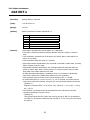
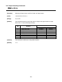
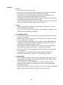
REVISION
Rev No.
Date
Comment
0.00
2004/01/14
Newly issued
1.00
2005/03/4
“GS g 0”, “GS g 2”, “FS g 3”, “FS g 4”, “GS ( K (fn = 200 ~ 208)”,
“GS ( E (fn = 5:200 ~ 211, 240/fn = 6: 200 ~ 211)”,
“GS I (n = 250, 251)”were deleted
1.02
2005/04/25
Change of code pages
1.03
2006/10/26
Add 4.5 Black Mark Layout and Operating Condition
1.10
2010/02/03
PPU700II is added.
CITIZEN is a registered trade mark of CITIZEN WATCH CO., LTD., Japan.
CITIZEN es una marca registrada de CITIZEN WATCH CO., LTD., Japón.
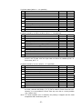
TABLE OF CONTENTS
REVISION ............................................................................................................2
TABLE OF CONTENTS ...........................................................................................1
1. OUTLINE ..........................................................................................................6
1.1 Operation Mode .......................................................................................................6
1.2 Character Set...........................................................................................................6
1.3 Control Commands ..................................................................................................6
1.3.1 Control Command Details .......................................................................................6
1.3.2 How to Send Control Commands ............................................................................6
2. CONTROL COMMANDS .....................................................................................7
2.1 ESC/POS Command List ..........................................................................................7
2.1.1 Description of Items .............................................................................................11
2.2 Command Details ..................................................................................................12
2.2.1 Print Control Commands.......................................................................................12
LF........................................................................................................................................ 12
CR....................................................................................................................................... 12
FF........................................................................................................................................ 13
ESC FF ................................................................................................................................ 14
ESC J n................................................................................................................................ 15
ESC d n ............................................................................................................................... 16
2.2.2 Print Character Commands ...................................................................................17
CAN .................................................................................................................................... 17
ESC SP n ............................................................................................................................. 18
ESC ! n ................................................................................................................................ 19
ESC % n ............................................................................................................................. 21
ESC & s n m [a [p] s×a] m-n+1 .........................................................................................22
ESC – n ............................................................................................................................... 23
ESC ? n ............................................................................................................................... 24
ESC E n ............................................................................................................................... 25
ESC G n............................................................................................................................... 26
ESC M n .............................................................................................................................. 27
ESC R n ............................................................................................................................... 27
ESC V n ............................................................................................................................... 28
ESC t n................................................................................................................................ 29
ESC { n ............................................................................................................................... 30
GS ! n.................................................................................................................................. 31
GS B n................................................................................................................................. 32
GS b n ................................................................................................................................. 33
2.2.3 Print Position Commands......................................................................................34
HT....................................................................................................................................... 34
ESC $ n1 n2 ........................................................................................................................ 35
ESC D [n]k NULL ................................................................................................................36
ESC T n ............................................................................................................................... 37
ESC W xL xH yL yH dxL dxH dyL dyH .................................................................................38
ESC \ nL nH .....................................................................................................................40
ESC a n ............................................................................................................................... 41
GS $ nL nH.......................................................................................................................... 42
-1-
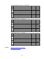
GS L nL nH.......................................................................................................................... 43
GS T n ................................................................................................................................. 44
GS W nL nH ........................................................................................................................ 45
GS \ nL nH .......................................................................................................................47
2.2.4 Line Feed Span Commands ...................................................................................48
ESC 2 .................................................................................................................................. 48
ESC 3 n ............................................................................................................................... 49
2.2.5 Bit Image Commands............................................................................................50
ESC * m n1 n2 [d]k ............................................................................................................50
GS * n1 n2 [d] n1×n2×8....................................................................................................52
GS / m ................................................................................................................................ 53
GS v 0 m xL xH yL yH d1...dk .............................................................................................54
2.2.6 Status Commands .................................................................................................56
DLE EOT n........................................................................................................................... 56
ESC v (At Serial I/F Selection) ..........................................................................................59
GS a n ................................................................................................................................. 60
GS r n.................................................................................................................................. 63
2.2.7 Paper Detecting Commands..................................................................................64
ESC c 3 n............................................................................................................................. 64
ESC c 4 n............................................................................................................................. 65
2.2.8 Panel Switch Commands.......................................................................................66
ESC c 5 n............................................................................................................................. 66
2.2.9 Macro Commands..................................................................................................67
GS :..................................................................................................................................... 67
GS ^ n1 n2 n3 .................................................................................................................... 68
2.2.10 Cutter Commands ...............................................................................................69
ESC i ................................................................................................................................... 69
ESC m ................................................................................................................................. 70
GS V m … (1)...................................................................................................................... 71
GS V m n … (2)................................................................................................................... 71
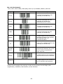
2.2.11 Bar Code Commands ...........................................................................................72
GS H n ................................................................................................................................ 72
GS f n.................................................................................................................................. 73
GS h n................................................................................................................................. 74
GS k m [d1...dk] NULL … (1)..............................................................................................75
GS k m n [d1...dn] … (2) ....................................................................................................75
GS w n ................................................................................................................................ 81
2.2.12 Commands for Non-volatile Memory ..................................................................82
GS ( C pL pH m fn b [c1 c2] [d1...dk] .................................................................................82
fn = 0, 48: Function 0 Erasing Specified Record ..............................................................83
fn = 1, 49: Function 1 Storing Data to Specified Record .................................................83
fn = 2, 50: Function 2 Sending Data Stored in Specified Record ....................................84
fn = 3, 51: Function 3 Sending Use Amount.....................................................................85
fn = 4, 52: Function 4 Sending Remaining Capacity........................................................85
fn = 5, 53: Function 5 Sending Key Code List of Stored Record ......................................86
fn = 6, 54: Function 6 Erasing All User NV Memory Area in a Lump ...............................87
FS p n m ............................................................................................................................. 88
FS q n [xL xH yL yH d1…dk]1 … [xL xH yL yH d1…dk]n ...................................................89
2.2.13 Printer Function Setting Commands ...................................................................92
-2-
GS ( E pL pH fn […] ............................................................................................................92
fn = 1: Function 1 Transferring to Printer Function Setting Mode ..................................93
fn = 2: Function 2 End of Printer Function Setting Mode ................................................93
fn = 3: Function 3 Setting Memory Switch Value.............................................................94
fn = 4: Function 4 Sending the Set Memory Switch Value ..............................................96
fn = 5: Function 5 Setting Customized Value...................................................................98
fn = 6: Function 6 Sending the Set Customized Value................................................... 101
fn = 7: Function 7 Copying User-defined Page .............................................................. 104
fn = 8: Function 8 Defining Data by the Column Format to Character Code Page of
Work Area ........................................................................................................................ 105
fn = 9: Function 9 Defining Data in the Raster Format to the Character Code Page of
Work Area ........................................................................................................................ 106
fn = 10: Function 10 Erasing Data of Character Code Page Data in Work Area ........... 107
fn = 11: Function 11 Setting Communication Conditions of Serial Interface ............... 108
fn = 12: Function 12 Sending the Set Communication Conditions of Serial Interface . 109
fn = 48: Function 48 Erasing Paper Layout .................................................................... 110
fn = 49: Function 49 Setting Paper Layout .................................................................... 111
fn = 50: Function 50 Sending Paper Layout Information .............................................. 112
fn = 255: Function 255 Setting All Contents Set by Printer Function Setting Mode to the
State at Shipment............................................................................................................ 113
GS ( K pL pH fn m .............................................................................................................114
fn = 48: Function 48 Setting Print Control Mode ........................................................... 114
fn = 49: Function 49 Setting Printing Density ............................................................... 115
fn = 50: Function 50 Setting Printing Speed.................................................................. 116
fn = 97: Function 97 Setting Number of Divisions for Head Conducting ...................... 116
GS ( M pL pH fn m ............................................................................................................117
fn = 1, 49: Function 1 Copies the set value stored in work area to the storage area .. 118
fn = 2, 50: Function 2 Copies the set value stored in storage area to the work area .. 118
fn = 3, 51: Function 3 Specifies the auto loading function of the set value at
initialization to be valid or invalid .................................................................................. 119
GS ( N pL pH fn m.............................................................................................................120
fn = 48: Function 48 Selects character color ................................................................. 120
2.2.14 2-dimensional code Commands ........................................................................121
GS ( k pL pH cn fn [parameter] PPU-700II only.............................................................121
fn=65: Function 65 Setting the number of digits of PDF417 ........................................ 122
fn=66: Function 66 Setting the number of steps of PDF417 ......................................... 122
fn=67: Function 67 Setting module width of PDF417 ................................................... 123
fn=68: Function 68 Setting the height of step of PDF417............................................. 123
fn=69: Function 69 Setting error correction level of PDF417 ....................................... 124
fn=70: Function 70 Setting Options for PDF417............................................................ 125
fn=80: Function 80 Storing received data to 2-dimensional code data storage area .. 125
fn=81: Function 81 Printing 2-dimensional code data in 2-dimensional code data
storage area..................................................................................................................... 126
fn=82: Function 82 Sending the size of 2-dimensional code data in 2-dimensional code
data storage area ............................................................................................................ 127
fn=65: Function 165 Specifying QRCode model ............................................................ 128
fn=67: Function 167 Sets the module width of QRCode ............................................... 128
fn=69: Function 169 Setting QRCode error correction level ......................................... 129
fn=80: Function 180 Storing received data to 2-dimensional code data storage area 129
-3-
fn=81: Function 181 Printing 2-dimensional code data in 2-dimensional code data
storage area..................................................................................................................... 130
fn=82: Function 182 Sending the size of 2-dimensional code data in 2-dimensional
code data storage area.................................................................................................... 131
2.2.15 Special Commands ............................................................................................132
ESC n n ............................................................................................................................. 132
ESC Y n1 n2 ...................................................................................................................... 132
GS R 0............................................................................................................................... 133
GS R 1 n............................................................................................................................ 133
GS S .................................................................................................................................. 134
FS ( L pL pH fn m..............................................................................................................135
fn = 48: Function 48 Sending Position Information ...................................................... 136
fn = 66: Function 66 Executing Paper Feeding to Cut Position ..................................... 137
fn = 67: Function 67 Executing Paper Feeding to Initial Position................................. 137
2.2.16 Other Commands ..............................................................................................138
DLE ENQ n ........................................................................................................................ 138
DLE DC4 fn m t (Specification of fn = 8).........................................................................139
ESC = n............................................................................................................................. 140
ESC @ ............................................................................................................................... 141
ESC L ................................................................................................................................ 142
ESC S ................................................................................................................................ 143
ESC RS.............................................................................................................................. 143
GS ( A pL pH n m ..............................................................................................................144
GS I n ............................................................................................................................... 145
GS P x y ............................................................................................................................ 147
GS ( L pL pH m fn [parameter].........................................................................................148
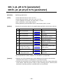
GS 8 L p1 p2 p3 p4 m fn [parameter] ..............................................................................148
fn = 0, 48: Function 48 Sending NV Graphics Memory Capacity ................................... 149
fn = 2, 50: Function 50 Printing Graphics Data Stored in Print Buffer.......................... 149
fn = 3, 51: Function 51 Sending the Remaining Amount of NV Graphics Memory ....... 150
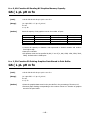
fn = 64: Function 64 Sending Key Code List of Defined NV Graphics ........................... 151
fn = 65: Function 65 Erasing All Data of NV Graphics in a Lump .................................. 152
fn = 66: Function 66 Erasing Specified NV Graphics Data............................................. 152
fn = 67: Function 67 Defining Raster Type Graphics Data to NV Memory .................... 153
fn = 69: Function 69 Printing Specified Graphics .......................................................... 154
fn = 112: Function 112 Storing Raster Type Graphics Data to Print Buffer.................. 155
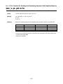
GS ( L pL pH m fn a bx by c xL xH yL yH d1...dk ..............................................................155
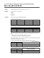
GS C 0 n m........................................................................................................................ 156
GS C 1 aL aH bL bH n r .....................................................................................................157
GS C 2 nL nH..................................................................................................................... 157
GS C ; sa ; sb ; sn ; sr ; sc ; ...............................................................................................158
GS c .................................................................................................................................. 158
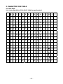
3. CHARACTER CODE TABLE ............................................................................159
3.1 Code Page ............................................................................................................159
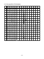
3.1.1 Code page 00H to 7FH & PC437 (USA, Europe Standard)...................................159
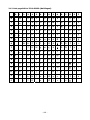
3.1.2 Code page 00H to 7FH & Katakana .....................................................................160
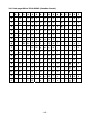
3.1.3 Code page 00H to 7FH & PC850 (Multilingual) ...................................................161
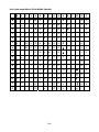
3.1.4 Code page 00H to 7FH & PC860 (Portuguese)....................................................162
3.1.5 Code page 00H to 7FH & PC863 (Canadian-French)...........................................163
-4-
3.1.6 Code page 00H to 7FH & PC865 (Nordic) ...........................................................164
3.1.7 Code page 00H to 7FH & PC852 (Eastern Europe)..............................................165
3.1.8 Code page 00H to 7FH & PC866 (Russian) .........................................................166
3.1.9 Code page 00H to 7FH & PC857(Turkish) ...........................................................167
3.1.10 Code page 00H to 7FH & PC864 (Arabic)..........................................................168
3.1.11 Code page 00H to 7FH & Windows Code page..................................................169
3.2 International Character Code Table ....................................................................170
4. APPENDIX....................................................................................................171
4.1 Explanation on PAGE MODE ................................................................................171
4.1.1 Overview .............................................................................................................171
4.1.2 Values Set by Each Command in STANDARD MODE and PAGE MODE.................171
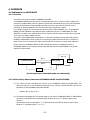
4.1.3 Mapping of Print Data in the Print Area..............................................................172
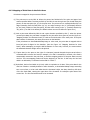
4.1.4 Example of Using PAGE MODE ............................................................................174
4.2 Bidirectional Parallel Interface ...........................................................................177
4.2.1 Parallel Interface Communication Mode.............................................................177
4.2.2 Interfacing Phases ..............................................................................................178
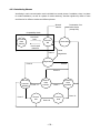
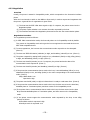
4.2.3 Negotiation .........................................................................................................179
4.3 Identification of Send Status ..............................................................................186
4.4 Memory Switch ....................................................................................................187
4.4.1 Memory Switches................................................................................................187
4.4.2 Details of Memory Switches................................................................................188
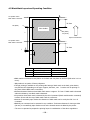
4.5 Black Mark Layout and Operating Condition.......................................................198
-5-
1. OUTLINE
1.1 Operation Mode
PPU-700 has ESC/POSTM as control commands.
1.2 Character Set
All print data sent from the host computer to the printer are automatically converted to one-byte
alphanumeric or katakana characters (ANK) or two-byte Kanji corresponding to the characters and
symbols.
NOTE: For the contents of character set, refer to “3. Character Code Table” of this document.
1.3 Control Commands
1.3.1 Control Command Details
Control Commands are used for controlling the operations of the printer such as starting/stopping of
printing, line feeding, paper feeding, etc. They control all functions related to printing, such as type
of characters, enlargement of characters or setting of format.
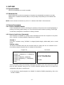
1.3.2 How to Send Control Commands
Some methods are available for sending Control Commands from the host computer to the printer.
Here, a method of sending by BASIC programming is explained.
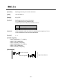
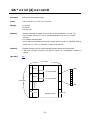
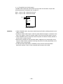
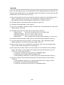
Example 1
Let’s print a character string “CITIZEN” in enlarged (double-height, double-width) and in normal
format.
Program coding
The Control Command shows that the command name for setting the size of a character is GS !.
Let’s make a program using this code. An example is shown below.
Program List
10
20
30
40
50
60
70
Print Result
A$="CITIZEN"
LPRINT CHR$(&H1D);"!"; CHR$(&H33);
LPRINT A$;
LPRINT CHR$(&HA); CHR$(&HA);
LPRINT CHR$(&H1D);"!"; CHR$(&H00);
LPRINT A$;
END
CITIZEN
CITIZEN
In lines 20 and 50, setting and canceling of enlarging a character is sent. As a result, lines 30 and 60
print the same character string but line 30 prints enlarged characters and line 60 cancels the
enlargement and prints in normal format.
* In this document, sample programs are in BASIC. For details of BASIC programming, refer to the
manual for BASIC.
-6-
2. CONTROL COMMANDS
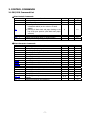
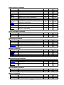
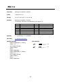
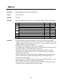
2.1 ESC/POS Command List
○Print Control Commands
Command
Function
LF
Printing and paper feed
CR
Back to printing
(1) Printing in PAGE MODE and returning to
STANDARD MODE (at the selection of PAGE
MODE)
FF
(2) Printing of Black mark and paper feeding to the
top of the print position (with Black mark paper
selected)
ESC FF
Printing data in PAGE MODE
ESC J
Printing and feeding paper in minimum pitch
ESC d
Printing and feeding the paper by “n” lines
○Print Character Commands
Command
Function
CAN
Canceling print data in PAGE MODE
ESC SP
Setting the right spacing of the character
ESC !
Collectively specifying the printing mode
ESC %
Specifying/canceling download character set
ESC &
Defining the download characters
ESC -
Specifying/canceling underline
ESC ?
Deleting download characters
ESC E
Specifying/canceling emphasis printing
ESC G
Specifying/canceling double strike printing
ESC M
Selection of character fonts
ESC R
Selecting the international character set
ESC V
Specifying/canceling 90°-right-turned characters
ESC t
Selecting the character code table
ESC {
Specifying/canceling the inverted characters
GS !
Specifying the character size
Specifying/canceling the black/white inverted
GS B
printing
GS b
Specifying/canceling the smoothing
-7-
MODE
S・P
S・P
GS P
P
P
S・P
S・P
MODE
P
S・P
S・P
S・P
S・P
S・P
S・P
S・P
S・P
S・P
S・P
S
S・P
S
S・P
Page
12
12
13
○
GS P
○
14
15
16
Page
17
18
19
21
22
23
24
25
26
27
27
28
29
30
31
S・P
32
S・P
33
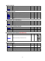
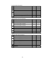
○Print Position Commands
Command
Function
HT
Horizontal tab
ESC $
Specifying the absolute positions
ESC D
Setting horizontal tab position
Selecting the character printing direction in PAGE
ESC T
MODE
ESC W
Defining the print area in PAGE MODE
ESC \
Specifying the relative position
ESC a
Aligning the characters
Specifying the absolute vertical position of
GS $
characters in PAGE MODE
GS L
Setting the left margin
GS T
Moving print position to top of the line
GS W
Setting the print area width
Specifying the relative vertical position of a
GS \
character in PAGE MODE
MODE
S・P
S・P
S・P
GS P
○
P
Page
34
35
36
37
P
S・P
S
○
○
38
40
41
P
○
42
S
S
S・P
○
○
43
44
45
S・P
○
47
○Line Feed Span Commands
Command
Function
ESC 2
Specifying 1/6-inch line feed rate
ESC 3
Setting line feed rate of minimum pitch
MODE
S・P
S・P
GS P
Page
48
49
○Bit Image Commands
Command
Function
ESC *
Specifying the bit image mode
GS *
Defining the download bit image
GS /
Printing the downloaded bit image
GS v 0
Printing of raster bit image
MODE
S・P
S・P
S・P
S
GS P
Page
50
52
53
54
○Status Commands
Command
Function
DLE EOT
Sending status in real-time
ESC v
Sending printer status
GS a
Enabling/disabling ASB (Automatic Status Back)
GS r
Sending status
MODE
S・P
S・P
S・P
S・P
GS P
Page
56
59
60
63
MODE
GS P
Page
○Paper Detecting Commands
Command
Function
Selecting the Paper Sensor valid for Paper-end
ESC c 3
signal output
Selecting the Paper Near-end Sensor valid for print
ESC c 4
stop
○
S・P
64
S・P
65
○Panel Switch Commands
Command
Function
ESC c 5
Enabling/disabling the panel switches
MODE
S・P
GS P
Page
66
○Macro Commands
Command
Function
GS :
Starting/ending macro definition
GS ^
Executing the macro
MODE
S・P
S・P
GS P
Page
67
68
-8-
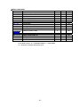
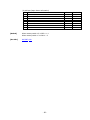
○Cutter Commands
Command
Function
ESC i
Full cutting of paper
ESC m
Full cutting of paper
GS V
Cutting the paper
○Bar Code Commands
Command
Function
GS H
Selecting of printing position of HRI characters
GS f
Selecting the font of HRI characters
GS h
Specifying the height of the bar code
GS k
Printing the bar code
Specifying the horizontal size (magnification) of bar
GS w
code
MODE
S
S
S・P
GS P
MODE
S・P
S・P
S・P
S・P
GS P
○
S・P
Page
69
70
71
Page
72
73
74
75
81
○Commands for Non-volatile Memory
Command
Function
GS ( C
Editing user NV memory
FS p
Printing the download NV bit images
FS q
Defining the download NV bit image
MODE
S
S
S
GS P
Page
82
89
88
○Printer Function Setting Commands
Command
Function
GS ( E
Printer function setting command
GS ( K
Selecting print control method
GS ( M
Customizing the printer
GS ( N
Designating font attribute
MODE
S
S
S
S
GS P
Page
92
114
117
120
MODE
GS P
Page
エラー!
ブック
マーク
が定義
されて
いませ
ん。
GS P
Page
132
132
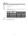
○2-dimensional Code Commands (PPU-700II only)
Command
GS ( k
Function
Setting and printing 2-dimensional code
○Special Commands
Command
Function
ESC n
Setting the remaining amount of printout
Specifying length of paper feed after black mark
ESC Y
detection
GS R 0
Collect the receipt
GS R 1
Setting receipt collection timer
GS S
Detecting a black mark
FS ( L
Controlling black mark paper
-9-
S・P
MODE
S
S
S
S
S
S
133
133
134
135
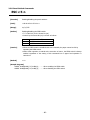
○Other Commands
Command
Function
DLE ENQ
Real-time request to printer
DLE DC4
Buffer clear
ESC =
Data input control
ESC @
Initializing the printer
ESC L
Selecting PAGE MODE
ESC S
Selecting STANDARD MODE
ESC RS
Sound buzzer
GS ( A
Execution of test printing
GS I
Sending the printer ID
GS P
Specifying the basic calculation pitch
GS ( L
Specifying graphics data
GS 8 L
GS C 0
Setting counter print mode
GS C 1
Setting counter mode (A)
GS C 2
Setting counter value
GS C ;
Setting counter mode (B)
GS c
Print the counter
In the Mode column: S = STANDARD MODE, P = PAGE MODE
O = shows the command affected by GS P.
- 10 -
MODE
S・P
S・P
S・P
S・P
S
P
S・P
S
S・P
S・P
GS P
Page
138
139
140
141
142
143
143
144
145
147
S
148
S・P
S・P
S・P
S・P
S・P
156
157
157
158
158
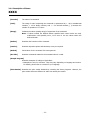
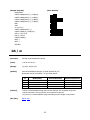
2.1.1 Description of Items
XXXX
[Function]
The name of a command.
[Code]
The string of codes comprising the command is represented by < >H for hexadecimal
numbers, < >B for binary numbers, and < > for decimal numbers, [ ] k denotes the
number of repetition of “k” times.
[Range]
Indicates the values (setting range) of arguments of the command.
Note: If values outside the defined domain specified with control codes are used,
malfunctions could possibly occur, so be sure to use the values within the
defined domain.
[Outline]
Describes the functions of the command.
[Caution]
Describes important points and cautionary notes, as required.
[Default]
Initial values for the command if it has arguments.
[See Also]
Describes commands related to the command when it is used.
[Sample Program]
Describes examples of coding on Quick-Basic.
* Examples are only for reference. They may vary depending on language and version.
For details, please refer to a manual in your language.
[Print Results] Describes the print results obtained by executing the above programs. However, the
print results shown are different in scale from actual print results.
- 11 -
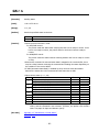
2.2 Command Details
2.2.1 Print Control Commands
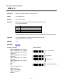
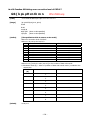
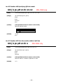
LF
[Function]
Printing and paper feed
[Code]
<0A>H
[Outline]
Prints data inside the print buffer and feeds paper based on the line feed amount having
been set.
[Caution]
After this command is executed, the beginning of the line is taken as the start position
for the next point.
[See Also]
ESC2, ESC3
[Sample Program]
LPRINT "AAA"; CHR$(&HA);
LPRINT "BBB"; CHR$(&HA); CHR$(&HA);
LPRINT "CCC"; CHR$(&HA);
[Print Results]
AAA
BBB
Print and line feed
Print and line feed
Line feed only
CCC
Print and line feed
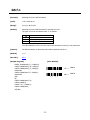
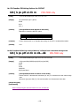
CR
[Function]
Back to printing
[Code]
<0D>H
[Outline]
(1) When memory switch 1-5 is OFF: This command is ignored.
(2) When memory switch 1-5 is ON: The same operation as LF is executed.
[See Also]
LF
[Sample Program]
LPRINT "AAA"; CHR$(&HD);
LPRINT "BBB"; CHR$(&HD);
LPRINT CHR$(&HD);
LPRINT "CCC"; CHR$(&HD);
[Print Results]
In case of (2)
AAA
BBB
Print and line feed
Print and line feed
Line feed only
CCC
- 12 -
Print and line feed
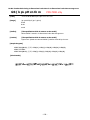
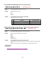
FF
[Function]
(1) Printing in PAGE MODE and returning to STANDARD MODE (at the selection of PAGE
MODE)
(2) Printing of Black mark and paper feeding to the top of the print position (with Black
mark paper selected)
[Code]
<0C>H
(1) At selection of PAGE MODE
[Outline]
Executes a batch printout of the data mapped in the entire print area, and then returns
to STANDARD MODE.
[Caution]
• All mapped data is erased after printout.
• The print area set up by ESC W is initialized.
• This command does not execute a paper cut.
• After this command is executed, the beginning of the line is taken as the start position
for the next print.
• This command is only effective when the PAGE MODE is selected.
[See Also]
Appendix 4.1.4 “Example of Using PAGE MODE”
ESC FF, ESC L, ESC S
(2) At selection of Black mark paper (valid only for Black mark specification)
[Outline]
This command prints the data in the printer buffer and searches for the head of the
next Black mark (Black mark position)
[Caution]
• This command does not execute a paper cut.
• After this command is executed, the beginning of the line is taken as the start position
for the next print.
- 13 -
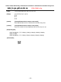
ESC FF
[Function]
Printing data in PAGE MODE
[Code]
<1B>H<0C>H
[Outline]
Executes a batch printout of the data mapped in the entire print area in PAGE MODE.
[Caution]
• This command is only effective when PAGE MODE is selected.
• Mapped data, as well as the ESC T and ESC W settings, and the character mapping
position are held even after printing.
[See Also]
Appendix 4.1 “Explanation on PAGE MODE”
FF, ESC L, ESC S
- 14 -
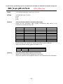
ESC J n
[Function]
Printing and feeding paper in minimum pitch
[Code]
<1B>H<4A>H<n>
[Range]
0≦n≦255
[Outline]
Prints the data held in the print buffer and feeds paper by [n ・basic calculation pitch]
inches.
[Caution]
• After this command is executed, the beginning of the line is taken as the start position
for the next print.
• The line feed width can be set separately for the STANDARD and PAGE MODES.
• This command does not affect the line feed width defined by ESC 2 or ESC 3.
• The basic calculation pitch is set by GS P.
• Fractions resulting from calculation are corrected with the minimum pitch of the
mechanism, and the remainder is omitted.
• In STANDARD MODE, this command uses the vertical (paper feed direction) basic
calculation pitch (y).
• In PAGE MODE, this command acts differently depending on the start point:
(1) If the start point specified by ESC T is top left or bottom right, the command
uses the vertical (paper feed direction) basic calculation pitch (y).
(2) If the start point specified by ESC T is top right or bottom left, the command
uses the horizontal (perpendicular to the paper feed direction) basic calculation
pitch (x).
• The maximum settable line feed width is 1016 mm (40 inches). A setting greater than
this maximum is trimmed to the maximum.
[Default]
The initial value is not defined.
[Sample Program]
Refer to Sample Program and Print Results for ESC 2.
- 15 -
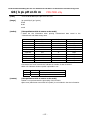
ESC d n
[Function]
Printing and feeding the paper by “n” lines
[Code]
<1B>H<64>H<n>
[Range]
0≦n≦255
[Outline]
Prints data in the print buffer and feeds paper by “n” lines. Specified lines do not
remain.
[Caution]
• After this command is executed, the beginning of the line is taken as the start position
for the next print.
• If [n×line feed width] exceeds approximately 1016 mm, this command feeds paper by
approximately 1016 mm (40 inches).
[Default]
The initial value is not defined.
[Sample Program]
LPRINT "AAAAA";
LPRINT CHR$(&H1B);"d";CHR$(2);
LPRINT "AAAAA";CHR$(&HA);
[Print Results]
AAAAA
2/6-inch line feed
AAAAA
- 16 -
2.2.2 Print Character Commands
CAN
[Function]
Canceling print data in PAGE MODE
[Code]
<18>H
[Outline]
Erases all data contained in the currently effective print area in PAGE MODE.
[Caution]
• This command is only effective when PAGE MODE is selected.
• If the previously established print area overlaps the currently effective print area, the
overlapped data in the previously established area will be erased.
[See Also]
Appendix 4.1 “Explanation on PAGE MODE”
ESC L, ESC W
- 17 -
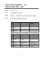
ESC SP n
[Function]
Setting the right spacing of the character
[Code]
<1B>H<20>H<n>
[Range]
0≦n≦255
[Outline]
Sets the right spacing of character to [n×basic calculation pitch] inches.
[Caution]
• If the horizontal magnification of character is 2 or more, the right spacing increases
with the magnification.
• Does not affect Kanji.
• The right spacing can be set separately for the STANDARD and PAGE MODES.
• The basic calculation pitch is set by GS P. Once defined, the right spacing is not
changed if the basic calculation pitch is changed by GS P.
• Fractions resulting from calculation are corrected with the minimum pitch of the
mechanism, and the remainder is omitted.
• In STANDARD MODE, this command uses the horizontal basic calculation pitch (x).
• In PAGE MODE, the basic calculation pitch used by this command depends on the start
point:
(1) If the start point specified by ESC T is top left or bottom right, the command uses
the horizontal basic calculation pitch (x).
(2) If the start point specified by ESC T is top right or bottom left, the command uses
the vertical basic calculation pitch (y).
• The maximum right spacing is capable of approximately 31.906 mm (255/203 inches).
A setting greater than this maximum is trimmed to the maximum.
[Default]
n=0
[See Also]
GS P
[Sample Program]
LPRINT
LPRINT
LPRINT
LPRINT
LPRINT
LPRINT
[Print Results]
CHR$(&H1B);" "; CHR$(0);
"AAAAA"; CHR$(&HA);
CHR$(&H1B);" "; CHR$(1);
"AAAAA"; CHR$(&HA);
CHR$(&H1B);" "; CHR$(12);
"AAAAA"; CHR$(&HA);
- 18 -
AAAAA
A A A A A
A A A A A
0-dot space
1-dot space
12-dots space
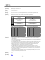
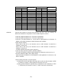
ESC ! n
[Function]
Collectively specifying the printing mode
[Code]
<1B>H<21>H<n>
[Range]
0≦n≦255
[Outline]
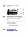
Printing mode is assigned.
Bit
Function
0
1
2
3
4
5
6
7
Character Font
Undefined
Undefined
Emphasis
Double height
Double width
Undefined
Underline
Value
0
Font A (12×24)
――
――
Canceled
Canceled
Canceled
――
Canceled
1
Font B(9×17)
――
――
Specified
Specified
Specified
――
Specified
[Caution]
• With double height and double width being specified simultaneously, quadruple
characters are created.
• An underline is attached to the full character width, which, however, is not attached to
the part having been skipped by the horizontal tab (HT). Neither is it attached to
90°-right-turned characters.
• The underline width is as specified by the ESC – command. (The default setting is 1
dot width.)
• Setting by this command is invalid for Kanji except setting and canceling of enhanced
printing.
• In case characters with different vertical magnification ratios coexist on the same line,
they are printed on the same base line.
• ESC E, ESC M, ESC –, and GS ! can individually set or cancel the mode but the
command processed last is valid.
• Setting or cancelling of enhanced 3rd bit is valid for alphanumric and kana and kanji.
Other print mode is valid only for alphanumeric and kana characters.
[Default]
n=0
[See Also]
ESC E, ESC M, ESC -, GS !
- 19 -
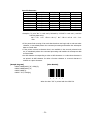
[Sample Program]
LPRINT CHR$(&H1B);"!";CHR$(&H00);"H";
LPRINT CHR$(&H1B);"!";CHR$(&H01);"H";
LPRINT CHR$(&H1B);"!";CHR$(&H08);"H";
LPRINT CHR$(&H1B);"!";CHR$(&H10);"H";
LPRINT CHR$(&H1B);"!";CHR$(&H20);"H";
LPRINT CHR$(&H1B);"!";CHR$(&H80);"H";
LPRINT CHR$(&H1B);"!";CHR$(&HB9);"H";
LPRINT CHR$(&HA);
[Print Results]
Font B + Emphasis +
Quadruple + Underline
Font
Font
Font
Font
Font
Font
A
A
A
A
B
A
+
+
+
+
Underline
Double width
Double height
Emphasis
- 20 -
ESC % n
[Function]
Specifying/canceling download character set
[Code]
<1B>H<25>H<n>
[Range]
0≦n≦255
[Outline]
Specifying/canceling download characters.
• “n” is valid only for the lowest bit (n0).
• Control by the lowest bit (n0) is shown as follows:
n0
0
1
[Default]
n=0
[See Also]
ESC &
Function
Canceling download character set
Specifying download character set
[Sample Program]
GOSUB SETCHR
LPRINT CHR$(&H1B);"%";CHR$(0);
LPRINT "@A";CHR$(&HA);
LPRINT CHR$(&H1B);"%";CHR$(1);
LPRINT "@A";CHR$(&HA);
END
SETCHR:
LPRINT CHR$(&H1B);"&";
LPRINT CHR$(3);"@";"A";
FOR J=1 TO 2
READ REP
LPRINT CHR$(REP);
FOR I=1 TO REP*3
READ D
LPRINT CHR$(D);
NEXT I
NEXT J
RETURN
DATA 6
DATA &HFF,&H80,&H00
DATA &H80,&H80,&H00
DATA &H80,&H80,&H00
DATA &H80,&H80,&H00
DATA &HFF,&HFF,&HFF
DATA &HFF,&HFF,&HFF
DATA 12
DATA &HFF,&HFF,&HFF
DATA &H80,&H07,&HF9
DATA &H80,&HFF,&HF9
DATA &H87,&HFE,&H01
DATA &H9F,&H06,&H01
DATA &HF8,&H06,&H01
DATA &HF8,&H06,&H01
DATA &H9F,&H06,&H01
DATA &H87,&HFE,&H01
DATA &H80,&HFF,&HF9
DATA &H80,&H07,&HF9
DATA &HFF,&HFF,&HFF
[Print Results]
@A
A
Internal character set
Download character
- 21 -
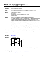
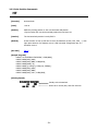
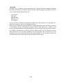
ESC & s n m [a [p] s×a] m-n+1
[Function]
Defining the download characters
[Code]
<1B>H<26>H<s>H<n>H<m>H[<a>H<p1>H<p2>…<ps×a>]m-n+1
[Range]
s=3(FontA, B) s=2(FontC)
32≦n≦m≦126
0≦a≦12(FontA), 0≦a≦9 (FontB), 0≦a≦8 (FontC)
0≦p1…ps×a≦255
[Outline]
Defines the font of download characters of alphanumeric characters.
• “s” indicates the number of bytes in vertical direction. “n” indicates the start character
code and “m” the end character code. To define only one character, set n = m.
Character codes definable includes 95 ASCII codes in total in the range of <20>H to
<7E>H.
• “a” indicates the number of dots to be defined in horizontal direction. “p” is the data
to be defined, which indicate a pattern equal to “a” dots in horizontal direction from
the left end. The rest of the pattern on the right side is filled with space.
• The number of data to be defined is “s ・a”. Download characters thus defined remain
valid until redefinition, execution of ESC @, GS *, FS q, GS ( A, deletion by ESC ?, or
power OFF is performed.
[Caution]
Download characters and download bit images cannot be defined simultaneously.
Running this command clears the definition of the download bit image.
[Default]
Same as the internal character set.
[See Also]
ESC %, ESC ?
12dot
[Example]
24dot
p1
p4
p34
p2
p5
p35
p3
p6
p36
MSB
LSB
FontA
Create each data bit by setting “1” for a printed dot and “0” for an unprinted dot.
[Sample Program]
Refer to Sample Program and Print Results for ESC %.
- 22 -
ESC – n
[Function]
Specifying/canceling underline
[Code]
<1B>H<2D>H<n>
[Range]
0≦n≦2, 48≦n≦50
[Outline]
Specifying/canceling an underline.
n
0,48
1,49
2,50
Function
Canceling underline
Setting 1-dot width underline
Setting 2-dot width underline
[Caution]
• An underline is attached to the full character width. It is, however, not attached to the
part having been skipped by horizontal tab (HT) command.
• An underline is not attached to 90°-right-turned characters and white-on-black
character.
• Underline can also be specified/canceled by ESC ! but the setting of command last
processed is valid.
• Specifying/canceling by this command is not valid for kanji.
• Underline width is constant in the specified thickness regardless of the character size.
[Default]
n=0
[See Also]
ESC !, FS -
[Sample Program]
LPRINT
LPRINT
LPRINT
LPRINT
CHR$(&H1B);"-";CHR$(0);
"AAAAA";
CHR$(&H1B);"-";CHR$(1);
"AAAAA";CHR$(&HA);
- 23 -
[Print Results]
Underline canceled
AAAAAAAAAA
Underline specified
ESC ? n
[Function]
Deleting download characters
[Code]
<1B>H<3F>H<n>
[Range]
32≦n≦126
[Outline]
Deletes the downloaded characters of specified code.
[Caution]
• The character “n” indicates the character code used to delete the defined pattern.
After the deletion, characters are printed in the same pattern as the internal
characters.
• This command deletes the code-defined pattern of the character font selected by
ESC !.
• This command is ignored if the specified character code is undefined.
[See Also]
ESC &, ESC %
- 24 -
ESC E n
[Function]
Specifying/canceling emphasis printing
[Code]
<1B>H<45>H<n>
[Range]
0≦n≦255
[Outline]
Specifying/canceling the emphasized characters.
• “n” is valid only for the lowest bit (n0).
• Control by the lowest bit (n0) is shown as follows:
n0
0
1
Function
Canceling emphasis printing
Specifying emphasis printing
[Caution]
• Emphasis printing can also be specified/canceled by ESC ! but the setting of command
last processed is valid.
• Valid for all character types except HRI characters.
[Default]
n=0
[See Also]
ESC !
[Sample Program]
LPRINT CHR$(&H1B);"E"; CHR$(0);
LPRINT "AAABBB"; CHR$(&HA);
LPRINT CHR$(&H1B);"E"; CHR$(1);
LPRINT "AAABBB"; CHR$(&HA);
[Print Results]
AAABBB
AAABBB
- 25 -
Emphasis canceled
Emphasis specified
ESC G n
[Function]
Specifying/canceling double strike printing
[Code]
<1B>H<47>H<n>
[Range]
0≦n≦255
[Outline]
Specifying/canceling the double strike printing.
• “n” is valid only for the lowest bit (n0).
• Control by the lowest bit (n0) is shown as follows:
n0
0
1
Function
Canceling double strike printing
Specifying double strike printing
[Caution]
• With this printer, double-strike printing and emphasis printing provide completely the
same results.
• Valid for all character types except HRI characters.
[Default]
n=0
[See Also]
ESC E
[Sample Program]
LPRINT CHR$(&H1B);"G"; CHR$(0);
LPRINT "AAABBB"; CHR$(&HA);
LPRINT CHR$(&H1B);"G"; CHR$(1);
LPRINT "AAABBB"; CHR$(&HA);
[Print Results]
AAABBB
AAABBB
- 26 -
Double strike printing canceled
Double strike printing specified
ESC M n
[Function]
Selection of character fonts
[Code]
<1B>H<4D>H<n>
[Range]
0≦n≦2, 48≦n≦50
[Outline]
Selects character fonts.
n
0,48
1,49
2,50
Function
Selection of font A(12×24)
Selection of font B(9×24)
Selection of font C(8×16)
[Caution]
ESC ! can also select fonts, but the setting made by the command that has last been
processed becomes valid.
[Default]
n=0
[See Also]
ESC !
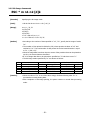
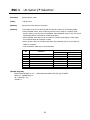
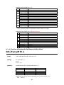
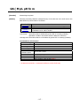
ESC R n
[Function]
Selecting the international character set
[Code]
<1B>H<52>H<n>
[Range]
0≦n≦13
[Outline]
Depending on the value of “n”, one of the following character sets is specified;
n
0
1
2
3
4
5
6
Character Set
U.S.A
France
Germany
U.K
Denmark I
Sweden
Italy
n
7
8
9
10
11
12
13
Character Set
Spain I
Japan
Norway
Denmark II
Spain II
Latin America
Korea
[Default]
n = 0 (Overseas), n = 8 (Domestic)
[See Also]
3.2 “International Character Code Table”
- 27 -
ESC V n
[Function]
Specifying/canceling 90°-right-turned characters
[Code]
<1B>H<56>H<n>
[Range]
0≦n≦2, 48≦n≦50
[Outline]
Specifying/canceling 90°-right-turned characters.
n
0,48
1,49
2,50
Function
Canceling 90°-right-turned characters
Specifying 90°-right-turned characters
[Caution]
• No underlines are attached to 90°-right-turned characters.
• This command does not affect PAGE MODE but setting is maintained.
[Default]
n=0
[Sample Program]
LPRINT CHR$(&H1B);"V"; CHR$(0);
LPRINT "AAAAA";
LPRINT CHR$(&H1B);"V"; CHR$(1);
LPRINT "AAAAA"; CHR$(&HA);
[Print Results]
90° rotation canceled
90° rotation specified
- 28 -
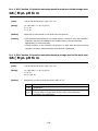
ESC t n
[Function]
Selecting the character code table
[Code]
<1B>H<74>H<n>
[Range]
0≦n≦9, 16≦n≦19, n=26, 40, 255
[Outline]
Selecting the character code table.
The character code table is selected based on the value of “n”.
n
0
1
2
3
4
5
6,18
Character Code Table
Code page PC437
Katakana
Code page PC850
Code page PC860
Code page PC863
Code page PC865
Code page PC852
[Default]
n = 0 (Overseas), n = 1 (Domestic)
[See Also]
3. “Character Code Table”
[Sample Program]
LPRINT CHR$(&H1B);"t"; CHR$(0);
LPRINT "n=0 ";
FOR C=&HB1 TO &HB5
LPRINT CHR$(C);
NEXT C
LPRINT CHR$(&HA);
LPRINT CHR$(&H1B);"t"; CHR$(1);
LPRINT "n=1 ";
FOR C=&HB1 TO &HB5
LPRINT CHR$(C);
NEXT C
LPRINT CHR$(&HA);
n
7,17
8
9,16
19
26
40
255
Character Code Table
Code page PC866
Code page PC857
Windows code
Code page PC858
Thai code 18
CodepagePC864
Space page(For user setting)
[Print Results]
n=0
n=1
- 29 -
n=0
アイウエオ
n=1
ESC { n
[Function]
Specifying/canceling the inverted characters
[Code]
<1B>H<7B>H<n>
[Range]
0≦n≦255
[Outline]
Specifying/canceling inverted characters.
• “n” is valid only for the lowest bit (n0).
• Control by the lowest bit (n0) is shown as follows:
n0
0
1
Condition
Canceling inverted characters.
Specifying inverted characters.
[Caution]
• This command is valid only when it is specified at the beginning of a line.
• This command does not affect the PAGE MODE.
[Default]
n=0
[Sample Program]
LPRINT CHR$(&H1B) ;"{"; CHR$(0);
LPRINT "TEN"; CHR$(&HA);
LPRINT "ELEVEN"; CHR$(&HA);
LPRINT CHR$(&H1B) ;"{"; CHR$(1);
LPRINT "TEN"; CHR$(&HA);
LPRINT "ELEVEN"; CHR$(&HA);
[Print Results]
Inversion canceled
Paper feed direction
Inversion specifie
- 30 -
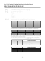
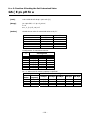
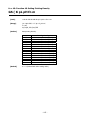
GS ! n
[Function]
Specifying the character size
[Code]
<1D>H<21>H<n>
[Range]
0≦n≦255 where: 1≦vertical magnification≦8, 1≦horizontal magnification≦8
[Outline]
Specifies the character size (Vertical and horizontal magnification).
Bit
0
1
2
3
4
5
6
7
Function
Hex. Number
Value
Decimal Number
Vertical magnification
specification
Refer to Table 2,
“Vertical Magnification”.
Horizontal magnification
specification
Refer to Table 1,
“Horizontal Magnification”.
Table 1 Horizontal Magnification
Hex. Decimal
Magnification
1×(Standard)
00
0
2×(Double width)
10
16
20
32
3×
30
48
4×
40
64
5×
50
80
6×
60
96
7×
70
112
8×
Table 2 Vertical Magnification
Hex. Decimal Magnification
1×(Standard)
00
0
2×(Double)
01
1
02
2
3×
03
3
4×
04
4
5×
05
5
6×
06
6
7×
07
7
8×
[Caution]
• This command is valid for all characters (alphanumeric, kana, and kanji) except for
HRI characters.
• This command is ignored if either the vertical magnification or horizontal magnification
is out of the defined range.
• In STANDARD MODE, the vertical direction is defined as the paper feed direction, and
the horizontal direction is defined as the direction perpendicular to the paper feed.
• Setting memory SW 3-7 to ON allows the horizontal and vertical relations to be
interchanged when 90°-right-turnning of character is specified.
• In PAGE MODE, the vertical direction means the top-bottom direction of each
character. The horizontal direction means the side-to-side direction of each character.
• If characters of different vertical magnification are contained in a line, the baseline of
each character is lined up.
• Horizontal and vertical magnification can also be specified/canceled by ESC ! but the
setting of command last processed is valid.
[Default]
n=0
[See Also]
ESC !
- 31 -
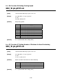
GS B n
[Function]
Specifying/canceling the black/white inverted printing
[Code]
<1D>H<42>H<n>
[Range]
0≦n≦255
[Outline]
This command specifies or cancels the black/white inverted printing.
• “n” is valid only for the lowest bit (n0).
• Control by the lowest bit (n0) is shown as follows:
n0
0
1
Function
The black/white inverted printing is canceled.
The black/white inverted printing is specified.
[Caution]
• The black/white inversion works on internal and downloaded characters.
• The black/white inversion works also on the right spacing of characters defined by ESC
SP.
• This command does not affect the bit image, downloaded bit image, bar code, HRI
characters, or the skip area specified by HT, ESC $, or ESC \.
• This command does not affect the space between lines.
• Black/white inversion specification takes precedence over underline specification.
Underline printing specified is, therefore, nullified if black/white inversion is specified;
the underline setting, however, remains unchanged.
[Default]
n=0
- 32 -
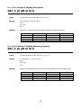
GS b n
[Function]
Specifying/canceling the smoothing
[Code]
<1D>H<62>H<n>
[Range]
0≦n≦255
[Outline]
This command specifies or cancels the smoothing.
• “n” is valid only for the lowest bit (n0).
• Control by the lowest bit (n0) is shown as follows:
n0
0
1
Function
The smoothing is canceled.
The smoothing is specified.
[Caution]
• Smoothing is effective to printer’s internal characters, download characters, and
non-standard characters.
• Smoothing is not effective to characters with either of their vertical or horizontal
magnification is ×1.
[Default]
n=0
[See Also]
ESC !, GS !
- 33 -
2.2.3 Print Position Commands
HT
[Function]
Horizontal tab
[Code]
<09>H
[Outline]
Shifts the printing position to the next horizontal tab position.
• Ignored when the next horizontal tab position has not been set.
[Caution]
The horizontal tab position is set by ESC D.
[Default]
At the selection of font A, tabs are set every 8 characters (at 9th, 17th, 25th, ...) with
right space amount of a character set at 0 and horizontal enlargement rate of a
character set at 1.
[See Also]
ESC D
[Sample Program]
LPRINT "012345678901234567890"; CHR$(&HA);
LPRINT CHR$(&H9);"AAA";
LPRINT CHR$(&H9);"BBB"; CHR$(&HA);
LPRINT CHR$(&H1B);"D";
LPRINT CHR$(3); CHR$(7); CHR$(14); CHR$(0);
LPRINT CHR$(&H9);"AAA";
LPRINT CHR$(&H9);"BBB";
LPRINT CHR$(&H9);"CCC"; CHR$(&HA);
[Printing Result]
012345678901234567890
AAA
BBB
AAA BBB
CCC
Initially set horizontal tab
When set to the 4th, 8th, and 15th columns
- 34 -
ESC $ n1 n2
[Function]
Specifying the absolute positions
[Code]
<1B>H<24>H<n1><n2>
[Range]
0≦n1≦255
0≦n2≦255
[Outline]
The printing start position is specified by the absolute position from the left margin with
the number of dots divided by 256 and quatient specified as “n2” and remainder as
“n1”.
Therefore, the printing start position is designated as [(n1+n2×256)×basic calculation
pitch] from the left margin.
[Caution]
• The basic calculation pitch is set by GS P. After the line feed width is set, if the basic
calculation by GS P leaves a fraction, the fraction is corrected with the minimum pitch
of the mechanism, and the remainder is omitted.
• In STANDARD MODE, this command uses the horizontal (paper feed direction) basic
calculation pitch (x).
• In PAGE MODE, this command acts differently depending on the start point:
(1) If the start point specified by ESC T is top right or bottom left, the command
uses the vertical (paper feed direction) basic calculation pitch (y).
(2) If the start point specified by ESC T is top left or bottom right, the command
uses the horizontal (perpendicular to the paper feed direction) basic calculation
pitch (x). Specification beyond the end of the line is ignored.
[See Also]
ESC \, GS P, GS \,GS $
[Sample Program]
[Print Results]
LPRINT CHR$(&H1B);"$";
Absolute position specified
LPRINT CHR$(0); CHR$(0);"A";
0
50
100
LPRINT CHR$(&H1B);"$";
LPRINT CHR$(50); CHR$(0);"B";
LPRINT CHR$(&H1B);"$";
A
B
LPRINT CHR$(0); CHR$(1);"C"; CHR$(&HA);
A
B
A
LPRINT CHR$(&H1B);"$";
LPRINT CHR$(100); CHR$(0);"A";
Relative position specified -62
LPRINT CHR$(&H1B);"\";
LPRINT CHR$(&HC2); CHR$(&HFF);"B"; CHR$(&HA)
- 35 -
256
C
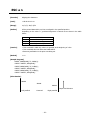
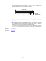
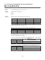
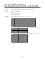
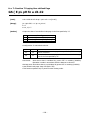
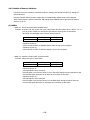
ESC D [n]k NULL
[Function]
Setting horizontal tab position
[Code]
<1B>H<44>H [<n>] k <00>H
[Range]
1≦n≦255
0≦k≦32
[Outline]
Specifying a horizontal tab position.
• “n” indicates the number of columns from the beginning to the horizontal tab position.
Note, however, that “n = set position – 1”. For example, to set the position at 9th
column, n = 8 is to be specified.
• “k” denotes the number of horizontal tab positions you want to set. The tab position is
set at a position where it is “character width ・n” from the beginning of a line. The
character width, at this time, includes the space on the right. In double width
characters, it is made double the ordinary case. Tab positions that can be specified are
maximum 32. Specifying tab positions exceeding this limit is ignored. <n>k, which
denotes a setting position, is input in the increasing order and ends at <00> H.
• ESC D <NULL> clears all the set tab positions. Following clearing, the horizontal tab
(HT) command is ignored.
[Caution]
• When the data, <n>k, is equal to or smaller than its preceding data, <n>k–1, it is
assumed that tab setting is finished. If this is the case, the next data onward will be
processed as normal data.
• When the data, <n>k, exceeds a 1-line print area, set the horizontal tab position, as
“Set column position = Maximum print columns + 1”.
• The horizontal tab position does not change even if the character width is altered after
setting the horizontal tab position.
[Default]
At the selection of font A, tabs are set every 8 characters (at 9th, 17th, 25th, ...) with
right space amount of a character set at 0 and horizontal enlargement rate of a
character set at 1.
[See Also]
HT
[Sample Program]
Refer to Sample Program and Print Results for HT.
- 36 -
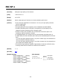
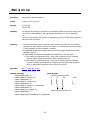
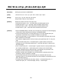
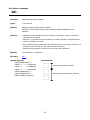
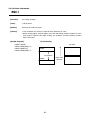
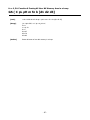
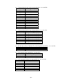
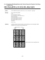
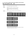
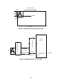
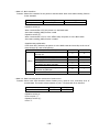
ESC T n
Selecting the character printing direction in PAGE MODE
[Code]
<1B>H<54>H<n>
[Range]
0≦n≦3, 48≦n≦51
0,48
Left to right
1,49
Bottom to top
2,50
Right to left
3,51
Top to bottom
Start Point
Top left
(“A” in the figure)
Bottom left
(“B” in the figure)
Bottom right
(“C” in the figure)
Top right
(“D” in the figure))
A
B
Printing
Direction
Paper feed direction
n
D
[Function]
[Outline]
Selects the direction and start point of character printing in PAGE MODE.
[Caution]
• When STANDARD MODE is selected, this command only executes the internal flagging
of the printer without affecting the printing in STANDARD MODE.
• The character mapping position will be the start point of the print area specified by
ESC W.
• The basic calculation pitch (x or y) used by the following commands varies with the
start point.
(1) If the start point is the top left or bottom right (the characters are mapped in the
direction perpendicular to the paper feed),
• Commands using x: ESC SP, ESC S, ESC \
• Commands using y: ESC 3, ESC J, GS $, GS \
(2) If the start point is the top right or bottom left (the characters are mapped in the
paper feed direction),
• Commands using x: ESC 3, ESC J, GS $, GS \
• Commands using y: ESC SP, ESC S, ESC \
[Default]
n=0
[See Also]
Appendix 4.1 “Explanation on PAGE MODE”
ESC $, ESC L, ESC W, ESC \, GS $, GS P, GS \
- 37 -
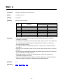
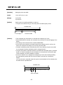
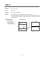
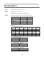
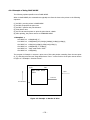
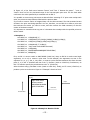
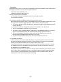
ESC W xL xH yL yH dxL dxH dyL dyH
[Function]
Defining the print area in PAGE MODE
[Code]
<1B>H<57>H<xL><xH><yL><yH><dxL><dxH><dyL><dyH>
[Range]
0≦xL, xH, yL, yH, dxL, dxH, dyL, dyH ≦255
except for dxL=dxH=0 or dyL=dyH=0
[Outline]
Defines the location and size of the print area.
• Horizontal start point = [(xL + xH×256)×basic calculation pitch] inches
• Vertical start point = [(yL + yH×256) ×basic calculation pitch] inches
• Horizontal length = [(dxL + dxH×256)×basic calculation pitch] inches
• Vertical length = [(dyL + dyH×256)×basic calculation pitch] inches
[Caution]
• When STANDARD MODE is selected, this command only executes the internal flagging
of the printer without affecting the printing in STANDARD MODE.
• If the horizontal start point or vertical start point is out of the printable area, this
command is canceled and the next data is handled as normal data.
• If the horizontal length or vertical length is 0, this command is canceled and the next
data is handled as normal data.
• The character mapping position will be the start point specified by ESC T in the print
area.
• If the “horizontal start point + horizontal length” is greater than the horizontal
printable area, the “horizontal printable area – horizontal start point” is taken as the
horizontal length.
• If the “vertical start point + vertical length” is greater than the vertical printable area,
the “vertical printable area – vertical start point” is taken as the vertical length.
• The basic calculation pitch is defined by GS P. Once defined, the print area is not
changed if the basic calculation pitch is changed by GS P.
• Fractions resulting from calculations are corrected with the minimum pitch of the
mechanism, and the remainder is omitted.
• The horizontal start point and horizontal length are calculated with the basic
calculation pitch (x). The vertical start point and vertical length are calculated with the
basic calculation pitch (y).
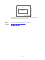
• The figure below illustrates the print area, where X = horizontal start point, Y =
vertical start point, Dx = horizontal length, and Dy = vertical length.
- 38 -
Paper
(X, Y)
Dx
Print Area
(X+Dx-1, Y+Dy-1)
Paper feed direction
Dy
The printable area for this printer is approximately 80.078 mm (640/203 inches)
horizontally and 117 mm (938/203 inches) vertically.
[Default]
xL=xH=yL=yH=0, dxL=64, dxH=2, dyL=126, dyH=6
[See Also]
Appendix 4.1 “Explanation on PAGE MODE”
CAN, ESC L, ESC T, GS P
- 39 -
ESC \ nL nH
[Function]
Specifying the relative position
[Code]
<1B>H<5C>H<nL><nH>
[Range]
0≦nL≦255
0≦nH≦255
[Outline]
This command specifies the next print start position in a relative position with respect to
the current position. The next print start position will be at a point of [(nL+nH×256)
×basic calculation pitch] inches away from the current position.
[Caution]
• Specification of a position outside the print area is ignored.
• If a new position is specified to the right of the current position in the direction of
printing, it should be specified as positive (+). If it is to the left, it should be as
negative (–).
• A negative value is the complement of 65536. For example, to move the position by N
pitches to the left, specify it as:
nL+nH×256 = 65536 – N
• The basic calculation pitch is set by GS P.
• Fractions resulting from calculation are corrected with the minimum pitch of the
mechanism, and the remainder is omitted.
• In STANDARD MODE, this command uses the horizontal basic calculation pitch (x).
• In PAGE MODE, this command acts differently depending on the start point:
(1) If the start point specified by ESC T is top left or bottom right, the command
specifies the relative position in the direction perpendicular to the paper feed (the
character’s side-to-side direction), using the horizontal basic calculation pitch (x).
(2) If the start point is top right or bottom left, the command specifies the relative
position in the paper feed direction (the character’s side-to-side direction), using
the vertical basic calculation pitch (y).
[See Also]
ESC $, GS P
[Sample Program]
Refer to Sample Program and Print Results for ESC $.
- 40 -
ESC a n
[Function]
Aligning the characters
[Code]
<1B>H<61>H<n>
[Range]
0≦n≦2, 48≦n≦50
[Outline]
All the printed data within one line are aligned in the specified position.
Depending on the value “n”, positional alignment is carried out as shown in the table
below:
n
0,48
1,49
2,50
Position
Left end alignment
Centering
Right end alignment
[Caution]
• This command is valid only when it is inputted at the beginning of a line.
• This command does not affect the PAGE MODE.
• Executes justification in the print area being set.
[Default]
n=0
[Sample Program]
LPRINT CHR$(&H1B);"a"; CHR$(0);
LPRINT "AAAAA"; CHR$(&HA);
LPRINT CHR$(&H1B);"a"; CHR$(1);
LPRINT "AAAAA"; CHR$(&HA);
LPRINT CHR$(&H1B);"a"; CHR$(2);
LPRINT "AAAAA"; CHR$(&HA);
[Print Results]
AAAAA
AAAAA
AAAAA
Paper feed direction
Left-justified
Centered
Right-justified
- 41 -
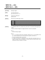
GS $ nL nH
[Function]
Specifying the absolute vertical position of characters in PAGE MODE
[Code]
<1D>H<24>H<nL><nH>
[Range]
0≦nL≦255, 0≦nH≦255
[Outline]
Specifies the vertical position of character at the start point of data development in
PAGE MODE using absolute position based on the start position. The position of vertical
direction of character at the start position of next data development is the position [(nL
+ nH×256)×basic calculation pitch] from the start position.
[Caution]
• This command is ignored except at PAGE MODE selection.
• Absolute position setting exceeding the specified print area is ignored.
• Position in horizontal direction of character at the start position of data development is
not shifted.
• Start point used as the reference is set by ESC T.
• The following operation occurs at the start point of ESC T.
(1) When start point is set at upper left or lower right, the absolute position of paper
feed direction (vertical direction of character) is set. In this case, basic calculation
pitch (y) of vertical direction is used.
(2) When start point is set at upper right or lower left, the absolute position of
vertical direction of paper feed (vertical direction of character) is set. In this case,
basic calculation pitch (x) of horizontal direction is used.
• Basic calculation pitch is set by GS P.
• When fractional number is caused by the calculation, it is corrected by the minimum
pitch of mechanism and the rest is discarded.
[See Also]
ESC $, ESC T, ESC W, ESC \, GS P, GS \
- 42 -
GS L nL nH
[Function]
Setting the left margin
[Code]
<1D>H<4C>H<nL><nH>
[Range]
0≦nL≦255, 0≦nH≦255
[Outline]
This command sets the left margin specified by nL and nH.
The value of the left margin is [(nL+nH×256)×basic calculation pitch] inches.
Printable area
Left margin
Print area width
[Caution]
• This command only works when it is entered at the beginning of a line.
• When PAGE MODE is selected, this command only executes the internal flagging of the
printer.
• The setting of this command does not affect PAGE MODE.
• The maximum settable left margin is equal to the horizontal printable area. A setting
greater than this maximum is trimmed to the maximum.
• The basic calculation pitch is defined by GS P. Once defined, the left margin is not
changed if the basic calculation pitch is changed by GS P.
• The left margin is calculated with the horizontal basic calculation pitch (x) set by GS P.
A fraction resulting from the calculation is corrected with the minimum pitch of the
mechanism, and the remainder is omitted.
• When mapping character data, if the print area specified is not wide enough to
accommodate one character of the current font, only the line for that character data is
handled as follows:
(1) The print area is extended toward the right to be equivalent to one character of
the current font, but not wider than the printable area.
(2) If an area for one character cannot be provided as a result of step (1), the print
area is extended toward the left. (So, the left margin is decreased.)
• When mapping non-character data (bit image, downloaded bit image, raster bit image,
or NV bit image), if the print area specified is narrower than 9-bits, only the line for
that data is handled as follows:
(1) The print area is extended toward the left (so, the left margin is decreased) until
it is 9-dot wide, but not wider than the printable area.
[Default]
nL=0, nH=0
[See Also]
GS P, GS W
- 43 -
GS T n
[Function]
Moving print position to top of the line
[Code]
<1D>H<54>H<n>
[Range]
n=0, 1, 48, 49
[Outline]
Moves print position to top of the line.
• “n” specifies data processing in print buffer at the execution of this command.
n
0,48
1,49
Function
Moves print position after erasing the data in print buffer.
Moves print position after printing the data in print buffer.
• When printing is specified (n = 1, 49), data in the print buffer is printed and line
feeding in accordance with the specified line feed is executed.
• When erasing is specified (n = 0, 48), cancel processing of print data in the print
buffer is executed with other data and setting retained.
- 44 -
GS W nL nH
[Function]
Setting the print area width
[Code]
<1D>H<57>H<nL><nH>
[Range]
0≦nL≦255
0≦nH≦255
[Outline]
Sets the print area width specified by nL and nH.
• The print area width will be [(nL+nH×256)×basic calculation pitch] inches.
Printable area
Left margin
[Caution]
Print area width
• This command only works when it is entered at the beginning of a line.
• When PAGE MODE is selected, this command only executes the internal flagging of the
printer.
• The setting of this command does not affect PAGE MODE.
• If the value entered with this command exceeds the printable area for one line, the
entire area except the left margin is set as the print area width.
• The basic calculation pitches are defined by GS P. Once defined, the print area width
is not changed if the basic calculation pitch is changed by GS P.
• The print area width is calculated with the horizontal basic calculation pitch (x) defined
by GS P. A fraction resulting from the calculation is corrected with the minimum pitch
of the mechanism, and the remainder is omitted.
• If the first character to be mapped at the beginning of a line has a width (including
the right spacing) greater than the print area width, only that line is handled as
follows:
(1) The print area is extended toward the right to accommodate the first character, but
not wider than the printable area.
Printable area
A
(1) Extended toward the right
Left margin
Print area width
- 45 -
(2) If a sufficient area cannot be provided as a result of step (1), the print area is
extended toward the left (so, the left margin is decreased).
Printable area
A
(1) Extended
Left margin
toward the right
(2) The left margin is trimmed
Print area width
(3) If a sufficient area cannot be provided as a result of step (2), the right spacing is
trimmed.
• When mapping a bit image (or downloaded bit image), if the print area is narrower
than the minimum width of the bit image (two dots for single density, or one dot for
double density), only the line for that image is handled as follows:
(1) The print area is extended toward the left (so, the left margin is decreased) until
it is equal to the minimum width of the image, but not wider than the printable area.
[Default]
nL=64, nH=2
[See Also]
GS L, GS P
- 46 -
GS \ nL nH
[Function]
Specifying the relative vertical position of a character in PAGE MODE
[Code]
<1D>H<5C>H<nL><nH>
[Range]
0≦nL≦255, 0≦nH≦255
[Outline]
This command is used in PAGE MODE to specify the vertical position of a character in
the data mapping start position, in a relative position with respect to the current
position. The next data mapping start position will be at a point [(nL+nH×256)×basic
calculation pitch] inches away from the current position.
[Caution]
• This command is ignored when PAGE MODE is not selected.
• If a new position is specified for a character located beneath the current position, it
should be specified as positive (+). If it is above the current position, it should be
negative (–).
• A negative value is the complement of 65536. For example, to move the position by N
pitches up, specify it as:
nL+nH×256 = 65536 – N
• The specification of a relative position outside the specified print area is ignored.
• Depending on the start point specified by ESC T, this command acts as follows:
(1) If the start point is the top left or bottom right, the command specifies the
relative position in the paper feed direction (the character’s top-bottom direction)
using the vertical basic calculation pitch (y).
(2) If the start point is the top right or bottom left, the command specifies the
relative position in the direction perpendicular to the paper feed (the character’s
top-bottom direction) using the horizontal basic calculation pitch (x).
• The basic calculation pitch is set by GS P.
• Fractions resulting from calculations are corrected with the minimum pitch of the
mechanism, and the remainder is omitted.
- 47 -
2.2.4 Line Feed Span Commands
ESC 2
[Function]
Specifying 1/6-inch line feed rate
[Code]
<1B>H<32>H
[Outline]
The line feed rate per line is specified by 1/6 inch.
[Caution]
Line feed rate can be specified respectively for both STANDARD MODE and PAGE MODE.
[Sample Program]
LPRINT "AAAAA";CHR$(&HA);
LPRINT CHR$(&H1B);"3";CHR$(0);
LPRINT "AAAAA";CHR$(&HA);
LPRINT CHR$(&H1B);"3";CHR$(50);
LPRINT "AAAAA";CHR$(&HA);
LPRINT CHR$(&H1B);"2";
LPRINT "AAAAA";CHR$(&HA);
LPRINT "AAAAA";
LPRINT CHR$(&H1B);"J";CHR$(100);
LPRINT "AAAAA";CHR$(&HA);
LPRINT "AAAAA";CHR$(&HA);
[Print Results]
AAAAA
AAAAA
AAAAA
1/6-inch line feed
0/360-inch line feed
50/360-inch line feed
AAAAA
1/6-inch line feed
AAAAA
100 /360-inch line feed
AAAAA
1/6-inch line feed
AAAAA
- 48 -
ESC 3 n
[Function]
Setting line feed rate of minimum pitch
[Code]
<1B>H<33>H<n>
[Range]
0≦n≦255
[Outline]
Sets the line feed width per line to [n ・basic calculation pitch] inches.
[Caution]
• The line feed width can be set separately for the STANDARD and PAGE MODES.
• The basic calculation pitch is set by GS P. Once defined, the line feed width is not
changed if the basic calculation pitch is changed by GS P.
• Fractions resulting from calculation are corrected with the minimum pitch of the
mechanism, and the remainder is omitted.
• In STANDARD MODE, this command uses the vertical (paper feed direction) basic
calculation pitch (y).
• In PAGE MODE, this command acts differently depending on the start point:
(1) If the start point specified by ESC T is top left or bottom right, the command
uses the vertical (paper feed direction) basic calculation pitch (y).
(2) If the start point specified by ESC T is top right or bottom left, the command
uses the horizontal (perpendicular to the paper feed direction) basic calculation
pitch (x).
• The maximum settable line feed width is 1016 mm (40 inches). A setting greater than
this maximum is trimmed to the maximum.
[Default]
When memory switch 3-7 is OFF: Line feed is approx. 4.23 mm.
When memory switch 3-7 is ON: Line feed is approx. 3.75 mm.
[See Also]
ESC 2, GS P
- 49 -
2.2.5 Bit Image Commands
ESC * m n1 n2 [d]k
[Function]
Specifying the bit image mode
[Code]
<1B>H<2A>H<m>H<n1><n2>[<d>] k
[Range]
m=0, 1, 32, 33
0≦n1≦255
0≦n2≦2
0≦d≦255
k=n1+256×n2(m=0, 1)
k=(n1+256×n2)×3(m=32, 33)
[Outline]
• According to the number of dots specified in “n1”, “n2”, specify the bit image of mode
“m”.
• The number of dots printed is divided by 256, whose quotient is taken as “n2” and
residual as “n1”. The total number of dots printed in the horizontal direction is equal
to “n1 + (256 ・n2)”.
• When bit image data have been input in excess of dot positions that can be printed on
one line, the excess data are discarded.
•”d” is bit image data. Bits to be printed are specified as “1” and those not as “0”.
• The bit image modes specified by “m” are shown as follows:
m
0
1
32
33
[Caution]
Mode No.
8-dots single density
8-dots double density
24-dots single density
24-dots double density
Vertical Direction
Dot No.
Density of Dots
8
67DPI
8
67DPI
24
203DPI
24
203DPI
Horizontal Direction
Density of Dots Dot Max.
101DPI
288
203DPI
576
101DPI
288
203DPI
576
• When the value of “m” is out of the above range, the data following after “n1” is
processed as normal printing data.
• After completion of bit image printing, the printer returns to normal data processing
mode.
- 50 -
[Sample Program]
LPRINT CHR$(&H1B);"*";
LPRINT CHR$(0);CHR$(20);CHR$(0);
GOSUB IMG1
LPRINT CHR$(&HA);
LPRINT CHR$(&H1B);"*";
LPRINT CHR$(1);CHR$(20);CHR$(0);
GOSUB IMG1
LPRINT CHR$(&HA);
LPRINT CHR$(&H1B);"*";
LPRINT CHR$(32);CHR$(20);CHR$(0);
GOSUB IMG2
LPRINT CHR$(&HA);
LPRINT CHR$(&H1B);"*";
LPRINT CHR$(33);CHR$(20);CHR$(0);
GOSUB IMG2
LPRINT CHR$(&HA);
END
IMG1:
LPRINT CHR$(&HFF);
FOR I=1 TO 18
LPRINT CHR$(&H85);
NEXT I
LPRINT CHR$(&HFF);
RETURN
IMG2:
LPRINT CHR$(&HFF);
LPRINT CHR$(&HFF);
LPRINT CHR$(&HFF);
FOR I=1 TO 18
LPRINT CHR$(&H80);
LPRINT CHR$(&H00);
LPRINT CHR$(&H05);
NEXT I
LPRINT CHR$(&HFF);
LPRINT CHR$(&HFF);
LPRINT CHR$(&HFF);
RETURN
[Print Results]
8-dots single density
8-dots double density
24-dots single density
24-dots double density
- 51 -
GS * n1 n2 [d] n1×n2×8
[Function]
Defining the download bit image
[Code]
<1D>H<2A>H<n1><n2>[<d>] n1×n2×8
[Range]
1≦n1≦255
1≦n2≦48
n1×n2≦1536
[Outline]
• Defines download bit images of the number of dots specified by “n1” and “n2”.
• The numbers of dots are “n1×8” in horizontal direction and “n2 ・8” in vertical
direction.
• ”d” indicates bit image data.
• Once defined, the download bit image remains effective until it is redefined, ESC @,
ESC &, GS ( A, or FS q, is executed, or power is turned OFF.
[Caution]
• Relations between the bit image data and the dots defined are shown below.
• With this command executed, the defined content of a downloaded character is
cleared.
[See Also]
GS /
n1×8 dots
d1
dn2+1
MSB
dn2×2+1
d2
dn2+2
dn2×2+2
n2×8 dots
LSB
dn2
dn2×2
dn2×n2×8
- 52 -
[Sample Program]
GOSUB IMG
LPRINT CHR$(&H1D);"/"; CHR$(0);
LPRINT CHR$(&H1D);"/"; CHR$(1);
LPRINT CHR$(&H1D);"/"; CHR$(2);
LPRINT CHR$(&H1D);"/"; CHR$(3);
END
IMG:
n1=10:n2=5
LPRINT CHR$(&H1D);"*";
LPRINT CHR$(n1); CHR$(n2);
FOR J=1 TO n1*8
FOR I=1 TO n2
LPRINT CHR$(J);
NEXT I
NEXT J
RETURN
[Print Results]
GS / m
[Function]
Printing the downloaded bit image
[Code]
<1D>H<2F>H<m>
[Range]
0≦m≦3, 48≦m≦51
[Outline]
Prints downloaded bit image in a mode specified by “m”.
Modes that can be selected by “m” are shown below.
m
Mode Name
0,48
1,49
2,50
3,51
NORMAL MODE
DOUBLE WIDTH MODE
DOUBLE HEIGHT MODE
QUADRUPLE SIZE MODE
Dot Density in
Vertical Direction
203DPI
203DPI
101DPI
101DPI
Dot Density in
Horizontal Direction
203DPI
101DPI
203DPI
101DPI
[Caution]
• When a downloaded bit image has not been defined, this command is ignored.
• When data exist in the print buffer, this command is ignored.
• A portion of a downloaded bit image exceeding one line length is not printed.
[See Also]
ESC &, GS *
- 53 -
GS v 0 m xL xH yL yH d1...dk
[Function]
Printing of raster bit image
[Code]
<1D>H<76>H<30>H<m><xL><xH><yL><yH> [<d>] k
[Range]
0≦m≦3, 48≦m≦51, 0≦xL≦255, 0≦xH≦255, 0≦yL≦255, 0≦yH≦8, 0≦d≦255,
k=(xL+xH×256)×(yL+yH×256) however, k≠0
[Outline]
Prints raster bit images in mode “m”.
• xL, xH specify the number of data in horizontal direction of the bit image to
(xL+xH×256) bytes.
• yL, yH specify the number of data in vertical direction of the bit image to
(yL+yH×256) bytes.
m
Mode Name
0,48
1,49
2,50
3,51
NORMAL MODE
DOUBLE WIDTH MODE
DOUBLE HEIGHT MODE
QUADRUPLE SIZE MODE
Dot Density in
Vertical Direction
203DPI
203DPI
101DPI
101DPI
Dot Density in
Horizontal Direction
203DPI
101DPI
203DPI
101DPI
[Caution]
• In STANDARD MODE, this command is valid only when there is no print data in the
print buffer.
• Any of the print modes (character size, emphasis, double strike, inverting, underlining,
back-to-white reversing, etc.) does not affect the raster bit image.
• If the print area specified by GS L and GS W is narrower than a minimum width, the
print area for that line only is extended to the minimum width. The minimum width is
one dot in NORMAL MODE (m = 0, 48) and DOUBLE HEIGHT MODE (m = 2, 50), and
2 dots in DOUBLE WIDTH MODE (m = 1, 49) and QUADRUPLE SIZE MODE (m = 3,
51).
• Any part of data that is out of the print area is only read and discarded in units of dot.
• The print start position can arbitrarily be specified with HT, ESC $, ESC \, and GS L.
Note that if the print start position is not a multiple of 8, the printing speed may
decrease.
• The setting of ESC a are also valid for the raster bit image.
• If this command is executed during macro definition, the macro definition is
suspended, and the processing of the command starts. The macro is left undefined.
• “d” denotes defined data. Dots to be printed are specified as “1”, and those not to be
printed as “0”.
[Example]
When xL+xH×256=64
- 54 -
( xL+xH×256 )×8dots=512dots
1
2
3
62
63
64
65
67
68
126
127
128
K-2
K-1
K
7
MSB
6 5 4
3
2
1
0
LSB
- 55 -
yL+yH×256dots
2.2.6 Status Commands
DLE EOT n
[Function]
Sending status in real-time
[Code]
<10>H<04>H<n>
[Range]
1≦n≦6
[Outline]
Sends in real-time the status specified by “n”.
n
1
2
3
4
5
6
[Caution]
Status
Printer status
Status caused by an offline condition
Status caused by an error
Continuous paper sensor
Error details 1
Error details 2
• Each status represents the current status. It is 1 byte data.
• The status is transferred without checking whether the host is ready to receive or
busy.
• This command is executed even if the printer is in offline state, receive-buffer full
state, or error state.
• This command is dealt with when it is received.
• With serial interface specifications, this command is executed in offline state, receiving
buffer full state, and error state.
• With parallel interface specifications, this command cannot be executed while the
printer is in Busy state. When memory switch 1-3 is ON, the printer does not enter
Busy state in the offline state and error state.
• If ASB (Automatic Status Back) is enabled by GS a, it is necessary to discriminate
between the status due to ASB and the status due to this command.
• This command can be executed even if printer setting by ESC = is invalid.
• If another data string of <10>H<04>H<n> (1 n 4) is received, the printer acts the
same way as with this command. Therefore, the user should be reminded of this fact.
[Example 1]
Suppose a command “ESC * m nL nH [d1...dk]”, where d1 = <10>H, d2 = <04>H,
d3= <01>H.
• The DLE EOT n command cannot be interleaved into the code string of another
command consisting of 2 bytes or more.
[Example 2]
If the printer sends DLE EOT 3 after the host has sent up to ESC 3 in its attempt to
send ESC 3 n, the printer handles the ESC 3 as ESC 3 <10>H. Thus, the user should
be cautious.
- 56 -
(1) Printer status (When n = 1 is specified)
Bit
Status
0
Fixed
1
Fixed
2
Fixed
Online status
3
Offline status
4
Fixed
Not waiting online recovery
5
Waiting online recovery
FEED switch is not pressed
6
FEED switch is pressed
7
Fixed
Hex.
00
02
00
00
08
10
00
20
00
40
00
Decimal
0
2
0
0
8
16
0
32
0
64
0
(2) Status caused by an offline condition (When n = 2 is specified)
Bit
Status
Hex.
Decimal
0
Unused
00
0
1
Unused
02
2
Cover closed
00
0
2
Cover open
04
4
Not in paper feed state triggered by FEED switch
00
0
3
In paper feed state triggered by FEED switch
08
8
4
Unused
10
16
Printing is not stopped because of “paper out” state
00
0
5
Printing is stopped because of “paper out” state
20
32
Error not occurred
00
0
6
Error occurred
40
64
7
Unused
00
0
Bit 5: Printing is stopped if the Paper-end Sensor detects a “paper out” state, or if the
printer is out of paper when the Paper Near-end Sensor is enabled by ESC c 4.
At this time, bit 5 = 1.
(3) Status caused by an error (When n = 3 is specified)
Bit
Status
Hex.
Decimal
0
Fixed
00
0
1
Fixed
02
2
No B.M detection error/Presenter error occurred
00
0
2
A B.M detection error/Presenter error occurred
04
4
Auto cutter error not occurred
00
0
3
Auto cutter error occurred
08
8
4
Fixed
10
16
Unrecoverable error not occurred
00
0
5
Unrecoverable error occurred
20
32
Auto recovery error not occurred
00
0
6
Auto recovery error occurred
40
64
7
Fixed
00
0
Bit 3: If this error occurred because of a paper jam, for example, remove the cause of
the error, and then DLE ENQ n (1 n 2) can be used to recover from the error.
However, it is not possible to recover from any error due to a circuit problem
(e.g., broken wire).
Bit 6: If a head overheat error is detected, the printing is stopped until the head
temperature falls. At this time, bit 6 = 1.
- 57 -
[See Also]
(4) Continuous paper sensor (When n = 4 is specified)
Bit
Status
0
Fixed
1
Fixed
Paper found by Paper Near-end 1 Sensor
2
Paper not found by Paper Near-end 1 Sensor
Paper found by Paper Near-end 2 Sensor
3
Paper not found by Paper Near-end 2 Sensor
4
Fixed
Paper found by Paper-end Sensor
5
Paper not found by Paper-end Sensor
Paper not found by Presenter Sensor
6
Paper found by Presenter Sensor
7
Fixed
Hex.
00
02
00
04
00
08
10
00
60
00
40
00
Decimal
0
02
0
4
0
8
16
0
96
0
64
0
(5) Error details 1 (When n = 5 is specified)
Bit
Status
0
Fixed
1
Fixed
Cover is closed
2
Cover is open
No head over heat error occurs
3
Head overheat error occurs
4
Fixed
No low voltage error occurs
5
Low voltage error occurs
No high voltage error occurs
6
High voltage error occurs
7
Fixed
Hex.
0
2
00
04
00
08
10
00
20
00
40
0
Decimal
0
2
0
4
0
8
0
0
32
0
64
0
(6) Error details 2 (When n = 6 is specified)
Bit
Status
0
Fixed
1
Fixed
No memory check error occurs
2
Memory check error occurs
No sum check error occurs
3
Sum check error occurs
4
Fixed
No presentor error occurs
5
Presentor error occurs
No CPU abnormal error occurs
6
CPU abnormal error occurs
7
Fixed
Hex.
0
2
00
04
00
08
10
00
20
00
40
0
Decimal
0
2
0
4
0
8
0
0
32
0
64
0
Appendix 4.3 “Identification of Send Status”
DLE ENQ, ESC c 4, GS a, GS r
- 58 -
ESC v (At Serial I/F Selection)
[Function]
Sending printer status
[Code]
<1B>H<76>H
[Outline]
Sends the current status of the printer.
[Caution]
• The status to be sent is one byte and the content is shown in the following table.
• With DTR/DSR control, after confirming that the host is ready for reception (DSR
signal is space), only one byte is transmitted. With XON/XOFF control, only one byte is
transmitted without confirmation of DSR signal state.
• With DTR/DSR, when the host is not ready for reception (DSR signal is mark state),
this command waits till reception is ready.
• As the printer is Busy in the Paper-end state, this command may be in the state not
ready for reception.
• This command is valid only for serial interface.
Bit
0
1
2
3
4
5
6
7
Function
Paper Near-end 1
Presenter Sensor
Paper-end
Paper Near-end 2
Unused
Undefined
Undefined
Undefined
Value
0
1
With Paper
No Paper
With Paper
With Paper
Fixed
――
――
――
No Paper
With Paper
No Paper
No Paper
――
――
――
――
[Sample Program]
OPEN "COM1:N81NN" AS #1 → OPEN statement differs with the type of BASIC.
PRINT #1, CHR$(&H1B);"v";
A$ = INPUT$(1, #1)
CLOSE #1
- 59 -
GS a n
[Function]
Enabling/disabling ASB (Automatic Status Back)
[Code]
<1D>H<61>H<n>
[Range]
0≦n≦255
[Outline]
This command selects the status item to be addressed by ASB (Automatic Status Back.)
Bit
0
1
2
3
4
5
6
7
[Caution]
Status Item Addressed by ASB
Undefined
Online/offline status = Disabled
Online/offline status = Enabled
Error status = Disabled
Error status = Enabled
Continuous Paper Sensor = Disabled
Continuous Paper Sensor = Enabled
Undefined
Undefined
Undefined
Undefined
Hex.
-
00
02
00
04
00
08
-
-
-
-
Decimal
-
0
2
0
4
0
8
-
-
-
-
• If any status item is enabled, the status is sent to the host when this command is
executed. After that time on, the status is sent each time an enabled status item
changes. Because each status item represents the current condition, status items
disabled for ASB may also have changed.
• The ASB function is disabled if all status items are disabled.
• If the ASB function is enabled by default, the host receives the status the first time the
printer gets ready for communication after it is turned on.
• The printer sends 4 bytes of status shown in the tables below, without checking
whether the host is ready to receive or busy. The 4 bytes of status is a continuous
string except for XOFF code.
• Because this command is executed when data is mapped in the receive buffer, there
may be a delay between command receiving and status sending depending on the
condition of the receive buffer.
• Even if the printer is excluded from the selection of peripheral equipment ESC =, the 4
bytes of status is sent to the host whenever status changes.
• When DLE EOT, GS I, or GS r is used, the host must discriminate between the status
specified by these commands and the status due to ASB.
- 60 -
(1) 1st byte (Printer information)
Bit
Status
0
Unused
1
Unused
2
Unused
Online status
3
Offline status
4
Unused
Cover closed
5
Cover open
Not in paper feed state triggered by FEED switch
6
In paper feed state triggered by FEED switch
7
Unused
(2) 2nd byte (Error occurrence information)
Bit
Status
0
Undefined
1
Undefined
No B.M detection error occurred
(only when B.M paper is selected)
2
A B.M detection error occurred
(only when B.M paper is selected)
Auto cutter error not occurred
3
Auto cutter error occurred
4
Unused
Unrecoverable error not occurred
5
Unrecoverable error occurred
Auto recovery error not occurred
6
Auto recovery error occurred
7
Unused
(3) 3rd byte (Paper Sensor information)
Bit
Status
Paper found by Paper Near-end 1 Sensor
0
Paper not found by Paper Near-end 1 Sensor
Paper found by Paper Near-end 2 Sensor
1
Paper not found by Paper Near-end 2 Sensor
Paper found by Paper End Sensor
2
Paper not found by Paper End Sensor
Paper found by Presenter Sensor
3
Paper not found by Presenter Sensor
4
Unused
5
Undefined
6
Undefined
7
Unused
- 61 -
Hex.
00
00
00
00
08
10
00
20
00
40
00
Decimal
0
0
0
0
8
16
0
32
0
64
0
Hex.
-
-
Decimal
-
-
00
0
04
4
00
08
00
00
20
00
40
00
0
8
0
0
32
0
64
0
Hex.
00
01
00
02
00
04
00
08
00
-
-
00
Decimal
0
1
0
2
0
4
0
8
0
-
-
0
(4) 4th
Bit
0
1
2
3
4
5
6
7
byte (Paper Sensor information)
Status
Reserved
Reserved
Reserved
Reserved
Fixed
Reserved
Reserved
Fixed
[Default]
When memory switch 1-3 is OFF: n = 0
When memory switch 1-3 is ON: n = 2
[See Also]
DLE EOT, GS r
- 62 -
Hex.
01
02
04
08
00
00
00
00
Decimal
1
2
4
8
0
00
00
0
GS r n
[Function]
Sending status
[Code]
<1D>H<72>H<n>
[Range]
n=1, 49
[Outline]
Sends the specified status to the host.
n
1,49
[Caution]
Function
Sends the Paper Sensor status.
• When the serial interface is used:
For DTR/DSR control:
The printer sends the status after verifying that the host is ready to receive. If the
host is not ready to receive, the printer waits for the host to become ready to
receive.
For XON/XOFF control:
The printer sends the status without checking whether the host is ready to receive
or busy.
• Because this command is executed when data is mapped in the receive buffer, there
may be a delay between receiving the command and sending the status depending on
the condition of the receive buffer.
• If ASB (Automatic Status Back) is enabled by GS a, the host must discriminate
between the status due to this command and the status due to ASB.
• Paper Sensor status (n = 1, 49)
Bit
Status
Hex.
Decimal
Paper found by Paper Near-end 1 Sensor
00
0
0
Paper not found by Paper Near-end 1 Sensor
01
1
Paper found by Paper Near-end 2 Sensor
00
0
1
Paper not found by Paper Near-end 2 Sensor
02
2
Paper found by Paper-end Sensor
00
0
2
Paper not found by Paper-end Sensor
04
4
Paper not found by Presenter Sensor
00
0
3
Paper found by Presenter Sensor
08
8
4
Unused
00
0
-
-
5
Undefined
-
-
6
Undefined
7
Unused
00
0
Bit 2: Whenever the Paper-end Sensor detects a “paper out” state, the printer goes
offline, and the command is not executed. Therefore, the printer never sends a
status “No paper in Paper-end detector (04H)”.
[See Also]
Appendix 4.3 “Identification of Send Status”
DLE EOT, GS a
- 63 -
2.2.7 Paper Detecting Commands
ESC c 3 n
[Function]
Selecting the Paper Sensor valid for a Paper-end signal output
[Code]
<1B>H<63>H<33>H<n>
[Range]
0≦n≦255
[Outline]
This command selects by which Paper Sensor a Paper-end signal should be output.
Each bit for “n” has the following meaning:
Bit
0
1
2
3
4
5
6
7
Position
Paper Near-end 1
Paper Near-end 2
Paper-end
Paper-end
Undefined
Undefined
Undefined
Undefined
[Caution]
This command is valid only for the parallel interface.
[Default]
n=0
- 64 -
Value
0
Disabled
Disabled
Disabled
Disabled
――
――
――
――
1
Enabled
Enabled
Enabled
Enabled
――
――
――
――
ESC c 4 n
[Function]
Selecting the Paper Near-end Sensor valid for print stop
[Code]
<1B>H<63>H<34>H<n>
[Range]
0≦n≦255
[Outline]
This command selects the Paper Near-end Sensor which helps to stop printing when the
paper supply almost runs out.
Each bit for “n” has the following meaning:
Bit
0
1
2
3
4
5
6
7
Position
Paper Near-end 1
Paper Near-end 2
Undefined
Undefined
Undefined
Undefined
Undefined
Undefined
Value
0
Disabled
Disabled
――
――
――
――
――
――
1
Enabled
Enabled
――
――
――
――
――
――
[Caution]
This printer can only select one kind of Paper Sensor, a Paper Near-end Sensor.
[Default]
When memory switch 2-8 is OFF: n = 1
When memory switch 2-8 is ON: n = 0
- 65 -
2.2.8 Panel Switch Commands
ESC c 5 n
[Function]
Enabling/disabling the panel switches
[Code]
<1B>H<63>H<35>H<n>
[Range]
0≦n≦255
[Outline]
Enabling/disabling the FEED switch.
• “n” is valid only for the lowest bit (n0).
• Control by the lowest bit (n0) is shown as follows:
n0
0
1
Condition
FEED switch valid
FEED switch invalid
[Caution]
• When the FEED switch is disabled with this command, the paper cannot be fed by
operating the FEED switch.
• While switch operation is waited at the execution of macro, the FEED switch is always
enabled regardless of the setting of this command but no paper feed operation is
carried out.
[Default]
n=0
[Sample Program]
LPRINT CHR$(&H1B);"c5";CHR$(0); ・・・・・ When enabling the FEED switch
LPRINT CHR$(&H1B);"c5";CHR$(1); ・・・・・ When disabling the FEED switch
- 66 -
2.2.9 Macro Commands
GS :
[Function]
Starting/ending macro definition
[Code]
<1D>H<3A>H
[Outline]
Specifying starting/ending macro definition.
Reception of this command during macro definition signifies ending the macro
definition.
[Caution]
• Maximum content available for macro definition is 2048 bytes. A portion exceeding
2048 bytes is not defined.
• When GS ^ is processed in macro definition, the macro definition is stopped and the
content of definition is cleared.
• Even with ESC @ having been executed, defined content is not cleared. Therefore, it is
possible to include ESC @ into the content of macro definition.
• Normal printing operation is carried out even during macro definition.
[Default]
The initial value is not defined.
[See Also]
GS ^
[Sample Program]
LPRINT CHR$(&H1D);":";
LPRINT “+------+"; CHR$(&HA);
LPRINT “|
|"; CHR$(&HA);
LPRINT “+------+"; CHR$(&HA);
LPRINT CHR$(&H1D);":";
LPRINT CHR$(&H1D);"^";
LPRINT CHR$(2); CHR$(10);
[Print Results]
+------+
|
|
+------+
+------+
|
|
+------+
+------+
|
|
+------+
- 67 -
Printing during macro execution
Normal printing during macro definition
GS ^ n1 n2 n3
[Function]
Executing the macro
[Code]
<1D>H<5E>H<n1><n2><n3>
[Range]
0≦n1≦255
0≦n2≦255
0≦n3≦1
[Outline]
Executing contents defined in macro.
n1 : The number of times of macro execution
n2 : Waiting time on macro execution. Waiting time of n2×100 msec is given for every
execution.
n3 : Macro execution mode
n3 = 0 Continuous execution: The Macro is executed “n1” times continuously at
the time interval specified by “n2”.
n3 = 1 Execution by FEED Switch: After waiting for the time specified by “n2”,
the ALARM LED flickers and the FEED switch is waiting to be pressed.
When it is pressed, the macro is executed once. This action is repeated
“n1” times.
[Caution]
• When this command is received while in macro definition, suspension of macro
definition is indicated. At this time, the defined content is cleared.
• No execution takes place when the macro is held undefined.
• While in macro execution with n3 = 1, paper feed with the FEED switch is not
available.
[See Also]
GS :
[Sample Program]
Refer to Sample Program and Print Results for GS :.
- 68 -
2.2.10 Cutter Commands
ESC i
[Function]
Full cutting of paper
[Code]
<1B>H<69>H
[Outline]
Executes full cutting of paper.
[Caution]
• This command only works it is entered at the beginning of a line.
• Before cutting paper, feed the paper more than the cutting position of paper from the
print position. Without this paper feeding, the character just after printing remains
before the cutter.
[Sample Program]
LPRINT “AAAAA”;
LPRINT CHR$(&H1B);"J";
LPRINT CHR$(150);
LPRINT CHR$(&H1B);"i";
[Print Results]
Cut state
AAAAA
Cut position
AAAAA
- 69 -
Paper feed
direction
ESC m
[Function]
Full cutting of paper
[Code]
<1B>H<6D>H
[Outline]
Executes full cutting of paper.
[Caution]
• This command only works it is entered at the beginning of a line.
• Before cutting paper, feed the paper more than the cutting position of paper from the
print position. Without this paper feeding, the character just after printing remains
before the cutter.
[Sample Program]
LPRINT “AAAAA”;
LPRINT CHR$(&H1B);"J";
LPRINT CHR$(150);
LPRINT CHR$(&H1B);"m";
[Print Results]
Cut state
AAAAA
Cut position
AAAAA
- 70 -
Paper feed
direction
GS V m … (1)
GS V m n … (2)
[Function]
Cutting the paper
[Code]
(1)<1D>H<56>H<m>
(2)<1D>H<56>H<m><n>
[Range]
(1)0≦m≦1, 48≦m≦49
(2)65≦m≦66
[Outline]
Performs the specified paper cutting.
m
0,48
1,49
65
66
[Caution]
Function
Full cut
Full cut
Paper feed by “cut position + basic calculation pitch” and full cut
Paper feed by “cut position + basic calculation pitch” and full cut
• In STANDARD MODE, this command only works when it is entered at the beginning of
a line.
• Control to make the length of cut paper less than 10 mm is not executed.
For (1):
• Executes cutting of paper.
For (2):
• If n = 0, the paper is fed to the cut position, and then cut. If n ≠0, the paper is fed
by “n×basic calculation pitch” inches past the cut position, and then cut.
• The basic calculation pitch is set by GS P.
• The paper feed amount is calculated with the vertical basic calculation pitch (y). A
fraction resulting from the calculation is corrected with the minimum pitch of the
mechanism, and the remainder is omitted.
- 71 -
2.2.11 Bar Code Commands
GS H n
[Function]
Selecting of printing position of HRI characters
[Code]
<1D>H<48>H<n>
[Range]
0≦n≦3, 48≦n≦51
[Outline]
Selecting printing position of HRI characters in printing bar codes.
“n” means the followings.
n
0,48
1,49
2,50
3,51
Printing Position
No printing
Above the bar code
Below the bar code
Both above and below the bar code
The HRI characters refer to the bar code-turned characters so that you can read them.
[Caution]
• The HRI characters are printed in the font selected with GS f.
• Specify before the GS k command.
[Default]
n=0
[See Also]
GS f, GS k
[Sample Program]
LPRINT CHR$(&H1B);”3”; CHR$(5);
LPRINT CHR$(&H1D);”h”; CHR$(50);
LPRINT CHR$(&H1D);”H”; CHR$(0);
GOSUB BC
LPRINT CHR$(&H1D);”H”; CHR$(1);
GOSUB BC
LPRINT CHR$(&H1D);”H”; CHR$(2);
GOSUB BC
LPRINT CHR$(&H1D);”H”; CHR$(3);
GOSUB BC
END
BC:
LPRINT CHR$(&H1D);”k”;
LPRINT CHR$(4);
LPRINT “12”; CHR$(0);
LPRINT CHR$(&HA);
RETURN
[Print Results]
No HRI characters
* 1 2 *
Printed abov
Printed below
* 1 2 *
* 1 2 *
Printed above and below
* 1 2 *
- 72 -
GS f n
[Function]
Selecting the font of HRI characters
[Code]
<1D>H<66>H<n>
[Range]
0≦n≦2, 48≦n≦50
[Outline]
Selecting the font of HRI characters in printing bar code.
The type of font can be selected with “n” as follows:
n
0,48
1,49
2,50
Font
FontA(12×24)
FontB(9×24)
FontC(8×16)
The HRI characters refer to the bar code-turned characters so that you can read them.
[Caution]
The HRI characters are printed at the position specified with GS H.
[Default]
n=0
[See Also]
GS H
[Sample Program]
LPRINT CHR$(&H1D);"h"; CHR$(50);
LPRINT CHR$(&H1D);"H"; CHR$(2);
LPRINT CHR$(&H1D);"f"; CHR$(0);
GOSUB BC
LPRINT CHR$(&H1D);"f"; CHR$(1);
GOSUB BC
END
BC:
LPRINT CHR$(&H1D);"k";
LPRINT CHR$(4);
LPRINT “12”; +CHR$(0);
LPRINT CHR$(&HA);
RETURN
[Print Results]
FONTA
* 1 2 *
FONTB
* 1 2 *
- 73 -
GS h n
[Function]
Specifying the height of the bar code
[Code]
<1D>H<68>H<n>
[Range]
1≦n≦255
[Outline]
Selecting bar code height.
“n” denotes the number of dots in the vertical direction.
[Default]
n=162
[See Also]
GS k, GS w
[Sample Program]
Refer to Sample Program and Print Results for GS w.
- 74 -
GS k m [d1...dk] NULL … (1)
GS k m n [d1...dn] … (2)
[Function]
Printing the bar code
[Code]
(1)<1D>H<6B>H<m>[d1...dk] NULL
(2)<1D>H<6B>H<m><n>[d1...dn]
[Range]
(1)0≦m≦6
(2)65≦m≦73
[Outline]
Selects a bar code system and prints the bar code.
The type of font can be selected with “n” as follows.
For (1):
m
0
1
2
3
The definitions of “k” and “d” vary with the bar code system.
The definitions of “n” and “d” vary with the bar code system.
Bar Code System
UPC-A
UPC-E
JAN13(EAN)
JAN8(EAN)
Range of “k”
11≦k≦12
11≦k≦12
12≦k≦13
7≦k≦8
4
CODE39
1≦k
5
ITF
1≦k(An even number)
6
CODABAR
1≦k
Bar Code System
UPC-A
UPC-E
JAN13(EAN)
JAN8(EAN)
Range of “n”
11≦n≦12
11≦n≦12
12≦n≦13
7≦n≦8
69
CODE39
1≦n≦255
70
ITF
1≦n≦255
(An even number)
48≦d≦57
71
CODABAR
1≦n≦255
48≦d≦57, 65≦d≦68
36, 43, 45, 46, 47, 58
72
CODE93
1≦n≦255
0≦d≦127
73
CODE128
2≦n≦255
0≦d≦127
For (2):
m
65
66
67
68
- 75 -
Range of “d”
48≦d≦57
48≦d≦57
48≦d≦57
48≦d≦57
48≦d≦57, 65≦d≦90
32, 36, 37, 43, 45, 46,
47
48≦d≦57
48≦d≦57, 65≦d≦68
36, 43, 45, 46, 47, 58
Range of “d”
48≦d≦57
48≦d≦57
48≦d≦57
48≦d≦57
48≦d≦57, 65≦d≦90
32, 36, 42, 43, 45, 46,
47
[Caution]
For (1):
• This command ends with a NULL code.
• For UPC-A or UPC-E, the bar code is printed when 12 bytes of bar code data have
been entered, and the subsequent data is handled as normal data.
• For JAN13, the bar code is printed when 13 bytes of bar code data have been
entered, and the subsequent data is handled as normal data.
• For JAN8, the bar code is printed when 8 bytes of bar code data have been entered,
and the subsequent data is handled as normal data.
• The data of ITF bar code must have an even number of columns. Should the data
have an odd number of columns, the last column is ignored.
For (2):
• Numeral “n” indicates the number of data items, and the subsequent “n” bytes of
data are handled as bar code data.
• If “n” is out of the range, the processing of the command is aborted, and the
subsequent data is handled as normal data.
For STANDARD MODE:
• If “d” is out of the range, only a paper feed is executed, and the subsequent data is
handled as normal data.
• If the bar code is wider than the print area for one line, the bar code is not printed,
but only a paper feed is executed.
• The amount of paper feed corresponds to the height of the bar code (including the
HRI characters if HRI character printing is specified), irrespective of the line feed
width set by a command such as ESC 2 or ESC 3.
• This command only works if no data exists in the print buffer. If any data exists in
the print buffer, the data subsequent to “m” is handled as normal data.
• After the bar code is printed, the beginning of the line is taken as the start position
for the next print.
• This command is not affected by any print modes (emphasis, double strike,
underline, and character size), except for the inverted character mode.
For PAGE MODE:
• This command only maps the bar code, without performing a printout. After the bar
code is mapped, the dot next to the last data item of the bar code is taken as the
start position for the next data mapping.
• If “d” is out of the range, the processing of the command is aborted, and the
subsequent data is handled as normal data. In this case, the data mapping start
position does not move.
• If the bar code is wider than the print area, the bar code is not printed, but the data
mapping start position is moved to the left end of the non-print area.
- 76 -
[Description of Bar Codes]
UPC-A
This bar code, consisting of numerals only, has a fixed length of 12 columns; a 11column number entered from the host or application software plus a check digit (12th
column) automatically calculated inside the printer. If the 12th-column numeral is sent
from the host, the entire bar code will be printed as it is.
UPC-E
This bar code, consisting of numerals only, has a fixed length of 8 columns; the first
number system character is “0” stationary. A 12-column numeral entered from the host
or application software is compressed to 8 columns with a check digit attached and then
is printed. The 12th-column check digit is automatically calculated inside the printer. If it
is and sent from the host, the entire bar code will be printed, compressed to 8 columns.
JAN-13(EAN)
This bar code, consisting of numerals only, has a fixed length of 13 columns; a 12column number entered from the host or application software plus a check digit (13th
column) automatically calculated inside the printer. If the 13th-column numeral is sent
from the host, the entire bar code will be printed as it is.
JAN-8(EAN)
This bar code, consisting of numerals only, has a fixed length of 8 columns; a 7- column
number entered from the host or application software plus a check digit (8th column)
automatically calculated inside the printer. If the 8th-column numeral is sent from the
host, the entire bar code will be printed as it is.
CODE39
This bar code, consisting of upper-case alphabetic characters and numerals, has a
variable length of columns. The start/stop code “*” is automatically added by the printer.
The available characters include space and “$ % * + – . / 0 1 2 3 4 5 6 7 8 9” and
upper-case alphabetic characters.
ITF
This bar code, consisting of only numerals, has a variable length of even-number
columns. If a code of odd-number columns is sent, the bar code will not be printed.
CODABAR(NW-7) This bar code, consisting of alphanumerics, has a variable length of columns. Available
characters include “0 1 2 3 4 5 6 7 8 9 $ + – . / :”. A start/stop code is required; any
one of A, B, C, and D is used.
CODE93
This bar code, consisting of alphanumeric and control characters, has a variable length
of columns. The HRI character string is preceded and followed by a “_” character. HRI
characters for control characters (00H - 1FH, and 7FH) are each printed as a
combination of a “_” character and an alphabetic character.
- 77 -
Control Character
ASCII
Hex.
NULL
00
SOH
01
STX
02
ETX
03
EOT
04
ENQ
05
ACK
06
BEL
07
BS
08
HT
09
LF
0A
VT
0B
FF
0C
CR
0D
SO
0E
SI
0F
CODE128
HRI Character
■U
■A
■B
■C
■D
■E
■F
■G
■H
■I
■J
■K
■L
■M
■N
■O
Control Character
ASCII
Hex.
DLE
10
DC1
11
DC2
12
DC3
13
DC4
14
NAK
15
SYN
16
ETB
17
CAN
18
EM
19
SUB
1A
ESC
1B
FS
1C
GS
1D
RS
1E
US
1F
DEL
7F
HRI Character
■P
■Q
■R
■S
■T
■U
■V
■W
■X
■Y
■Z
■A
■B
■C
■D
■E
■T
This bar code consists of 103 bar code characters and three code sets, enabling 128
ASCII code characters to be printed. It has a variable length of columns.
• Code set A ASCII characters 00H - 5FH can be represented.
• Code set B ASCII characters 20H - 7FH can be represented.
• Code set C Two-digit numbers 00 - 99 can each be represented by one character. In
addition to the above characters, special characters are available:
• Shift character (SHIFT)
When used in code set A, one character next to a Shift character is treated as a
character of code set B.
When used in code set B, one character next to a Shift character is treated as a
character of code set A.
The Shift character cannot be used in code set C.
• Code set select characters (CODE A, CODE B, CODE C):
The code set following a code set select character is switched to code set A, B, or C.
• Function characters (FNC1, FNC2, FNC3, FNC4):
How the function characters are used depends on each application. In code set C, only
FNC1 is available.
• When sending print data, note these points:
(1) Each string of bar code data must begin with a code set select character (CODE
A, CODE B, or CODE C), which selects the first code set to use.
(2) Every special character is specified by a combination of two characters: a brace
“{” followed by one character. A brace “{” itself is sent twice consecutively.
- 78 -
Special characters
Hex.
7B53
7B41
7B42
7B43
7B31
7B32
7B33
7B34
7B7B
ASCII
{S
{A
{B
{C
{1
{2
{3
{4
{{
Code Set A
SHIFT
-N/A
CODE B
CODE C
FNC1
FNC2
FNC3
FNC4
‘{’
Code Set B
SHIFT
CODE A
-N/A
CODE C
FNC1
FNC2
FNC3
FNC4
‘{’
Code Set C
-N/A
CODE A
CODE B
-N/A
FNC1
-N/A
-N/A
-N/A
‘{’
<Example> To print “No.” in code set B, followed by “123456” in code set C, send the
following data string:
GS k <73> <10> <7B>H <42>H, “ No.” <7B>H <43>H <12> <34>
<56>
• If the printer finds a string of bar code data that does not begin with a code set select
character, it immediately aborts the command processing and handles the subsequent
data as normal data.
• If the printer received a character that is not available in the currently selected code
set, it immediately aborts the command processing and handles the subsequent data
as normal data.
• An HRI character corresponding to either a Shift character or a code select character is
not printed. An HRI character for either a function character or a control character is
treated as a space character.
[Sample Program]
LPRINT CHR$(&H1D);"H"; CHR$(2);
LPRINT CHR$(&H1D);"k";
LPRINT CHR$(4);
LPRINT "123"; CHR$(0);
[Print Results]
*
1
2
3
*
When the data “123” is printed with the CODE 39.
- 79 -
[Bar Code Print Example]
UPC-A, UPC-E, JAN-13 (EAN), JAN-8 (EAN), CODE 39, ITF, CODABAR, CODE 93, CODE 128
Type
Print Sample
Outline of Symbol
UPC-A
12-column fixed-length bar code
consisting of numerals only.
UPC-E
8-column fixed-length bar code
consisting of numerals only.
Abbreviated version of UPC-A.
JAN13
13-column fixed-length bar code
consisting of numerals only.
JAN8
8-column fixed-length bar code
consisting of numerals only.
CODE39
Variable-length bar code consisting of
alphabetic characters and numerals.
The start/stop code “*”is
automatically added.
ITF
Even-column variable-length bar code
consisting of numerals only.
CODABAR
(NW-7)
Variable-length bar code consisting of
alphanumeric characters. Any one of
A, B, C, and D is required as the
start/ stop code.
CODE93
Variable-length bar code consisting of
alphanumeric and control characters.
CODE128
Variable-length bar code consisting of
any of 128 ASCII code characters.
Printing is done according to bar code type, number of print columns, bar code height, width
(magnification), availability of HRI character, and bar code data.
- 80 -
GS w n
[Function]
Specifying the horizontal size (magnification) of bar code
[Code]
<1D>H<77>H<n>
[Range]
2≦n≦6
[Outline]
Selecting bar code width.
[Default]
n=3
[Sample Program]
LPRINT CHR$(&H1D);"h"; CHR$(30);
LPRINT CHR$(&H1D);"w"; CHR$(2);
GOSUB BC
LPRINT CHR$(&H1D);"h"; CHR$(50);
LPRINT CHR$(&H1D);"w"; CHR$(3);
GOSUB BC
LPRINT CHR$(&H1D);"h"; CHR$(80);
LPRINT CHR$(&H1D);"w"; CHR$(4);
GOSUB BC
END
BC:
LPRINT CHR$(&H1D);"k";
LPRINT CHR$(4);
LPRINT "12"; CHR$(0);
RETURN
[Print Results]
Height = 30, Magnification = 2
Height = 50, Magnification = 3
Height = 80, Magnification = 4
- 81 -
2.2.12 Commands for Non-volatile Memory
GS ( C pL pH m fn b [c1 c2] [d1...dk]
[Function]
Editing user NV memory
[Outline]
• Erases/stores/sends data of user NV memory area and sends the use
amount/remaining capacity.
• Executes edit processing of user NV memory specified by function code (fn).
fn
0,48
Code
GS ( C pL pH m fn b c1 c2
GS ( C pL pH m fn b c1 c2
d1…dk
No.
Function 0
Function.
Erases specified record.
Function 1
Stores data in specified record.
2,50
GS ( C pL pH m fn b c1 c2
Function 2
3,51
GS ( C pL pH m fn b
Function 3
4,52
GS ( C pL pH m fn b
Function 4
5,53
GS ( C pL pH m fn b
Function 5
6,54
GS ( C pL pH m fn b d1 d2
d3
Function 6
1,49
Sends data stored in specified
record.
Sends capacity of use (number
of bytes).
Sends remaining capacity
(number of bytes).
Sends key code list of stored
record.
Erases all areas of user NV
memory in a lump.
• pL, PH specifies the number of bytes of “m” and the following to (pL+pH×256).
• c1, c2 specifies key code (ID code of record).
• Total capacity of user NV memory can be specified as any of [1K, 64K, 128K, 192K]
bytes by GS ( E. Default value is 1K byte.
[Caution]
• Frequent use of this command may result in damage of NV memory. Use the Write
command to NV memory in consideration of [10 times max./day].
• Following the processing of this command, printer Busy may occur during writing data
in NV memory. While the printer is Busy, it stops receiving process. Therefore, data
transmission (including real-time command) from host is prohibited.
- 82 -
fn = 0, 48: Function 0 Erasing Specified Record
GS ( C pL pH m fn b c1 c2
[Code]
<1D>H<28>H<43>H<pL><pH><m><fn><b>[c1 c2]
[Range]
(pL+pH×256)=5(pL=5, pH=0)
m=0
fn=0,48
b=0
32≦c1≦126
32≦c2≦126
[Outline]
Erases the record specified by c1, c2 stored in user NV memory.
fn = 1, 49: Function 1 Storing Data to Specified Record
GS ( C pL pH m fn b c1 c2 d1...dk
[Code]
<1D>H<28>H<43>H<pL><pH><m><fn><b>[c1 c2][d1...dk]
[Range]
6≦(pL+pH×256)≦65535(0≦pL≦255, 0≦pH≦255)
m=0
fn=1, 49
b=0
32≦c1≦126
32≦c2≦126
32≦d≦254
k=(pL+pH×256)-5
[Outline]
• Stores data to the record specified by c1, c2.
• When the data is present in NV memory, it is replaced by new data.
- 83 -
fn = 2, 50: Function 2 Sending Data Stored in Specified Record
GS ( C pL pH m fn b c1 c2
[Code]
<1D>H<28>H<43>H<pL><pH><m><fn><b>[c1 c2]
[Range]
(pL+pH×256)=5(pL=5, pH=0)
m=0
fn=2, 50
b=0
32≦c1≦126
32≦c2≦126
[Outline]
Sends data stored in the record specified by c1, c2 in user NV memory.
Header
Identifier
Status
Data
NUL
Hex.
37H
70H
40H or 41H
20H~FEH
00H
Decimal
55
112
64 or 65
32~254
0
Data Size
1 byte
1 byte
0~80 bytes
1 byte
1 byte
Transmission data in case specified record cannot be detected is as shown below.
Header
Identifier
Status
NUL
Hex.
37H
70H
40H
00H
Decimal
55
112
64
0
Data Size
1 byte
1 byte
1 byte
1 byte
After sending [Header - NUL], a response is received from host and next processing
corresponding to the response is executed.
• In case of “Status (with continuous block): hexadecimal number = 41H / decimal
number = 65”
Response
Content of Processing
ASCII
Decimal
ACK
6
Sends next data group.
NAK
21
Resends previous data group.
CAN
24
Cancels processing.
• In case of “Status (last block): hexadecimal number = 40H / decimal number = 64”
Response
Content of Processing
ASCII
Decimal
ACK
6
Terminates processing.
NAK
21
Resends previous data group.
CAN
24
Cancels processing.
- 84 -
fn = 3, 51: Function 3 Sending Use Amount
GS ( C pL pH m fn b
[Code]
<1D>H<28>H<43>H<pL><pH><m><fn><b>
[Range]
(pL+pH×256)=3(pL=3, pH=0)
m=0
fn=3, 51
b=0
[Outline]
Sends the use amount of user NV memory (number of bytes of used area).
Header
Identifier
Capacity of use
NUL
Hex.
37H
28H
30H~39H
00H
Decimal
55
40
48~57
0
Data Size
1 byte
1 byte
1~6 bytes
1 byte
fn = 4, 52: Function 4 Sending Remaining Capacity
GS ( C pL pH m fn b
[Code]
<1D>H<28>H<43>H<pL><pH><m><fn><b>
[Range]
(pL+pH×256)=3 (pL=3, pH=0)
m=0
fn=4, 52
b=0
[Outline]
Sends the remaining capacity of user NV memory (number of bytes of unused area).
Header
Identifier
Capacity of use
NUL
Hex.
37H
29H
30H~39H
00H
- 85 -
Decimal
55
41
48~57
0
Data Size
1 byte
1 byte
1~6 bytes
1 byte
fn = 5, 53: Function 5 Sending Key Code List of Stored Record
GS ( C pL pH m fn b
[Code]
<1D>H<28>H<43>H<pL><pH><m><fn><b>
[Range]
(pL+pH×256)=3(pL=3, pH=0)
m=0
fn=5, 53
b=0
[Outline]
Sends key code list of record existing in user NV memory.
Header
Identifier
Status
Data
NUL
Hex.
37H
71H
40H or 41H
20H~FEH
00H
Decimal
55
113
64 or 65
32~254
0
Data size
1 byte
1 byte
1 byte
2~80 bytes
1 byte
• Data is a data group with a list of key codes.
Transmission data group when record is not detected is as shown below.
Hex.
Decimal
Data Size
Header
37H
55
1 byte
Idenifier
71H
113
1 byte
Status
40H
64
1 byte
NUL
00H
0
1 byte
After sending [Header - NUL], receives a response from the host and executes the next
processing corresponding to the response.
• In case of “Status (with continuous block): hexadecimal number = 41H / decimal
number = 65”
Response
Content of Processing
ASCII
Decimal
ACK
6
Sends next data group.
NAK
21
Resends previous data group.
CAN
24
Cancels processing.
• In case of “Status (last block): hexadecimal number = 40H / decimal number = 64”
Response
Content of Processing
ASCII I
Decimal
ACK
6
Terminates processing.
NAK
21
Resends previous data group.
CAN
24
Cancels processing.
- 86 -
fn = 6, 54: Function 6 Erasing All User NV Memory Area in a Lump
GS ( C pL pH m fn b [d1 d2 d3]
[Code]
<1D>H<28>H<43>H<pL><pH><m><fn><b>[d1 d2 d3]
[Range]
(pL+pH×256)=6 (pL=6, pH=0)
m=0
fn=6, 54
b=0
d1=67
d2=76
d3=82
[Outline]
Erases all areas of user NV memory in a lump.
- 87 -
FS p n m
[Function]
Printing the download NV bit images
[Code]
<1C>H<70>H<n><m>
[Range]
1≦n≦255, 0≦m≦3, 48≦m≦51
[Outline]
This command prints the download NV bit images (n) using a specified mode (m).
Dot Density in
Dot Density in
m
Mode Name
Vertical Direction
Horizontal Direction
0,48
NORMAL MODE
203DPI
203DPI
1,49
DOUBLE WIDTH MODE
203DPI
101DPI
2,50
DOUBLE HEIGHT MODE
101DPI
203DPI
3,51
QUADRUPLE SIZE MODE
101DPI
101DPI
• “n” denotes the number of the download bit image.
• “m” denotes the bit image mode.
[Caution]
• The download NV bit image refers to the image that is defined by the FS q command
in the non-volatile memory and printed by the FS p command.
• When the specified NV bit image “n” is undefined, this command is invalid.
• When the STANDARD MODE is selected, this command is valid only when there is no
data in the print buffer.
• This command is invalid when PAGE MODE is selected.
• Any printing modes except the upside-down printing mode (i.e. emphasis, double
strike, underlining, character size, inverted character printing, 90°-right-turned) are
not affected.
• When the printing area set by the functions GS L and GS W is not enough for one
vertical line of the download NV bit image, the line alone is dealt with as follows. One
vertical line of the bit image is 1 dot in NORMAL MODE (m = 0, 48) and DOUBLE
HEIGHT MODE (m = 2, 50), and it is 2 dots in double WIDTH MODE (m = 1, 49) and
QUADRUPLE SIZE MODE (m = 3, 51).
(1) The printing area is extended to the right side within the limits of the printing
area so that one vertical line of the download NV bit image can be printed.
(2) When a sufficient printing area cannot be maintained even after executing (1),
the printing area is extended to the left side. (The left margin is reduced.)
• When the size of a bit image exceeds the limits of the printing area, the data within
the limits of the printing area will be printed but the parts exceeding the limit will not
be printed.
• Regardless of the amount of line feed set with ESC 2 and ESC 3, NORMAL MODE and
DOUBLE WIDTH MODE execute a paper feed of (height “n” of NV bit image) dots
while DOUBLE HEIGHT MODE and QUADRUPLE SIZE MODE execute a paper feed of
(height “n” of NV bit image×2) dots.
• At the completion of the bit image printing, the head of the line will be used for the
next printing position and normal data processing will take place.
[See Also]
ESC *, FS q, GS /, GS v 0
- 88 -
FS q n [xL xH yL yH d1…dk]1 … [xL xH yL yH d1…dk]n
[Function]
Defining the download NV bit image
[Code]
<1C>H<71>H<n>[<xL><xH><yL><yH><d1...dk>]1
[<xL><xH><yL><yH><d1...dk>]n
[Range]
1≦n≦255
0≦xL≦255
0≦xH≦3 but, 1≦(xL+xH×256)≦1023
0≦yL≦255
0≦yH≦1 but, 1≦(yL+yH×256)≦288
0≦d≦255
k=(xL+xH×256)×(yL+yH×256)×8
Total definition area = 2M bits (256K bytes)
[Outline]
This command defines the specified NV bit image.
• “n” denotes the number of bit images to be defined.
• xL and xH denote the horizontal size of one NV bit image as (xL+xH×256)×8 dots.
• yL and yH denote the vertical size of one NV bit image as (yL+yH×256)×8dots.
[Caution]
• Because all the NV bit images previously defined by this command are deleted, it is
not possible to redefine any one of the previously defined multiple data. All the data
must be resent.
• From the execution of this command until the completion of the hardware reset, any
mechanical operation such as opening the cover, initializing the printer head position,
or using the paper-feed switch etc.
• The NV bit image refers to a bit image that is defined by the FS q command in the
non-volatile memory and printed by the FS p command.
• When the STANDARD MODE is selected, this command is only valid when it is written
at the head of a line.
• This command is invalid when PAGE MODE is selected.
• This command becomes valid after the 7 bytes of <FS q n xL xH yL yH> are
processed as normal values.
• When data which exceeds the remaining capacity of the defined area is specified by xL,
xH, yL, yH, outside-defined-area arguments will be processed.
• When outside-defined-area arguments are processed for the first bit image data group,
this command becomes invalid.
• If outside-defined-area arguments are processed for the second or subsequent NV bit
image data groups, the processing of this command is suspended, and a writing
process into the non-volatile memory starts. At this time, the NV bit image being
defined becomes invalid (Undefined), but the preceding NV bit images are valid.
• “d” denotes the definition data. Bits which correspond to dots to be printed are
represented as “1”, and those not to be printed as “0”.
- 89 -
...
• The definition will start from NV bit image number 01H and n-number bit images will
be defined in ascending order. Therefore, the first data group [xL xH yL yH d1…dk]
becomes NV bit image number 01H, and the last data group [xL xH yL yH d1…dk]
becomes NV bit image number 0nH. These numbers of NV bit images coincide with
those specified with FS p.
• The definition data of one NV bit image consists of [xL xH yL yH d1… dk]. Therefore,
when only one NV bit image is defined, n = 1; the data group [xL xH yL yH d1…dk] is
manipulated once, and [Data: ((xL+xH×256)×(yL+yH×256)×8)+Header: (4)] bytes
of non-volatile memory is used to store it.
• The maximum definition area of this printer is 2M bits (256K bytes). Multiple NV bit
images can be defined, but bit images of which total size (Bit image data + Header)
exceeds 2M bits (256K bytes) can not be defined.
• The printer state will change to BUSY just before the writing operation into the
non-volatile memory begins. Also,for a printer that have a dip switch [BUSY], the
printer state will change to BUSY just before the writing operation begins regardless of
the state of the dip switch.
• While this command is being executed, it is not possible to send ASB status or to
detect the printer status even when the ASB function is selected.
• If this command is sent while a macro is still being defined, the definition process will
be stopped and the execution of this command will start.
• NV bit images that are defined already are not initialized by using ESC @ command, or
by resetting the printer or turning the power off.
• The command only executes definition of NV bit image, but not starts printing. The
printing of NV bit image will be executed by FS p.
• Because frequent writing in the non-volatile memory can destroy the memory, the
writing command should be used less than 10 times a day.
• Just after the completion of the writing operation into the non-volatile memory, the
printer hardware will be reset. Therefore, download characters, download bit images,
and macro definition will be made undefined. The receiving buffer/printer buffer will be
cleared, and each setting will go back to its default value. Then the status of dip
switches will be checked once more.
• It may happen that the printer becomes BUSY during the process of writing data into
the non-volatile memory in the execution of this command. When the printer becomes
BUSY, it will stop receiving data. Therefore, sending data from the host (including real
time command) is prohibited.
[See Also]
FS p
- 90 -
(xL+xH×256)×8dots= 512dots
d97
d49057
d2
( yL+yH×256
) ×8dots
=
d1
MSB
d3
768dots
LSB
d49152
d96
[Example] When xL = 64, xH = 0, yL = 96, yH = 0
- 91 -
2.2.13 Printer Function Setting Commands
GS ( E pL pH fn […]
[Function]
Printer function setting command
[Outline]
Printer function setting command is a command to change the function of the printer
stored on the non-volatile memory and executes the function set by the value of “fn”.
Function No.
Function 1
Function 2
Function 3
Function 4
Function 5
Function 6
Function 7
Function 8
Function 9
Function
Function
Function
Function
Function
Function
10
11
12
48
49
50
Function 255
Function
Transfers to printer function setting mode.
Terminates printer function setting mode.
Sets memory switch value.
Sends memory switch value set.
Sets customize value.
Sends customized value set.
Copies user-defined page.
Defines the data in column format to the character code page of
work area.
Defines the data in raster format to the character code page of
work area.
Erases the data of character code page of work area.
Sets the communication condition of serial interface.
Sends the communication condition of serial interface set.
Erasing paper layout.
Setting paper layout.
Sending paper layout information.
Sets all contents set in printer function setting mode to the state
at the time of shipment.
• pL, pH set the number of bytes following “fn” to (pL+pH×256).
• At the end of printer function setting mode (Function 2), resetting is executed. Then
the input buffer is cleared to return various kinds of setting to the state at the time of
power on.
• The set value can be confirmed without transferring to printer function setting mode
by functions 4, 6, and 12.
• Other functions do not operate without transferring to printer function setting mode.
[Caution]
• This command allows writing to non-volatile memory. Therefore, using this command
frequently may result in breakage of memory. Use this command appropriately [10
times max./day].
• During execution of this command, the printer is in Busy state and stops receiving
operation. Therefore, data transmission from the host is prohibited.
- 92 -
fn = 1: Function 1 Transferring to Printer Function Setting Mode
GS ( E pL pH fn d1 d2
[Code]
<1D>H<28>H<45>H<pL><pH><fn><d1><d2>
[Range]
(pL+pH×256)=3 (pL=3, pH=0)
fn=1
d1=73(“I”)
d2=78(“N”)
[Outline]
Transfers to printer function setting mode and sends the report of mode transfer.
Header
ID
NULL
Hex.
37H
20H
00H
No. of Data
1
1
1
fn = 2: Function 2 End of Printer Function Setting Mode
GS ( E pL pH fn d1 d2 d3
[Code]
<1D>H<28>H<45>H<pL><pH><fn><d1><d2><d3>
[Range]
(pL+pH×256)=4 (pL=4, pH=0)
fn=2
d1=79(“O”)
d2=85(“U”)
d3=84(“T”)
[Outline]
• Terminates printer function setting mode and executes resetting.
• Clears input buffer and print buffer and restores various kinds of setting to the state at
power on.
• Operates only in printer function setting mode.
- 93 -
fn = 3: Function 3 Setting Memory Switch Value
GS ( E pL pH fn [a1 b18...b11] ... [ak bk8...bk1]
[Code]
<1D>H<28>H<45>H<pL><pH><fn>[a1 b18...b11] ... [ak bk8...bk1]
[Range]
10≦(pL+pH×256)≦65535
fn=3
a=1, 2, 3, 4, 5
b=48, 49, 50
[Outline]
• Changes the memory switch set in “a” to the value set in “b”.
b
48
49
50
Function
Sets corresponding bit to OFF.
Sets corresponding bit to ON.
Does not change corresponding bit.
• Setting memory switch 1 (a = 1)
Bit b (Set Value)
Function
48 (Default))
Reports the power on.
1
49
Does not report power on.
48 (Default))
Sets input buffer capacity to 4K bytes.
2
49
Sets input buffer capacity to 45 bytes.
48 (Default)
Sets input buffer full and offline to be Busy.
3
49
Sets to be busy with input buffer full.
At the occurrence of receiving error, replaces the data
48 (Default)
with “?”.
4
49
At the occurrence of receiving error, ignores the data.
48 (Default)
Disables CR (0DH).
5
49
Enables CR (0DH).
6
48 (Default)
Reserved
48 (Default)
Does not reset at serial I/F pin 6.
7
49
Resets at serial I/F pin 6.
48 (Default)
Does not reset at serial I/F pin 25.
8
49
Resets sat serial I/F pin 25.
- 94 -
• Setting memory switch 2 (a = 2)
Bit b (Set Value)
Function
1
49 (Default)
Reserved
48
Disables auto cutter.
2
49 (Default)
Enables auto cutter.
48
Enables stored printing.
3
49 (Default)
Disables stored printing.
48
Sets printing at full columns to be the same as CBM1000.
4
49 (Default)
Sets printing at full columns to be the same as EPSON.
48 (Default)
After cover close and PE recovery, prints as it is.
After cover close and PE recovery, prints from the
5
49
beginning using PAGE MODE, barcode, image,
double-height printing, etc. as a unit.
6
48 (Default)
Reserved
7
48 (Default)
Reserved
48 (Default)
Enables PNE.
8
49
Disables PNE.
• Setting memory switch 3 (a = 3)
Bit b (Set Value)
Function
48 (Default)
After clearing cutter error, can be restored by Feed SW.
1
After clearing cutter error, cannot be restored by Feed
49
SW.
When selecting cover open error as recoverable error,
48 (Default)
recovered by cover close.
2
When selecting cover open error as recoverable error,
49
recovered by command.
48 (Default)
Resets with parallel pin 31.
3
49
Does not reset with parallel pin 31.
48 (Default)
Uses thermal paper.
4
49
Uses Black mark paper.
5
48 (Default)
Reserved
6
48 (Default)
Reserved
48 (Default)
Sets PPU compatible mode.
7
49
Sets L90 compatible mode.
48 (Default)
Sets cover open error during printing to be auto recovery
8
Sets cover open error during printing to be recoverable
49
error.
- 95 -
• Setting memory switch 4 (a = 4)
Bit b (Set Value)
Function
1
48 (Default)
Undefined
2
48 (Default)
Undefined
48 (Default)
Executes initialization at power on.
3
49
Does not execute initialization at power on.
48 (Default)
Does not perform collecting operation.
4
49
Performs collecting operation.
48 (Default)
Backward collection
5
49
Forward eject
48 (Default)
Normal eject
6
49
Direct eject
48 (Default)
Next operation disabled with paper in presenter.
7
49
Next operation enabled with paper in presenter.
8
48 (Default)
Undefined
* Bit 5 of memory switch 4 is valid when memory switch 4-4 is ON.
* Bit 7 of memory switch 4 is valid when memory switch 4-4 is OFF.
• Setting memory switch 5 (a = 5) PPU-700II only
n
1
2
3
4
5
6
7
8
b (Set Value)
48 (Default)
49
48 (Default)
48
49 (Default)
48 (Default)
48 (Default)
49
48 (Default)
48 (Default)
48 (Default)
Function
Buzzer sound enabled.
Buzzer sound disabled.
Reserved
USB mode virtual serial.
USB mode printer class.
Reserved
Reports the power off.
Does not report power off.
Reserved
Reserved
Reserved
fn = 4: Function 4 Sending the Set Memory Switch Value
GS ( E pL pH fn a
[Code]
<1D>H<28>H<45>H<pL><pH><fn><a>
[Range]
(pL+pH×256)=2
fn=4
a=1, 2, 3, 4
[Outline]
• Sends the content of memory switch set in “a”.
Header
ID
Data
NULL
Hex.
37H
21H
30H or 31H
00H
No. of Data
1
1
8
1
• Sends the set value of data in 8-byte data raw in order of bits 8, 7, 6, ....
OFF :30H(“0”)
- 96 -
ON
:31H(“1”)
- 97 -
fn = 5: Function 5 Setting Customized Value
GS ( E pL pH fn [a1 n1L n1H] ... [ak nkL nkH]
[Code]
<1D>H<28>H<45>H<pL><pH><fn>[a1 n1L n1H] ... [ak nkL nkH]
[Range]
4≦(pL+pH×256)≦65535
fn=5
a=1, 2, 5, 6, 97, 116, 117
1≦(nL+nH×256)≦65535
[Outline]
• Sets the customized value set in “a” to (nL+nH×256).
a
1
2
5
6
97
116
117
Function
Specifies user NV memory capacity.
Specifies the memory capacity of NV graphics.
Selects printing density.
Selects printing speed.
Selects the number of divisions for conducting head.
Selects printing color.
Selects paper width.
• a = 1: Sets the user NV memory capacity to the size specified by (nL+nH×256).
(nL+nHx256)
Memory Capacity
1 (Default)
1K bytes
2
64K bytes
3
128K bytes
4
192K bytes
• a = 2: Sets NV graphic memory capacity to the size specified by (nL+nH×256).
(nL+nHx256)
Memory Capacity
1
None
2
64K bytes
3
128K bytes
4
192K bytes
5
256K bytes
6
320K bytes
7 (Default)
384K bytes
- 98 -
• a = 5: Sets printing density to the level specified by (nL+nH×256).
(nL+nHx256)
Printing Density
65530
70%
65531
75%
65532
80%
65533
85%
65534
90%
65535
95%
0 (Default)
100%
1
105%
2
110%
3
115%
4
120%
5
125%
6
130%
7
135%
8
140%
• a = 6: Sets printing
(nL+nHx256)
1
2
3
4
5
6
7
8
9 (Default)
speed to the value specified by (nL+nH×256).
Printing Speed
Printing speed level 1 (84%)
Printing speed level 2 (86%)
Printing speed level 3 (88%)
Printing speed level 4 (90%)
Printing speed level 5 (92%)
Printing speed level 6 (94%)
Printing speed level 7 (96%)
Printing speed level 8 (98%)
Printing speed level 9 (100%)
• a = 97: Sets the number of divisions for conducting head specified by (nL+nH×256).
(nL+nHx256)
No. of Divisions for Conducting Head
2 (Default)
2-division conducting
4
4-division conducting
• a = 116: Sets the paper specified by (nL+nH×256).
(nL+nHx256)
Paper
1 (Default)
Specified single color paper
257
Recommended 2-color paper
• a = 117: Sets paper width to the size specified by (nL+nH×256).
(nL+nHx256)
Paper Width
38
38mm
39
39mm
:
:
80 (Default)
80mm
81
81mm
82
82mm
83
83mm
- 99 -
[Caution]
• This function operates only in printer function setting mode.
• The value changed by this command is enabled by the following.
• Execution of function 2 (fn = 2: End of printer function setting mode) (Recommended)
• Reentering power supply.
• Hardware resetting by reset terminal
[Default]
Described in processing table for “a”.
- 100 -
fn = 6: Function 6 Sending the Set Customized Value
GS ( E pL pH fn a
[Code]
<1D>H<28>H<45>H<pL><pH><fn>[a]
[Range]
(pL+pH×256)=2 (pL=2, pH=0)
fn=6
a=1, 2, 5, 6, 97, 116, 117
[Outline]
• Sends the set value of customized value set by “a”.
Header
ID
Customized value No.
Separation number
Customized value
NULL
Hex.
37H
27H
30H~39H
1FH
30H~39H
00H
No. of Data
1
1
1~3
1
1~5
1
• Configuration of customized value No.
a
1
2
5
6
97
116
117
Sending Data
1st Byte 2nd Byte 3rd Byte
49(“1”)
―
―
50(“2”)
―
―
53(“5”)
―
―
54(“6”)
―
―
57(“9”)
55(“7”)
―
49(“1”)
49(“1”)
54(“6”)
49(“1”)
49(“1”)
55(“7”)
• a = 1: When user NV memory capacity is specified*
Setting Status
Sending Data
Stored
Memory
1st Byte 2nd Byte 3rd Byte 4th Byte
Value
Capacity
1
1K bytes
49(“1”)
―
―
―
2
64K bytes
50(“2”)
―
―
―
3
128K bytes
51(“3”)
―
―
―
4
192K bytes
52(“4”)
―
―
―
- 101 -
5th Byte
―
―
―
―
• a = 2: When NV graphics memory capacity is specified*
Setting Status
Sending Data
Stored
Memory
1st Byte 2nd Byte 3rd Byte 4th Byte
Value
Capacity
1
None
49(“1”)
―
―
―
2
64K bytes
50(“2”)
―
―
―
3
128K bytes
51(“3”)
―
―
―
4
192K bytes
52(“4”)
―
―
―
5
256K bytes
53(“5”)
―
―
―
6
320K bytes
54(“6”)
―
―
―
7
384K bytes
55(“7”)
―
―
―
• a = 5: When print density is specified
Setting Status
Sending Data
Stored
Print
1st Byte 2nd Byte 3rd Byte 4th Byte
Value
Density
70%
65530
54(“6”)
53(“5”)
53(“5”)
51(“3”)
75%
65531
54(“6”)
53(“5”)
53(“5”)
51(“3”)
80%
65532
54(“6”)
53(“5”)
53(“5”)
51(“3”)
85%
65533
54(“6”)
53(“5”)
53(“5”)
51(“3”)
90%
65534
54(“6”)
53(“5”)
53(“5”)
51(“3”)
95%
65535
54(“6”)
53(“5”)
53(“5”)
51(“3”)
Basic
0
48(“0”)
―
―
―
density
105%
1
49(“1”)
―
―
―
110%
2
50(“2”)
―
―
―
115%
3
51(“3”)
―
―
―
120%
4
52(“4”)
―
―
―
125%
5
53(“5”)
―
―
―
130%
6
54(“6”)
―
―
―
135%
7
55(“7”)
―
―
―
140%
8
56(“8”)
―
―
―
• a = 6: When printing speed is specified
Setting Status
Sending Data
Stored
Printing
1st Byte 2nd Byte 3rd Byte 4th Byte
Value
Speed
1
Speed level 1
49(“1”)
―
―
―
2
Speed level 2
50(“2”)
―
―
―
3
Speed level 3
51(“3”)
―
―
―
4
Speed level 4
52(“4”)
―
―
―
5
Speed level 5
53(“5”)
―
―
―
6
Speed level 6
54(“6”)
―
―
―
7
Speed level 7
55(“7”)
―
―
―
8
Speed level 8
56(“8”)
―
―
―
9
Speed level 9
57(“9”)
―
―
―
- 102 -
5th Byte
―
―
―
―
―
―
―
5th Byte
48(“0”)
49(“1”)
50(“2”)
51(“3”)
52(“4”)
53(“5”)
―
―
―
―
―
―
―
―
―
5th Byte
―
―
―
―
―
―
―
―
―
• a = 97: When number of divisions for head conducting is specified
Setting Status
Sending Data
Stored
No. of
1st Byte 2nd Byte 3rd Byte 4th Byte
Value
Divisions
2 division
2
50(“2”)
―
―
―
conducting
4 division
4
52(“4”)
―
―
―
conducting
• a = 116: When kind of paper is specified
Setting Status
Sending Data
Stored
Paper
1st Byte 2nd Byte 3rd Byte 4th Byte
Value
1
Single-color
49(“1”)
―
―
―
257
2-color paper
50(“2”)
53(“5”)
55(“7”)
―
• a = 117: When paper width is specified
Setting Status
Sending Data
Stored
Paper
1st Byte 2nd Byte 3rd Byte 4th Byte
Value
Width
38
38mm
51(“3”)
56(“8”)
―
―
39
39mm
51(“3”)
57(“9”)
―
―
:
:
:
:
―
―
80
80mm
56(“8”)
48(“0”)
―
―
81
81mm
56(“8”)
49(“1”)
―
―
82
82mm
56(“8”)
50(“2”)
―
―
83
83mm
56(“8”)
51(“3”)
―
―
- 103 -
5th Byte
―
―
5th Byte
―
―
5th Byte
―
―
―
―
―
―
―
fn = 7: Function 7 Copying User-defined Page
GS ( E pL pH fn a d1 d2
[Code]
<1D>H<28>H<45>H<pL><pH><fn><a>[d1 d2]
[Range]
(pL+pH×256)=4 (pL=4, pH=0)
fn=7
a=10, 12, 17
[Outline]
• Copies the data of user-defined code page in the font specified by “a”.
a
10
12
17
Font Type
Font A: 12 (horizontal)×24 (vertical)
Font B: 9 (horizontal)×17 (vertical)
Font C: 8 (horizontal)×16 (vertical)
• Configuration of customized value No.
d1
d2
31
30
30
31
Function
Loads the character code page data specified by “a” in storage
area to work area.
Saves the character code page data in work area to the storage
area of the font specified by “a”.
• Work area:
Area where data is initialized by power OFF or resetting (initialize).
Operation is made in accordance with the data set in this area.
• Storage area: Area where data is not initialized by power OFF or resetting (initialize).
• User-defined code page: Page 255 (ESC t 255)
• This function operates only in printer function setting mode.
- 104 -
fn = 8: Function 8 Defining Data by the Column Format to Character Code Page
of Work Area
GS ( E pL pH fn y c1 c2 [x d1...d(y×x)] k
[Code]
<1D>H<28>H<45>H<pL><pH><fn><y><c1><c2>[x d1... d(y×x)]k
[Range]
5≦(pL+pH×256)≦65535
fn=8
y=2 (At selection of font C)
y=3 (At selection of other than font C)
128≦c1≦c2≦255
0≦x≦12 (At selection of font A)
0≦x≦9 (At selection of font B)
0≦x≦8 (At selection of font C)
0≦d≦255
k=c2-c1+1
[Outline]
• Defines the data in column format in units of character on the code page in RAM.
• Operates only in printer function setting mode.
Data structure (9×17)
d1 d4
…
d25
d3 d6
…
d27
bit7
6
5
4
3
2
1
0
7
6
5
4
3
2
1
0
7
6
5
4
3
2
1
0
○
○
●
●
●
●
○
○
○
○
●
●
●
○
○
○
○
○
●
●
○
●
○
○
○ ○
○ ○
○ ○
○ ●
○ ○
● ○
○ ●
○ ○
○ ○
● ○
○ ●
○ ○
● ○
○ ●
○ ○
○ ○
○ ○
○ ○
○ ●
● ○
● ○
● ●
○ ○
○ ○
○
○
○
○
○
●
○
○
○
○
○
●
○
○
○
○
○
●
○
●
○
○
●
○
○
○
●
○
○
○
●
○
○
○
●
○
○
○
○
○
○
●
○
○
●
○
○
○
○
○
●
○
●
●
●
○
○
●
○
○
●
○
○
○
○
○
●
○
○
○
●
○
○
○
○
○
○
○
●
○
○
○
○
●
○
○
○
○
○
○
●
●
○
○
○
○
○
○
●
○
○
○
○
○
○
●
○
○
●
○
○
○
○
○
●
○
○
●
○
○
- 105 -
○
○
●
○
○
●
○
○
○
○
○
●
●
○
○
○
○
○
○
●
○
○
●
○
Bits 6 through 0 are not character data
fn = 9: Function 9 Defining Data in the Raster Format to the Character Code
Page of Work Area
GS ( E pL pH fn x c1 c2 [y d1...d(y×x)] k
[Code]
<1D>H<28>H<45>H<pL><pH><fn><x><c1><c2>[y d1 ... d(y×x)]k
[Range]
5≦(pL+pH×256)≦65535
fn=9
y=1 (At selection of font C)
y=2 (At selection of other than font C)
128≦c1≦c2≦255
0≦y≦24 (At selection of font A)
0≦x≦17 (At selection of font B)
0≦x≦16 (At selection of font C)
0≦d≦255
k=c2-c1+1
[Outline]
• Defines the data in raster format in units of character on the character code page in
work area.
• Operates only in printer function setting mode.
Data structure(12×24)
d1 (odd number)
d2 (even number)
d1
3
5
7
9
11
13
15
17
19
21
23
25
27
29
31
33
35
37
39
41
43
45
47
7
○
○
●
●
●
●
○
○
○
○
●
●
●
○
○
○
○
○
●
●
○
●
○
○
6
○
○
○
○
○
●
○
○
○
●
○
○
●
○
○
○
○
○
○
●
●
●
○
○
5
○
○
○
●
○
○
●
○
○
○
●
○
○
●
○
○
○
○
●
○
○
●
○
○
4
○
○
○
○
○
●
○
○
○
○
○
●
○
○
○
○
○
●
○
●
○
○
●
○
3
○
○
●
○
○
○
●
○
○
○
●
○
○
○
○
○
○
●
○
○
●
○
○
○
2
○
○
●
○
●
●
●
○
○
●
○
○
●
○
○
○
○
○
●
○
○
○
●
○
1
○
○
○
○
○
○
●
○
○
○
○
●
○
○
○
○
○
○
●
●
○
○
○
○
0
○
○
●
○
○
○
○
○
○
●
○
○
●
○
○
○
○
○
●
○
○
●
○
○
7
○
○
●
●
●
●
○
○
○
○
●
●
●
○
○
○
○
●
●
○
●
○
●
○
6
○
○
○
○
○
●
○
○
○
●
○
○
●
○
○
○
○
○
●
●
●
○
○
○
5
○
○
○
●
○
○
●
○
○
○
●
○
○
●
○
○
○
●
○
○
●
○
○
○
4
○
○
○
○
○
●
○
○
○
○
○
●
○
○
○
○
●
○
●
○
○
●
○
○
3
○
○
○
●
○
○
●
○
○
○
●
○
○
●
○
○
○
●
○
○
●
○
○
○
2
○
○
○
○
○
●
○
○
○
○
○
●
○
○
○
○
●
○
●
○
○
●
○
○
1
○
○
○
●
○
○
●
○
○
○
●
○
○
●
○
○
○
●
○
○
●
○
○
○
0
○
○
○
○
○
●
○
○
○
○
○
●
○
○
○
○
●
○
●
○
○
●
○
○
Bits 3 through 0 are not
character data
- 106 -
fn = 10: Function 10 Erasing Data of Character Code Page Data in Work Area
GS ( E pL pH fn c1 c2
[Code]
<1D>H<28>H<45>H<pL><pH><fn><c1><c2>
[Range]
(pL+pH×256)=3
fn=10
128≦c1≦c2≦255
[Outline]
• Erases (set to space) data in units of character on the character code page in work
area.
• Operates only in printer function setting mode.
- 107 -
fn = 11: Function 11 Setting Communication Conditions of Serial Interface
GS ( E pL pH fn a d1 ... dk
[Code]
<1D>H<28>H<45>H<pL><pH><fn><a>[d] k
[Range]
3≦(pL+pH×256)≦65535 (0≦pL≦255, 0≦pH≦255)
fn=11
1≦a≦4 (Not changed in other than specified range)
48≦d≦57 (Not changed in other than specified range)
1≦k≦6
[Outline]
Sets the communication conditions of serial interface specified by “a”.
• a = 1: Setting baud rate
Baud Rate
2400
4800
9600
19200 (Default)
38400
d1
d2
d3
d4
d5
50(“2”)
52(“4”)
57(“9”)
49(“1”)
51(“3”)
52(“4”)
56(“8”)
54(“6”)
57(“9”)
56(“8”)
48(“0”)
48(“0”)
48(“0”)
50(“2”)
52(“4”)
48(“0”)
48(“0”)
48(“0”)
48(“0”)
48(“0”)
---------48(“0”)
48(“0”)
• a = 2: Setting to specified parity
d1
Parity Setting
48 (Default)
No parity
49
Odd parity
50
Even parity
• a = 3: Setting to specified flow control
d1
Flow Control
DSR/DTR
48 (Default)
XON/XOFF
49
• a = 4: Setting to specified data length
d1
Setting Data Length
55
7-bit length
56 (Default)
8-bit length
• Operates only in printer function setting mode.
• Which of dip SW or memory SW is used at initialization depends on “Selecting
communication condition setting” of dip SW1-1.
- 108 -
fn = 12: Function 12 Sending the Set Communication Conditions of Serial Interface
GS ( E pL pH fn a
[Code]
<1D>H<28>H<45>H<pL><pH><fn><a>
[Range]
(pL+pH×256)=2 (pL=2, pH=0)
fn=12
1≦a≦4 (Does not send in other than specified range)
[Outline]
Sends communication conditions of serial interface specified by “a”.
Header
ID
Kind of communication
conditions (a)
Separation number
Set value
NULL
Hex.
37H
33H
31H(“1”)~34H
(“4”)
1FH
30H~39H
00H
Set value
• a = 1: At specification of baud rate
Baud
d1
d2
Rate
2400
50(“2”)
52(“4”)
4800
52(“4”)
56(“8”)
9600
57(“9”)
54(“6”)
19200
49(“1”)
57(“9”)
(Default)
38400
51(“3”)
56(“8”)
57600*
53(“5”)
55(“7”)
115200*
49(“1”)
49(“1”)
1
1
1~6
1
d3
d4
d5
d6
48(“0”)
48(“0”)
48(“0”)
48(“0”)
48(“0”)
48(“0”)
----------
----------
50(“2”)
48(“0”)
48(“0”)
----
52(“4”)
54(“6”)
53(“5”)
48(“0”)
48(“0”)
50(“2”)
48(“0”)
48(“0”)
48(“0”)
------48(“0”)
• a = 2: At specification of parity
d1
Parity Setting
48
No parity
49
Odd parity
50
Even parity
• a = 3: At specification of flow control
d1
Flow Control
DTR/DSR
48
XON/XOFF
49
• a = 4: Setting to specified data length
d1
Setting Data Length
48
7-bit length
49
8-bit length
- 109 -
No. of Data
1
1
fn = 48: Function 48 Erasing Paper Layout
GS ( E pL pH fn d1 d2 d3
[Code]
<1D>H<28>H<45>H<pL><pH><fn><d1><d2><d3>
[Range]
(pL+pH×256)=4 (pL=4, pH=0)
fn=48
d1=67(“C”)
d2=76(“L”)
d3=82(“R”)
[Outline]
• Defines all set values of paper layout as “State of no setting”.
• Operates only in printer function setting mode.
- 110 -
fn = 49: Function 49 Setting Paper Layout
GS ( E pL pH fn [a1] ; [bL bH] ; [cL cH] ; [dL dH] ; [eL
eH] ; [fL fH] ; [gL gH] ; [hL hH] ;
[Code]
<1D>H<28>H<45>H<pL><pH><fn>[a]<3B>H[bL bH]<3B>H[cL cH]<3B>H[dL
dH]<3B>H[eL
eH]<3B>H[fL fH]<3B>H[gL gH]<3B>H[hL hH]<3B>H
[Range]
9≦(pL+pH×256)≦24 (9≦pL≦24, pH=0)
fn=49
a=48, 49
100≦(bL+bH×256)≦3000, 35≦(cL+cH×256)≦100
0≦(dL+dH×256)<3000, 0≦(eL+eH×256)<3000
38≦(fL+fH×256)≦3000, 27≦(gL+gH×256)≦533
240≦(hL+hH×256)≦720
When any of the following is met, the parameter is illegal and the command is ignored.
(bL+bH×256)≦((cL+cH×256)+35)
(bL+bH×256)<(dL+dH×256)
(bL+bH×256)<(eL+eH×256)
(bL+bH×256)<(fL+fH×256)
Paper size<((gL+gH×256)+((hL+hH×256)+34))
[Outline]
Sets paper layout.
Sets vertical layout (bL, bH-fL, fH) and horizontal layout (gL, gH, hL, hH) in units of 1
mm.
Operates only in printer function setting mode.
• Sets “paper type” by a.
a
Paper Type
48
Receipt (without black mark)
49
Receipt (with black mark added)
• Sets “vertical layout” with bL, bH-fL, fH.
When a = 49 is Specified
bL,bH
Distance from black mark top end to next black mark top end
cL,cH
Distance from black mark top end to black mark bottom end
dL,dH
Distance from black mark top end to initial position
eL,eH
Distance from black mark top end to cut position
fL,fH
Distance from initial position to print area bottom end
• Sets “horizontal layout” with gL, gH, hL, hH.
When a = 49 is Specified
gL,gH
Distance from paper left end to print area left end
hL,hH
Distance from print area left end to print area right end
[Default]
All settings are “State of no setting”
- 111 -
fn = 50: Function 50 Sending Paper Layout Information
GS ( E pL pH fn n
[Code]
<1D>H<28>H<45>H<pL><pH><fn><n>
[Range]
(pL+pH×256)=2 (pL=2, pH=0)
fn=50
n=64, 80
[Outline]
Sends paper layout information specified by “n”.
a
64
80
Type of Paper Layout Information
Set value of paper layout (Unit: 0.1 mm)
Effective value of paper layout (Unit: dot)
Sending data is as follows:
Header
Identifier
Type of layout
information
Separator
Layout information
Paper type (a)
Separator
Paper type (b)
Separator
Paper type (c)
Separator
Paper type (d)
Separator
Paper type (e)
Separator
Paper type (f)
Separator
Paper type (g)
Separator
Paper type (h)
NULL
Hex.
37H
39H
No. of Data
1
1
30H~39H
2
1FH
1
30H~39H
1FH
30H~39H
1FH
30H~39H
1FH
30H~39H
1FH
30H~39H
1FH
30H~39H
1FH
30H~39H
1FH
30H~39H
00H
0~2
1
0~4
1
0~4
1
0~4
1
0~4
1
0~4
1
0~4
1
0~4
1
- 112 -
• Configuration of “Layout information”
n
1st Byte
54(“6”)
56(“8”)
64
80
Transmission Data
2nd Byte 3rd Byte 4th Byte
52(“4”)
―
―
48(“0”)
―
―
5th Byte
―
―
• Configuration of “Layout information type”
• Converts the information on each layout into character code expressed in decimal
notation and sends it from the higher digit.
• Symbols (a to h) of transmission data correspond to (a and bL, bH-hL, hH) of Function
49.
• When the set value is specified (n = 64), the set value of Function 49 or GS ( A
(Automatic setting of paper layout) is sent.
• When effective value is specified (n = 80), the value used in actual operation is sent in
accordance with the set value of Function 49 or GS ( A (Automatic setting of paper
layout).
• Layout information that has not been set is not sent.
fn = 255: Function 255 Setting All Contents Set by Printer Function Setting
Mode to the State at Shipment
GS ( E pL pH fn a
[Code]
<1D>H<28>H<45>H<pL><pH><fn><a>
[Range]
(pL+pH×256)=2 (pL=2, pH=0)
fn=255
a=3, 5, 7, 11, 255
[Outline]
Restores various kinds of function set by printer function setting mode to the setting at
the time of shipment (initial value described in User’s Manual).
a
3
5
7
11
255
Function
Memory switch
Customized value
Character code
Communication conditions of serial interface
Sets all contents set in printer function setting mode to the state at
the time of shipment.
- 113 -
GS ( K pL pH fn m
[Function]
Selecting print control method
[Outline]
Executes the setting related to the print control specified by the value of “fn”.
Function No. (fn)
Function 48
Function 49
Function 50
Function 97
Sets
Sets
Sets
Sets
Function
print control mode.
printing density.
printing speed.
the number of divisions for head conducting.
fn = 48: Function 48 Setting Print Control Mode
GS ( K pL pH fn m
[Code]
<1D>H<28>H<4B>H<pL><pH><fn><m>
[Range]
(pL+pH×256)=2 (pL=2, pH=0)
fn=48
0≦m≦4, 48≦m≦52
[Outline]
Sets print control mode.
m
0,48
1,49
2,50
3,51
4,52
[Default]
Print Control Mode
Selects the print control mode at power
Sets print control mode 1 (standard)
Selects the print control mode at power
Selects the print control mode at power
Selects the print control mode at power
m=1
- 114 -
on.
on.
on.
on.
fn = 49: Function 49 Setting Printing Density
GS ( K pL pH fn m
[Code]
<1D>H<28>H<4B>H<pL><pH><fn><m>
[Range]
(pL+pH×256)=2 (pL=2, pH=0)
fn=49
0≦m≦8, 250≦m≦255
[Outline]
Sets printing density.
m
250
251
252
253
254
255
0
1
2
3
4
5
6
7
8
[Default]
Selects
Selects
Selects
Selects
Selects
Selects
Selects
Selects
Selects
Selects
Selects
Selects
Selects
Selects
Selects
Printing Density
density level –6 (70%)
density level –5 (75%)
density level –4 (80%)
density level –3 (85%)
density level –2 (90%)
density level –1 (95%)
standard density (100%)
density level +1 (105%)
density level +2 (110%)
density level +3 (115%)
density level +4 (120%)
density level +5 (125%)
density level +6 (130%)
density level +7 (135%)
density level +8 (140%)
m = 0 (Customized value setting value)
- 115 -
fn = 50: Function 50 Setting Printing Speed
GS ( K pL pH fn m
[Code]
<1D>H<28>H<4B>H<pL><pH><fn><m>
[Range]
(pL+pH×256)=2 (pL=2, pH=0)
fn=50
0≦m≦9, 48≦m≦57
[Outline]
Sets printing speed.
m
0,48
1,49
2,50
3,51
4,52
5,53
6,54
7,55
8,56
9,57
[Default]
Selects
Selects
Selects
Selects
Selects
Selects
Selects
Selects
Selects
Selects
Printing Speed
print control mode at power on.
printing speed level 1.
printing speed level 2.
printing speed level 3.
printing speed level 4.
printing speed level 5.
printing speed level 6.
printing speed level 7.
printing speed level 8.
printing speed level 9.
m = 0 (Customized value setting value)
fn = 97: Function 97 Setting Number of Divisions for Head Conducting
GS ( K pL pH fn m
[Code]
<1D>H<28>H<4B>H<pL><pH><fn><m>
[Range]
(pL+pH×256)=2 (pL=2, pH=0)
fn=97
m=0, 2, 4, 48, 50, 52
[Outline]
Sets the number of divisions for head conducting.
m
0,48
2,50
4,52
[Default]
No. of Divisions for Head Conducting
No. of divisions at power on.
Selects 2-division conducting.
Selects 4-division conducting.
m = 0 (Customized value setting value)
- 116 -
GS ( M pL pH fn m
[Function]
Customizing the printer
[Outline]
Executes processing related to escape/recovery of the value set in the work area or the
data defined by various kinds of command.
Function (fn)
Function 1
Function 2
Function 3
Function
Copies the set value stored in work area to the storage area.
Copies the set value stored in storage area to the work area.
Specifies the auto loading function of the set value at
initialization to be valid or invalid.
• Work area:
Area where data is initialized by power OFF of resetting (initialize).
Operation is made in accordance with the data set in this area.
• Storage area: Area where data is not initialized by power OFF or resetting (initialize).
Commands for this function
Command Type
Command
ESC c 3, GS a
Status relations
GS :
Macro registration
ESC M, ESC R, ESC t
Character type
ESC !, ESC -, ESC E, ESC G, ESC V, ESC { , GS !, GS B, GS b, GS ( N
Font attribute
Line feed amount,
ESC SP, ESC 2, ESC 3
character space
GS H, GS f, GS h, GS w
Barcode
GS ( k<fn65~70>
2 dimension code
ESC D, ESC T, ESC a, GS L, GS W
Print position
ESC c 4, ESC c 5, GS ( D, GS P, GS R 1*
Other
* 2D barcode and GS R 1 n command is effective on PPU-700II only.
- 117 -
fn = 1, 49: Function 1 Copies the set value stored in work area to the storage area
GS ( M pL pH fn m
[Code]
<1D>H<28>H<4D>H<pL><pH><fn><m>
[Range]
(pL+pH×256)=2 (pL=2, pH=0)
fn=1, 49
m=1, 49
[Outline]
Copies the set value stored in work area to the storage area.
[Caution]
• This command allows writing to non-volatile memory. Therefore, using this command
frequently may result in breakage of non-volatile memory. Use this command
appropriately [10 times max./day].
• During execution of this command, the printer is in Busy state and stops receiving
operation. Therefore, data transmission from the host is prohibited.
fn = 2, 50: Function 2 Copies the set value stored in storage area to the work area
GS ( M pL pH fn m
[Code]
<1D>H<28>H<4D>H<pL><pH><fn><m>
[Range]
(pL+pH×256)=2 (pL=2, pH=0)
fn=2, 50
m=0, 1, 48, 49
[Outline]
Changes the set value of work area by the value of “m”.
m
0,48
1,49
Function
Sets all set values of work area to the initial value described in the
specification.
Copies the set value stored in storage area to the work area. When there
is no set value in storage area, sets the value to the initial value
described in the specification.
- 118 -
fn = 3, 51: Function 3 Specifies the auto loading function of the set value at
initialization to be valid or invalid
GS ( M pL pH fn m
[Code]
<1D>H<28>H<4D>H<pL><pH><fn><m>
[Range]
(pL+pH×256)=2 (pL=2, pH=0)
fn=3, 51
m=0, 1, 48, 49
[Outline]
Determines the setting of storage area at initialization to the work area by the value of
“m”.
m
0,48
1,49
Function
Does not copy data from storage area to work area at initialization.
Copies data from storage area to work area at initialization.
- 119 -
GS ( N pL pH fn m
[Function]
Designating font attribute
[Outline]
Executes processing of font attribute by the specified “fn” value.
Function No. (fn)
48
Function
Selects character color.
fn = 48: Function 48 Selects character color
GS ( N pL pH fn m
[Code]
<1D>H<28>H<4E>H<pL><pH><fn><m>
[Range]
(pL+pH×256)=2 (pL=2, pH=0)
fn=48
m=49 (At single color paper setting)
m=49, 50 (At 2-color paper setting)
[Outline]
Prints the succeeding characters with the energy set in “m”.
m
49
50
[Default]
Function
High energy
Low energy
m=49
- 120 -
2.2.14 2-dimensional code Commands
GS ( k pL pH cn fn [parameter] PPU-700II only
[Function]
[Outline]
Setting and printing 2-dimensional code
[The specification which is common to the model]
• Executes processing specified by function code (fn) with the 2-dimensional code
specified by cn.
• 2-dimensional codes selectable with the value of cn are shown below.
cn
48
49
2-dimensional code
PDF417
QRCode
• Executes various processing related to 2-dimensional code specified by fn.
cn
48
fn
65
66
67
68
69
70
80
Function
No.
GS ( k pL pH cn fn n
Function65
GS ( k pL pH cn fn n
Function66
GS ( k pL pH cn fn n
Function67
GS ( k pL pH cn fn n
Function68
GS ( k pL pH cn fn m n Function69
GS ( k pL pH cn fn m
Function70
GS ( k pL pH cn fn m
Function80
d1 … dk
Code
81
GS ( k pL pH cn fn m
Function81
82
GS ( k pL pH cn fn m
Function82
Code
Function
No.
cn fn
65
67
69
GS ( k pL pH cn fn n1
n2
GS ( k pL pH cn fn n
GS ( k pL pH cn fn m n
GS ( k pL pH cn fn m
d1 … dk
Function
Sets the number of digits of PDF417.
Sets the number of steps of PDF417.
Sets the module width of PDF417.
Sets the height of the step of PDF417.
Sets error correction level of PDF417.
Sets the option of PDF417.
Stores received data to symbol storage
area*.
Prints 2-dimensional code data* of
2-dimensional code data storage area.
Sends size information of
2-dimensional code data in
2-dimensional code data storage area.
Function
Function165 Specifies QRCode model.
Function167 Sets the size of QRCode module.
Function169 Sets error correction level of QRCode.
Stores received data to 2-dimensional
80
Function180
code data storage area.
49
Prints 2-dimensional code data in
81 GS ( k pL pH cn fn m
Function181
2-dimensional code data storage area.
Sends the size information of
2-dimensional code data in
82 GS ( k pL pH cn fn m
Function182
2-dimensional code data storage
area.
* 2-dimensional code data storage area ... Indicates the area where [cn=48:
Function 80], and [cn=49: Function 180]
data are stored.
* 2-dimensional code data ...
Indicates data (d1 ... dk) of [cn=48: Function 80],
[cn=49: Function 180].
- 121 -
fn=65: Function 65 Setting the number of digits of PDF417
GS ( k pL pH cn fn n
[Code]
PPU-700II only
<1D>H<28>H<6B>H<pL><pH><cn><fn><n>
[Range]
(pL+pH×256)=3 (pL=3, pH=0)
cn=48
fn=65
0≦n≦30
[Outline]
[The specification which is common to the model]
• Sets the number of digits of PDF417.
• With n=0, automatic processing is specified.
* For the number of digits in this case, the number of code words is calculated based
on current print area.
• With n≠0, the number of digits of PDF417 data area is designated to n code word.
[Caution]
[The specification which is common to the model]
• Start pattern and stop pattern are not included in the number of digits.
• Left-step indicator code word and right-step indicator code word are not included in
the number of digits.
[Default]
n=0
fn=66: Function 66 Setting the number of steps of PDF417
GS ( k pL pH cn fn n
[Code]
PPU-700II only
<1D>H<28>H<6B>H<pL><pH><cn><fn><n>
[Range]
(pL+pH×256)=3 (pL=3, pH=0)
cn=48
fn=66
n=0, 3≦n≦90
[Outline]
[The specification which is common to the model]
• Sets the number of steps of PDF417.
• With n=0, automatic processing is specified.
* The number of steps in this case is calculated based on the number of code words
and current print area.
• With n≠0, the number of steps of PDF417 is set to n steps.
[Default]
n=0
- 122 -
fn=67: Function 67 Setting module width of PDF417
GS ( k pL pH cn fn n
[Code]
PPU-700II only
<1D>H<28>H<6B>H<pL><pH><cn><fn><n>
[Range]
(pL+pH×256)=3 (pL=3, pH=0)
cn=48
fn=67
2≦n≦8
[Outline]
[The specification which is common to the model]
• Sets the width of one module of PDF417 to n dots.
[Default]
n=3
fn=68: Function 68 Setting the height of step of PDF417
GS ( k pL pH cn fn n
[Code]
PPU-700II only
<1D>H<28>H<6B>H<pL><pH><cn><fn><n>
[Range]
(pL+pH×256)=3 (pL=3, pH=0)
cn=48
fn=68
2≦n≦8
[Outline]
[The specification which is common to the model]
• Sets the height of the step of PDF417 to [Module width (Function 67) x n].
[Default]
n=3
- 123 -
fn=69: Function 69 Setting error correction level of PDF417
GS ( k pL pH cn fn m n
[Code]
PPU-700II only
<1D>H<28>H<6B>H<pL><pH><cn><fn><m><n>
[Range]
(pL+pH×256)=4 (pL=4, pH=0)
cn=48
fn=69
m=48, 49
48≦n≦56 (when m=48 is specified)
1≦n≦40
(when m=49 is specified)
[Outline]
[The specification which is common to the model]
• Sets error correction level of PDF417
• When m=48, set by the level of n.
n
Fnction
48
Selects error correction level 0.
49
Selects error correction level 1.
50
Selects error correction level 2.
51
Selects error correction level 3.
52
Selects error correction level 4.
53
Selects error correction level 5.
54
Selects error correction level 6.
55
Selects error correction level 7.
56
Selects error correction level 8.
Error Correction Code Words
2
4
8
16
32
64
128
256
512
• When m=49, [set by the ratio (nx10%)] to the number of data code words.
• Calculation result (A) = Value of (number of data code words xnx0.1) rounded to the
nearest one.
Result
Fnction
Error Correction Code Words
(A)
0 to 3
Selects error correction level
4
1.
4 to 10
Selects error correction level
8
2.
11 to 20
Selects error correction level
16
3.
21 to 45
Selects error correction level
32
4.
46 to 100
Selects error correction level
64
5.
101 to 200
Selects error correction level
128
6.
201 to 400
Selects error correction level
256
7.
401 to
Selects error correction level
512
8.
[Default]
m=49, n=1
- 124 -
fn=70: Function 70 Setting Options for PDF417
GS ( k pL pH cn fn m
[Code]
PPU-700II only
<1D>H<28>H<6B>H<pL><pH><cn><fn><m>
[Range]
(pL+pH×256)=3 (pL=3, pH=0)
cn=48
fn=70
m=0, 1
[Outline]
[The specification which depend on the model]
• Specifies or clears the PDF417 option.
m
0
1
Function
Canceling Processing of simple PDF417
Specifying Processing of simple PDF417
[Caution]
• When cleared with m=0, standard processing for PDF417 is conducted thereafter.
[Default]
m=0
fn=80: Function 80 Storing received data to 2-dimensional code data storage area
GS ( k pL pH cn fn m d1...dk
[Code]
PPU-700II only
<1D>H<28>H<6B>H<pL><pH><cn><fn><m><d1…dk>
[Range]
4≦(pL+pH×256)≦65535(0≦pL≦255, 0≦pH≦255)
cn=48
fn=80
m=48
0≦d≦255
k=(pL+pH×256)-3
[Outline]
[The specification which is common to the model]
• Stores PDF417 2-dimensional code data (d1…dk) to 2-dimensional code data storage
area.
• Processes [(pL+pH×256)-3] of d1 and thereafter as 2-dimensional code data.
[Sample Program]
[Print Results]
Refer to Sample Program and Print Results for fn=81: Function181.
- 125 -
fn=81: Function 81 Printing 2-dimensional code data in 2-dimensional code data storage area
GS ( k pL pH cn fn m
[Code]
PPU-700II only
<1D>H<28>H<6B>H<pL><pH><cn><fn><m>
[Range]
(pL+pH×256)=3 (pL=3, pH=0)
cn=48
fn=81
m=48
[Outline]
[The specification which is common to the model]
• Prints PDF417 stored in 2-dimensional code data storage area.
[Caution]
[The specification which is common to the model]
• Quiet zone (blank area around PDF417) shall be secured by the user.
[Sample Program]
LPRINT CHR$(&H1D) ;”(”;”k”; CHR$(10); CHR$(0); CHR$(48); CHR$(80); CHR$(48);
LPRINT “CITIZEN”
LPRINT CHR$(&H1D) ;”(”;”k”; CHR$(3); CHR$(0); CHR$(48); CHR$(81); CHR$(48);
[Print Results]
- 126 -
fn=82: Function 82 Sending the size of 2-dimensional code data in 2-dimensional code data storage area
GS ( k pL pH cn fn m
[Code]
PPU-700II only
<1D>H<28>H<6B>H<pL><pH><cn><fn><m>
[Range]
(pL+pH×256)=3 (pL=3,pH=0)
cn=48
fn=82
m=48
[Outline]
[The specification which is common to the model]
• Sends the size information when printing 2-dimensional data stored in the
2-dimensional code data storage area.
Header
Identifier
Horizontal size
Separator
Vertical size
Separator
Fixed value
Separator
Other info
NUL
Hex
Decimal
Data Size
37H
2FH
30H to 39H
1FH
30H to 39H
1FH
31H
1FH
30H or 31H
00H
55
47
48 to 57
31
48 to 57
31
49
31
48 or 49
0
1 byte
1byte
1 to 5 bytes
1 byte
1 to 5 bytes
1 byte
1 byte
1 byte
1 byte
1 byte
• “Horizontal size” and “Vertical size” indicate the number of dots of PDF417.
• Other info indicates whether symbol is printable or not.
Hex
30H
31H
[Caution]
Decimal
48
49
Information
Printable
Not printable
[The specification which is common to the model]
• PDF417 is not printed with the processing of this function.
• Quiet zone (blank area around PDF417 symbol) is not included in the size information.
- 127 -
fn=65: Function 165 Specifying QRCode model
GS ( k pL pH cn fn n1 n2
[Code]
PPU-700II only
<1D>H<28>H<6B>H<pL><pH><cn><fn><n1><n2>
[Range]
(pL+pH×256)=4 (pL=4, pH=0)
cn=49
fn=65
n1=49, 50
n2=0
[Outline]
[The specification which is common to the model]
• Specifies QRCode model.
n1
49
50
[Default]
Function
Sets model 1.
Sets model 2.
n1=50
n2=0
fn=67: Function 167 Sets the module width of QRCode
GS ( k pL pH cn fn n
[Code]
PPU-700II only
<1D>H<28>H<6B>H<pL><pH><cn><fn><n>
[Range]
(pL+pH×256)=3 (pL=3, pH=0)
cn=49
fn=67
1≦n≦16
[Outline]
[The specification which is common to the model]
• Sets the width of 1 module of QRCode to n dots.
[Default]
n=3
- 128 -
fn=69: Function 169 Setting QRCode error correction level
GS ( k pL pH cn fn n
[Code]
PPU-700II only
<1D>H<28>H<6B>H<pL><pH><cn><fn><n>
[Range]
(pL+pH×256)=3 (pL=3, pH=0)
cn=49
fn=69
48≦n≦51
[Outline]
[The specification which is common to the model]
• Sets QRCode error correction level.
n
Function
48
49
50
51
Selects error correction level L.
Selects error correction level M.
Selects error correction level Q.
Selects error correction level H.
Ref.: Recovery power
(%) approximated
7
15
25
30
fn=80: Function 180 Storing received data to 2-dimensional code data storage area
GS ( k pL pH cn fn m d1...dk
[Code]
PPU-700II only
<1D>H<28>H<6B>H<pL><pH><cn><fn><m><d1…dk>
[Range]
4≦(pL+pH×256)≦7092(0≦pL≦255, 0≦pH≦28)
cn=49
fn=80
m=48
0≦d≦255
k=(pL+pH×256)-3
[Outline]
[The specification which is common to the model]
• Stores QRCode 2-dimensional code data (d1…dk) to 2-dimensional code data storage
area.
• Processes [(pL+pH×256)-3] of d1 and thereafter as 2-dimensional code data.
[Sample Program]
[Print Results]
Refer to Sample Program and Print Results for fn=81: Function181.
- 129 -
fn=81: Function 181 Printing 2-dimensional code data in 2-dimensional code data storage area
GS ( k pL pH cn fn m
[Code]
PPU-700II only
<1D>H<28>H<6B>H<pL><pH><cn><fn><m>
[Range]
(pL+pH×256)=3 (pL=3, pH=0)
cn=49
fn=81
m=48
[Outline]
[The specification which is common to the model]
• Prints QRCode data stored in 2-dimensional code data storage area.
[Caution]
[The specification which is common to the model]
• Quiet zone (blank area around QRCode) shall be secured by the user.
[Sample Program]
LPRINT CHR$(&H1D) ;”(”;”k”; CHR$(10); CHR$(0); CHR$(49); CHR$(80); CHR$(48);
LPRINT “CITIZEN”
LPRINT CHR$(&H1D) ;”(”;”k”; CHR$(3); CHR$(0); CHR$(49); CHR$(81); CHR$(48);
[Print Results]
- 130 -
fn=82: Function 182 Sending the size of 2-dimensional code data in 2-dimensional code data storage area
GS ( k pL pH cn fn m
[Code]
[Range]
[Outline]
PPU-700II only
<1D>H<28>H<6B>H<pL><pH><cn><fn><m>
(pL+pH×256)=3(pL=3, pH=0)
cn=49
fn=82
m=48
[The specification which is common to the model]
• Sends the size information when printing 2-dimensional data stored in the
2-dimensional code data storage area.
Header
Identifier
Horizontal size
Separator
Vertical size
Separator
Fixed value
Separator
Other info
NUL
Hex
37H
2FH
30H to 39H
1FH
30H to 39H
1FH
31H
1FH
30H or 31H
00H
Decimal
55
47
48 to 57
31
48 to 57
31
49
31
48 or 49
0
Data size
1 byte
1 byte
1 to 5 bytes
1 byte
1 to 5 bytes
1 byte
1 byte
1 byte
1 byte
1 byte
• “Horizontal size” and “Vertical size” indicate the number of dots of QRCode.
• Other info indicates whether symbol is printable or not.
Hex
30H
31H
[Caution]
Decimal
48
49
Information
Printable
Not printable
[The specification which depend on the model]
• QRCode is not printed with the processing of this function.
• Quiet zone (blank area around QRCode symbol) is not included in the size information.
- 131 -
2.2.15 Special Commands
ESC n n
[Function]
Setting the remaining amount of printout
[Code]
<1B>H<6E>H<n>
[Range]
0≦n≦255 (“n” in the 3rd byte denotes this command.)
[Outline]
• This command sets the remaining amount of printout after detecting paper near-end1.
• “n” is set in cm.
[Caution]
• If the paper near-end (PNE) sensor is disabled, this command has no function.
• The set value and the remaining amount of printout are not cleared by the initialize
command (ESC @).
• If a value lower than the preset value is set during PNE detection, the printer may
stop printing.
• The set value remains valid until the printer is restarted or a new value is set.
[Default]
n = 150 (150 cm)
[Sample Program]
LPRINT CHR$(&H1B); CHR$(&H6E); CHR$(100);
ESC Y n1 n2
[Function]
Specifying length of paper feed after black mark detection
[Code]
<1B>H<59>H<n1><n2>
[Range]
0≦n1≦255
0≦n2≦3
Length of paper feeding=(n1+256×n2)×1/203 inch
[Outline]
• This command specifies length of paper feeding after detecting black mark for 0 mm
to 127.875 mm by (n1+256×n2)×1/203 inch
• If length of paper feed is specified by this command and when printer receives GS+S
(Black mark detection command), printer feeds paper for the specified length after
detecting black mark.
[Default]
n=0
- 132 -
GS R 0
[Function]
Collect the receipt
[Code]
<1D>H<52>H<30>H
[Outline]
• This command have the presenter collect receipt to the direction set by MSW4-5.
• When printer receives this command, if presenter sensor detects paper presence,
motor is activated till sensor detects no paper.
• When printer receives this command, if presenter sensor detects no paper, motor is
activated 5 second and stop.
[Caution]
• When memory switch 4-4 is OFF, this command is ignored.
• If collection timer is set by GS+R+1+n and printer receives this command before the
time, this command have the presenter collects the receipt.
GS R 1 n
[Function]
Setting receipt collection timer
[Code]
<1D>H<52>H<31>H<n>
[Range]
0≦n≦9
[Outline]
• This command sets the time from ejecting a receipt till collecting it to (n×1 sec).
• When n = 0, this command does not set the time. (Use GS R 0 command for Receipt
collection)
[Caution]
When memory switch 4-4 is OFF, this command is ignored.
[Default]
n = 5 (5 sec)
[Sample Program]
LPRINT CHR$(&H1D); CHR$(&H52); CHR$(&H31); CHR$(1);
- 133 -
GS S
[Function]
Detecting a black mark
[Code]
<1D>H<53>H
[Outline]
This commands detects a black mark when black mark paper is set.
[Caution]
• When memory switch 3-4 is OFF, this command is ignored.
• When this command is received during detection of a black mark, the next black mark
is detected and the print paper is cut and then ejected.
• Also at the time of printer power on, a black mark is detected and the print paper is
cut and ejected.
• If no black mark is detected in the 18-inch long paper, black mark detection error
occurs, causing BUSY and FAULT or DTR to be output and the print paper to be cut
and then ejected.
[See Also]
Appendix 4.5 “Black Mark Layout and Operating Condition”
[Sample Program]
LPRINT CHR$(&H1D); CHR$(&H53);
- 134 -
FS ( L pL pH fn m
[Function]
Controlling black mark paper
[Outline]
Executes various kinds of control for black mark paper.
• Executes the function specified by the function code (fn).
Function No.
Function 48
Function 66
Function 67
Function
Sends position information.
Executes paper feeding to the cut position.
Executes paper feeding to the initial position.
- 135 -
fn = 48: Function 48 Sending Position Information
FS ( L pL pH fn m
[Code]
<1C>H<28>H<4C>H<pL><pH><fn><m>
[Range]
(pL+pH×256)=2 (pL=2, pH=0)
fn=48
m=48
[Outline]
Sends the position information of black mark paper.
Transmission Data
Header
Identifier
Position information A
Position information B
NULL
Hex.
37H
38H
40H~47H
40H~43H
00H
Decimal
55
56
64~71
64~67
0
• Position information A
Bit
Function
0
Fixed
Relation with cut position: Not cut position
1
Relation with cut position: Standby at cut
position
Relation with initial position: Not initial
position
2
Relation with initial position: Standby at
initial position
3~5
Reserved
6
Fixed
7
Fixed
• Position information B
Bit
Function
0
Fixed
Next initialize operation is possible.
1
Next initialize operation is impossible.
2~5
Reserved
6
Fixed
7
Fixed
- 136 -
Data Size
1 byte
1 byte
1 byte
1 byte
1 byte
Hex.
00
00
Decimal
0
0
02
2
00
0
04
4
00
40
00
0
64
0
Hex.
01
00
02
00
40
00
Decimal
0
0
2
0
64
0
fn = 66: Function 66 Executing Paper Feeding to Cut Position
FS ( L pL pH fn m
[Code]
<1C>H<28>H<4C>H<pL><pH><fn><m>
[Range]
(pL+pH×256)=2 (pL=2, pH=0)
fn=66
m=48, 49
[Outline]
Executing paper feeding to the cut position.
m
48
49
Operation
Executes paper feeding to the next cut position. When, however, the
printer has already been standby at the cut position, no operation is
executed.
Executes paper feeding to the next cut position. When, however, the
printer has already been standby at the cut position, paper feeding to the
next cut position is executed.
fn = 67: Function 67 Executing Paper Feeding to Initial Position
FS ( L pL pH fn m
[Code]
<1C>H<28>H<4C>H<pL><pH><fn><m>
[Range]
(pL+pH×256)=2 (pL=2, pH=0)
fn=67
m=48, 49
[Outline]
Executing paper feeding to initial position.
m
48
49
Operation
Executes paper feeding to the next initial position. When, however, the
printer has already been standby at the initial position, no operation is
executed.
Executes paper feeding to the next initial position. When, however, the
printer has already been standby at the initial position, paper feeding
to the next initial position is executed.
- 137 -
2.2.16 Other Commands
DLE ENQ n
[Function]
Real-time request to printer
[Code]
<10>H<05>H<n>
[Range]
0≦n≦2
[Outline]
The printer responds in real-time to the request that the host specifies with number “n”.
n
0
1
2
Function
At the setting of execution of GS ^ by the FEED switch, the same
processing as that pressing the FEED switch once is carried out.
After recovering from an error, the printer resumes printing from the
beginning of the line where the error occurred.
The printer clears the receive buffer and the print buffer, and then
recovers from the error.
[Caution]
• (n = 1) or (n = 2) shall be used after removing the error.
• When receiving a code row coinciding with the code configuring this command, the
same operation as this command takes place and attention by the user is required.
Example: When corresponding code row is present in bit image data.
• This command must not be used between other command code rows.
Example: This command is used in the bit image data.
• This command is ignored during transmission of block data.
[See Also]
DLE EOT
- 138 -
DLE DC4 fn m t (Specification of fn = 8)
[Function]
Buffer clear
[Code]
<10>H<14>H<fn><d1>...<d7>
[Range]
fn=8, d1=1, d2=3, d3=20, d4=1, d5=6, d6=2, d7=8
[Outline]
• Erases all data in receiving buffer or print buffer.
• Sends the following 3-byte data group.
Header
Identifier
NUL
Hex.
37H
25H
00H
Decimal
55
37
0
No. of Data
1 byte
1 byte
1 byte
• Enters the state of selecting STANDARD MODE.
[Caution]
• When receiving a code row coinciding with the code configuring this command, the
same operation as this command takes place and attention by the user is required.
Example: When corresponding code row is present in bit image data.
• This command must not be used between other command code rows.
Example: This command is used in bit image data.
• This command is ignored during transmission of block data.
- 139 -
ESC = n
[Function]
Data input control
[Code]
<1B>H<3D>H<n>
[Range]
0≦n≦255
[Outline]
• Selecting equipment for which data input from the host is valid.
• Each bit of “n” indicates as follows.
• When the printer has not been selected, this printer abandons all the received data
until it is selected by this command.
Bit
0
1
2
3
4
5
6
7
Equipment
Printer
Not defined
Not defined
Not defined
Not defined
Not defined
Not defined
Not defined
Value
0
1
Invalid
――
――
――
――
――
――
――
Valid
――
――
――
――
――
――
――
[Caution]
• Even when the printer has not been selected, it can become BUSY state through
printer operation.
• When the printer is deselected, this printer discards all the data until it is selected with
this command. (Except DLE EOT, DLE ENQ, and DLE DC4)
[Default]
n=1
- 140 -
ESC @
[Function]
Initializing the printer
[Code]
<1B>H<40>H
[Outline]
Clears data stored in the print buffer and brings various settings to the initial state
(Default state).
[Caution]
• The settings of DIP switches are not read again.
• Data inside the internal input buffer is not cleared.
• Macro definitions are not cleared.
• NV bit image definitions are not cleared.
• Data in the user NV memory is not cleared.
[Sample Program]
LPRINT CHR$(&H1B);"!";CHR$(&H30);
LPRINT CHR$(&H1B);"V";CHR$(1);
LPRINT "AAA";CHR$(&HA);
LPRINT CHR$(&H1B);"@";
LPRINT "AAA";CHR$(&HA);
[Print Results]
Each setting has been initialized by this command.
- 141 -
ESC L
[Function]
Selecting PAGE MODE
[Code]
<1B>H<4C>H
[Outline]
Switches from STANDARD MODE to PAGE MODE.
[Caution]
• This command is only effective if it entered at the beginning of a line.
• This command is not effective if it is entered when in PAGE MODE.
• STANDARD MODE is restored when printing specified by FF is finished or when ESC S
is issued.
• The character mapping start position will be the point specified by ESC T in the print
area specified by ESC W.
• The commands listed below, which have separate settings for PAGE MODE and
STANDARD MODE, are changed to the settings for PAGE MODE use.
(1) Spacing setting: ESC SP, FS S
(2) Line feed width setting: ESC 2, ESC 3
• The following commands are valid only in PAGE MODE.
(1) ESC V Specifying/canceling 90°-right-turned characters.
(2) ESC a Aligning the characters.
(3) ESC { Specifying/canceling the inverted characters.
(4) GS L Setting the left margin.
(5) G3S W Setting the print area width.
• The following commands are disabled in PAGE MODE.
(1) GS ( A Executes test printing.
(2) FS P Prints NV memory bit image.
(3) FS q Defines NV memory bit image.
(4) GS v 0 Prints raster bit image.
• ESC @ restores STANDARD MODE.
[See Also]
Appendix 4.1.4 “Example of using PAGE MODE”
FF, CAN, ESC FF,ESC S, ESC T, ESC W, GS W, GS \
- 142 -
ESC S
[Function]
Selecting STANDARD MODE
[Code]
<1B>H<53>H
[Outline]
Switches from PAGE MODE to STANDARD MODE.
[Caution]
• This command is only effective if it is entered when in PAGE MODE.
• Any data mapped in PAGE MODE is erased.
• After this command is executed, the beginning of the line is taken as the next print
start position.
• The print area defined by ESC W is initialized.
• The commands listed below, which have separate settings for STANDARD MODE and
PAGE MODE, are changed to the settings for STANDARD MODE use.
(1) Spacing setting: ESC SP, FS S
(2) Line feed width setting: ESC 2, ESC 3
• The following commands are valid only in setting in STANDARD MODE.
(1) ESC W Sets the space amount for setting print area in PAGE MODE.
(2) ESC T Selects the printing direction of character in PAGE MODE.
(3) GS $ Sets the absolute position of character vertical direction in PAGE MODE.
• STANDARD MODE is selected when the printer is turned on or reset, or when ESC @ is
executed.
[See Also]
FF, ESC FF, ESC L
ESC RS
[Function]
Sound buzzer
[Code]
<1B>H<1E>H
[Outline]
Sound the buzzer for 200 ms.
[Caution]
• This command is buffered before execution.
• This command is ignored when MSW3-7 is ON.
[Sample Program]
LPRINT CHR$(&H1B); CHR$(&H1E);
[Execution Result]
The buzzer sounds for approx. 200 ms.
- 143 -
GS ( A pL pH n m
[Function]
Execution of test printing
[Range]
(pL+(pH×256))=2 (pL=2, pH=0)
0≦n≦2, 48≦n≦50
1≦m≦7, 49≦m≦55
[Outline]
Specified test printing will be executed.
• pL, pH will specify the number of subsequent parameters by (pL + (pH×256))bytes.
• “n” will specify the paper for test printing in the following table.
n
0,48
1,49
2,50
Paper Type
Basic paper (Paper rolls)
Paper rolls
• ”m” specifies the type of test printing shown in the following table.
m
1,49
2,50
3,51
4,52
5,53
6,54
7,55
[Caution]
Test Printing Type
Hexadecimal dump
Printer’s status printing
Rolling pattern printing
Demo pattern printing
Printer status concatenated printing
Rolling pattern concatenated printing
Demo pattern concatenated printing
• This command is only valid when processed at the head of a line during the
STANDARD MODE.
• The command will be ignored in PAGE MODE.
• During macro definition, if this command is processed, the macro definition is
suspended, and the command starts being processed.
• Printer will reset its hard disk after finishing test printing. Therefore, the printer makes
download characters, bit map images and macros undefined, clears the reception
buffer/print buffer, and returns the various settings to defaults. At this time, the DIP
switches are read again.
• Paper cutting is performed at the end of test printing.
• Printer will be BUSY when the processing of the command starts.
- 144 -
GS I n
[Function]
Sending the printer ID
[Code]
<1D>H<49>H<n>
[Range]
1≦n≦4, 49≦n≦52, 65≦n≦69
[Outline]
Sends the specified printer ID.
n
1,49
2,50
3,51
4,52
Type of Printer ID
Model ID
Type ID
ROM version ID
Black mark length
Sends the specified printer information.
n
Kind of Printer Information
65
Firmware version
66
Manufacturer name
67
Model name
68
Serial number
69
Kinds of multi-language fonts
Type ID If n = 2, 50 is specified:
Bit
Meaning
Does not support 2-byte code
0
Supports 2-byte code.
Without auto-cutter
1
With auto-cutter
Thermal paper
2
Black mark paper
(when Black mark paper is selected)
Without presenter
3
With presenter
4
Unused
5
Undefined
6
Undefined
7
Unused
- 145 -
Specification
Value (Hex.)
PPU-700
30
Refer to table “Type ID” below
Subject to ROM version
Depends on Black mark paper (mm)
Information
Differs by firmware version.
CBM
PPU-700
Subject to serial number
Japanese Kanji specifications: KANJI
Chinese Specifications: GB-18030
Chinese Specifications: GB-2312
Thai Specifications: THAI 3 PASS
Korean Specifications: KOREA C-5601C
Hex.
00
01
00
02
00
Decimal
0
1
0
2
0
04
4
00
08
00
――
――
00
0
8
0
――
――
0
n = 4, 52 specified (only for B.M specs)
The Black mark length and mark interval currently used are returned in 4-byte code.
All fractional parts in millimeters are rounded off.
Byte 1 + Byte 2×256 = Black mark interval
Byte 3 + Byte 4×256 = Black mark length
(2)
(1)
Black mark paper
[Caution]
• Under DTR/DSR control, the printer sends the printer ID after verifying that the host is
ready to receive.
• Sending the Black mark length is valid only when Black mark paper is selected. If the
host is not ready to receive, the printer waits for the host to become ready to receive.
• Under XON/XOFF control, the printer sends the printer ID without checking whether or
not the host is ready to receive.
• Because this command is executed when data is mapped in the receive buffer, there
may be a delay between command receiving and printer ID sending depending on the
condition of the receive buffer.
• If ASB (Automatic Status Back) is enabled by GS a, the host must discriminate
between the printer ID due to this command and the status due to ASB.
- 146 -
GS P x y
[Function]
Specifying the basic calculation pitch
[Code]
<1D>H<50>H<x><y>
[Range]
0≦x≦255, 0≦y≦255
[Outline]
• This command sets the horizontal basic calculation pitch to approx. 25.4/x mm (1/x
inches), and the vertical basic calculation pitch to approx. 25.4/y mm (1/y inches).
• If x = 0, the horizontal basic calculation pitch is reverted to the default value.
• If y = 0, the vertical basic calculation pitch is reverted to the default value.
[Caution]
• The horizontal direction is defined as the direction perpendicular to the paper feed,
and the vertical direction is defined as the paper feed direction.
• In STANDARD MODE, the following parameters are used regardless of the character
orientation (e.g. inverted or 90°-right-turned).
(1) Commands using x: ESC SP, ESC $, ESC \, FS S, GS L, GS W
(2) Commands using y: ESC 3, ESC J
• In PAGE MODE, the parameters used depend on the character orientation, as follows:
(1) If the start point specified by ESC T is the top left or bottom right (The
characters are mapped in the direction perpendicular to the paper feed):
• Commands using x: ESC SP, ESC $, ESC W, ESC \, FS S
• Commands using y: ESC 3, ESC J, ESC W, GS $, GS \
(2) If the start point specified by ESC T is the top right or bottom left (The
characters are mapped in the paper feed direction):
• Commands using x: ESC 3, ESC J, ESC W, GS $, GS \
• Commands using y: ESC SP, ESC $, ESC W, ESC \, FS S
• This command does not affect any other values that are already set.
• If calculations made in combination with another command generate fractions, the
fractions are corrected with the minimum pitch of the mechanism, and the remainder
is omitted.
[Default]
x=203, y=203
[See Also]
Appendix 4.1 “Explanation on PAGE MODE”
ESC SP, ESC $, ESC 3, ESC J, ESC W, ESC \, GS $, GS L, GS W, GS \
- 147 -
GS ( L pL pH m fn [parameter]
GS 8 L p1 p2 p3 p4 m fn [parameter]
[Function]
Specifying graphics data
[Code]
<1D>H<28>H<4C>H<pL><pH><m><fn>
<1D>H<38>H<4C>H<p1><p2><p3><p4><m><fn>
* In the explanation of function, the code of GS ( L is used.
• GS ( L and GS 8 L ) are the same function.
• When [parameter] exceeds 65533 bytes in each function, GS 8 L is used.
[Outline]
Executes the processing related to the graphics data specified by the function code (fn).
fn
Code
Function No.
0,48
GS ( L pL pH m fn
Function 48
2,50
GS ( L pL pH m fn
Function 50
3,51
GS ( L pL pH m fn
Function 51
64
GS ( L pL pH m fn d1 d2
Function 64
65
GS ( L pL pH m fn d1 d2 d3
Function 65
66
GS ( L pL pH m fn kc1 kc2
Function 66
67
69
112
GS ( L pL pH m fn a kc1
kc2 b xL xH yL yH [c
d1…dk]1…[c d1…dk]b
GS ( L pL pH m fn kc1 kc2
xy
GS ( L pL pH m fn a bx by c
xL xH yL yH d1…dk
Function 67
Function 69
Function 112
Function.
Sends NV graphics memory
capacity.
Prints graphics data stored in
print buffer.
Sends the remaining amount
of NV graphics memory.
Sends key code list of
defined NV graphics.
Erases all data of NV
graphics in a lump.
Erases the specified NV
graphics data.
Defines raster graphics data
to NV memory.
Prints the specified NV
graphics.
Stores raster graphics data to
print buffer.
• pL, pH specifies the number of bytes or “m” and later to (pL+pH×256).
[Caution]
• Frequent use of this command may result in damage of NV memory. Use the Write
command to NV memory in consideration of [10 times max./day].
• Following the processing of this command, printer Busy may occur during writing data
in NV memory. While the printer is Busy, it stops receiving process. Therefore, data
transmission (including real-time command) from host is prohibited.
- 148 -
fn = 0, 48: Function 48 Sending NV Graphics Memory Capacity
GS ( L pL pH m fn
[Code]
<1D>H<28>H<4C>H<pL><pH><m><fn>
[Range]
(pL+pH×256)=2 (pL=2, pH=0)
m=48
fn=0, 48
[Outline]
Sends all capacity of NV graphics area in the number of bytes.
Header
Identifier
Data
NUL
Hex.
37H
30H
30H~39H
00H
Decimal
55
48
48~57
0
Data Size
1 byte
1 byte
1~8 bytes
1 byte
• Converts all capacity to character code expressed in decimal notation and sends it
from higher digit.
• Data size is variable.
• All definition area can be specified by GS ( E out of [0, 64K, 128K, 192K, 256K, 320K,
384K]. Default value is 384k bytes.
fn = 2, 50: Function 50 Printing Graphics Data Stored in Print Buffer
GS ( L pL pH m fn
[Code]
<1D>H<28>H<4C>H<pL><pH><m><fn>
[Range]
(pL+pH×256)=2 (pL=2, pH=0)
m=48
fn=2, 50
[Outline]
• Prints the graphics data stored in the print buffer in the processing of Function 112.
• Executes paper feeding corresponding to the number of dots in Y direction of graphics
stored in the print buffer.
- 149 -
fn = 3, 51: Function 51 Sending the Remaining Amount of NV Graphics Memory
GS ( L pL pH m fn
[Code]
<1D>H<28>H<4C>H<pL><pH><m><fn>
[Range]
(pL+pH×256)=2 (pL=2, pH=0)
m=48
fn=3, 51
[Outline]
Sends the remaining amount of NV graphics area (number of bytes of unused area).
Header
Identifier
Data
NUL
Hex.
37H
31H
30H~39H
00H
Decimal
55
49
48~57
0
Data Size
1 byte
1 byte
1~8 byte
1 byte
• Converts the remaining amount to character code expressed in decimal notation and
sends it from higher digit.
• Data size is variable.
- 150 -
fn = 64: Function 64 Sending Key Code List of Defined NV Graphics
GS ( L pL pH m fn d1 d2
[Code]
<1D>H<28>H<4C>H<pL><pH><m><fn><d1><d2>
[Range]
(pL+pH×256)=4 (pL=4, pH=0)
m=48
fn=64
d1=75(“K”)
d2=67(“C”)
[Outline]
Sends the key code list of defined NV graphics.
• When key code list is present
Hex.
Header
37H
Identifier
72H
Status
40H or 41H
30H~39H
Data
NUL
00H
Decimal
55
114
64 or 65
48~57
0
Data Size
1 byte
1 byte
1 byte
2~80 bytes
1 byte
• When key code is not present
Hex.
Header
37H
Identifier
72H
Status
40H
NULL
00H
Decimal
55
114
64
0
Data Size
1 byte
1 byte
1 byte
1 byte
When 40 or more key codes are present, they are sent by being divided in unit of 40
max.
• Status with continuous transmission data group is 41H.
• Status without continuous transmission data group is 40H.
After sending [Header - NUL], receives a response from the host and executes the next
processing corresponding to the response.
• In case of “Status (with continuous block): hexadecimal number = 41H /
decimal number = 65”
Response
Content of Processing
ASCII
Decimal
ACK
6
Sends next data group.
NAK
21
Resends previous data group.
CAN
24
Cancels processing.
• In case of “Status (last block): hexadecimal number = 40H / decimal number = 64”
Response
Content of Processing
ASCII
Decimal
ACK
6
Terminates processing
NAK
21
Resends previous data group.
CAN
24
Cancels processing.
- 151 -
fn = 65: Function 65 Erasing All Data of NV Graphics in a Lump
GS ( L pL pH m fn d1 d2 d3
[Code]
<1D>H<28>H<4C>H<pL><pH><m><fn><d1><d2><d3>
[Range]
(pL+pH×256)=5 (pL=5, pH=0)
m=48
fn=65
d1=67(“C”)
d2=76(“L”)
d3=82(“R”)
[Outline]
Erases all defined data of NV graphics in a lump.
fn = 66: Function 66 Erasing Specified NV Graphics Data
GS ( L pL pH m fn kc1 kc2
[Code]
<1D>H<28>H<4C>H<pL><pH><m><fn><kc1><kc2>
[Range]
(pL+pH×256)=4 (pL=4, pH=0)
m=48
fn=66
32≦kc1≦126
32≦kc2≦126
[Outline]
Erases the NV graphics data defined by key code (kc1, kc2).
- 152 -
fn = 67: Function 67 Defining Raster Type Graphics Data to NV Memory
GS ( L pL pH m fn a kc1 kc2 b xL xH yL yH [c
d1...dk]1 ... [c d1...dk]b
[Code]
<1D>H<28>H<4C>H<pL><pH><m><fn><a><kc1><kc2>
<b><xL><xH><yL><yH[c
d1...dk]b
d1...dk]1...[c
[Range]
Parameter of GS ( L
12≦(pL+pH×256)≦65535 (0≦pL≦255, 0≦pH≦255)
Parameter of GS 8 L
12≦(p1+p2×256+p3×65536+p4×16777216)≦4294967295
(0≦p1≦255, 0≦p2≦255, 0≦p3≦255, 0≦p4≦255)
Common parameter of GS ( L, GS 8 L
m=48
fn=67
32≦kc1≦126
32≦kc2≦126
b=1, 2
1≦(xL+xH×256)≦8192
1≦(yL+yH×256)≦2304
c=49 (When monochrome color paper is specified)
c=49, 50 (When 2-color paper is specified)
0≦d≦255
k=(int((xL+xH×256)+7/8)×(yL+yH×256))
All defined areas can be specified by GS ( E from [0, 64K, 128K, 192K, 256K, 320K,
384K] bytes. Default value is 384K bytes.
[Outline]
Defines raster type graphics data to NV memory.
• “b” specifies the number of data colors.
• xL, xH specifies the horizontal direction of defined data to (xL+xH×256).
• yL, yH specifies the vertical direction of defined data to (yL+yH×256).
• “c” specifies the color of defined data.
c
49
50
Color of Defined Data
1st color
2nd color
• 1st color denotes black (high energy) in the specified 2-color thermal paper.
• 2nd color denotes red (low energy) in the specified 2-color thermal paper.
[Caution]
When multiple colors is specified by “b” and the same color is selected by “c”, the
command processing is terminated at that point, validating the defined data processed
so far and the remaining data is read and discarded.
- 153 -
fn = 69: Function 69 Printing Specified Graphics
GS ( L pL pH m fn kc1 kc2 x y
[Code]
<1D>H<28>H<4C>H<pL><pH><m><fn><kc1><kc2><x><y>
[Range]
(pL+pH×256)=6 (pL=6, pH=0)
m=48
fn=69
32≦kc1≦126
32≦kc2≦126
x=1, 2
y=1, 2
[Outline]
Prints the NV graphics data defined by key code (kc1, kc2) as large as x times
horizontally/y times vertically.
- 154 -
fn = 112: Function 112 Storing Raster Type Graphics Data to Print Buffer
GS ( L pL pH m fn a bx by c xL xH yL yH d1...dk
[Code]
<1D>H<28>H<4C>H<pL><pH><m><fn><a><bx><by><c><xL><xH><yL
><yH>[d1...dk]
[Range]
Parameter of GS ( L
11≦(pL+pH×256)≦65536 (0≦pL≦255, 0≦pH≦255)
Parameter of GS 8 L
11≦(p1+p2×256)+p3×65536+p4×16777216≦4294967295
(0≦p1≦255, 0≦p2≦255, 0≦p3≦255, 0≦p4≦255)
Common parameter of GS ( L, GS 8 L
m=48
fn=112
a=48
bx=1, 2
by=1, 2
c=49 (When monochrome color paper is specified)
c=49, 50 (When 2-color paper is specified)
1≦(xL+xH×256)≦1024
When monochrome color paper is specified
1≦(yL+yH×256)≦1662 (with by = 1)
1(yLyH×256)≦831 (with by = 2)
When 2-color paper is specified
1≦(yL+yH×256)≦831 (with by = 1)
1≦(yL+yH×256)≦415 (with by = 2)
0≦d≦255
k=(int((xL+xH×256)+7/8)×(yL+yH×256)
[Outline]
Stores raster type graphics data to print buffer as large as x times horizontally/y times
vertically.
• xL, xH specifies the horizontal direction of raster graphics data to (xL+xH×256).
• yL, yH specifies the vertical direction of raster graphics data to (yL+yH×256).
• “c” specifies the color of print data.
c
49
50
Color of Print Data
1st color
2nd color
• 1st color denotes black (high energy) in the specified 2-color thermal paper.
• 2nd color denotes red (low energy) in the specified 2-color thermal paper.
[Caution]
In STANDARD MODE, each color can be defined only once.
- 155 -
GS C 0 n m
[Function]
Setting counter print mode
[Code]
<1D>H<43>H<30>H<n><m>
[Range]
0≦n≦5
0≦m≦2, 48≦m≦50
[Outline]
“n” sets the number of print columns for serial counter.
• n = 0 sets the actual counter to the number of print columns.
• n ≠0 sets the print columns to “n” columns.
“m” specifies the serial counter layout and data processing when the specified number
of columns is not reached.
[Default]
m
Print Position
0,48
1,49
2,50
Right-justified
Right-justified
Left-justified
Processing when Counter Does Not
Reach Specified Number of Digits
Space is added to the left.
“0” is added to the left.
Space is added to the right.
n=0, m=0
- 156 -
GS C 1 aL aH bL bH n r
[Function]
Setting counter mode (A)
[Code]
<1D>H<43>H<31>H<aL><aH><bL><bH><n><r>
[Range]
0≦(aL+aH×256)≦65535 (0≦aL≦255, 0≦aH≦255)
0≦(bL+bH×256)≦65535 (0≦bL≦255, 0≦bH≦255)
0≦n≦255
0≦r≦255
[Outline]
Sets the count mode of serial counter in number.
• aL, aH, bL, bH specifies the counting range of serial counter.
• “n” specifies the number of steps when serial counter is reset.
• “r” specifies the times of repetition with counting value fixed.
Count Mode
Count up
Count down
Count stop
[Default]
Condition
(aL+aH×256)<(bL+bH×256)
and n≠0 and r≠0
(aL+aH×256)>(bL+bH×256)
and n≠0 and r≠0
(aL+aH×256)=(bL+bH×256)
or n=0 or r=0
(aL+aH×256)=1 (aL=1, aH=0)
(bL+bH×256)=65535 (bL=255, bH=255)
n=1, r=1
GS C 2 nL nH
[Function]
Setting counter value
[Code]
<1D>H<43>H<32>H<nL><nH>
[Range]
0≦(nL+nH×256)≦65535 (0≦nL≦255, 0≦nH≦255)
[Outline]
Sets the count value of serial counter to (nL+nH×256).
[Default]
(nL+nH×256)=1 (nL=1, nH=0)
- 157 -
Min.
Max.
aL+aH×256
bL+bH×256
bL+bH×256
aL+aH×256
-
-
GS C ; sa ; sb ; sn ; sr ; sc ;
[Function]
Setting count mode (B)
[Code]
<1D>H<43>H<3B>H<sa><3B>H<sb><3B>H<sn><3B>H<sr><3B>H<sc><3B>H
[Range]
0≦sa≦655535, 0≦sb≦65535
0≦sn≦255, 0≦sr≦255
0≦sc≦65535
[Outline]
Sets the count mode and counter value of serial counter in character row.
• “sa”, “sb” specifies the counting range of serial counter.
• “sr” specifies the number of repetition with count value fixed.
• “sn” specifies the number of steps when serial counter is reset.
• “sc” specifies the counting value of serial counter.
Count Mode
Count up
Count down
Count stop
[Default]
Condition
sa<sb and sn≠0 and sr≠0
sa>sb and sn≠0 and sr≠0
sa=sb or sn=0 or sr=0
Max.
sa
sb
-
sa=1, sb=65535, sn=1, sr=1, sc=1
GS c
[Function]
Print the counter
[Code]
<1D>H<63>H
[Outline]
Stores the count value of serial counter to the print buffer as print data.
• Executes resetting of counter value after storage.
- 158 -
Min.
sb
sa
-
3. CHARACTER CODE TABLE
3.1 Code Page
3.1.1 Code page 00H to 7FH & PC437 (USA, Europe Standard)
3
4
5
6
7
8
9
A
B
C
D
E
F
0
@
P
`
p
Ç
É
á
░
└
╨
α
≡
!
1
A
Q
a
q
ü
æ
í
▒
┴
╤
β
±
"
2
B
R
b
r
é
Æ
ó
▓
┬
╥
Γ
≧
F
#
3
C
S
c
s
â
ô
ú
│ ├
╙
π
≦
DC
4
$
4
D
T
d
t
ä
ö
ñ
┤ ─
╘
∑
⌠
%
5
E
U
e
u
à
ò
Ñ
╡
┼
╒
σ
⌡
6
&
6
F
V
f
v
å
û
a
╢
╞
╓
μ
÷
7
'
7
G
W
g
w
ç
ù
o
╖
╟
╫
τ
≈
(
8
H
X
h
x
ê
ÿ
¿
╕
╚
╪
Φ
。
0
0
1
NU
L
DLE
XO
N
1
2
XOF
3
4
EO
T
5
EN
Q
CA
N
8
2
9
HT
)
9
I
Y
i
y
ë
Ö
⌐
╣
╔
┘
θ
A
LF
*
:
J
Z
j
z
è
Ü
¬
║
╩
┌
Ω
·
ESC
+
;
K
[
k
{
ï
¢
½
╗
╦
█
δ
√
B
C
FF
FS
,
<
L
¥
l
|
î
£
¼
╝
╠
▃
∞
ⁿ
D
CR
GS
-
=
M
]
m
}
ì
¥
¡
╜
═
▌
∅
²
RS
.
>
N
^
n
~
Ä
Pt
«
╛
╬
▐
∈
■
/
?
O
_
o
Å
ƒ
»
┐
╧
▄
∩
E
F
- 159 -
3.1.2 Code page 00H to 7FH & Katakana
3
4
5
6
7
8
9
D
E
F
0
@
P
`
p
▁
┴ SP - タ ミ
═
×
!
1
A
Q
a
q
▂
┬
ア チ ム
╞
円
"
2
B
R
b
r
▃
┤ ┌ イ ツ メ
╪
年
F
#
3
C
S
c
s
▅
├ ┘ ウ テ モ
╡
月
DC
4
$
4
D
T
d
t
▆
─
,
エ ト ヤ
◢
日
%
5
E
U
e
u
▇
_
・
オ ナ ユ
◣
時
6
&
6
F
V
f
v
█
| ヲ カ ニ ヨ
◥
分
7
'
7
G
W
g
w
▉
▕
ァ キ ヌ ラ
◤
秒
(
8
H
X
h
x
▏
┌ ィ ク ネ リ
♠
〒
0
0
1
NU
L
DLE
XO
N
1
2
XOF
3
4
EO
T
5
EN
Q
CA
N
8
2
A
º
B
C
9
HT
)
9
I
Y
i
y
▎
┐ ゥ ケ ノ ル
♥
市
A
LF
*
:
J
Z
j
z
▍
└ ェ コ ハ レ
♦
区
ESC
+
;
K
[
k
{
▌
┘ ォ サ ヒ ロ
♣
町
●
村
B
C
FF
FS
,
<
L
¥
l
|
▋
╭
ャ シ フ ワ
D
CR
GS
-
=
M
]
m
}
▋
╮
ュ ス ヘ ン ○ 人
RS
.
>
N
^
n
~
▊
╰
ョ セ ホ
“
╱
/
?
O
_
o
+
╯
ッ ソ マ ゜
╲
E
F
- 160 -
▒
3.1.3 Code page 00H to 7FH & PC850 (Multilingual)
3
4
5
6
7
8
9
A
B
C
D
E
F
0
@
P
`
p
Ç
É
á
░
└
ð
Ó
―
!
1
A
Q
a
q
ü
æ
í
▒
┴
Ð
β
±
"
2
B
R
b
r
é
Æ
ó
▓
┬
Ê
Ô
=
F
#
3
C
S
c
s
â
ô
ú
│ ├
Ë
Ò
¾
DC
4
$
4
D
T
d
t
ä
ö
ñ
┤ ─
È
õ
¶
%
5
E
U
e
u
à
ò
Ñ
Á
┼
€
Õ
§
6
&
6
F
V
f
v
å
û
a
Â
ã
Í
μ
÷
7
'
7
G
W
g
w
ç
ù
o
À
Ã
Î
þ
¸
(
8
H
X
h
x
ê
ÿ
¿
©
╚
Ï
Þ
°
0
0
1
NU
L
DLE
XO
N
1
2
XOF
3
4
EO
T
5
EN
Q
CA
N
8
2
9
HT
)
9
I
Y
i
y
ë
Ö
®
╣
╔
┘
Ú
¨
A
LF
*
:
J
Z
j
z
è
Ü
¬
║
╩
┌
Û
·
ESC
+
;
K
[
k
{
ï
ø
½
╗
╦
█
Ù
¹
B
C
FF
FS
,
<
L
¥
l
|
î
£
¼
╝
╠
▃
ý
³
D
CR
GS
-
=
M
]
m
}
ì
Ø
¡
¢
═
¦
Ý
₂
RS
.
>
N
^
n
~
Ä
×
«
¥
╬
Ì
―
■
/
?
O
_
o
Å
ƒ
»
┐
¤
▄
′
E
F
- 161 -
3.1.4 Code page 00H to 7FH & PC860 (Portuguese)
3
4
5
6
7
8
9
A
B
C
D
E
F
0
@
P
`
p
Ç
É
á
░
└
╨
α
≡
!
1
A
Q
a
q
ü
À
í
▒
┴
╤
β
±
"
2
B
R
b
r
é
È
ó
▓
┬
╥
Γ
≧
F
#
3
C
S
c
s
â
ô
ú
│ ├
╙
π
≦
DC
4
$
4
D
T
d
t
ã
õ
ñ
┤ ─
╘
∑
⌠
%
5
E
U
e
u
à
ò
Ñ
╡
┼
╒
σ
⌡
6
&
6
F
V
f
v
Á
Ú
a
╢
╞
╓
μ
÷
7
'
7
G
W
g
w
ç
ù
o
╖
╟
╫
τ
≈
(
8
H
X
h
x
ê
Ì
¿
╕
╚
╪
Φ
°
0
0
1
NU
L
DLE
XO
N
1
2
XOF
3
4
EO
T
5
EN
Q
CA
N
8
2
9
HT
)
9
I
Y
i
y
Ê
Õ
Ò
╣
╔
┘
θ
A
LF
*
:
J
Z
j
z
è
Ü
¬
║
╩
┌
Ω
·
ESC
+
;
K
[
k
{
Í
¢
½
╗
╦
█
δ
√
B
C
FF
FS
,
<
L
¥
l
|
Ô
£
¼
╝
╠
▃
∞
ⁿ
D
CR
GS
-
=
M
]
m
}
ì
Ù
¡
╜
═
▌
∅
₂
RS
.
>
N
^
n
~
Ã
Pt
«
╛
╬
▐
∈
■
/
?
O
_
o
Â
Ó
»
┐
╧
▄
∩
E
F
- 162 -
3.1.5 Code page 00H to 7FH & PC863 (Canadian-French)
3
4
5
6
7
8
9
A
B
C
D
E
F
0
@
P
`
p
Ç
É
¦
░
└
╨
α
≡
!
1
A
Q
a
q
ü
È
´
▒
┴
╤
β
±
"
2
B
R
b
r
é
Ê
ó
▓
┬
╥
Γ
≧
F
#
3
C
S
c
s
â
ô
ú
│ ├
╙
π
≦
DC
4
$
4
D
T
d
t
Â
Ë
¨
┤ ─
╘
∑
⌠
%
5
E
U
e
u
à
Ï
¸
╡
┼
╒
σ
⌡
6
&
6
F
V
f
v
¶
û
³
╢
╞
╓
μ
÷
7
'
7
G
W
g
w
ç
ù
-
╖
╟
╫
τ
≈
(
8
H
X
h
x
ê
¤
Î
╕
╚
╪
Φ
。
0
0
1
NU
L
DLE
XO
N
1
2
XOF
3
4
EO
T
5
EN
Q
CA
N
8
2
9
HT
)
9
I
Y
i
y
ë
Ô
⌐
╣
╔
┘
θ
A
LF
*
:
J
Z
j
z
è
Ü
¬
║
╩
┌
Ω
·
ESC
+
;
K
[
k
{
Ï
¢
½
╗
╦
█
δ
√
B
C
FF
FS
,
<
L
¥
l
|
Î
£
¼
╝
╠
▃
∞
ⁿ
D
CR
GS
-
=
M
]
m
}
=
Ù
¾
╜
═
▌
∅
²
RS
.
>
N
^
n
~
À
Û
«
╛
╬
▐
∈
■
/
?
O
_
o
§
ƒ
»
┐
╧
▄
∩
E
F
- 163 -
3.1.6 Code page 00H to 7FH & PC865 (Nordic)
3
4
5
6
7
8
9
A
B
C
D
E
F
0
@
P
`
p
Ç
É
á
░
└
╨
α
≡
!
1
A
Q
a
q
ü
æ
í
▒
┴
╤
β
±
"
2
B
R
b
r
é
Æ
ó
▓
┬
╥
Γ
≧
F
#
3
C
S
c
s
â
ô
ú
│ ├
╙
π
≦
DC
4
$
4
D
T
d
t
ä
ö
ñ
┤ ─
╘
∑
⌠
%
5
E
U
e
u
à
ò
Ñ
╡
┼
╒
σ
⌡
6
&
6
F
V
f
v
å
û
a
╢
╞
╓
μ
÷
7
'
7
G
W
g
w
ç
ù
o
╖
╟
╫
τ
≈
(
8
H
X
h
x
ê
ÿ
¿
╕
╚
╪
Φ
。
0
0
1
NU
L
DLE
XO
N
1
2
XOF
3
4
EO
T
5
EN
Q
CA
N
8
2
9
HT
)
9
I
Y
i
y
ë
Ö
⌐
╣
╔
┘
θ
A
LF
*
:
J
Z
j
z
è
Ü
¬
║
╩
┌
Ω
·
ESC
+
;
K
[
k
{
Ï
ø
½
╗
╦
█
δ
√
B
C
FF
FS
,
<
L
¥
l
|
Î
£
¼
╝
╠
▃
∞
ⁿ
D
CR
GS
-
=
M
]
m
}
Ì
Ø
¡
╜
═
▌
∅
₂
RS
.
>
N
^
n
~
Ä
Pt
«
╛
╬
▐
∈
■
/
?
O
_
o
Å
ƒ
¤
┐
╧
▄
∩
E
F
- 164 -
3.1.7 Code page 00H to 7FH & PC852 (Eastern Europe)
3
4
5
6
7
8
9
A
B
C
D
E
F
0
@
P
`
p
Ç
É
á
░
└
đ
ó
-
!
1
A
Q
a
q
ü
Ĺ
í
▒
┴
Đ
β
”
"
2
B
R
b
r
é
í
ó
▓
┬
Ď
Ô
,
F
#
3
C
S
c
s
â
ô
ú
│ ├
Ë
Ń
ˇ
DC
4
$
4
D
T
d
t
ä
ö
Ą
┤ ─
ď
ń
˘
%
5
E
U
e
u
ů
Ľ
ą
Á
┼
Ň
ň
§
6
&
6
F
V
f
v
ć
Ž
Â
Ă
Í
Š
÷
7
'
7
G
W
g
w
ç
Ś
ž
Ě
ă
î
š
¸
(
8
H
X
h
x
ł
ś
Ę
Ş
╚
ĕ
Ŕ
゚
ę
╣
╔
┘
Ú
¨
║
╩
┌
ŕ
·
ź
╗
╦
█
Ű
ű
Č
╝
╠
▃
ý
Ř
0
0
1
NU
L
DLE
XO
N
1
2
XOF
3
4
EO
T
5
EN
Q
CA
N
8
2
ľ
9
HT
)
9
I
Y
i
y
ë
Ö
A
LF
*
:
J
Z
j
z
Ő
Ü
ESC
+
;
K
[
k
{
ő
Ť
B
C
FF
FS
,
<
L
¥
l
|
î
D
CR
GS
-
=
M
]
m
}
Ź
Ł
ş
Ż
═
Ţ
Ý
ř
RS
.
>
N
^
n
~
Ä
×
«
ż
╬
Ů
ţ
■
/
?
O
_
o
Ć
č
»
┐
¤
▀
´
E
F
- 165 -
3.1.8 Code page 00H to 7FH & PC866 (Russian)
3
4
5
6
7
8
9
A
B
C
D
E
F
0
@
P
`
p
Α
Р
а
░
└
╨
р
Ë
!
1
A
Q
a
q
Б
С
б
▒
┴
╤
с
ë
"
2
B
R
b
r
В
Т
в
▓
┬
╥
т
Є
F
#
3
C
S
c
s
Г
У
г
│ ├
╙
у
є
DC
4
$
4
D
T
d
t
Д
Ф
д
┤ ─
╘
ф
Ї
%
5
E
U
e
u
Е
Х
е
╡
┼
╒
х
ї
6
&
6
F
V
f
v
Ж
Ц
ж
╢
╞
╓
ц
ў
7
'
7
G
W
g
w
З
Ч
з
╖
╟
╫
ч
ў
(
8
H
X
h
x
И
Ш
и
╕
╚
╪
ш
゚
0
0
1
NU
L
DLE
XO
N
1
2
XOF
3
4
EO
T
5
EN
Q
CA
N
8
2
9
HT
)
9
I
Y
i
y
Й
Щ
й
╣
╔
┘
щ
・
A
LF
*
:
J
Z
j
z
К
Ъ
к
║
╩
┌
ъ
·
ESC
+
;
K
[
k
{
Л
Ы
л
╗
╦
█
ы
√
B
C
FF
FS
,
<
L
¥
l
|
М
Ь
м
╝
╠
▃
ь
No
.
D
CR
GS
-
=
M
]
m
}
Н
Э
н
╜
═
▌
э
¤
RS
.
>
N
^
n
~
О
Ю
о
╛
╬
▐
ю
■
/
?
O
_
o
П
Я
п
┐
╧
▀
я
E
F
- 166 -
3.1.9 Code page 00H to 7FH & PC857(Turkish)
3
4
5
6
7
8
9
A
B
C
D
E
F
0
@
P
`
p
Ç
É
á
░
└
o
ó
―
!
1
A
Q
a
q
ü
æ
í
▒
┴
a
β
±
"
2
B
R
b
r
é
Æ
ó
▓
┬
Ê
ô
F
#
3
C
S
c
s
â
ô
ú
│ ├
Ë
ò
¾
DC
4
$
4
D
T
d
t
ä
ö
ñ
┤ ─
È
õ
¶
%
5
E
U
e
u
à
ò
Ñ
Á
┼
Õ
§
6
&
6
F
V
f
v
å
û
Ğ
Â
ã
Í
μ
÷
7
'
7
G
W
g
w
ç
ù
ĝ
À
Ã
Î
(
8
H
X
h
x
ê
Í
¿
©
╚
Ï
×
゚
0
0
1
NU
L
DLE
XO
N
1
2
XOF
3
4
EO
T
5
EN
Q
CA
N
8
2
¸
9
HT
)
9
I
Y
i
y
ë
Ö
®
╣
╔
┘
Ú
¨
A
LF
*
:
J
Z
j
z
è
Ü
¬
║
╩
┌
Û
.
ESC
+
;
K
[
k
{
ï
ø
½
╗
╦
█
Ù
¹
B
C
FF
FS
,
<
L
¥
l
|
î
£
¼
╝
╠
▃
Ì
³
D
CR
GS
-
=
M
]
m
}
I
Ø
¡
¢
═
¦
ÿ
²
RS
.
>
N
^
n
~
Ä
Ş
«
¥
╬
Ì
-
■
/
?
O
_
o
Å
ş
»
┐
¤
▀
´
E
F
- 167 -
3.1.10 Code page 00H to 7FH & PC864 (Arabic)
- 168 -
3.1.11 Code page 00H to 7FH & Windows Code page
3
4
5
6
7
8
0
@
P
`
p
€
!
1
A
Q
a
q
"
2
B
R
b
r
F
#
3
C
S
c
DC
4
$
4
D
T
%
5
E
6
&
6
7
'
0
0
1
NU
L
DLE
XO
N
1
2
XOF
3
4
EO
T
5
EN
Q
CA
N
8
2
9
A
B
C
D
E
F
°
À
Ð
à
ð
‘
¡
±
Á
Ñ
á
ñ
¸
’
¢
²
Â
Ò
â
ò
s
ƒ
“
£
³
Ã
Ó
ã
ó
d
t
,,
”
¤
´
Ä
Ô
ä
Ô
U
e
u
...
‧
¥
µ
Å
Õ
å
Õ
F
V
f
v
†
‐
¦
¶
Æ
Ö
æ
ö
7
G
W
g
w
‡
‒
§
·
Ç
×
ç
÷
(
8
H
X
h
x
ˆ ~
¨
¸
È
Ø
è
ø
‰ ™
©
¹
É
Ù
é
ù
9
HT
)
9
I
Y
i
y
A
LF
*
:
J
Z
j
z
Š
š
ª
º
Ê
Ú
ê
ú
ESC
+
;
K
[
k
{
‹
›
«
»
Ë
Û
ë
û
Œ
œ
¬
¼
Ì
Ü
ì
ü
-
½
Í
Ý
í
ý
ž ®
¾
Î
Þ
î
þ
¿
Ï
ß
ï
ÿ
B
C
FF
FS
,
<
L
¥
l
|
D
CR
GS
-
=
M
]
m
}
RS
.
>
N
^
n
~
/
?
O
_
o
E
F
Ž
Ÿ
- 169 -
¯
3.2 International Character Code Table
Country
23
24
40
5B
5C 5D 5E
60
7B
7C 7D
7E
0
U.S.A
# $ @
[
╲
]
^
'
{
|
}
~
1
France
# $
à
°
ç
§
^
'
é
ù
è
¨
2
Germany
# $
§
Ä
Ö
Ü
^
'
ä
ö
ö
β
3
U.K.
$ @
[
╲
]
^
'
{
|
}
~
4
Denmark I
# $ @
Æ
Ø
Å
^
'
æ
ø
å
~
5
Sweden
¤
É
Ä
Ö
Å
Ü
é
ä
ö
å
ü
6
Italy
# $ @
°
╲
é
^
ù
à
ò
è
ì
7
Spain I
Pt
$ @
¡
Ñ
¿
^
'
¨
ñ
}
~
8
Japan
# $ @
[
¥
]
^
'
{
|
}
~
9
Norway
¤
É
Æ
Ø
Å
Ü
é
æ
ø
å
ü
10
Denmark II
# $
É
Æ
Ø
Å
Ü
é
æ
ø
å
ü
11
Spain II
# $
á
¡
Ñ
¿
é
'
ì
ñ
ó
ú
12
Latin America
# $
á
¡
Ñ
¿
é
ü
ì
ñ
ó
ú
13
Korea
# $ @
[
₩
]
^
'
{
|
}
~
£
#
#
- 170 -
4. APPENDIX
4.1 Explanation on PAGE MODE
4.1.1 Overview
The printer has two print modes: STANDARD and PAGE.
In STANDARD MODE, the printer prints or feeds paper each time it receives a print or paper feed
command. In PAGE MODE, when the printer receives print commands and/or form feed commands,
it simply forwards them to the specified print area of memory. Only when an ESC FF or FF is
executed, all the data mapped in the print area will then be printed in a batch.
For example, suppose you executed a print and line feed for data “ABCDEF”<LF>. In STANDARD
MODE, the data “ABCDEF” is printed and paper is advanced one line. In PAGE MODE, the data
“ABCDEF” is written in the specified print area of memory, and the memory location for the storage
of the next print data is shifted one line.
The printer enters PAGE MODE with an ESC L, so that all commands received after that point are
handled in PAGE MODE. When an ESC FF is executed, the data received until then is printed in a
batch. When an FF is executed, the data received until then is printed in a batch, after which the
printer returns to STANDARD MODE. An ESC S causes the printer to immediately return to
STANDARD MODE; any print data, however, that has been stored in PAGE MODE is not printed.
Instead it will be cleared.
ESC FF
ESC L
STANDARD MODE
PAGE MODE
Print
ESC S
FF
Print
[Switching Between STANDARD MODE and PAGE MODE]
4.1.2 Values Set by Each Command in STANDARD MODE and PAGE MODE
(1) The values set with commands are common to the STANDARD MODE and PAGE MODE. The
values set with any of the commands listed below are, however, treated differently and stored
separately for the STANDARD and PAGE MODES.
• ESC SP, ESC 2, ESC 3, FS S
(2) The maximum printable size of a bitmap image is 576 dots for STANDARD MODE. In PAGE MODE,
the maximum printable size of a bitmap image is 831 dots in the “y” direction (paper feed
direction).
(However 831 dots are reserved for “y” of the print area set by ESC W and the value of print
direction “n” specified by ESC T is 1 or 3.)
- 171 -
4.1.3 Mapping of Print Data in the Print Area
Print data is mapped in the print area as follows:
(1) The print area is set by ESC W. When the printer has finished all of the print and paper feed
actions specified before receiving an ESC W, the ESC W sets the right end (as viewed facing the
printer) as the start point (x0, y0) of the print area. The print area is a rectangle defined by two
edges extending from the start point (x0, y0): one edge running in the “x” (Horizontal) direction
by “dx” pitch (inclusive of the start point), and the other running in the “y” (Vertical) direction by
“dy” pitch. (If no ESC W is defined, the default values are used to define the print area.)
(2) With a print area defined by ESC W and a print direction specified by ESC T, when the printer
receives print data, the print data is mapped in the print area where point A (see the Figure 4-1
“Mapping Position for Character Data”) is used as the initial value of the start point. If the print
data consists of characters, this start point serves as the baseline.
If the print data is a downloaded bitmap image or a bar code, the print data is mapped with its
lower-left point B aligned to the baseline. (See the Figure 4-2 “Mapping Positions for Print
Data”.) When attempting to map the HRI characters of a bar code, however, the section above
the standard character height will not be printed.
(3) If print data (or the space to the right of a character) extends beyond the print area before a
command that involves a line feed (for example, LF or ESC J command) is received, a line feed is
automatically executed in the print area, so that the mapping position of the print data is moved
one line. The next mapping position will be the beginning of the line. In this case, the line feed
width is as defined by a command such as ESC 2 or ESC 3.
(4) By default, the line feed width is 1/6 inch, which is equivalent to 34 dots. If the print data for the
next line includes a vertically doubled or taller character, a downloaded bitmap image extending
two or more lines, or a bar code taller than the character height, the data, therefore, falls short
of the line feed width, causing the upper dots of the character to overlap the print data of the
current line. The line feed width needs to be increased.
- 172 -
Mapping direction
x0,y0
24-3
Baseline
Point A
dx,dy
Print area
Figure 4-1 Mapping Position for Character Data
x*8
2
nH*256+n
L Bit image
ESC * m nL nH
GS * x y
6
Point B
Point B
GS k m
GS h n
3
6*8=4
24-3
Double height character
= 42
24*2-6
1
Downloaded bit image
1
Bar code
(HRI Characters)
Point B
Point B
Figure 4-2 Mapping Positions for Print Data
- 173 -
Baseline
4.1.4 Example of Using PAGE MODE
The following explains specific uses of PAGE MODE.
When in PAGE MODE, the commands are typically sent from the host to the printer in the following
sequence:
(1)
(2)
(3)
(4)
(5)
(6)
An ESC L puts the printer in PAGE MODE.
An ESC W specifies the print area.
An ESC T specifies the print direction.
Print data is sent.
An FF instructs the printer to print the print data in a batch.
After printing, the printer returns to STANDARD MODE.
< Example 1 >
100 PRINT #1,CHR$(&H1B);"L";
110 PRINT #1,CHR$(&H1B);"W";CHR$(0);CHR$(0);CHR$(0);CHR$(0);
120 PRINT #1,CHR$(200);CHR$(0);CHR$(144);CHR$(1);
130 PRINT #1,CHR$(&H1B);"T";CHR$(0);
140 PRINT #1,"Page mode lesson Test1"
150 PRINT #1,CHR$(&HC);
The program in Example 1 reserves a print area of 200×400 pitches extending from the start point
(0, 0), and then prints the text “Page Mode lesson Test 1” on the first line of the print area as shown
in Figure 4-3 “Example 1: Results of Print”.
(0,0)
200
Page mode lesson
Test1
Paper
Print area
Print direction
400
Figure 4-3 Example 1: Results of Print
- 174 -
In Figure 4-3, a line feed occurs between “lesson” and “Test 1” because the space “ “ next to
“lesson” does not fit in the horizontal range of the 200×400-pitch print area. The line feed width
conforms to the value specified by a command such as ESC 3.
It is possible to set as many print areas as desired before executing FF. If print areas overlap each
other, the print area setup data are ORed with the previous data.
If you want to erase a section of mapped data, use the CAN command. The CAN command erases
all data in the print area being specified. You can, therefore, use an ESC W to define a print area
that encloses the section you want to erase, and then execute the CAN command, so that the
section of the data is erased.
It is important to remember that any part of a character that overlaps with the specified print area
will be erased.
< Example 2 >
100 PRINT #1,CHR$(&H1B);"L";
110 PRINT #1,CHR$(&H1B);"W";CHR$(0);CHR$(0);CHR$(0);CHR$(0);
120 PRINT #1,CHR$(200);CHR$(0);CHR$(144);CHR$(1);
130 PRINT #1,CHR$(&H1B);"T";CHR$(0);
140 PRINT #1,"Page mode lesson2CAN command";
150 PRINT #1,CHR$(&HA);
160 PRINT #1, "ABCDEFGHIJKLMNOPQRST1234567890";
170 PRINT #1, CHR$(&HC);
First, an ESC L is sent to switch to PAGE MODE (100th line). Next, an ESC W is used to send eight
arguments, n1 to n8, to reserve a print area. In this example, the arguments are sent in the
sequence of 0, 0, 0, 0, 200, 0, 144, and 1, to reserve a print area that measures 200 from the start
point (0, 0) in the “x” direction and 400 in the “y” direction (110th to 120th line). Furthermore, an
ESC T is issued to specify the print direction to be “0” (130th line).
After the above setup, print data is sent (140th to 160th line). Finally, an FF is sent (170th line) to
produce a print-out as shown in Figure 4-4 “Example 2: Result of Print”.
(0,0)
Page mode lesson
2CAN command
ABCDEFGHIJKLMNOP
QRST1234567890
Paper
Print area
Print direction
400
Figure 4-4 Example 2: Result of Print
- 175 -
Before an FF is sent (170th line), the following program code can be added to remove part of the
data.
< Example 3 >
180 PRINT♯1, CHR$(&H1B);"W"; CHR$(72); CHR$(0); CHR$(120); CHR$(0);
190 PRINT♯1, CHR$(36); CHR$(0); CHR$(48); CHR$(0);
200 PRINT♯1, CHR$(&H18);
As a result of the additional program code, a print-out is executed as shown in Figure 4-5 “Print
Result of Adding a Program of Example 3 to Example 2”, where the string “GHI” is removed.
When strings are removed with CAN, the area where the string would have been is not used by the
rest of the data; instead it is converted into a sequence of spaces.
(0,0)
200
Page mode lesson
2CAN comman
ABCDEF JKLMNOP
QRST1234567890
Paper
Print area
Print direction
400
Figure 4-5 Print Result of Adding a Program of Example 3 to Example 2
- 176 -
4.2 Bidirectional Parallel Interface
Overview
The interface of the printer is a Level-1 compatible device according to IEEE-P1284. It supports the
communication modes described in 4.2.1 below.
4.2.1 Parallel Interface Communication Mode
The parallel interface of the printer provides three communication modes as outlined below. When
the printer is turned on or reset, it defaults to Compatibility mode.
• Compatibility Mode
Data is transmitted from the host to the printer in units of one byte. Usually, this mode is used
for data transmission. You may switch to the other modes from Compatibility mode.
• Nibble Mode
Data is transmitted from the printer to the host in units of four bits. The data transmission from
the printer uses a status signal line. To send one byte of data in this mode, two sets of four-bit
data are sent consecutively.
• Byte Mode
Data is transmitted from the printer to the host in units of one byte. Data transmission from the
printer uses an 8-bit data signal line. For Byte mode, the host must be capable of toggling the
signal direction over the 8-bit data signal line. Communication from the host to the printer is
called Forward mode, while communication from the printer to the host is called Reverse mode.
- 177 -
4.2.2 Interfacing Phases
Interfacing in each communication mode is divided into several phases. In addition, there is a phase
for mode initialization, as well as a phase for mode switching. Interface signals may differ in name
and function for different modes and different phases.
Aborted
Transfer
Termination from
Other Modes
(except EPP)
Compatibility Mode
Host Xmits
Data
*Forward
Data
Transfer
Forward
Idle
Termination
End forward
Data Xfer
Event 1
Failed
Negotiation
Negotiation
Event 6
Event 6
Event 11
Host Busy
Data Not
Available
Event 7
Event 11
Reverse
Idle
Reverse
Data
Transfer
Event 18
- 178 -
Event 7
Interrupt
Host
Host Busy
Data
Available
Event 21
4.2.3 Negotiation
Overview
Usually, the printer is started in Compatibility mode, which corresponds to the Centronics interface
phase.
When the host intends to switch to the Nibble or Byte mode, it sends a request and negotiates with
the printer. A general flow of negotiations is given below.
(1) The host sets the IEEE 1284 Active signal to High. In response, the printer moves into the
Negotiation phase.
(2) The printer replies whether it can execute the mode requested by the host.
(3) The interface terminates the Negotiation phase and moves into the communication phase.
Negotiation Procedure
The negotiations proceed as follows:
(1) In IEEE 1284 communication mode, the host and printer are in Compatibility mode by default.
They remain in Compatibility mode as long as the host recognizes the connected device as an
IEEE 1284 compatible device.
(2) To start negotiations, the host sets the communication mode request bit on the data path.
(Event 0)
(3) The host sets IEEE 1284 Active (nSelectln) to High, and HostBusy (nAutoFd) to Low. (Event 1)
(4) The printer responds by setting PtrClk (nAck) to Low, nDataAvail (nFault) to High, Xflag (Select)
to High, and AckDatReq (PError) to High. (Event 2)
(5) The host sets HostClk (nStrobe) to Low. In response, the printer latches the data of the
communication mode request bit. (Event 3)
(6) The host sets HostClk (nStrobe) and HostBusy (nAutoFd) to High. (Event 4)
(7) If the printer has communication data to send to the host, it sets AckDataReq (PError) to Low,
nDataAvail (nFault) to Low, and Xflag (Select) to the value corresponding to the communication
mode. (Event 5)
Xflag: Nibble Mode: Low
Byte Mode: High
(8) The printer sets PtrClk (nAck) to High to indicate that it is ready to read status lines. (Event 6)
(9) If the printer has communication data to send to the host, the host moves into the Host Busy
Available phase or Termination phase, and then returns to the Compatibility mode.
(10) If the printer has no communication data to send to the host, the host moves into the Host
Busy Data Not Available phase or Termination phase, and then returns to the Compatibility
mode.
(11) If the printer cannot support the communication mode requested by the host, it sets Xflag
(Select) as follows:
When Nibble mode is requested: High
When Byte mode is requested: Low
- 179 -
Precautions
(1) The Negotiation phase is triggered when the IEEE 1284 Active signal sent by the host becomes
High.
(2) In Compatibility mode, the time when the negotiation process begins is, as a general rule, after
the host sets nStrobe to High and then the printer outputs an nAck pulse.
Once the nStrobe signal is set to High, however, the printer immediately moves into the
Negotiation phase when the high state of IEEE 1284 Active is detected, even if the nAck pulse
has yet to be output or is being output. In this case, if the printer has returned to Compatibility
mode after Termination, no nAck pulse will be output.
(3) Negotiations can be entered from the Busy or Error state of the Compatibility mode. In this case,
the printer will not return to the Busy or Error state before the negotiations, but still remains in
the printer state just after Termination.
(4) If the host requested a communication mode that is not supported by the printer, it must move
into the Termination phase and return to the Compatibility mode.
Table 2.4.1 Definitions of Request Bits in IEEE 1284 Communication Mode
Bit
Bit Values
Definition
Request
Request
Request
Request
Reserve
Extensibility Link
EPP Mode
ECP Mode with RLE
ECP Mode
2
Request Device ID:Return Data Using
Nibble ModeRev Channel Transfer
Byte Mode Rev Channel Transfer
ECP Mode Transfer without RLE
ECP Mode Transfer with RLE
1
0
Reserve
Byte Mode Reverse Channel Transfer
Nibble
Mode
Reverse
Channel
None
Transfer
Illegal or Contradictory Request
When In the
Supported
Printer
10000000
01000000
00110000
00010000
00001000
80H
40H
30H
10H
08H
High
High
High
High
High
Low
Low
Low
Low
Low
00000100
00000101
00010100
00110100
04H
05H
14H
34H
High
High
High
High
High
High
Low
Low
00000010
00000001
02H
01H
High
High
Low
High
00000000
00H
Low
Low
Other than
above
Other than
above
--
Low
(76543210)
7
6
5
4
3
Xflag
Hex. Code
The printer only supports the Nibble and Byte modes. For a request for any other mode, Xflag is set
to Low.
- 180 -
Data Communication from Printer to Host
Nibble Mode
In this mode, data is transferred between the printer and the host through the procedure described
below. The steps beginning from (1) are applicable when the Negotiation phase has switched to the
Host Busy Data Available phase. If the Negotiation phase has switched to the Host Busy Data Not
Available phase, the procedure starts at step (9).
(1) After the negotiations for the entry into Nibble mode are completed, the host sets HostBusy
(nAutoFd) to Low to indicate that it is ready to receive data from the printer. (Event 7)
(2) The printer places the low-order four bits on the reverse channel data line and sets PtrClk (nAck)
to Low. (Events 8 and 9)
(3) The host sets HostBusy (nAutoFd) to High to indicate that it has latched data and received the
signal in Event 9. (Event 10)
(4) The printer sets PtrClk (nAck) to High. This completes transfer of the first nibble. (Event 11)
(5) Steps (1) to (3) are repeated to transfer the high-order four bits, before proceeding to steps (6)
and on.
(6) After the host has set HostBusy (nAutoFd) to High (Event 10) and received data, the printer
must set the four status lines as shown below. (Event 13)
• PtrBusy (Busy)
: Returned to the status given in Forward mode.
• nDataAvail (nFault) : Set to Low if there is data to be sent.
• AckDataReq (PError) : Set to Low if there is data to be sent.
• Xflag (Select)
: Set to the current mode (i.e., set to Low).
(7) The printer sets PtrClk (nAck) to High. (Event 11)
(8) After Event 11, the host checks the signals set by the printer in Event 13. With this check the
host determines:
1. Whether there is more data to be sent from the printer to the host;
2. And whether data can be transferred from the host to the printer.
(9) If there is no more data to be sent from the printer after the transfer of one byte (two nibbles),
the host chooses one of three status selections:
1. Performing Termination and returning to the Compatibility mode.
2. Remaining in the Host Busy Data Not Available phase.
3. Setting HostBusy (nAutoFd) to Low (Event 7) and moving to the Reverse Idle phase.
(10) If there is more data to be received from the printer, the host chooses one of three status
selections:
1. Setting HostBusy (nAutoFd) to Low and indicating that the host is ready to receive.
2. Remaining in the Host Busy Data Available phase.
3. Performing Termination and returning to the Compatibility mode.
(11) If the host selected the Host Busy Data Available phase and set HostBusy (nAutoFd) to Low,
the printer repeats the steps from (2) onwards.
- 181 -
(12) If the host selected the Reverse Idle phase and new data becomes available to be sent from
the printer, the printer sets PtrClk to Low to request the host for an interrupt. (Event 18)
(13) The printer sets PtrClk back to High. (Event 19)
(14) Upon receiving a request for interrupt from the printer, the host responds by setting HostBusy
(nAutoFd) to High. (Event 20)
(15) Finally, the printer responds to the host by setting AckDataReq (PError) to Low, and then the
host moves to the Host Busy Data Available phase. (Event 21)
- 182 -
Byte Mode
In this mode, data is transferred between the printer and the host through the procedure described
below. The steps beginning from (1) are applicable when the Negotiation phase has switched to the
Host Busy Data Available phase. If the Negotiation phase has switched to the Host Busy Data Not
Available phase, the procedure starts at step (9).
(1) After the negotiations for the entry into the Byte mode are complete, the host indicates that it is
ready to receive data from the printer. This is indicated by switching the data bus to a
high-impedance state and setting HostBusy (nAutoFd) to Low. (Events 14 and 7)
(2) The printer places communication data on the data bus. (Event 15)
(3) The printer sets PtrClk (nAck) to Low. (Event 9)
(4) The host sets HostBusy (nAutoFd) to High to indicate that it has latched data and received the
signal in Event 9. (Event 10)
(5) The printer must set the four status lines as shown below. (Event 13)
• PtrBusy (Busy)
: Returned to the status given in the Forward mode.
• nDataAvail (nFault) : Set to Low if there is data to be sent.
• AckDataReq (PError) : Set to Low if there is data to be sent.
• Xflag (Select)
: Set to the status given during the last negotiation (i.e., set to Low).
(6) The printer sets PtrClk (nAck) to High (Event 10) and ends the Byte handshake. (Event 11)
(7) The host indicates that it has succeeded in receiving the data. This is indicated by setting
HostClk (nStrobe) to Low (Event 16) and then to High. (Event 17)
(8) Events 10 and 16 may occur simultaneously, and Events 7 and 17 may occur simultaneously.
(Such as when HostBusy and HostClk are used together.)
(9) After transferring one byte of data, the printer signals to the host whether it has more data to
transfer. When there is no more data to be received by the host from the printer, the host
chooses one of three status selections:
1. Performing Termination and returning to the Compatibility mode.
2. Remaining in the Host Busy Data Not Available phase.
3. Setting HostBusy (nAutoFd) to Low and moving to the Reverse Idle phase. (Event 7)
(10) When more data is to be received from the printer, the host chooses one of three status
selections:
1. Setting HostBusy (nAutoFd) to Low and indicating that the host is ready to receive.
2. Remaining in the Host Busy Data Available phase.
3. Performing Termination and returning to the Compatibility mode.
- 183 -
Device ID
The device ID is a character string that provides the ID, the type, and other information regarding
the printer connected to the interface. When the printer receives a request for a device ID from the
host, it replies with the following device ID:
<00>H<2E>H
MFG:CBM;
CMD:ESC/POS;
MDL:PPU-700;
CLS:PRINTER;
The first two bytes of the device ID indicate the length of the entire device ID. For a description of a
request for a device ID, refer to the “Negotiation” section.
When the host receives the device ID string of the length indicated by the first two bytes, it must do
so consecutively, without terminating the process until the entire device ID is received. If the
process is terminated halfway, the printer discards the rest of the string; when the printer receives a
new request for the device ID, it sends the device ID beginning from the first character of the ID.
After receiving the ID of the length indicated by the first two bytes, the host must carry out the
termination even if the printer has data to send (Data Available). If the host does not carry out
Termination and tries to receive data, the printer sends the printer status.
- 184 -
Termination
Termination is the process of returning to Compatibility mode from the Nibble or Byte modes. When
performing Termination, the host sets the signals as follows:
• IEEE 1284 Active (nSelectln): Low
• HostBusy (nAutoFd): High (Event 22)
There are two methods of Termination:
(1) Termination through a handshake between the host and the printer
(2) Immediate termination
(1) Termination through a handshake between the host and the printer:
When switching from Reverse mode to Compatibility mode, this termination method can be used
if the interface is activated (IEEE 1284 Active: High) and Event 22 has taken place.
1) The printer responds to IEEE 1284 Active by setting PtrBusy (Busy) and nDataAvail (nFault)
to High. (Event 23)
2) The printer then inverts Xflag (Select) and sets PtrClk (nAck) to Low. (Event 24)
3) The host sets HostBusy (nAutoFd) to Low. (Event 25)
4) The printer returns nDataAvail (nFault), Xflag (Select), and AckDataReq (PError) to the status
given in the Compatibility mode, and sets PtrClk (nAck) to High. (Events 26 and 27)
5) The host sets HostBusy (nAutoFd) to High to terminate the handshake and return the
interface to the Compatibility Mode Idle phase. (Event 28)
6) The printer changes PtrBusy (Busy) to be able to receive data from the host.
(2) Immediate termination:
1) If the interface is deactivated (IEEE 1284 Active: Low) without Event 22 having taken place,
the printer immediately performs Termination. In this termination, the data is not guaranteed,
and the printer switches the data bus from output to input within 1 µsec.
In the Reverse Idle phase, the printer can notify the host that it has data to transfer to the host.
The notification may occur simultaneously with termination in order for the host to move from
the Idle phase to the Compatibility mode.
If the printer has data to send, it initiates the Interrupt phase indicated by Events 8 and 9. In this
case, if 1284 - Active (nSelectIn) was set to Low before HostBusy (nAutoFd) changed from High
to Low, the printer interprets that the host has switched to the Termination phase, and then
completes the normal termination through handshaking.
- 185 -
4.3 Identification of Send Status
Because the status sent from the printer has certain fixed bits, it is possible to identify to which
command the status belongs.
When using ASB (Automatic Status Back), however, the first byte of ASB should be checked, and then
the three consecutive bytes except for XOFF should be treated as ASB data.
Identification of Send Status
Command and Function
GS I
GS r
XON
XOFF
DLE EOT
ASB (1st byte)
ASB (2nd - 4th bytes) )
Status
<0**0****>B
<0**0****>B
<00010001>B
<00010011>B
<0**1**10>B
<0**1**00>B
<0**0****>B
- 186 -
4.4 Memory Switch
Memory switch has a function to store various settings selected by the user alternatively in nonvolatile
memory. Memory switch setting is retained unless the memory switch is changed.
Memory switch setting can be changed by the manual setting in memory switch change mode or by a
command.
* Hereinafter memory switch is referred to as MSW.
4.4.1 Memory Switches
No.
MSW1-1
MSW1-2
MSW1-3
MSW1-4
MSW1-5
MSW1-6
MSW1-7
MSW1-8
MSW2-1
MSW2-2
MSW2-3
MSW2-4
MSW2-5
MSW2-6
MSW2-7
MSW2-8
MSW3-1
MSW3-2
MSW3-3
MSW3-4
MSW3-5
MSW3-6
MSW3-7
MSW3-8
MSW4-1
MSW4-2
MSW4-3
MSW4-4
MSW4-5
MSW4-6
MSW4-7
MSW4-8
OFF
Function
Power ON Info
Buffer Size
Busy Condition
Receive Error
CR Mode
Reserved
DSR Signal
INIT Signal
Reserved
Reserved
Spool print
Full col print
Resume aft PE
Reserved
Reserved
PNE sensor
Resum Cttr Err
Resum Open Err
Parallel 31 Pin
Paper Select
Reserved
Reserved
Emulation
Open w/Printing
Reserved
Reserved
Paper Top Feed
Collect mode
Collect Direction
Collect Method
Print Continue
Reserved
●
●
●
●
●
●
●
●
●
●
●
●
●
●
●
●
●
●
●
●
●
●
●
●
●
●
●
●
●: Default (Factory shipment)
- 187 -
Valid
4Kbyte
Full/Err
Print ?
Ignored
Fixed
Invalid
Invalid
―
―
Invalid
PPU
Print next line
Fixed
Fixed
Valid
Valid
Close
Valid
Thermal
Fixed
Fixed
PPU-231
Auto
Fixed
Fixed
Valid
Invalid
Rear
General
Invalid
Fixed
ON
●
●
●
●
Not send
45bytes
Full
Invalid
LF
―
Valid
Valid
Fixed
Fixed
Valid
EPSON
Print top
―
―
Invalid
Invalid
Command
Invalid
Black MK
―
―
TM-L90
Possible
―
―
Invalid
Valid
Front
Direct
Valid
―
4.4.2 Details of Memory Switches
Functions of memory switches, operations at ON (1) setting, and operation at OFF (0) setting are
described below.
Memory switches without function setting are not explained but default must not be changed.
When setting memory switches manually, ON setting allows POWER LED to light and OFF setting
allows it to go off.
(1) MSW1
• MSW 1-1: Power ON Information Send/Not send
Function: At power ON, the printer can send 3-byte Power ON Info status data (<3B>H <31>H
<00>H) to the computer to inform the host that the Printer Power is turned ON.
This switch sets Send/Not send of Power ON Information.
Power ON Info
OFF (0)
Send
ON (1)
Not send
Operation at ON (1):
Power ON Info function is disabled and no status is sent to the computer.
Operation at OFF (0):
Power ON Info function is valid and status is sent to the computer.
• MSW 1-2: Capacity of input buffer (Receive buffer)
Function: Selects the size of input buffer.
Buffer Size
OFF (0)
4K bytes
ON (1)
45 bytes
Operation at ON (1):
Sets input buffer size to 45 bytes.
Receive buffer is full and the printer is set in the BUSY state during the period from the
time the idle space decreases to 16 bytes till it increases to 26 bytes.
Operation at OFF (0):
Sets input buffer size to 4K bytes.
Receive buffer is full and the printer is in the BUSY state during the period from the
time the idle space decreases to 128 bytes till it increases to 256 bytes.
- 188 -
• MSW 1-3: BUSY Condition
Function: Selects the condition for the printer to become BUSY state. Auto status sending function
is also activated.
Busy Condition
OFF (0)
Full/Err
ON (1)
Full
Operation at ON (1):
When receive buffer is full, the printer is in the BUSY state.
Auto status sending (ASB) function is valid.
Operation at OFF (0):
When receive buffer is full or in the offline state, the printer is in the BUSY state.
Auto status sending (ASB) function is invalid.
Supplementary explanation:
Even when ON is selected, the printer is in the BUSY state at Power ON, at the use of
Reset through I/F, and at self-printing.
MSW1-3 OFF MSW1-3 ON
Printer Status
At Power ON, at the use of Reset
●
●
through I/F
During self printing
●
●
At cover open
●
―
During paper feed by FEED SW
●
―
Offline
At Paper End
●
―
(Including Print Stop with PNE)
At the occurrence of error
●
―
At the Standby state during macro
●
―
execution by FEED SW
Buffer full At receive buffer full
●
●
• MSW 1-4: Data Processing at the occurrence of receive error
Function: Printer with serial interface detects Framing error, Overrun error, and Parity error of
received data. This switch selects whether to print “?”for data with error detected.
Receive Error
OFF (0)
Print?
Operation at ON (1):
Does not print “?”.
Operation at OFF (0):
Prints “?”.
- 189 -
ON (1)
Invalid
• MSW 1-5: CR Code Processing
Function: Selects whether the printer operates in the same manner as LF (<0A>H) when it
receives the CR(<0D>H) code.
CR mode
OFF (0)
Ignored
ON (1))
LF
Operation at ON (1):
Operates in the same manner as LF when receiving CR code.
Prints data in the print buffer and performs line feed in accordance with the amount of
preset line feed.
Operation at OFF (0):
Even when the printer receives a CR code, it ignores CR code and causes no operation.
• MSW1-6: Omitted for reservation.
• MSW 1-7: Reset Valid/Invalid by DSR (Serial I/F 6 Pin)
Function: Selects whether to reset the printer by the signal of DSR (Serial interface 6 Pin).
DSR Signal
OFF(0)
Invalid
ON(1)
Valid
Operation at ON (1):
Used as Reset signal.
Operation at OFF (0):
Not used as Reset signal.
• MSW 1-8: Valid/Invalid of Reset by the Reset signal of INIT (Serial I/F 25 pin)
Function: Selects whether to reset the printer by the INIT (Serial I/F 25 Pin) signal.
INIT Signal
OFF(0)
Invalid
Operation at ON (1):
Used as a Reset signal.
Operation at OFF (0):
Not used as Reset signal.
- 190 -
ON(1)
Valid
(2) MSW2
• MSW 2-1: Omitted for reservation.
• MSW 2-2: Omitted for reservation.
• MSW 2-3: Valid/Invalid of buffered printing
Function: Selects Valid/Invalid of buffered printing.
Spool print
OFF(0)
Invalid
ON(1)
Valid
Operation at ON (1):
Enables buffered printing.
Stores a certain amount of print buffer in the internal RAM and prints it at a time.
Prints before reaching the specified amount when a Cut command is entered.
When no Cut command is entered and the input data does not reach the specified
amount, the data stored in the buffer is not printed.。
Operation at OFF (0):
Disables buffered printing.
• MSW 2-4: Full column Printing
Function: Selects the processing when print data is at the end of a line or at the right end of print
width.
Full col print
OFF(0)
CBM1000
ON(1)
EPSON
Operation at ON (1):
Performs processing compatible with that of EPSON printer.
Operation at OFF (0):
Performs processing compatible with that of CBM1000 printer.
- 191 -
• MSW 2-5: Processing after Cover Close and PE Clear
Function: Selects the processing to be carried out when resuming printing after the printer cover
is opened or paper empty (PE) is detected during printing.
OFF(0)
Next
Resume aft PE
ON(1)
Top
Operation at ON (1):
Resumes printing at the top of remaining data in printer.
When the printer cover is opened or PE is detected during printing of image, barcode,
double-height character, or page mode and after recovery, the printer resumes printing
from the top of the remaining print data.
Operation at OFF (0):
Prints from the succeeding data.
When the printer cover is opened or PE is detected during printing and after recovery,
the printer resumes printing from the next position following the error.
• MSW 2-6: Omitted for reservation.
• MSW 2-7: Omitted for reservation.
• MSW 2-8: Valid/Invalid of Paper Near-End
Function: Selects Valid/Invalid of Paper Near-End.
PNE Sensor
OFF(0)
Valid
Operation at ON (1):
Disables Paper Near End.
Operation at OFF (0):
Enables Paper Near-End.
- 192 -
ON(1)
Invalid
(3) MSW3
• MSW 3-1: Recovery from Cutter Lock Error
Function: Selects the method of recovery from Cutter Lock error.
OFF(0)
Valid
Resum Cttr Err
ON(1)
Invalid
Operation at ON (1):
Recovers by a command.
After removing the cause of the error, returns by a command <DLE+ENQ+n>.
Operation at OFF (0):
Recovers by FEED SW.
After removing the cause of the error, returns by pressing and holding (for more than
1 second) the FEED switch.
• MSW 3-2: Clearing Cover Open Error
Function: Selects the method of clearing Cover Open error.
OFF(0)
Close
Resum Open Err
ON(1)
Command
Operation at ON (1):
When the printer detects that cover is closed and the printer receives a command
<DLE+ENQ+n>, the error is cleared.
Operation at OFF (0):
When the printer detects that the cover is closed, it automatically clears the error.
• MSW 3-3: Reset signal for parallel I/F 31 Pin
Function: Selects whether to reset the printer by the signal of parallel I/F 31 Pin.
Parallel 31 Pin
OFF(0)
Valid
Operation at ON (1):
Used as Reset signal.
Operation at OFF (0):
Not used as Reset signal.
- 193 -
ON(1)
Invalid
• MSW 3-4: Selecting paper
Function: Selects either thermal paper or black mark paper.
Paper Select
OFF(0)
Thermal
ON(1)
Black MK
Operation at ON (1):
Sets black mark paper.
Operation at OFF (0):
Sets thermal paper.
• MSW 3-5: Omitted for reservation.
• MSW 3-6: Omitted for reservation.
• MSW 3-7: Selecting emulation
Function: Selects emulation.
Emulation
OFF(0)
PPU231
ON(1)
TM-L90
Operation at ON (1):
TM-L90
Sets TM-L90-compatible emulation.
(NV image command, black mark layout command, etc.)
Operation at OFF (0):
PPU231
Sets PPU series-compatible emulation.
(NV image command, black mark layout command, etc.)
• MSW 3-8: Clearing Cover Open Error
Function: Selects the method of clearing Cover Open error.
Opening w/Printing
OFF (0)
Auto
ON (1)
Possible
Operation at ON (1):
Printer clears error when it receives a command <DLE+ENQ+n> after detecting that
the cover is closed.
Operation at OFF (0):
Printer automatically clears error when it detects that the cover is closed.
- 194 -
(4) MSW4
• MSW 4-1: Omitted for reservation.
• MSW 4-2: Omitted for reservation.
• MSW 4-3: Valid/Invalid of demo operation at power ON
Function: Selects Valid/Invalid of demo operation at power ON.
Paper Top Feed
OFF(0)
Valid
ON(1)
Invalid
Operation at ON (1):
Disables demo operation at power ON.
Enters Standby mode without demo operation of paper at power ON.
Operation at OFF (0):
Enables demo operation printing at power ON.
Enables demo operation of paper at power ON.
Supplementary information:
In demo operation, paper feed of 9 lines, cutting, and paper ejection are carried out.
• MSW 4-4: Valid/Invalid of paper collecting operation
Function: Selects Valid/Invalid of collecting paper when the presenter sensor is detecting paper.
Collect Mode
OFF(0)
Invalid
ON(1)
Valid
Operation at ON (1):
Enables paper collecting operation.
Selects whether to collect paper inside or eject paper outside the printer depending on
the status of MSW4-5.
Operation at OFF (0):
Does not perform paper-collecting operation.
- 195 -
• MSW 4-5: Selecting Paper Collecting Direction
Function: Selects the paper collecting direction when collecting paper is set to be Valid. Valid only
when MSW 4-4 is ON.
Collect Direction
OFF(0)
Rear
ON(1)
Front
Operation at ON (1):
Ejects paper forward.
Ejects paper forward after the time set for command <GS+R+1+n> receipt collection
timer has passed or by the immediate collection command <GS+R+0>.
Operation at OFF (0):
Collects paper Backward.
Collects paper inside the printer by the time for command <GS+R+1+n> receipt
collection timer has passed or by the immediate collection command <GS+R+0>.
• MSW 4-6: Selecting Paper Ejection Start Timing from Presenter
Function: Selects the timing for starting paper ejection from the presenter. When MSW4-4 is ON
and MSW4-5 is OFF, the printer performs direct eject operation regardless of the status
of MSW4-6.
Collect Method
OFF(0)
General
ON(1)
Direct
Operation at ON (1):
Ejects directly.
When paper reaches the top of the presenter, the printer starts ejecting paper in
synchronization with the line feeding without loosening of paper.
Operation at OFF (0):
Ejects normally.
Printer does not eject paper even when paper reaches the top of the presenter but it
ejects paper after loosening paper by 300 mm max. When paper length reaches 300
mm, direct ejection is used.
- 196 -
• MSW 4-7: Valid/Invalid of Continuous Operation of Paper Ejection
Function: Selects Valid/Invalid of paper eject operation of next paper while presenter sensor is
detecting paper.
OFF(0)
Invalid
Print Continue
ON(1)
Valid
Operation at ON (1):
Enables Continuous operation.
Enables the paper eject operation of next paper even if the presenter sensor is
detecting paper.
Operation at OFF (0):
Disables Continuous operation.
Disables the next eject operation when the presenter sensor is detecting paper. Printer
ejects next paper after the sensor has become the state of not detecting paper.
• MSW 4-8: Omitted for reservation.
- 197 -
4.5 Black Mark Layout and Operating Condition
Cut position when
12.4mm
black mark is detected.
32.5mm
M2 (Back)
Print Surface
M1 (Back)
L
M3 (Front)
Paper Feed Direction
Cut position when
12.4mm
black mark is detected.
32.5mm
I
J
Symbol
I
J
L
Item
Black mark length
Black mark width
Black mark pitch
BM Paper
5~10mm
10mm 以上
100mm~3000mm
● Black marks are selected at two places on the back and one place on the front (PCS value is 0.9 or
more).
* BM position is an option of factory shipment.
● Though printing is available on the printing side having a black mark on the back, print density
may become thin depending on the type of paper; therefore, user fs notice such as printing on
the place without black mark is necessary.
● Distance between black mark and black mark sensor is approx. 32.5 mm. If black mark is detected
within this distance, next black mark is detected.
● Cut position when black mark is detected by the GS+S command (black mark detection command)
is about 45 mm with the top of black mark used as a reference.
● Amount of automatic paper feed at the detection of black mark can be set by the ESC Y n1 n2
command.
● Basically cut command can be executed in any condition. If minimum distance for issuing a ticket
(80 mm) is not satisfied, paper feed as much as the shorted amount is added by the printer.
* The user is requested to prepare the printing layout in consideration of the above regulations.
- 198 -