1
TH82 Series Reference Manual
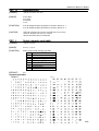
TH82
THERMAL PRINTER
REFERENCE MANUAL
Version 1.0 MAR.2004
CLOVER Electronics Co., Ltd.
1/1
CONTENTS
TH82 Series Reference Manual
INTRODUCTION ...............................................................................................................................3
FCC CLASS B ............................................................................................................................................................. 3
DECLARATION OF CONFORMITY ......................................................................................................................... 3
SAFETY STANDARDS (Power supply) ................................................................................................................. 3
ABOUT THIS MANUAL.............................................................................................................................................. 4
1
CHAPTER 1 SET UP.................................................................................................................5
1.1 UNPACKING ..................................................................................................................................................... 5
1.2 PRINTER COMPONENTS .............................................................................................................................. 5
1.3 ATTACHING INTERFACE CABLE TO THE PRINTER.............................................................................. 5
1.4 ATTACHING THE DRAWER, GROUND WIRE AND POWER SUPPLY........................................................... 6
1.4.1 THE DRAWER........................................................................................................................................... 6
1.4.2 GROUND WIRE ........................................................................................................................................ 6
1.4.3 POWER SUPPLY...................................................................................................................................... 6
1.5 SELF TEST ......................................................................................................................................................... 6
2
CHAPTER 2 OPERATION........................................................................................................7
2.1 POWER SWITCH ............................................................................................................................................. 7
2.2 CONTROL PANEL ........................................................................................................................................... 7
2.2.1 FEED........................................................................................................................................................... 7
2.2.2 ONLINE ...................................................................................................................................................... 7
2.3 PANEL LIGHTS ................................................................................................................................................ 7
2.3.1 POWER LED ............................................................................................................................................. 7
2.3.2 ONLINE LED ............................................................................................................................................. 7
2.3.3 ERROR LED .............................................................................................................................................. 7
3
CHAPTER 3 MAINTERNANCE & TROUBLESHOOTING .................................................8
3.1
3.2
3.3
3.4
INSTALLING OR REPLACING PAPER ROLL............................................................................................ 8
ADJUSTING THE PAPER NEAR END SENSOR....................................................................................... 8
PAPER JAM ...................................................................................................................................................... 9
TROUBLESHOOTING..................................................................................................................................... 9
4
CHAPTER 4 IMPORTANT SAFETY INFORMATION........................................................ 11
5
CHAPTER 5 SPECIFICATION...............................................................................................12
5.1 PRINTING SPECIFICATION......................................................................................................................... 12
5.2 PAPER SPECIFICATION .............................................................................................................................. 13
5.3 INTERFACE SPECIFICATION ..................................................................................................................... 13
5.3.1 RS-232 SERIAL INTERFACE SPECIFICATION ............................................................................... 13
5.3.2 SERIAL INTERFACE CONNECTION EXAMPLE ............................................................................. 13
5.3.3 POWER SUPPLY CONNECTOR ......................................................................................................... 14
5.3.4 DRAWER KICK-OUT CONNECTOR................................................................................................... 14
5.4 PACKAGE SPECIFICATION ........................................................................................................................ 15
6
CHAPTER 6 COMMANDS .....................................................................................................16
6.1
6.2
6.3
COMMAND TABLE........................................................................................................................................ 16
DESCRIPTION OF THE COMMANDS ....................................................................................................... 18
DETAILES........................................................................................................................................................ 18
APPENDIX A DIP SWITCH ...........................................................................................................67
SETTING & CHECKING THE DIP SWITCHES.................................................................................................... 67
APPENDIX B FIRMWARE DOWNLOAD ...................................................................................68
2/2
TH82 Series Reference Manual
INTRODUCTION
FCC CLASS B
This equipment generates and uses radio frequency energy and if not installed
and used properly, that is, in strict accordance with the manufacturer's
instructions, may cause interference to radio and television reception. It has
been type tested and found to comply with the limits for a Class B computing
device in accordance with the specifications in subpart J of part 15 of FCC
Rules, which are designed to provide reasonable protection against such
interference in a residential installation. However, there is no guarantee that
interference will not occur in a particular installation. If this equipment does
cause interference to radio or television reception, which can be determined by
turning the equipment off and on, the user is encouraged to try correct the
interference by one or more of the following measures:
--reorient the receiving antenna
--relocate the computer with respect to the receiver
--move the computer away from the receiver
--plug the computer into a different outlet so that computer and
receiver are no different branch circuits.
If necessary, the user should consult the dealer or an experienced
radio/television technician for additional suggestions. The user may find the
following booklet prepared by the Federal Communication Commission
helpful:
“How to Identify and Resolve Radio-TV Interference Problem.”
This booklet is available from the US Government Printing Office,
“Washington, D.C. 20402, Stock No. 004-000-00345-4.”
DECLARATION OF CONFORMITY
Declaration of Conformity
Manufacture’s name
Manufacture’s address
Product Name
Model Number(s)
: Clover Electronics Co., Ltd.
: 306-1, Akeno, Obata-Cho, Wataraigun, MIE, 519-0501, Japan
: Thermal Printer
: TH-82
Conform to the following standards
TH-82
: EMC EN50024
EN55022
EN61000-3-3
EN61000-3-2
SAFETY STANDARDS (Power supply)
UL, CUL, TÜV
3/3
TH82 Series Reference Manual
ABOUT THIS MANUAL
GETTING STARTED
CHAPTER 1 contains information on unpacking the printer and setting it up.
CHAPTER 2 contains information on using the printer.
CHAPTER 3 contains information of maintenance and troubleshooting.
CHAPTER 4 contains security information.
SPECIFICATION
CHAPTER 5 contains printers’ specification.
CHAPTER 6 contains character code tables and commands.
APPENDIX A contains information on setting and changing the DIP switches.
APPENDIX B tells how to download the firmware.
NOTE : This guide includes information about following models.
ANK characters with auto cutter
TH-82A
ANK characters without auto cutter TH-82AN
Japanese and Euro-American model: TH-82J
Above model without auto cutter:
TH-82JN
*Chinese and Euro-American model: TH-82C
Above model without auto cutter:
TH-82CN
Korean and Euro-American model: TH-82K
Above model without auto cutter:
TH-82KN
*Note Chinese model merchandising was not fixed under the influence of Chinese
domestic law as of Jan, 2004. For further information, please contact us.
SAFETY DEFINITIONS
In order to avoid hazards to a user or other persons and damage to the product, be sure to observe
the following instructions
For the safety of the personnel and the product, operate the equipment according to the instructions
in this user’s guide. The manufacturer will not be responsible for any problems or damage that
arises from improper use.
WARNING
: Warning may result in death or serious injury.
CAUTION
: Caution may result in injury or damage to property.
© 2000 Clover Electronics Co., Ltd. All rights reserved.
No part of this document may be reproduced without the expressed permission of Clover
Electronics Co., Ltd.
The material in this document is for informational purpose and is subject to change without notice.
Clover Electronics Co., Ltd. assumes no responsibility for errors or omissions in this document.
No liability is assumed for any damages resulting from the use of the information it contains.
4/4
TH82 Series Reference Manual
1 CHAPTER 1 SET UP
1.1 UNPACKING
Check for the following items in your box.
1
2
3
4
thermal printer
roll paper
AC adapter
AC cord
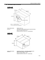
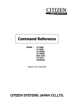
1.2 PRINTER COMPONENTS
PRINTER COVER
COVER OPEN KNOB
CONTROL PANEL
PAPER CUTTER COVER
POWER SWITCH
Before connecting any of the cables, please turn off the HOST device.
1.3 ATTACHING INTERFACE CABLE TO THE PRINTER
You need an appropriate interface cable. Refer to section 5.3.1 on page 13 for cable details.
1: Plug the cable into the interface connector located on the back of the printer, as indicated below.
2: Firmly tighten the screws on both sides of the connector.
3: Attach the other end of the cable to the HOST.
5/5
TH82 Series Reference Manual
1.4 ATTACHING THE DRAWER, GROUND WIRE AND POWER SUPPLY
DRAWER KICK CABLE
DC CABLE
1.4.1
GROUND WIRE
THE DRAWER
CAUTION : You need a drawer that fits the printer’s specification.
Do not connect a telephone line to the drawer kick-out connector.
Plug the drawer kick cable into the kick-out connector. If two drawers are used, use a Y-cable that
meets the specifications on page 14 to ensure that both drawers receive signals correctly.
1.4.2
GROUND WIRE
Use a ground wire that matches your printer. It is recommended to use a ground wire that is at least
the same length as the power cable. Connect the ground wire to the back of the printer with the
supplied screw as shown above.
1.4.3
POWER SUPPLY
CAUTION : Before connecting or disconnecting the power supply to the printer, make sure that the power supply is unplugged from the
power outlet and connect the power cord into the adapter.
1: Make sure that the adapter plug is unplugged from the power outlet.
2: Plug the DC cable into power connector with the flat side of the plug turned up.
When disconnecting the adapter, turn the printer off and the DC cable out by gripping the
plug. Do not pull it out by the cord.
CAUTION :
1.5 SELF TEST
Use the self test to check that your printer is operating properly. It checks the control circuits, printer
mechanisms, print quality, and displays the firmware version and DIP switch settings.
1 : Make sure that the printer cover is closed properly and turn the power off.
2 : While holding down the FEED button, turn the printer on and continue holding down the FEED
button until the self test starts.
3 : The self test will end automatically and detach the self test print out.
NOTE : Refer to CHAPTER 3, MAINTENANCE & TROUBLESHOOTING about how to install and
replace the paper roll.
6/6
TH82 Series Reference Manual
2 CHAPTER 2 OPERATION
Use the indicator’s lights to monitor the printing status.
2.1 POWER SWITCH
Turn the printer ON or OFF.
2.2 CONTROL PANEL
2.2.1
FEED
Press the FEED button to advance the paper by one line. Hold down the FEED button to advance
paper continuously.
2.2.2
ONLINE
Press the ONLINE button to put the printer online or offline. The green light indicates the printer is
online. Pressing the online button during printing will pause printing until the online button is
pressed again.
2.3 PANEL LIGHTS
2.3.1
POWER LED
This lights up whenever the printer is on.
2.3.2
ONLINE LED
This lights up when the printer is in online.
2.3.3
ERROR LED
This indicates an error. Refer to page 9, TROUBLESHOOTING about any action for ERROR
LED.
CONTROL PANEL
ONLINE
PANEL LIGHTS
CONTROL PANEL
FEED
7/7
TH82 Series Reference Manual
3 CHAPTER 3 MAINTERNANCE & TROUBLESHOOTING
3.1 INSTALLING OR REPLACING PAPER ROLL
CAUTION : make sure that paper rolls meets printer’s specification. Do not use paper rolls that have one end
glued to the core. This causes excessive load on the paper feed.
1 : Make sure that the printer is not printing or receiving data, and open the printer cover by pressing the
cover open knob. Unroll several inches of the paper as shown.
2 : Insert the paper roll as shown.
3 : Pull out several inches of paper and close the printer cover as shown.
Tear off the excess paper on the cutter edge.
3.2 ADJUSTING THE PAPER NEAR END SENSOR
A sensor detects when the paper roll is running out. Due to variation in the width of paper roll cores, it is
difficult to measure the exact length of the paper left on the roll when the detector is triggered. The factory
setting is based on a paper roll core with an outside diameter of 18mm and an inside diameter of 12mm. If you
use a paper roll with different widths, adjust the setting as described below.
1: Open the printer cover and remove the paper roll.
2: Loosen the adjusting screw and move the tab to fit the core of the paper roll.
3: Tighten the adjusting screw.
4: Replace the paper roll and close the printer cover.
8/8
TH82 Series Reference Manual
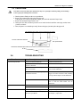
3.3 PAPER JAM
CAUTION : Do not touch the printer head because they are very hot after continuous printing. Do not attempt
to clear a paper jam until the printer cools down.
1 : Turn the printer off and press the cover open button.
2 : Remove the jammed paper and replace the paper roll.
If the printer cover can’t be opened after a paper jam, check the Automatic Paper Cutter.
1 : Remove the Automatic Paper Cutter Cover.
2 : Pull up the clear film, and slowly turn the screw inside clockwise until the cutter edge reaches home
position, see below.
3 : Now, the printer cover should open easily. Remove the paper jam and replace the paper roll.
The Automatic Paper Cutter moves towards the home position
Turn the inside screw clockwise.
Pull up the clear film
Remove the Automatic Paper Cutter Cover
3.4
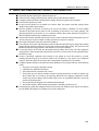
TROUBLESHOOTING
Error Contents
Can’t turn the printer ON
Causes/point to check
Is the Power Switch turned ON?
Solutions
Turn the Power Switch ON
Is the connector on the power adapter Connect the Connector firmly
properly connected?
Does the Printer reset when you turn the If it does, something is wrong with the Operation
Power Switch ON?
Panel. Call for SERVICE※
Does the LED on the Adapter light up when If it doesn’t, check the connection of the Power
connected to the wall?
Supply Cord. If the connection is OK, something
is wrong with the Adapter. Call for SERVICE※
Other
ON LINE Indicator doesn’t light Is the ERROR Indicator ON?
up
Press the ON LINE Button
ERROR Indicator is ON
Check if the printer is out of paper
Something may be wrong with the Power Switch
Parts or with the Main Board. Call for
SERVICE※
If it is, see “ERROR Indicator is ON
If ON LINE Indicator turns on, it’s normal
If paper is out, replace with a new roll
The Cover doesn’t open even if you press The Automatic Paper Cutter may be locked.
the Cover Open Button
See Chapter 7, “Paper Jam”.
9/9
TH82 Series Reference Manual
Error Contents
Check/points to check
ERROR Indicator is ON
The Printer Cover doesn’t close completely
Can’t print the self test
ONLINE Indicator is not ON
Printing causes the paper to feed
Solutions
Open the Cover by pressing the Cover Open
Button, and Close it again by pushing at center of
ERROR Indicator doesn’t light up ON LINE Indicator lights up after pushing Something is wrong with Paper Sensor on the
when out of paper. (The Printer the ON LINE Button
MAIN Board inside the Printer
Cover is closed)
Other
Something is wrong with the Operating Panel.
Call for SERVICE※
ERROR Indicator doesn’t light up ONLINE Indicator lights up and off after Something is wrong with Paper Sensor of the
pushing the ON LINE button.
MAIN Board inside the Printer
while the Printer Cover is open
Other
Something is wrong with the Operating Panel
See “ON LINE Indicator doesn’t light up
Something is wrong internally or with the Printer
Head Call for SERVICE※
Printing cannot be done by the Check print capability by running the If printing fails, see “Can’t Print”
commands from the HOST or Self-Test
peinting gabled.
Is the Connector of Interface firmly Seat the Connector firmly and tighten the screws
connected with screws?
Check the setting of DIP Switch
Refer APPENDIX A and set the switches
correctly, then power cycle the printer
Drawer Kick doesn’t work
Is the drawer kick connected properly?
Re-plug in the cable. You should hear or feel a
click if the proper connection is made.
Is the Y-cable connected reverse order?
Check the Y-cable and verify it is connected in
the correct order.
Other
Something may be wrong with the MAIN Board
inside the Printer. Call for SERVICE※
ERROR Indication and
Check the setting of DIP Switch
Refer to APPENDIX A. Turn the printer off,
ON LINE Indication flash
make any necessary changes, then turn the
on and off alternately
printer on.
※”SERVICE CALL” Do not attempt to repair problems requiring SERVICE CALL. It can be dangerous to your health
and or cause additional damage to the product. Entries requiring SERVICE CALL are hardware failures and require repair
by qualified service personnel.
10/10
TH82 Series Reference Manual
4 CHAPTER 4 IMPORTANT SAFETY INFORMATION
■
■
■
■
■
■
■
■
■
■
■
■
■
Read all the direction and keep this manual for future use.
Follow all of the warnings and instructions marked on the product and in this manual.
Unplug this product from the wall outlet before cleaning. Do not use liquid or aerosol cleaners.
Do not use this product near water.
Do not place this product on an unstable cart, stand or table. The product could fall, causing serious
damage to the product and bystanders.
Slots and openings on the back or bottom of the case are provided for ventilation. To ensure reliable
operation of the product and to protect it from overheating, do not block or cover these openings. The
openings should not be placed near or over a radiator or heater. This product should not be placed in a
built-in installation unless proper ventilation is provided.
This product should be operated from the type of power source indicated on the marking label. If you are
not sure of the type of power available, consult your dealer or local power company.
Do not place this product where the cord will be walked on.
If an extension cord is used with this product, make sure that the total of the ampere rating of the products
plugged into the extension cord does not exceed the extension cord ampere rating. Also, make sure that
the total of all products plugged into the wall outlet does not exceed 15 amperes.
Do not push objects of any kind into this product through cabinet slots as they may touch dangerous
voltage points or short out parts that could result in a risk of fire or electric shock. Do not spill liquid of any
kind on the product.
Except as specifically explained in this manual, do not attempt to service this product by yourself.
Opening and removing the covers that are marked “Do Not Remove” may expose you to dangerous
voltage or other risks. Refer all servicing in these compartments to qualified service personnel.
Unplug this product from the wall outlet and contact qualified service personnel after any of the following
events:
□ The power cord or plug is damaged or frayed.
□ Liquid has been spilled into the product.
□ The product has been exposed to rain or water.
□ The product does not operate normally when the operating instructions are followed. Adjust only
those controls that are covered by the operating instructions since improper adjustment of other
controls may result in damage and will often require service by a qualified technician to restore the
product to normal operation.
□ The product has been dropped or the cabinet has been damaged.
□ The product exhibits a distinct change in performance, indicating a need for service.
Keep the poly bag which this equipment came packed in away from children, and or dispose of it safely to
prevent children from putting it on. Putting it on can cause suffocation.
11/11
TH82 Series Reference Manual
5 CHAPTER 5 SPECIFICATION
5.1 PRINTING SPECIFICATION
TYPE
TH-82
TH-200, TH-200s
Model NO. of Printer Mechanism
LTPE347B-C576 ※1
LTPF347A-C576 ※1
Printing Method
Direct Line Thermal
Direct Line Thermal
Dot pitch
8 dot/mm
8 dot/mm
Printing Speed
75 mm per second (Max.)
210 mm per second (Max.)
Printing width
72 mm / 576 dots
72mm / 576 dots
Character structure
8 x 16 (font B)
12 x 24 (font A)
8 x 16 (font B)
12 x 24 (font A)
Printing Columns
69 columns/line
46 columns/line
69 columns/line
46 columns/line
Character Size
1.00 x 2.00
1.50 x 3.00
1.00 x 2.00
1.50 x 3.00
Fonts
US-ASCII, international characters
US-ASCII, Katakana, international characters
Japanese / Chinese (GB2312-80)
Japanese/Chinese(GB2312-80)
/ Korea (KS C 5601-1989) ※2
/ Korea (KS C 5601-1989) ※2
Interface
RS232C (serial)
RS232C (serial)
Input buffer
8K bytes
8k bytes
Command
ESC/POS compliant
ESC/POS compliant
Paper Width & Diameter
80mm(W) x 80mm Dia. Max.
80mm(W) x 80mm Dia. Max.
Thermal head life
100 Million Pulses / 100km or more
100 Million Pulses / 100 km or more
Cutting method ※3
ACUF324A
Partial cut(one point left uncut) ※3
ACUF324A
Partial cut(one point left uncut) ※3
Auto cutter life
500,000 cuts
500,000 cuts
Operating time of auto cutter
600msec max/cycle
600msec max/cycle
Operating temperature
0 °C ∼ 40 °C
0 °C ∼ 40 °C
Storage temperature
-20 °C ∼ 50 °C
-20 °C ∼ 50 °C
Humidity
80%
80%
Dimension
145mm(W) x 193.2mm(L) x 120.1mm(H)
145mm(W) x 193.2mm(L) x 120.1mm(H)
Transfer speed
Max 19.2kBps
Max 38.4kBps
Supply voltage in standby
24V DC
24V DC
Weight
1.1kg
1.1kg
Barcode Alignment
○
○
Kanji ※2
※1
※2
for
※3
Ivory or black
Ivory or black
Case color
Manufactured by SIIP&S Inc. (Former name: Seiko Instruments Inc.)
Japanese, Chinese and Korea Kanji ability is model specific. Refer to page 4, ABOUT THIS MANUAL or your dealer
more information on the different models and Kanji ability.
CAUTION: Paper must be fed 3 mm after cutting to prevent paper jam.
12/12
TH82 Series Reference Manual
5.2 PAPER SPECIFICATION
Paper Width:
Paper roll size:
Specified paper:
Paper roll spool diameter:
79.5±0.5mm(3.13±0.02”)
Roll diameter:
Maximum 80mm (3.15”)
Take-up paper roll width:
80 +0.5/-1.0mm (3.15+0.02/-0.04”)
Specified thermal roll paper:
NTP080-80
[Original paper: TF50KS-E2C Nippon Paper Industries Co., Ltd.]
Packaged roll paper:
[Original paper: PD160R-N (Oji Paper Mfg. Co., Ltd.)]
In Japan: Nakagawa Manufacturing Co., Ltd.
In U.S.A: Nakagawa Mfg. (U.S.A.) Inc.
In Europe: Nakagawa Mfg. (Europe) GmbH
In Southeast Asia: N.A.K. Mfg. (Malaysia) SDN BHD
*The following paper can be used instead of the paper above:
Original paper: HP220AB1 (Mitsubishi Paper Mills Ltd.)
Inside
12 mm (0.47”)
Outside 18 mm (0.71”)
NOTE: The end of the paper roll must be free to come off the spool when finished. It must not
be adhesively attached or attached in another semi-permanent manner.
5.3 INTERFACE SPECIFICATION
5.3.1
RS-232 SERIAL INTERFACE SPECIFICATION
Serial
Asynchronous
DTR/DSR or XON/XOFF control
MARK = -3 to -15V:
Logic “1”/OFF
SPACE = +3 to +15V:
Logic “0”/ON
Baud rate:
9600, 19200bps
Data word length:
7 or 8 bits
Parity Settings:
None, even, odd
Stop bits:
1 or more
Connector (printer side):
Female DSUB-25 pin connector
NOTE: *The data word length, baud length, and parity depend on the DIP switch settings. (Refer
to Appendix A DIP SWITCH SETTING.)
Data transmission:
Synchronization:
Handshaking:
Signal levels:
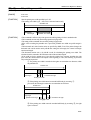
5.3.2
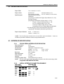
SERIAL INTERFACE CONNECTION EXAMPLE
HOST SIDE
(DTE ex.8251)
TXD
DSR
CTS
RTS
RXD
DTR
FG
SG
PRINTER SIDE
Pin No.
RXD
3
DTR
20
RTS
4
TXD
DSR
FG
SG
2
6
1
7
13/13
TH82 Series Reference Manual
5.3.3
POWER SUPPLY CONNECTOR
The connector is connected the printer to an external power source.
PIN
SIGNAL
1
+24V
2
GND
3
NC
SHELL
F.G
2
3
1
SHELL
CONNECTOR MODEL:
Printer side:
Hosiden TCS7960-532010 or equivalent
User side:
Hosiden TCP8927-631100 or equivalent
Hosiden TCP8927-531100 or equivalent
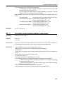
5.3.4
DRAWER KICK-OUT CONNECTOR
The pulse specified by ESC p or DLE DC4 is output to this connector. The HOST can confirm the
status of the input signal by using the DLE EOT, GS a, or GS r commands.
PIN
I/O
DESCIPTION
1
Frame ground
2
Output
Drawer kick-out drive signal 1
3
Input
Drawer open/close signal
4
Output
+24 V
5
Output
Drawer kick-out signal 2 ※
6
Signal ground
※Two drawers can be used with a Y-cable that meets the following specifications.
Pin 1: Frame ground ----------------------------------------------------Pin1
Pin 2: Drawer kick-out drive signal 1 -------------------------------- Pin2
Pin 3: Drawer open/close signal ---------------------------------------Pin3 Connector of Drawer No.1
Pin 4:+24V ----------------------------------------------------------------Pin4
Pin 5:Drawer kick-out signal 2 ------------------------Pin6
Pin 6: Signal ground Pin6 -------------------------------------Pin1
-----------------------Pin2
-----------------Pin3 Connector of Drawer No.2
------------Pin4
--------------------------------------Pin6
1
6
CONNECTIOR MODEL:
Printer side:
MOLEX52065-6615 or equivalent
Used side:
6-position 6-contact (RJ12 telephone jack)
14/14
TH82 Series Reference Manual
5.4 PACKAGE SPECIFICATION
OUTER CASE
Weight: 10.5 Kg
330 mm
560 mm
410 mm
Serial no.
Care mark on both sides
Model name
*Mark “C” should be stamped
below the model name for identification.
ENCLOSED GOODS:
DISPLAY
INNER CASE: 4pcs
CARE MARK, MODEL NAME: stamped in 2 parts (both sides)
SERIAL NO stickers attached: 4pcs
SEALING TAPE: OPP, clear color, “H” shaped taping
INNER CASE
Weight: 2.4kg
305 mm
265 mm
200 mm
Model name
Serial No.
ENCLOSED GOODS:
DISPLAY:
PRINTER, PAPER ROLL, GEATTING STARTED GUIDE
MODEL NAME: stamped in 2 parts (both sides)
SERIAL NO sticker attached: 1 part
SEALING TAPE: OPP, clear color, “I” shaped taping
15/15
TH82 Series Reference Manual
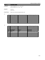
6 CHAPTER 6 COMMANDS
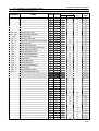
6.1 COMMAND TABLE
COMMAND
NAME
HT
FF
Horizontal tab
CR
Carriage return
Print in page mode and return to standard mode
LF
DLE NUL
Print and line feed
Clear
DLE ENQ
Real-time request to printer
DLE DC4
DLE EOT
Real-time pulse output
Real-time status transmission
CAN
ESC FF
ESC SP
ESC !
Cancel print data
Print data in page mode
Set the right space amount of the character
Select print mode
ESC
ESC
ESC
ESC
ESC
ESC
ESC
ESC
ESC
ESC
ESC
ESC
ESC
ESC
ESC
ESC
ESC
ESC
ESC
ESC
ESC
ESC
ESC
ESC
ESC
ESC
ESC
ESC
ESC
ESC
ESC
ESC
ESC
ESC
Set absolute print position
Specify/cancel download character set
Define download characters
Specify the bit-image mode
Turn underline mode on/off
Specify 1/6-inch line spacing
Set line spacing
Set logo pattern data
Set peripheral device
Cancel download characters
Initialize printer
Set horizontal tab positions
Turn emphasized mode on/off
Turn double-strike mode on/off
Print and feed paper
Select page mode
Select character font
Select an international character set
Select standard mode
Select print direction in page mode
Turn 90° clockwise rotation mode on/off
Set printing area in page mode
Set relative print position
Select justification
Select effective paper sensors
Select paper sensor to stop printing
Enable/disable panel switches
Print and feed n lines
Full cut
Select characters (ANK)
Partial cut
Print logo pattern
Generate pulse
Select character code table
$
%
&
*
2
3
4
=
?
@
D
E
G
J
L
M
R
S
T
V
W
╲
a
c3
c4
c5
d
i
k
m
o
p
t
TH-82 TH-200
○
○
○**
○
○
○
○
○
○
○
○
○**
○
○**
○
○
○
○
○
○**
○
○
○
○
○
○
○
○
○
○
○
○
○
○
○
○
○
○
○
○
○**
○
○
○
○
○
○
○**
○**
○
○
○
○
○
○
○
○
○
○
○
○
○
○
○
○
○
○
○
○
○
○
○
○
○
○
○
○
COMMAND
EXECUTING
SETTING
○
○
○
○
○
○
○
○
○
○
○
○
○
○
○
○
○
○
○
○
○
○
○
○
○
○
○
○
○
○
○
○
○
○
○
○
○
○
○
○
○
○
○
○
○
○
○
PAGE
MODE
MODE
○
○
○
○
○
○
○
○
○
○
○
○
○
○
○
○
○
○
○
○
○
○
○
○
○
○
○
○
○
○
○
○
○
○
○
○
○
○
○
○
○
○
○
○
○
○
○
○
○
○
○
(Line)
-
○
○
○
○
○
○
○
(Set)
○
○
(Line)
(Set)
○
○
○
○
○
○
○
○
(Set)
○
(Set)
(Line)
○
○
STANDARD
○
○
○
○
(Line)
○
○
○
○
○
○
-
○
○
16/16
TH82 Series Reference Manual
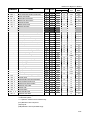
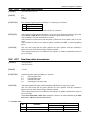
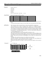
COMMAND
NAME
ESC ∼
FS g1
Transmit drawer status
Turn upside-down printing mode on/off
Specify print density
Write to NV user memory
FS g2
FS p
FS q
Read to NV user memory
Print NV bit image
Define NV bit image
ESC u
ESC {
FS r
FS !
Read NV bit image
Specify Kanji character print mode
FS &
Specify Kanji character mode
FS FS .
FS 2
FS C
FS S
FS W
FS k
GS !
GS $
GS *
GS ( A
GS /
GS :
GS B
GS E
GS H
GS I
GS
GS
GS
GS
L
P
V
W
GS ╲
GS ^
GS a
GS b
GS f
GS h
GS k
GS r
GS v 0
GS w
Turn underline mode on/off for Kanji character
Turn Kanji character mode off
Define download Kanji character
Select Kanji character code system
Set the space amount of Kanji character
Turn quadruple-size mode on/off for Kanji character
Select Kanji character font
Select character size
Set absolute vertical print position in page mode
Define download bit image
Execute test printing
Print download bit image
Start/end macro definition
Turn white/black reverse printing mode on/off
Select printing speed
Select printing position of HRI characters
Transmit printer ID
Set left margin
Specify basic calculate pitch
Cut paper
Set printing area width
Set relative vertical printing position in page mode
TH-82 TH-200
COMMAND
EXECUTING
SETTING
○
○
○
○
○
○
○
○
○
○***
○***
○***
○***
○***
○*
○***
○***
○***
○***
○***
○***
○***
○*
○***
○***
○
○**
○
○
○
○
○
○
○
○
○
○
○
○
○
○
○
○
○
○
○
○
○
○
○
○
○**
○
○**
○**
○**
○
○
Execute macro
Enable/disable Automatic Status Back
Turn smoothing mode on/off
Select font for HRI characters
○
Select bar code height
○
Print bar code
○
Transmit status
○
Print raster bit image
○
Select bar code width
* = Japanese model only
**=Influenced by GS P
*** = Japanese / Chinese / Korea characters only
○
○
○
○
○
○
○
○
○
○
○
○
○
○
(Line)
(Set)
○
○
○
○
○
○
○
○
○
○
○
○
○
○
○
○
○
○
○
○
○
○
○
○
○
○
○
○
○
○
○
○
○
○
○
○
○
○
○
○
○
MODE
(Line)
○
○
○
○
PAGE
MODE
○
○
○
○
STANDARD
-
-
○
-
○
○
○
○
○
○
○
○
○
○
○
○
○
○
(PBE)
○
○
○
○
○
○
○
○
○
○
○
(Line)
(Set)
○
○
○
(Line)
(Line)
-
○
○
○
○
○
(PBE)
○
(Line)
○
-
(Set)
○
○
○
○
○
○
○
○
-
○
(Line) Effective in case of top of line
(Set) Only set
(PBE) Effective in case of print buffer empty
17/17
TH82 Series Reference Manual
6.2 DESCRIPTION OF THE COMMANDS
The name of the command.
The code sequence. ASCII indicates ASCII equivalents. HEX indicates the
hexadecimal equivalents. < >H represents hexadecimal number, < > represents
decimal number and [ ]k represents a repeat count of k-times.
[RANGE]
Describes an argument value for the command.
[FUNCTION] Describes the function of the command.
[CAUTION]
Describes a caution as required.
[DEFAULT]
Describes an initial value for the command as required.
NAME
[FORMAT]
6.3 DETAILES
HT
Horizontal Tab
[FORMAT]
<09>H
[FUNCTION]
Moves the print start position to the next horizontal tab.
[CAUTION]
*The default setting is every 8 characters, (12 x 24).
*This command is ignored unless the next horizontal tab position has been set.
*Horizontal tab positions are set with ESC D.
FF
Print in page mode and return to standard mode
[FORMAT]
<0C>H
[FUNCTION]
Prints the data in the printable area collectively and return to the standard mode.
[DETAILES]
*The data is deleted after being printed.
*The printing area is reset to the default setting.
*This command does not cut the paper.
*After printing, the printing position is set to the beginning of the line.
*This command is enabled only in page mode.
CR
Carriage Return
[FORMAT]
<0D>H
This command is invalid.
[FUNCTION]
*This command prints the data in the print buffer and feeds one line.
*This command begins a line feed if the data has not been printed or has been all space data.
[CAUTION]
*This function can be disabled by DIP switch setting.
LF
Print and line feed
[FORMAT]
<0A>H
[FUNCTION]
*Prints the data in the print buffer and feeds one line.
*This command begins a line feed if the data has not been printed or has been all space data.
[CAUTION]
*After finished prinitng, the next starting position for printing is the biginning of the line.
*The default setting for the amount of linefeed is 4.125mm (33 dots).
18/18
TH82 Series Reference Manual
DLE NUL
Clear
[FORMAT]
<10>H<00>H
[FUNCTION]
*DLE NUL clears the data in the print buffer.
*This command clears part of the printer configuration.
DLE ENQ
Real-time request to printer
[FORMAT]
<10>H<05>H<n>
[RANGE]
1≦n≦2H
[FUNCTION]
DLE ENQ responds to a request in real time from the HOST, specified by n.
n=1:After removing a cause of the error, the printing restarts from the beginning of the line where
the error occurred.
n=2:The printer can recover from an error after clearing the receive and print buffers.
[DETAILES]
*This command is effective even when the printer is disabled with ESC = (selected peripheral
device).
*This command is effective only when an automatic cutter error occurs.
*This command is executed when the data is received.
*This command is executed even when the printer is off-line, the receive buffer is full, or an error
occurs.
[CAUTION]
*The user must notify that the printer performs the same operation with this command if
printer receives the same character strings with this command.
EXAMPLE
d1=<10>H, d2=<05>H, d3=<01>H in ESC * m n L nH [d] k.
This command is invalid.
*This command must not be used within the data sequence of another command that consists of
two or more bytes.
EXAMPLE
It must be noted that the code <10>H for DLE ENQ 2 is processed as the code for ESC 3
<10>H if DLE ENQ 2 interrupts before n received, on the transmission of ESC 3n from the
HOST to the printer.
19/19
TH82 Series Reference Manual
DLE DC4
Real-time pulse output
[FORMAT]
<10>H<14>H<n><m><t>
[RANGE]
n=1
m=0,1
1≦t≦8H
[FUNCTION]
This command outputs the pulse specified by t to connector pin m as follows.
m
Connector pin
0
Plug 1
1
Plug 2
The pulse ON time is t x100msec. and the OFF time is t x100msec..
[DETAILES]
*This command is ignored when the printer is in an error status while this command is processed.
*When ESC p or DEL DC4 is executed, this command is ignored and no pulse is sent.
*This command is executed when the data is received.
*This command is executed even when the printer is off-line, the receive buffer is full, or an error
occurs.
*This command is effective even when the printer is disabled with ESC = (selected peripheral
device).
[CAUTION]
*The user must notify that the printer performs the same operation with this command if
printer receives the same character strings with this command
*This command must not be used within the data sequence of another command that consists of
two or more bytes.
DLE EOT
Real-time status transmission
[FORMAT]
<10>H<04>H<n>
<1D>H<04>H<n>
[RANGE]
1≦n≦4H
[FUNCTION]
Transmits the printer status specified by n in real-time.
n=1
Transmit printer status
n=2
Transmit offline status
n=3
Transmit error status
n=4
Transmit paper roll sensor status
[CAUTION]
*The printer transmits the status without confirming if the HOST is ready to receive data.
*The user must notify that the printer performs the same operation with this command if
printer receives the same character strings with this command
*This command must not be used within the data sequence of another command that consists of
two or more bytes.
*When Auto Status Back (ASB), GS a command, is effective, the status transmitted by the DLE
EOT and the ASB status should be differentiated.
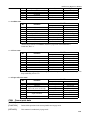
n = 1: Printer status
BIT
Function
0
1
Not used
Not used
VALUE
0
Fixed to off
-
1
Fixed to off
20/20
TH82 Series Reference Manual
2
3
4
5
6
7
Drawer open/close signal(connector pin 3)
Off/On
Not used
Undefined
Undefined
Not used
Low
Online
-
High
Offline
Fixed to off
Fixed to off
-
n = 2: Offline status
VALUE
0
1
0
Not used
Fixed to off
1
Not used
Fixed to off
2
Printer cover
Cover is closed
Cover is open
3
Paper FEED button
Not feeding
Under feeding
4
Not used
Fixed to off
5
Paper-end stop
No stop
stop
6
Error
No error
Error
7
Not used
Fixed to off
Bit 5: Printing stops when the paper end sensor detects paper end or the paper near end sensor
(TH80s only) is turned on with ESC C4. (Refer to page 34 for more information.)
At this time, Bit 5 = 1.
BIT
Function
BIT
Function
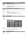
n = 3: Error status
VALUE
0
1
0
Not used
Fixed to off
1
Not used
Fixed to off
2
Motor slip
No error
Error
3
Autocutter
No error
Error
4
Not used
Fixed to off
5
Unrecoverble error
No error
Error
6
Auto recoverble error
No error
Error
7
Not used
Fixed to off
Bit 6: When printing is stopped due to high print head temparature until the print head temparature
drops sufficiently, bit 6 b is on.
n = 4: Paper roll sensor status
BIT
Function
0
1
2
3
4
5
6
7
Not used
Not used
Paper roll near-end sensor
(Near-end sensor model only)
Not used
Paper roll sensor
Not used
VALUE
0
Fixed to off
Adequate
Adequate
Present
Present
Fixed to off
1
Fixed to off
Near-end
Near-end
Fixed to off
End
End
-
CAN Cancel print data
[FORMAT]
<18>H
[FUNCTION]
Deletes all the print data in the current printable area in page mode.
[DETAILES]
This command is enabled only in page mode.
21/21
TH82 Series Reference Manual
ESC FF
Print data in page mode
[FORMAT]
<1B>H<0C>H
[FUNCTION]
Prints all buffered data in the printing area collectively in page mode.
[DETAILES]
*This command is enabled only in page mode.
*After printing, the printer keeps the buffered data, setting values for ESC T and ESC W, and the
position for buffering character data.
ESC SP
Set the right space amount of the character
[FORMAT]
<1B>H<20>H<n>
[RANGE]
0≦n≦255
[FUNCTION]
Sets the character spacing for the right space amount of the character to [n x horizontal or vertical
motion units].
[CAUTION]
*This command does not affect setting Kanji characters.
*The right space amount in double wide mode is twice the set volume.
*This command can set value indepently in each mode of standard and page modes.
[DEFAULT]
n=1
ESC !
Select print mode
[FORMAT]
<1B>H<21>H<n>
[RANGE]
0≦n≦FFH
[FUNCTION]
*Selects print mode collectively.
*Selects print mode using n as follows.
BIT
Function
0
1
2
3
4
5
6
7
Character font
Character font
Undefined
Emphasizing
Double-height
Double-width
Undefined
Underline
VALUE
0
Font A
(Depend on bit 0)
1
Font B
Font B
Cancelled
Cancelled
Cancelled
Selected
Selected
Selected
Cancelled
Selected
[DEFAULT]
n=0
[CAUTAION]
*Specification with double-height and width, and underline are invalid to Kanji.
*Character font can be changed at the beginning of a line only.
ESC $
Set absolute print position
[FORMAT]
<1B>H<24>H<n1><n2>
[RANGE]
0≦n1≦FFH
0≦n2≦FFH
22/22
TH82 Series Reference Manual
[CAUTION]
Sets the distance from the beginning of the line to the position at which subsequent characters
should be printed. The distance from the beginning of the line to the print position is (nl + n2x256) x
(vertical or horizontal motion unit).
Setting outside the printable area are ignored.
ESC %
Specify/cancel download character set
[FORMAT]
<1B>H<25>H<n>
[RANGE]
0≦n≦1
[FUNCTION]
n=0
n=1
[DEFAULT]
n=0
ESC &
Define download characters
[FORMAT]
<1B>H<26>H<s><c1><c2>[x1 d1...dn]...[xk d1...dn]
[RANGE]
s=2, 3
[FUNCTION]
Internal character set is specified.
Download character set is specified.
20H≦c1≦FEH
20H≦c2≦FEH
x=12
x=8
0≦d≦FFH
[FUNCTION]
The number of bytes in the vertical direction.
(2: font B, 3: font A)
The beginning character for the definition.
The final code for the definition.
The number of dots in the horizontal direction when font A is selected.
The number of dots in the horizontal direction when font B is selected.
The dot data for the character.
Defines download characters.
12 x dot
MSB
D1
D4
D7
――――――――
LSB
MSB
D2
D5
D8
――――――――
LSB
MSB
D3
D6
D9
――――――――
LSB
*When font A is selected.
[CAUTION]
*Font A and font B cannot be defined simultaneously.
ESC *
Specify the bit-image mode
[FORMAT]
<1B>H<2A>H<m><n1><n2>[d1...dk]
[RANGE]
m=0、1、32、33
0≦n1≦FFH
Mode
Low 8 bits of the number of printing dot.
23/23
TH82 Series Reference Manual
0≦n2≦1
High 8 bits of the number of printing dot.
Bit image data
0≦d≦FFH
[FUNCTION]
Prints data following the bit image modes specified by m
m
Mode
0
1
32
33
8-dot single-density
Vertical direction
Vertical direction
Horizontal direction
No. of dots
Dot density
Dot density
8
8
24
24
67DPI
67DPI
200DPI
200DPI
100DPI
200DPI
100DPI
200DPI
8-dot double-density
24-dot single-density
24-dot double-density
No. of data
n1 + n2 x 256
n1 + n2 x 256
(n1+n2x256)x3
(n1+n2x256)x3
n1+n2x256 dot
MSB
D1
D2
D3
――――――――
LSB
8-dot bit image (8-dot single-density is extended double to the horizontal direction.)
(n1+n2x256)x3 dot
MSB
D1
D4
D7
――――――――
LSB
MSB
D2
D5
D8
――――――――
LSB
MSB
D3
D6
D9
――――――――
LSB
24-dot bit image (24-dot single-density is extended double to the horizontal direction.)
ESC -
Turn underline mode on/off
[FORMAT]
<1B>H<2D>H<n>
[RANGE]
0≦n≦2、48≦n≦50
[FUNCTION]
Turns underline mode on or off.
24/24
TH82 Series Reference Manual
n
0,48
1,49
2,50
[CAUTION]
Function
Turns off underline mode
Turns on underline mode of 1-dot thick
Turns on underline mode of 2-dot thick
*An underline is attached to the full character width including right side character spacing, but not
attached to the space set by HT and 90o clockwise rotated character by ESC V.
*When underline mode is turned off by setting the value of n to 0 or 48, the following data is not
underlined and the underline thickness set before the mode is turned off is kept. The default
underline thickness is 1 dot.
*Changing the character size does not affect the current underline thickness.
*This command does not affect Kanji printing.
Ref. FS -, Turn underline mode on/off for Kanji character.
*Underline mode can also be turned on or off by using ESC !, but note that the last received
command is effective. When underline mode is turned off by using ESC – after turned on by ESC !,
underline mode by ESC ! is turned off.
[DEFAULT]
n=0
ESC 2
Specify 1/6-inch line spacing
[FORMAT]
<1B>H<32>H
[FUNCTION]
The line spacing per line is specified by 1/6 inch.
[DEFAULT]
*The default setting is 4.125mm (33 dots).
ESC 3
Set line spacing
[FORMAT]
<1B>H<33>H<n>
[RANGE]
0≦n≦255
[FUNCTION]
*Sets the line spacing to [n x vertical or horizontal motion unit].
*The line spacing can be set independently in standard mode and in page mode.
[DEFAULT]
Line spacing equivalent to 1/6 inch.
ESC 4
Set logo pattern data
[FORMAT]
<1B>H<34>H<n1><n2> data1 – data720
[RANGE]
1≦n1≦127
1≦n2≦127
[FUNCTION]
Sets logo pattern data by this command.
This command is invalid.
25/25
TH82 Series Reference Manual
*n1 is the total block number of logo pattern which should be set.
[CAUTION]
Block number 1(n2)
Total bock number(n1)
Block number N-1
Block number N
・n2is the block number which should be set.
・data1 – data720 sets logo pattern data.
MSB
1
LSB
8 9
d1
d2
16 17
d71
713 720
d72
1dot line
d72
d74
d143
d144
2dot line
d713
d714
d719
d720
10dot line
ESC =
Set peripheral device
[FORMAT]
<1B>H<3D>H<n>
[RANGE]
0≦n≦255
[FUNCTION]
n=<******0>B:printer disabled, ignores all data.
n=<******1>B:Printer enabled.
ESC ?
Cancel download characters
[FORMAT]
<1B>H<3F>H<n>
[RANGE]
32≦n≦126
[FUNCTION]
Cancels download characters.
[CAUTION]
*n is the character code which cancels the defined pattern. After the download characters are
canceled, the pattern for the internal character is printed.
*This command deletes the pattern defined for the specified code in the font selected by ESC !.
*If a download character has not been defined for the specified character code, the printer ignores
this command.
*If n is out of the range, the printer ignores this command.
ESC @
Initialize printer
[FORMAT]
<1B>H<40>H
[RANGE]
32≦d≦126
[FUNCTION]
Clears the data in the print buffer and initializes the printer mode which set by the software.
26/26
TH82 Series Reference Manual
[CAUTION]
*The DIP switch settings are not checked again.
*The data in the receive buffer is not cleared.
*The macro definition is not cleared.
*The NV bit image data is not cleared.
ESC D
Set horizontal tab positions
[FORMAT]
<1B>H<44>H[d1...dk]<00>
[RANGE]
0≦d≦FFH 1≦k≦32
[FUNCTION]
Sets horizontal tab positions.
[CAUTION]
*d specifies the column number.
*k indicates the total number of horizontal tab position
*The horizontal tab position is set at position where it is [character width x the column number]
from the beginning of the line.
*The horizontal tab position does not change even if the character width is altered after setting the
horizontal tab position.
*Set d in ascending order.
*ESC D 00h cancels all horizontal tab positions.
*Data exceeding 32 tab positions is ignored.
[DEFAULT]
Intervals of 8 characters.
ESC E
Turn emphasized mode on/off
[FORMAT]
<1B>H<45>H<n>
[RANGE]
0≦n≦255
[FUNCTION]
Turns emphasized mode on or off.
n=<*******0>B
Emphasized mode is turned off.
n=<*******1>B
Emphasized mode is turned on.
[DETAILES]
*n is valid only for the lowest bit.
*Emphasized mode can be turned on and off by ESC ! as well but the last received command is
effective.
[DEFAULT]
n=0 (emphasized mode off)
ESC G
Turn double-strike mode on/off
[FORMAT]
<1B>H<47>H<n>
[RANGE]
0≦n≦255
[FUNCTION]
Turns double-strike mode on or off.
27/27
TH82 Series Reference Manual
n=<*******0>B
n=<*******1>B
Double-strike mode is turned off.
Double-strike mode is turned on.
[DETAILES]
*n is valid only for the lowest bit.
*Printer output is all the same with emphasized mode.
[DEFAULT]
n=0 (double-strike mode off)
ESC J
Print and feed paper
[FORMAT]
<1B>H<4A>H<n>
[RANGE]
0≦n≦255
[FUNCTION]
Prints the data in the print buffer and feeds the paper [n x vertical or horizontal motion unit].
ESC L
Select page mode
[FORMAT]
<1B>H<4C>H
[FUNCTION]
Switches from standard mode to page mode.
[DETAILES]
*This command is enabled only when processed at the beginning of a line in standard mode.
*This command is ignored in page mode.
*The printer returns to standard mode after printing by FF is completed or by using ESC S.
*This command sets the position where data is buffered to the position specified by ESC T within
the printing area defined by ESC W.
*This command switches the setting for the following commands which have each value
independently in standard mode and page mode to those for page mode.
□Set right-side character spacing: ESC SP, FS S
□Set default line spacing: ESC 2、ESC 3
*Only setting is possible for the following commands in page mode.
① ESC V
Turn 90°clockwise rotation mode on/off.
② ESC a
Select justification.
③ ESC {
Turn upside-down printing mode on/off.
④ GS L
Set left margin.
⑤ GS W
Set printing area width
*The following command is not available in page mode.
① FS p
Print NV bit image.
② FS q
Define NV bit image.
③ FS g1
Write to NV user memory.
④ GS v 0
Print raster bit image.
*The printer returns to standard mode when ESC @ is used.
ESC M
Select character font
[FORMAT]
<1B>H<4D>H<n>
[RANGE]
n=0,1,48,49
[FUNCTION]
Selects character fonts.
n
Function
0,48 Font A (12 x 24) selected.
28/28
TH82 Series Reference Manual
[DETAILES]
ESC R
1,49 Font B (8x16) selected.
The ESC ! command can also select the character fonts but the setting of the last received
command is effective.
Select an international character set
[FORMAT]
<1B>H<52>H<n>
[RANGE]
0≦n≦13
[FUNCTION]
*Selects an international character set.
*The code table is as follows.
23
ESC
S
Sel
ect
standard
mode
n=0
n=1
n=2
n=3
n=4
n=5
n=6
n=7
n=8
n=9
n=10
n=11
n=12
n=13
[FORMAT]
<1B>H<53>H
24
40
5B
5C
5D
5E
60
7B
7C
7D
7E
(U.S.A)
(FRANCE)
(GERMANY)
(U.K)
(DENMARK)
(SWEDEN)
(ITALY)
(SPAIN)
(JAPAN)
(NORWAY)
(DENMARK2)
(SPAIN2)
(LATIN)
(KOREA)
[FUNCTION]
Switches from page mode to standard mode.
[DETAILES]
*This command is effective only in page mode.
*Data buffered in page mode are cleared.
*This command sets the print position to the beginning of the next line after executed.
*The printing area set by ESC W are initialized.
*This command switches the setting for the following commands which have each value
independently in standard mode and page mode to those for standard mode.
①Set right-side character spacing:
ESC SP、FS S
②Select default line spacing:
ESC 2、ESC 3
*Only setting is possible for the following commands in standard mode.
① ESC W
Set printing area in page mode.
② EST T
Select printing direction in page mode.
*The following commands are ignored in standard mode.
① GS $
Set absolute vertical print position in page mode.
② GS ╲
Set relative vertical print position in page mode.
*Standard mode is selected automatically when power is turned on or ESC @ is used.
29/29
TH82 Series Reference Manual
ESC T
Select print direction in page mode
[FORMAT]
<1B>H<54>H<n>
[RANGE]
0≦n≦3 、48≦n≦51
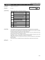
[FUNCTION]
Selects the print direction and start position in page mode.
Print direction
Starting position
n
0,48 Left to right
Upper left (A in
the right figure)
2,50
3,51
Bottom to top
Lower left (B in
the right figure)
Right to left
Lower right (C in
the right figure)
Top to bottom Upper right (D in
the right figure)
Print area
Forward
1,49
[DETAILES]
*When the command is selected in standard mode, the printer executes only internal flag operation.
This command does not affect printing in standard mode.
*This command sets the position where data is buffered within the printing area set by ESC W.
* Horizontal or vertical motion units (x or y) of the following commands differ depending on the
starting position of the printing area.
①If the starting position is the upper left or lower right, data is buffered in the direction
perpendicular to the paper feed direction.
Commands using horizontal motion units (x) : ESC SP, ESC $, ESC ╲.
Commands using vertical motion units (y) : ESC 3, ESC J, GS $, GS ╲.
②If the starting position is the upper right or lower left, data is buffered in the paper feed
direction.
Commands using horizontal motion units (x) : ESC 3, ESC J, GS $, GS ╲.
Commands using vertical motion units (y) : ESC SP, ESC $, ESC ╲.
[DEFAULT]
n=0
ESC
Turn 90°clockwise rotation mode on/off
V
[FORMAT]
<1B>H<56>H<n>
[RANGE]
0≦n≦1H , 30H≦n≦31H
[FUNCTION]
Turns 90°clockwise rotation mode on/off.
*n=0,30H Turns off
*n=1,31H Turns on
[CAUTION]
Double-width and double-height commands in 90°rotation mode enlarge characters in the
opposite directions from double-height and double-width commands in normal mode.
[DEFAULT]
n=0
30/30
TH82 Series Reference Manual
ESC W
Set printing area in page mode
[FORMAT]
<1B>H<57>H<xL><xH><yL><yH><dxL><dxH><dyL><dyH>
[RANGE]
0≦xL、xH、yL、yH、dxL、dxH、dyL、dyH≦255
ATTN: Except dxL=dxH=0 or dyL=dyH=0
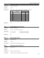
[FUNCTION]
Sets printing area and position.
Horizontal starting position =[(xL + xH x 256) x horizontal motion unit]
Vertical starting position =[(yL + yH x 256) x vertical motion unit]
Printing area width =[(dxL + dxH x 256) x horizontal motion unit]
Printing area height =[(dyL + dyH x 256) x vertical motion unit]
[DETAILES]
*When the command is selected in standard mode, the printer executes only internal flag operation.
This command does not affect printing in standard mode.
*If the horizontal or vertical starting position is out of the printable area, the printer stops command
processing and processes the following data as normal data.
*If the printing area width or height is 0, the printer stops command processing and processes the
following data as normal data.
*The position where data is buffered is the position specified by ESC T within the printing area.
*If (horizontal starting position + printing area width) exceeds the printable area, the printing area
width is set to (horizontal printable area – horizontal starting position.)
*If (vertical starting position + printing area height) exceeds the printable area, the printing area
height is set to (vertical printable area – vertical starting position).
*The horizontal and vertical motion unit are set by GS P. Changing the horizontal or vertical
motion unit after set printing area, does not affect the current printing area.
* The calculated result is truncated to the minimum value of the mechanical pitch.
*Use the horizontal motion unit (x) for setting the horizontal starting position and printing area
width and also use the vertical motion unit (y) for setting the vertical starting position and printing
area height.
*The printing area is as follows if the horizontal starting position is defined as X, vertical starting
position as Y, printing area width as Dx and printing area height as Dy.
Paper
(X、Y)
Dy
Printing area
Forward
Dx
(X+Dx-1、Y+Dy-1)
*The printable area for this printer is approximately72.2mm {576 dot (519/180”)} in the horizontal
direction and approximately 104mm {831 dot (1496/360”)} in the vertical direction.
[DEFAULT]
xL=xH=yL=yH=0
dxL+dxH×256=519 dyL+dyH×256=1496
31/31
TH82 Series Reference Manual
ESC ╲
Select relative print position
[FORMAT]
<1B>H<5C>H<n1><n2>
[RANGE]
0≦n1≦FFH
0≦n2≦FFH
[FUNCTION]
*Sets the print starting position based on the current position.
*[(n1+n2×256)× horizontal or vertical motion unit].
[CAUTION]
*Setting that exceeds the printable area is ignored.
*When the printable area moves from current position to the right, specify positive direction and to
the left, specify negative direction.
(When pitch N moves to the left)
65536-N = n1+n2x256
ESC a
Select justification
[FORMAT]
<1B>H<61>H<n>
[RANGE]
0≦n≦2, 48≦n≦50
[FUNCTION]
Aligns all the printed data within one line to the specified position.
n = 0,48
Left justification
n = 1,49
Centering
n = 2,50
Right justification
[CAUTION]
*This command is enabled only when processed at the beginning of a line.
[DEFAULT]
n=0
32/32
TH82 Series Reference Manual
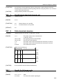
ESC c 3
Select paper sensor to output paper end signals
[FORMAT]
<1B>H<63>H<33>H<n>
[RANGE]
0≦n≦255
[FUNCTION]
Selects the paper sensor to output paper end signals.
BIT FUNCTION
HEX.
0
This command is invalid.
Paper roll near end sensor disabled
00
Paper roll near end sensor enabled.
01
Paper roll near end sensor disabled
00
Paper roll near end sensor enabled.
02
Paper roll end sensor disabled
00
Paper roll end sensor enabled.
04
Paper roll end sensor disabled
00
Paper roll end sensor enabled.
08
4
Undefined
-
5
Undefined
-
6
Undefined
-
7
Undefined
-
1
2
3
*Bit 0 and 1 are valid only on near-end sensor model.
[CAUTION]
*This command is effective only with a parallel interface and is ignored with a serial interface.
*It is possible to select multiple sensors to output signals. If multiple sensors are effective, the paper
end signal is output when any of the sensors detects a paper end.
*The paper end signal switching may be delayed depending on the receive buffer state because
sensor is switched when this command is executed.
*If either bit 0 or bit 1 is on, the paper roll near-end sensor is selected as the paper sensor which
outputs paper end signals. This function is valid only on model TH-80s.
*If either bit 2 or bit 3 is on, the paper roll end sensor is selected as the paper sensor which outputs
paper end signals.
*When all the sensors are disabled, the paper end signal always outputs a paper present status.
[DEFAULT]
n=1
33/33
TH82 Series Reference Manual
ESC c 4
Select paper sensor to stop printing (Near-end sensor model only)
[FORMAT]
<1B>H<63>H<34>H<n>
[RANGE]
0≦n≦255
[FUNCTION]
Selects the paper sensor to stop printing when a paper near end is detected.
VALUE
BIT
FUNCTION
0
1
0
Paper roll near end sensor.
Disabled.
Enabled.
1
Undefined.
2
Undefined.
3
Undefined.
4
Undefined.
5
Undefined.
6
Undefined.
Undefined.
7
*This function is valid only on near-end sensor model .
[DEFAULT]
n=0
ESC c 5
Enable/disable panel switches
[FORMAT]
<1B>H<63>H<35>H<n>
[RANGE]
0≦n≦255
[FUNCTION]
n=<*******0>B
n=<*******1>B
[DEFAULT]
n=0
ESC d
Print and feed n lines
[FORMAT]
<1B>H<64>H<n>
[RANGE]
1≦n≦255
[FUNCTION]
Prints the data in the print buffer and feeds n lines.
ESC i
Full cut (one point left uncut)
[FORMAT]
<1B>H<69>H
[RANGE]
-
[FUNCTION]
Sets full cut. (one point left uncut)
[CAUTION]
*Paper must be fed 3 mm after printing to prevent paper jam.
n is valid only in the lowest bit.
The panel switches are enabled.
The panel switches are disabled
34/34
TH82 Series Reference Manual
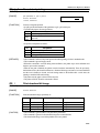
ESC k
Select characters (ANK)
[FORMAT]
<1B>H<6B>H<n>
[RANGE]
0≦n≦1
[FUNCTION]
[CAUTION]
Select ANK characters specified by n.
VALUE
FUNCTION
0
1
Select characters
Mintyo
Gothic
Undefined
Undefined
Undefined
Undefined
Undefined
Undefined
Undefined
This command ignores in the model with one of above characters
ESC m
Partial cut (one point left cut)
[FORMAT]
<1B>H<69>H
[RANGE]
-
[FUNCTION]
Sets Partial cut.
[CAUTION]
* Paper must be fed 3 mm after printing to prevent paper jam.
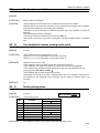
ESC o
Print logo pattern
[FORMAT]
<1B>H<6F>H<n1><n2>
[RANGE]
1≦n1≦127
BIT
0
1
2
3
4
5
6
7
This command is invalid.
1≦n2≦127
[FUNCTION]
This command prints logo pattern.
[CAUTION]
*n1 specifies starting block of the logo pattern.
*n2 specifies stopping block of the logo pattern.
Block number 1
Starting block (n1)
Block number N-1
Block number N
Stopping block (n2)
*This command is enabled only when processed at the beginning of a line.
35/35
TH82 Series Reference Manual
ESC p
Generate pulse
[FORMAT]
<1B>H<70>H<m><n1><n2>
[RANGE]
m=0,1,48,49
0≦n1≦FFH
0≦n2≦FFH
n1≦n2
[FUNCTION]
m=0,48: Outputs the pulse specified by n1 and n2 to drawer no. 1.
m=1,49: Outputs the pulse specified by n1 and n2 to drawer no. 2.
[CAUTION]
*The pulse ON time is n1 x 2 msec. and OFF time is n2 x 2 msec.
*If n2<n1, the pulse OFF time is n1 x 2msec.
*Do not activate the drawer continuously.
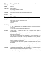
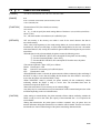
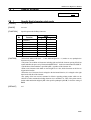
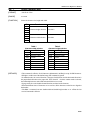
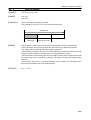
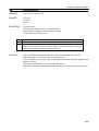
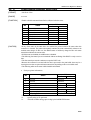
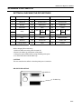
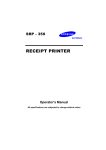
ESC t
Select character code table
[FORMAT]
<1B>H<74>H<n>
[RANGE]
0≦n≦5、n=18,19
[FUNCTION]
Selects a page n of the character code table.
n
PAGE
0
PC437(USA:Standard Europe)
1
Kana
2
PC850(Multilingual)
3
PC860(Portuguese)
4
PC863(Canadian-French)
5
PC865(Nordic)
18
PC852(Latin 2)
19
PC858
[DEFAULT]
n=0
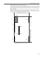
Character code table
36/36
TH82 Series Reference Manual
37/37
TH82 Series Reference Manual
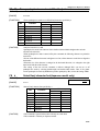
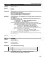
ESC u
Transmit drawer status
[FORMAT]
<1B>H<75>H<n>
[RANGE]
n=0、48
[FUNCTION]
Transmits the status of drawer sensor.
Status bit 0 = 0: plug 1 Closed
Bit 0 = 1: plug 1 Open
Bit 1 = 0: plug 2 Closed
Bit 1 = 1: plug 2 Open
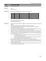
ESC {
Turn upside-down printing mode on/off
[FORMAT]
<1B>H<7B>H<n>
[RANGE]
0≦n≦FFH
[FUNCTION]
Turns upside-down printing mode on or off.
*n = Turn off even number
*n = Turn on odd number.
[CAUTION]
*This command is enabled only when processed at the beginning of a line.
[DEFAULT]
n=0
This command is invalid.
38/38
TH82 Series Reference Manual
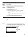
ESC ∼
Select print density
[FORMAT]
<1B>H<7E>H<m><n>
[RANGE]
m=0, 0≦n≦7
[FUNCTION]
Selects print density.
Sets print density specified by n as follows.
n=0
Lightest
n=7
Deepest
[CAUTION]
This command is enabled only when processed at the beginning of a line.
[DEFAULT]
n=3
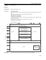
FS g 1
Write to NV user memory
[FORMAT]
<1C>H<67>H<31>H<m><a1><a2><a3><a4><nL><nH>[d1...dk]
[RANGE]
m=0
[FUNCTION]
Writes data to NV(Non-volatile) user memory.
*m is set to 0.
*a1、a2、a3 and a4 specify the stored starting address of the data to (a1+(a2x256)+(a3x65536) +
(a4x16777216).
*nL、nH set the number of stored data to (nL+(nHx256)) bytes.
*d specifies the stored data.
[DETAILES]
*NV user memory is the memory area which is used for the stored character font data in
non-volatile memory.
*This command is enabled only when processed at the beginning of a line in standard mode.
*This command is ignored in page mode.
*When this command is received during macro definition, the printer stops macro definition and
begins to process this command.
*If the values of the argument (m), the stored starting address (a1,a2,a3,a4) and the number of the
stored data (nL, nH) are out of the range, or if [the stored starting address (a1,a2,a3,a4) + the number
of the stored data (nL, nH) ≧1024], this command is ignored and the following data is processed as
normal data.
*If the value of the stored data (d) is out of range, the procession of this command is ended and the
data following are processed as normal data. In this case, the data which are already finished
processing are stored in the NV user memory.
*Procession which writes data to the NV user memory overwrites previous data. Thus, previous
data is deleted.
*If an error occurs during writing data to the NV user memory, “Memory or Gate array R/W error”
appears.
*Data of the stored in the NV user memory can be read by FS g 2.
*The data of the NV user memory is not initialized by executing ESC @, FS q, reset or power off.
[CAUTION]
*Executing write command frequently by FS g 1 may damage to the NV memory. Thus, it is
strongly recommended to write the NV memory 10 times or less a day.
*When processing this command, the printer may be BUSY during writing the data to the NV user
memory and stops receiving data. Thus, it is prohibited to transmit data from the HOST, including
the real-time commands during the printer is busy.
0≦(a1+(a2x256)+(a3x65536)+(a4x16777216))≦1023
1≦(nL+(nHx256))≦1024
32≦d≦255
k=(nL+(nHx256))
39/39
TH82 Series Reference Manual
FS g 2
Read to NV user memory
[FORMAT]
<1C>H<67>H<32>H<m><a1><a2><a3><a4><nL><nH>
[RANGE]
m=0
0≦(a1+(a2x256)+(a3x65536)+(a4x16777216))≦1023
1≦(nL+(nHx256))≦80
[FUNCTION]
*Transmits data of NV (Non-volatile) user memory.
*m is set to 0.
*a1、a2、a3 and a4 specify the stored starting address of the data to (a1+(a2x256)+(a3x65536) +
(a4x16777216).
*nL、nH set the number of stored data to (nL+(nHx256)) bytes.
[DETAILES]
*NV user memory is the memory area which is used for the stored character font data in
non-volatile memory.
*If the values of the argument (m), the stored starting address (a1,a2,a3,a4) and the number of the
stored data (nL, nH) are out of the range, or if [the stored starting address (a1,a2,a3,a4) + the number
of the stored data (nL, nH) ≧1024], this command is ignored and the following data are processed as
normal data.
*When the data is ready to be transmitted, the printer executes the following process.
① Executes (READY->BUSY). If it is already BUSY, the printer executes nothing.
② Executes to transmit [Header + Data +NUL]
③ Executes (BUSY->READY). If it is already BUSY for other cause, the printer
executes nothing.
*The contents of [Header + Data +NUL] are as follows.
Header: Hexadecimal = 5FH
Data:
Data of NV user memory ((nL+(nHx256) bytes)
NUL:
Hexadecimal = 00H
*When DTR/DSR control is selected, the printer transmits all data continuously after confirming if
the HOST is ready to receive data and sending the first header data. If the HOST is not ready to
receive data, the printer waits until the HOST is ready.
*When XON/XOFF control is selected, the printer transmits all data continuously without
confirming whether the HOST is ready to receive data. The transmitted data must be
continuous except for the XOFF code.
*Data of the stored in the NV user memory can be written by FS g 1.
*Any delay may be occurred between received transmission of this command and procession of the
stored data depending on the received buffer status.
[CAUTION]
*After starting to transmit header, the printer transmits all data without confirming whether the
HOST is ready to receive data. Thus, (the capacity of the transmitted data + 2) is required in the
received buffer.
*During data transmission, the printer ignores real-time command. Also, the printer does not
transmit ASB status during data transmission even when the ASB is enabled. Thus, the user needs to
note that the user cannot confirm changes of the printer status during data transmission.
40/40
TH82 Series Reference Manual
FS p
Print NV bit image
[FORMAT]
<1C>H<70>H<n><m>
[RANGE]
0≦n≦255
0≦m≦3、48≦m≦51
[FUNCTION]
Prints a NV (Non-volatile) bit image n using the mode specified by m.
m
Mode
Vertical Dot Density
0,48
Normal
200 dpi
1,49
Double width 200 dpi
2,50
Double height 100 dpi
3,51
Quadruple
100 dpi
[dpi : Dots per 25.4mm (dots per inch)]
Horizontal Dot Density
200 dpi
100 dpi
200 dpi
100 dpi
*n specifies the number of the NV bit image.
*m specifies the bit image mode.
[DETAILES]
*NV bit image is a bit image which is defined in a non-volatile memory by FS q and can be printed
by FS p.
*This command is invalid when the specified NV bit image n is not defined.
*This command is effective only when there is not data in the print buffer, in standard mode.
*This command is invalid in page mode.
*This command is not affect by print modes (emphasized, double-strike, underline, character size,
white/black reverse printing, rotated character) except upside-down printing.
*If the printing area set by GS L and GS W is less than one vertical line in NV bit image, the
following procession is executed only on the line. Note that one vertical line in NV bit image is 1
dot in normal mode (m=0,48) and in double-height (m=2,50), and 2 dots in double-width mode
(m=1,49) and quadruple mode (m=3,51).
① Within the printable area, the printing area width is extended to the right in NV bit
image mode up to one line vertically.
② If the printing area width cannot be extended by one line vertically, the printing area
width is extended to the left. (the left margin is reduced.)
*If the bit image exceeding printing area is specified, the exceeded data is not printed.
*This command feeds dots (height n of the NV bit image) in normal and double-width modes, and
(height n x 2 of the NV bit image) in double-height and quadruple modes, regardless with the line
spacing set by ESC 2 or ESC 3.
*After printing the bit image, this command sets the print position to the beginning of the line and
processes the data following as normal data.
41/41
TH82 Series Reference Manual
FS q
Define NV bit image
[FORMAT]
<1C>H<71>H<n>[xL xH yL yH d1...dk]1...[xL xH yL yH d1...dk]n
[RANGE]
1≦n≦255
0≦xL≦255
0≦xH≦3
(When 1≦(xL+xH x256)≦1023)
0≦yL≦255
0≦yH≦1
(When 1≦(yL+yH x256)≦288)
0≦d≦255
k=(xL+xH x256)x(yL+yH x256)x8
Total defined data area = 2M bits (256K bytes)
[FUNCTION]
Defines the NV (Non-volatile) bit image specified.
*n specifies the number of the defined NV bit image.
*xL, xH specifies the horizontal direction for the NV bit image to (xL+xH x256)x 8 dots.
*yL, yH specifies the vertical direction for the NV bit image to (yL+yH x256)x 8dots.
[DETAILES]
*This command cancels all NV bit image which have been already defined. Thus, the printer cannot
re-define only one of several defined data which have been previously defined. In this case, all data
needs to be sent again.
*Mechanical operations (initializing the position of the printer head when the cover is opened,
feeding paper by using the FEED button, etc.) cannot be executed from the beginning of the
processing of this command till the finish of hardware reset.
*NV bit image is a bit image which is defined in a non-volatile memory by FS q and can be printed
by FS p.
*This command is enabled only when processed at the beginning of a line in standard mode.
*This command is invalid in page mode.
*This command is effective when 7 bytes <FS∼yH> is processed as normal value.
*If the amount of data exceeds the left capacity of the range defined by xL, xH, yL, yH, the printer
processes xL, xH, yL, yH out of the defined range.
*This command is invalid when the printer processes any of xL, xH, yL, yH out of the defined
range in the first group of NV bit images
*The printer stops processing this command and starts writing in to non-volatile memory when it
processes xL, xH, yL, yH out of the defined range in groups of the following NV bit images than
the first one. At this time, NV bit images which have been under defining are disabled(undefined),
but NV bit images before which are enabled.
*d is the defined data. A 1 bit specifies a dot to be printed and a 0 bit specifies a dot not to be printed.
*This command defines n, the number of NV bit image which rises in order from NV bit image
01H. Thus, the first data group, [xL Xh yL yH d1...dk] is NV bit image 01H and the last data group
[xL Xh yL yH d1...dk] is NV bit image n. This agrees with the number of NV bit images specified
by FS p.
*A defined data of a NV bit image consists of [xL Xh yL yH d1...dk]. Thus, when only one NV bit
image is defined n=1, the printer processes a data group of [xL Xh yL yH d1...dk] once and uses
([data: (xL+xH x256)x(yL+yH x256)x8]+[header: 4])bytes of non-volatile memory.
*The definition area in this printer is a maximum 2M bits (256K bytes). This command can define
several NV bit images but cannot define a bit image data whose total capacity [bit image data +
data] exceeds 2M bytes (256K bytes).
*The printer is BUSY before writing the data to NV user memory regardless of DIP switch setting
[BUSY].
*When this command is received during macro definition, the printer stops macro definition and
begins to process this command.
*Once a NV bit image is defined, is not initialized by executing ESC @, reset, power off.
*This command executes only definition of a NV bit image and does not perform printing. Printing
of NV bit image is executed by FS p.
42/42
TH82 Series Reference Manual
[CAUTION]
*Frequent command execution may cause damage the NV memory. Thus, it is strongly
recommended to write the NV memory 10 times a day.
*The printer executes a hardware reset after finished writing to the NV memory. Thus, download
characters, download bit images and macros should be undefined, the printer clears the receive
buffer and initializes the mode to the mode that was effective at power on. At this time, DIP switch
setting are read again.
*During processing this command, the printer may be BUSY when writing the data to the NV user
memory. Thus, it is prohibited to transmit the data including the real time commands because this
printer stops receiving data during the execution of this command.
(xL+xH x256)x 8dots = 512 dots
d97
( y
d49057
+ y H x 2 5 6 ) x 8 dots = 7 6 8 d ots
d2
MSB
d3
LSB
d96
L
d1
d49152
(EXAMPLE)When xL=64、xH=0、yL=96、yH=0
43/43
TH82 Series Reference Manual
FS r
Read NV bit image
This command is invalid.
FS !
Specify Kanji character print mode
[FORMAT]
<1C>H<21>H<n>
[RANGE]
0≦n≦255
[FUNCTION]
Specifies print mode for Kanji characters.
Bit
Function
0
1
2
3
4
5
6
7
Undefined
Undefined
Double-width mode
Double-height mode
Undefined
Undefined
Undefined
Underline mode
Value
0
OFF
OFF
OFF
1
ON
ON
ON
[CAUTION]
*When both double-width (bit2 = 1) and double-height (bit3 = 1) modes are set, quadruple-size
characters are printed.
*The printer can underline all characters including right and left side character spacing, FS S, but
cannot underline the space set by Horizontal tab, HT and 90°clockwise rotated characters, ESC V.
*The thickness of the underline is specified by FS -, regardless of the character size.
*When some characters with double or more height are on a line, all the characters on the line are
aligned at the baseline.
*When the size of character font is enlarged to the horizontal direction, it is enlarged to the right
based on the left side of the character.
*The setting of the last received command is effective regarding printing modes which can be
ON/OFF in other commands including character size or underline, etc. Thus, if the printer cancels
double-width and double-height by FS ! after specifies quadruple by FS W, it clears the setting of
FS W.
[DEFAULT]
n=0
44/44
TH82 Series Reference Manual
FS &
Specify Kanji character mode
[FORMAT]
<1C>H<26>H
[RANGE]
-
[FUNCTION]
Specifies Kanji character mode.
[CAUTION]
[For Japanese model]
*When the Kanji character mode is selected, the printer processes all the following data as two bytes
code.
*Kanji codes are processed in the order of the first byte and second byte.
*Kanji character is off by default.
[For Chinese or Korean model]
*When the Kanji character mode is selected, the printer handles single and multi-byte Kanji
correctly in the same text.
*Kanji codes are processed in the order of the first byte and second byte.
*Kanji character is off by default.
00H
1FH
20H
21H
The second byte
00H
20H 21H
7EH 7FH A1H
FEH FFH
The control code which the first byte is effective is processed as the control code, and the
following data is processed as Kanji with two bytes.
The first byte only is ignored if it is not the control code.
JIS level-1 Kanji set
Spacing undefined code
JIS level-2 Kanji set
4FH
50H
Ignored
73H
74H
Ignored
Spacing undefined code
The first byte
Spacing undefined code
76H
77H
78H
7EH
7FH
Definition of external characters(spacing undefined code)
Spacing undefined code
The first byte is processed as the control code and the following data are as Kanji data with two
bytes.
80H
A1H
Ignored
Kanji
GB2312
/ KS C 5601
FEH
FFH
[DEFAULT]
Kanji mode off (TH-80J, TH-80JN, TH-80C, TH-80CN, TH-80K, TH-80KN)
45/45
TH82 Series Reference Manual
FS -
Turn underline mode on/off for Kanji character
[FORMAT]
<1C>H<2D>H<n>
[RANGE]
0≦n≦2, 48≦n≦50
[FUNCTION]
Turns underline mode on or off for Kanji characters.
n
Function
0,48
Turns off underline mode for Kanji characters.
1,49
Turns on underline mode for Kanji characters with 1 dot thick
2,50
Turns on underline mode for Kanji characters with 2 dot thick.
[CAUTION]
*The printer can underline all characters including right and left side character spacing, FS S, but
cannot underline the space set by horizontal tab, HT and 90°clockwise rotated characters, ESC V.
*When the underline mode for Kanji characters is turned off by n = 0, the printer no longer
underlines the data following but the previously specified underline thickness is stored. The default
underline thickness is 1 dot.
*The specified underline thickness does not change, regardless of the character size.
*This command is not effective on ANK characters.
a: .Select print mode (ESC !)
b.: Turn underline mode on/off (ESC -)
*It is possible to turn underline mode on or off by specifying Kanji character print mode, FS !, but
the last received command is effective. Thus, if the printer turns off underline mode by FS - after
turns on by FS !, it clears the setting of FS !.
FS .
Turn Kanji character mode off
[FORMAT]
<1C>H<2E>H
[RANGE]
-
[FUNCTION]
Turns Kanji character mode off.
[CAUTION]
[For Japanese model]
*The printer processes all the following data as one byte code.
*Kanji character is off by default.
[For Chinese or Korea model]
*When Kanji character mode is off, all character codes are processed as single byte ASCII codes.
*Kanji character is on by default.
46/46
TH82 Series Reference Manual
FS 2
Define download Kanji character
[FORMAT]
<1C>H<32>H<a1><a2>data1……data72
<1C>H<32>H<a1><a2>data1……data32
[RANGE]
Japanese Kanji (JIS)
Japanese Kanji (SHIFT-JIS)
Chinese Kanji (GB2312)
Korea Kanji (KS C 5601)
24 X 24 dots
16 X 16 dots
a1=77H, 21H≦a2≦7EH
a1=ECH, 40H≦a2≦7EH / 80H≦a2≦9EH
a1=FEH, A1H≦a2≦FEH
a1=FEH, A1H≦a2≦FEH
[FUNCTION]
Defines user-defined Kanji characters for the character code specified by a1, a2.
[CAUTION]
*a1, a2 is the character codes for the defined characters. a1 specifies the first byte and a2 the second
byte.
*data1-data72(32 is the defined data. 1 specifies corresponding bit to print a dot and 0 not to print.
*24 X 24 dots and 16 X 16 dots are distinguished by the selected font.
*The data of download characters consists of 72 bytes or 16 bytes as follows.
[24 X 24 dots]
Line1
Line2
Line24
Head pin
1
data
1
data
4
data
70
MSB
8
9
data
2
data
5
data
71
data
3
data
6
data
72
16
17
LSB
24
[16 X 16 dots]
Line1
Line2
Line16
Head pin
1
data
1
data
3
data
31
MSB
8
9
data
2
data
4
data
32
16
LSB
*Character codes which can be recorded are 94 characters.
47/47
TH82 Series Reference Manual
FS C
Select Kanji character code system (Japanese model only)
[FORMAT]
<1C>H<43>H<n>
[RANGE]
n=0,1,48,49
[FUNCTION]
Selects a Kanji character code system.
n
0,48
1,49
Selection
JIS code system
SHIFT JIS system
[DETAILES]
*In the JIS code system, the available codes are as follows and this command is valid only on
Japanese model.
The first byte: <21>H∼<7E>H
The second byte : <21>H∼<7E>H
*In the SHIFT JIS code system, the available codes are as follows.
The first byte: <81>H∼<9F>H and <E0>H∼<EF>H
The second byte : <40>H∼<7E>H and <80>H∼<FC>H
[CAUTION]
*For Japanese model only.
[DEFAULT]
n=0
FS S
Set the space amount of Kanji character
[FORMAT]
<1C>H<53>H<n1><n2>
[RANGE]
0≦n1,n2≦32
[FUNCTION]
Sets left (n1) and right (n2) side Kanji character spacing.
24
All
n1
n2
[CAUTION]
*When double-width mode is set the left and right side character spacing is twice the normal value.
[DEFAULT]
n1,n2=0
48/48
TH82 Series Reference Manual
FS W
Turn quadruple-size mode on/off for Kanji character
[FORMAT]
<1C>H<57>H<n>
[RANGE]
0≦n≦255
[FUNCTION]
*Turns quadruple-size mode on or off for Kanji characters specified by n.
Value
Bit
Function
0
1
0
Quadruple character
OFF
ON
1
Undefined
2
Undefined
3
Undefined
4
Undefined
5
Undefined
6
Undefined
7
Undefined
-
[CAUTION]
*Only the lowest bit n is valid
*Quadruple-size mode is the character which double-width and double-height modes are both
selected at the same time.
*When quadruple-size mode is turned off by this command, the following character are printed in
normal size.
*If some of the different characters in height are on a line, all the characters on the line are aligned at
the baseline.
*When the size of the character is enlarged to the horizontal direction, it is enlarged to the right
based on the left side of the character.
*The setting of the last received command is effective although FS ! can turn on or off
quadruple-size mode by selecting double-height and double-width modes. Thus, if the printer
cancels quadruple-size mode by FS W after specifies quadruple by FS !, it clears the setting of FS !.
FS k
Select Kanji character font(Japanese model only)
[FORMAT]
<1C>H<6B>H<n>
[RANGE]
0≦n≦1
[FUNCTION]
*Selects Kanji character font specified by n.
This command is invalid.
Bit
0
1
2
3
4
5
6
7
[CAUTION]
Function
Selects Kanji font
Undefined
Undefined
Undefined
Undefined
Undefined
Undefined
Undefined
Value
0
Mintyo
-
1
Gothic
-
*This command is ignored in the model with only one of the fonts.
*This command is valid only on Japanese models.
49/49
TH82 Series Reference Manual
GS !
Select character size
[FORMAT]
<1D>H<21>H<n>
[RANGE]
0≦n≦FFH
[FUNCTION]
Selects the character size, height and width.
Bit
0
1
2
3
4
5
6
7
Function
Character height selection
See table 2
Character width selection
See table 1
Table 1
Character width selection
Hex.
Width
00H
1(normal)
10H
2(double-width)
20H
3 times
30H
4 times
40H
5 times
50H
6 times
60H
7 times
70H
8 times
[DETAILES]
Value
Table 2
Character height selection
Hex.
Height
00H
1 (normal)
01H
2(double-height)
02H
3 times
03H
4 times
04H
5 times
05H
6 times
06H
7 times
07H
8 times
*This command is effective for all characters (alphanumeric and Kanji) except for HRI characters.
*If height or width is out of the defined range, this command is ignored.
*In standard mode, the vertical direction is the paper feed direction and the horizontal direction is
the perpendicular direction to the paper feed. Thus, when 90°clockwise rotation mode is selected,
the relationship between vertical and horizontal direction is reversed.
*In page mode, the vertical and horizontal directions are based on the character.
*When the different sizes of characters are on one line, all the characters on the line are aligned at
the baseline.
*The ESC ! command can turn double-width and double-height modes on or off but the last
received command is effective.
50/50
TH82 Series Reference Manual
GS $
Set absolute vertical print position in page mode
[FORMAT]
<1D>H<24>H<nL><nH>
[RANGE]
0≦nL≦255、1≦nH≦255
[FUNCTION]
Sets the absolute vertical print position which is based on the starting position in page mode.
The absolute print position is set to [(nL + nH x 256) x (horizontal or vertical motion unit)].
[CAUTION]
*This command is valid only in page mode.
*This command is ignored when the setting of the absolute print position exceeds the specified
printing area.
*The horizontal starting buffer position does not move.
*The reference starting position is specified by ESC T.
*This command operates as follows depending on the starting position specified by ESC T.
① When the starting position is set to the upper left or lower right, this command sets the
absolute print position to the vertical direction. In this case, the vertical motion unit, y, is
used.
② When the starting position is set to the upper right or lower left, this command sets the
absolute print position to the horizontal direction. In this case, the horizontal motion unit,
x, is used.
*The horizontal and vertical motion unit are specified by GS P.
* The calculated result is truncated to the minimum value of the mechanical pitch.
GS *
Define download bit image
[FORMAT]
<1D>H<2A>H<n1><n2><d1>….<dn>
[RANGE]
1≦n1≦56
1≦n2≦48
n1Xn2≦1344
n=n1xn2x8
[FUNCTION]
Defines a download bit image of the number of dots specified by n1 and n2.
[CAUTION]
*The number of dots in the horizontal direction is n1 x 8 and in the vertical direction is n2 x 8.
*dn: Bit image data
*The download bit image is effective until the printer is re-defined, initialized, reset or the power is
turned off.
*Both of the download bit image and download character cannot be defined at the same time. The
defined download character is cleared by executing this command.
n1x8 dots
D1
MSB
――――――――
LSB
MSB
D2
――――――――
LSB
n2x8dots
Dn2
――――――――
MSB
LSB
51/51
TH82 Series Reference Manual
GS ( A
Execute test printing
[FORMAT]
<1D>H<28>H<41>H<pL><pH><n><m>
[RANGE]
(pL+(pH x256)=2 (pL=2、pH=0)
0≦n≦2、48≦n≦50
This command is invalid.
1≦m≦3、49≦m≦51
[FUNCTION]
Executes a test print specified.
*pL, pH specifies the number of the parameter as (pL+(pH x256) bytes.
*n specifies the paper to be tested as follows.
n
Paper
0,48
Basic sheet (paper roll)
1,49
Paper roll
2,50
*m specifies a test pattern as follows.
m
1,49
2,50
3,51
Test pattern
Hexadecimal dump
Printer status print
Rolling pattern print
[DETAILES]
*This command is effective only when processed at the beginning of a line in standard mode.
*This command is ignored in page mode.
*When this command is received during macro definition, the printer stops macro definition and
begins to process this command.
*After the test print is finished, the printer resets the hardware automatically. Thus, the previously
defined data such as the download characters, download bit image, and macro, becomes undefined
and the receive buffer are cleared, and each setting returns to the default value. At this time, the
printing re-reads the DIP switch setting.
*The printer cuts the paper at the end of the test print.
*The printer is BUSY when this command is started.
GS /
Print download bit image
[FORMAT]
<1D>H<2F>H<m>
[RANGE]
0≦m≦3, 48≦m≦51
[FUNCTION]
Prints download bit image specified by m..
m
0,48
1,49
2,50
3,51
[CAUTION]
Mode
Normal
Double-width
Double-height
Quadruple
Vertical dot density
200dpi
200dpi
100dpi
100dpi
Horizontal dot density
200dpi
100dpi
200dpi
100dpi
*This command is ignored if there is any data in the print buffer.
*This command is ignored if a download bit image has not been defined.
*The download bit image exceeds the printable area is not printed.
52/52
TH82 Series Reference Manual
GS :
Start/end macro definition
[FORMAT]
<1D>H<3A>H
[RANGE]
-
[FUNCTION]
Starts or ends macro definition.
[CAUTION]
*Macro definition is useful when the same contents need to be printed several times.
*Macro definition starts when this command is received during normal operation. Macro definition
ends when this command is received during macro definition.
*When GS ^ is received during macro definition, the printer stops macro definition and clears the
definition.
*The default setting of macro is undefined.
*The contents of the macro definition are not cleared by ESC @.
*If the printer receives GS : again after receiving GS :, the macro definition returns to undefined
state.
GS B
Turn white/black reverse printing mode on/off
[FORMAT]
<1D>H<42>H<n>
[RANGE]
0≦n≦255
[FUNCTION]
*Turns white/black reverse printing mode on or off.
*When n=<*******0>B, white/black reverse mode is turned off.
*When n=<*******1>B, white/black reverse mode if turned on.
[DETAILES]
*Only the lowest bit of n is valid.
*This command is effective for built-in characters and download characters.
*This command is also applied to the right space amount of the character set by ESC SP.
*This command does not affect bit image, download bit image, bar code, HRI characters and
spacing skipped by HT, ESC $ and ESC ╲.
*This command does not affect the space between lines.
*White/black reverse mode gives priory to underline mode. Thus, Even if underline mode is on, it is
not underlined on the white/black reverse characters. But, the setting of underline mode is not
cancelled.
[DEFAULT]
n=0
GS E
Select printing speed
[FORMAT]
<1D>H<45>H<n>
[RANGE]
0≦n≦255
[FUNCTION]
Bit
0
1
2
3
4
5
6
7
[CAUTION]
This command is invalid.
Selects printing speed
Function
Undefined
Undefined
Undefined
Undefined
Printing speed
Undefined
Undefined
Undefined
Value
0
1
Fixed to 0
Fixed to 0
Fixed to 0
Fixed to 0
High
Low
Fixed to 0
Fixed to 0
Fixed to 0
This command is effective only when processed at the beginning of a line.
53/53
TH82 Series Reference Manual
GS H
Select printing position of HRI characters
[FORMAT]
<1D>H<48>H<n>
[RANGE]
0≦n≦3, 48≦n≦51
[FUNCTION]
*Selects the printing position of HRI characters when printing a bar code.
*n = 0,48:
Not printed.
*n = 1,49:
Above the bar code.
*n = 2,50:
Below the bar code.
*n = 3,51:
Above and below the bar code.
[DEFAULT]
n=0
GS I
Transmit printer ID
[FORMAT]
<1D>H<49>H<n>
[RANGE]
1≦n≦3, 49≦n≦51
[FUNCTION]
*Transmits the printer ID specified by n after executing this command.
n
Printer ID
Specification
1,49
Printer model ID
Depends on the model
2,50
Type ID
See below table
3,51
ROM version ID
Depends on the ROM version
*Type ID as follows.
Bit
0
1
2
3
4
5
6
7
Value
0
1
Two byte character code Not supported Supported
Autocutter
Not equipped Equipped
Undefined
Fixed to 0.
Undefined
Fixed to 0.
Undefined
Fixed to 0.
Undefined
Fixed to 0.
Undefined
Fixed to 0.
Undefined
Fixed to 0.
Function
*When DTR/DSR control is selected, the printer transmits the printer ID after confirming that the
HOST is ready to receive data. If the HOST is not ready to receive data, the printer waits until the
HOST is ready.
*XON/XOFF control is selected, the printer transmits the printer ID continuously without
confirming that the HOST is ready to receive data.
54/54
TH82 Series Reference Manual
GS L
Sets left margin
[FORMAT]
<1D>H<4C>H<nL><nH>
[RANGE]
0≦nL≦255
0≦nH≦255
[FUNCTION]
*Sets the left margin specified by nL and nH.
*The left margin is set to [(nL + nH x 256) x horizontal motion unit].
Printable area
Left margin
Printing area width
[RANGE]
*This command is effective only when processed at the beginning of a line in standard mode.
*If this command is processed in page mode, the printer executes only internal flag operation.
*The setting of this command does not affect printing in page mode.
*The maximum left margin is the same area with the printable area in the horizontal direction. If the
setting exceeds the printing area, the maximum value of the printable area is used.
*The horizontal and vertical motion units are set by GS P. Even if the printer changes the horizontal
and vertical motion unit by GS P after setting the left margin, the current left margin remains
unchanged.
*The horizontal motion unit (x) is used for calculation of the left margin. The calculated result is
truncated to the minimum value of the mechanical pitch.
[DEFAULT]
nL=0 、nH=0
55/55
TH82 Series Reference Manual
GS P
Specify basic calculate pitch
[FORMAT]
<1D>H<50>H<x><y>
[RANGE]
0≦x≦255
0≦y≦255
[FUNCTION]
*Specifies the horizontal and vertical motion units to approximately 25.4/xmm{(1/x) inches} and
approximately 25.4/ymm{(1/y) inches}.
*When x = 0, the default setting of horizontal motion unit is used.
*When y = 0, the default setting of vertical motion unit is used.
[DETAILES]
*The horizontal direction is the perpendicular direction to the paper and the vertical direction is the
paper feed direction.
*The following commands are used, regardless of the character rotation (upside-down or 90°
clockwise rotation), in standard mode.
① Commands using x: ESC SP, ESC $, ESC ╲ , FS S, GS L, GS W
② Commands using y: ESC 3, ESC J, GS V
*The following commands are used depending on the character orientation in page mode.
① When the print starting position is specified to the upper left or lower right by ESC T
(data is buffered in the perpendicular direction to the paper feed direction.)
*Commands using x: ESC SP, ESC $, ESC W, ESC ╲, FS S
*Commands using y: ESC 3, ESC J, ESC W, GS $, GS ╲ , GS V
② When the print starting position is specified to the upper right and the lower left by
ESC T. (data is buffered in the paper feed direction.)
*Commands using x: ESC 3, ESC J, ESC W, GS $, GS ╲
*Commands using y: ESC SP, ESC $, ESC W, ESC ╲ , FS S, GS V
*This command does not affect the previously setting values.
*The calculated result from combination width other commands is truncated to the minimum value
of the mechanical pitch.
[DEFAULT]
x=180、y=360
GS V
Cut paper
[FORMAT]
<1D>H<56>H<m>
<1D>H<56>H<m><n>
[RANGE]
① 0≦m≦3, 48≦m≦51
② 65≦m≦68, 0≦n≦255
[FUNCTION]
Executes cutting paper specified as follows.
m
①
②
[CAUTION]
Function
Full cut (one point left uncut)
Feeds paper (cutting position+n × vertical motion unit) and cuts the paper
fully (one point left uncut).
*This command is effective only when processed at the beginning of a line.
* Paper must be fed 3 mm after printing to prevent paper jam.
56/56
TH82 Series Reference Manual
GS W
Set printing area width
[FORMAT]
<1D>H<57>H<nL><nH>
[RANGE]
0≦nL≦255
0≦nH≦255
[FUNCTION]
*Sets the printing area width specified by nL, nH.
*The printing area width is [(nL + nH x 256) x horizontal motion unit].
Printable area
Left margin
[FUNCTION]
Printable area width
*This command is effective only when processed at the beginning of a line in standard mode.
*This command executes only internal flag operations in page mode.
*The setting of this command does not affect printing in page mode.
*If the value exceeding the printable area is processed, printable area width except left margin is
used.
*The horizontal and vertical motion units are specified by GS P. Even if the printer changes the
horizontal and vertical motion unit by GS P after setting the left margin, the current left margin
remains unchanged.
*The horizontal motion unit (x) by GS P is used for calculating the printing area width. The
calculated result is truncated to the minimum value of the mechanical pitch.
*If the width set for the printing area is less than the width of one character including the right
space when the character data is developed at the beginning of a line, the following is processed
only on the line in question.
① The printing area width is extended to the right to accommodate one character, within
the printable area.
Printable area
A
Left margin
Extended to the right
Printing area width
② If the printing area width cannot be extended sufficiently by executing ①
procession, the left margin is reduced to accommodate one character.
Printable area
A
Left margin
②Reduce left margin
① Extended to the right
Printing area width
③ If the printing area width cannot be extended sufficiently by executing ②, the right
space is reduced.
57/57
TH82 Series Reference Manual
*If the width set for the printing area is less than one line in horizontal, the following is processed
only on the line in question when bit image is developed.
① The printing area width is extended to the right to accommodate one line in horizontal
for the bit image within the printable area.
② If the printing area width cannot be extended sufficiently by executing ①, the left
margin is reduced to accommodate on line in horizontal.
*The commands which execute the printing area width for bit image and its minimum width are as
follows.
*Bit image (ESC *):
Single density mode =2 dots/Double density mode =1dot
*Download bit image (GS /): Double width or Quadruple mode = 2 dots
Normal or Double height mode = 1 dot
*NV bit image mode (FS p): Double width or Quadruple mode = 2 dots
Normal or Double height mode = 1dot
*Raster bit image (GS v 0): Double width or Quadruple = 2 dots
Normal or Double height mode = 1 dot
[DEFAULT]
nL = 64、nH = 2 (576)
GS ╲
Set relative vertical printing position in page mode
[FORMAT]
<1D>H<5C>H<nL><nH>
[RANGE]
0≦nL≦255
0≦nH≦255
[FUNCTION]
Sets relative vertical print starting position from the current position in page mode. The distance is
set from the current position to [(nL + nH x 256) x vertical or horizontal motion unit].
[DETAILES]
*This command is ignored except when page mode is selected.
*When pitch N is specified to the movement download (positive direction):
nL +nH x 256
When pitch N is specified to the movement upward (negative direction), use the complement of
65536. :
*When pitch N is specified to the movement upward.
nL +nH x 256 = 65536 - N
*Any setting exceeds the specified printing area is ignored.
*The following commands are enabled depending on the starting position set by ESC T.
① When the starting position is specified to the upper left or lower right of the printing,
the vertical motion unit (y) is used
② When the starting position is specified to the upper right or lower left of the printing,
the horizontal motion unit (x) is used.
*The horizontal and vertical motion units are specified by GS P.
*The calculated result is truncated to the minimum value of the mechanical pitch.
58/58
TH82 Series Reference Manual
GS ^
Execute macro
[FORMAT]
<1D>H<5E>H<n1><n2><n3>
0≦n1≦255
[RANGE]
0≦n2≦255
0≦n3≦1
[FUNCTION]
n3
0
1
[CAUTION]
*Executes a macro.
*n1 specifies the number of times to execute the macro.
*n2 specifies the waiting time when the macro is executed.
*n3 specifies macro executing mode.
Function
The macro executes n1 times continuously at the interval specified by n2.
After waiting for the period specified by n2, the LED indicators blink and the printer
waits for the manual feed button. After the button is pressed, the printer executes the
macro once. The printer repeats this operation n1 times.
*The macro definition is useful when the same contents need to be printed several times.
*The waiting time is n2 x 100 msec. after executing macro once.
*If this command is received when a macro is being defined, the macro definition is stopped and the
definition is cleared.
*If the macro is not defined or n1 = 0, this command is ignored.
*The macro is defined by transmitting GS : before and after the contents which should be repeated.
59/59
TH82 Series Reference Manual
GS a
Enable/disable Automatic Status Back
[FORMAT]
<1D>H<61>H<n>
[RANGE]
0≦n≦255
[FUNCTION]
*Enable or disable Automatic Status Back (ASB) and select the status.
Bit
0
1
2
3
4
5
6
7
[CAUTION]
Value
Status
Drawer kick-out connector
Online/offline status
Error status
Paper roll sensor status
Undefined
Undefined
Undefined
Undefined
0
Disabled
Disabled
Disabled
Disabled
-
1
Enabled
Enabled
Enabled
Enabled
-
*If any of the status in the table above are enabled, the printer transmits the status when this
command is executed. The printer subsequently transmits the status automatically whenever the
enabled status changes. In this case, the disabled status of ASB may change because each status
transmission indicates the current status.
*If all the status are disabled, the ASB function is disabled.
*The following four status bytes are transmitted without confirming if the HOST is ready to receive
data.
*The four status bytes must be continuous except the XOFF code.
*Because this command is executed after the data is processed in the print buffer, there may be a
time lag between data reception and status transmission, depending on the receive buffer status.
*The following tables are the status which should be transmitted.
a: First byte (printer information)
Bit
0
1
2
3
4
5
6
7
*1:
*2:
*3:
Status
Not used
Not used
Drawer kick-out connector(*1)
Online/offline status
Not used
Cover status(*2)
Paper feeding by the PAPER FEED button(*3)
Value
0
1
Fixed to 0
Fixed to 0
Low
High
Online
Offline
Fixed to 1
Closed
Open
Not feeding Feeding
Fixed to 0
Not used.
Refer [CAUTION] e.
Open by using cover open knob.
The status is offline during paper feeding by the PAPER FEED button.
60/60
TH82 Series Reference Manual
b: Second byte (error information)
Bit
0
1
2
3
4
5
6
7
Value
Status
Undefined
Undefined
Mechanical error
Undefined
Not used
Unrecoverable error
Head temperature error
Not used
0
1
-
Not occurred occurred
Fixed to 0
Not occurred occurred
Not occurred occurred
Fixed to 0
c: Third byte (paper sensor information)
Value
0
1
0
Paper roll near-end sensor
Paper enough Paper near end
1
Paper roll near-end sensor
Paper enough Paper near end
2
Paper roll end sensor
Paper present Paper not present
3
Paper roll end sensor
Paper present Paper not present
4
Not used
Fixed to 0
5
Not used
Fixed to 0
6
Not used
Fixed to 0
7
Not used
Fixed to 0
*Bit 0 and 1 are valid only on near-end sensor model.
Bit
Status
d: Fourth byte (paper sensor information)
Bit
0
1
2
3
4
5
6
7
Status
Not used
Not used
Not used
Not used
Not used
Not used
Not used
Not used
Value
0
1
Fixed to 0
Fixed to 0
Fixed to 0
Fixed to 0
Fixed to 0
Fixed to 0
Fixed to 0
Fixed to 0
e: About setting of the drawer sensor.
If two drawers are connected, DIWSW should be specified depending on the relationship between
the drawer and the drawer sensor.
①Drawer is opened and sensor is low: DIPSW-9 : OFF
②Drawer is opened and sensor is high: DIPSW-9 : ON
When the drawer open is high, the open status of plug 2 cannot be confirmed until the plug 2 is
opened if the printer is turned on with the plug 2 opened.
[DEFAULT]
n=0
61/61
TH82 Series Reference Manual
GS b
Turn smoothing mode on/off
[FORMAT]
<1D>H<62>H<n>
[RANGE]
0≦n≦255
[FUNCTION]
Turns smoothing mode on or off.
When n = <*******0>B, smoothing mode is turned off.
When n = <*******1>B, smoothing mode is turned on.
[DETAILES]
*Only the lowest bit of n is effective.
*Smoothing mode is available for built-in, download characters.
*Even if smoothing mode is turned on, smoothing is not processed when each of character width or
character height is the normal size.
[DEFAULT]
n=0
GS f
Select font for HRI characters
[FORMAT]
<1D>H<66>H<n>
[RANGE]
0≦n≦1H
This command is invalid.
30≦n≦31H
[FUNCTION]
Selects a font for the HRI characters when printing a bar code.
n = 0, 30H: font A
n = 1, 31H: font B
[CAUTION]
*HRI is Human Readable Interpretation.
*HRI characters are printed at the position specified by GS H.
[DEFAULT]
n=0
GS h
Select bar code height
[FORMAT]
<1D>H<68>H<n>
[RANGE]
1≦n≦255
[FUNCTION]
Selects the bar code height.
*n = the number of dots in the vertical direction.
[DEFAULT]
n=162
62/62
TH82 Series Reference Manual
GS k
Print bar code
[FORMAT]
①<1D>H<6B>H<m><d1>...<dk><00>H
②<1D>H<6B>H<m><n><d1>...<dn>
[RANGE]
①0≦m≦6
②65≦m≦72
[FUNCTION]
Selects a bar code system and prints the bar code.
①
m
0
1
2
3
4
5
6
Bar code system
Number of characters(k)
UPC-A
11≦k≦12
UPC-E
11≦k≦12
JAN13(EAN13)
12≦k≦13
JAN8(EAN8)
7≦k≦8
Code39
1≦k
Interleaved 2 of 5(ITF)
1≦k
Codabar
1≦k
*This command ends with NUL code.
Defined range of d
30H≦d≦39H
30H≦d≦39H
30H≦d≦39H
30H≦d≦39H
English capital, numerical symbols
30h≦d≦39h
Numerical numbers, ABCD
②
m
65
66
67
68
69
70
71
72
73
Bar code system
UPC-A
UPC-E
JAN13(EAN13)
JAN8(EAN8)
Code39
Interleaved 2 of 5(ITF)
Codabar
Code93
Code128
Number of characters(n)
Defined range of d
11≦n≦12
30H≦d≦39H
11≦n≦12
30H≦d≦39H
12≦n≦13
30H≦d≦39H
7≦n≦8
30H≦d≦39H
1≦n
English capital, numerical symbols
1≦n
30h≦d≦39h
1≦n
Numerical symbols, ABCD
1≦n
0≦127
1≦n
0≦127
63/63
TH82 Series Reference Manual
GS r
Transmit status
[FORMAT]
<1D>H<72>H<n>
[RANGE]
1≦n≦2, 49≦n≦50
[FUNCTION]
*Transmits the status specified by n.
n
Function
1,49
Transmits paper sensor status
2,50
Transmits drawer open sensor status
*The status which should be transmitted as follows.
a: n = 1 (paper sensor status)
Bit
Value
Status
0
0
Paper enough
Paper roll near-end sensor
1
Paper enough
2
Paper enough
Paper roll end sensor
3
Paper enough
4
Not used
Fixed to 0
5
Not defined
6
Not defined
7
Not used
Fixed to 0
*Bit 0 and 1 are valid only on near-end sensor model.
1
Paper near end
Paper near end
Paper near end
Paper near end
-
b: n = 2 (drawer kick-out connector status)
Bit
0
1
2
3
4
5
6
7
[CAUTION]
Status
Drawer kick-out connector pin 3
Not defined
Not defined
Not defined
Not used
Not defined
Not defined
Not used
Value
0
Low
Fixed to 0
Fixed to 0
1
High
-
*When DTR/DSR control is selected, the printer transmits the status after the HOST is ready to
receive data. Thus, the printer waits until the HOST is ready if the HOST is not to receive data.
*XON/XOFF control is selected, the printer transmits the status without confirming if the HOST is
ready to receive data.
*This command is executed when the print buffer is developed. Thus, there may be time a time lag
between receiving the command or transmitting the status depending on the receive buffer status.
*This command is ignored if n is out of defined range.
64/64
TH82 Series Reference Manual
GS v 0
Print raster bit image
[FORMAT]
<1D>H<76>H<30>H<m><xL><xH><yL><yH>[d1...dk]
[RANGE]
0≦m≦3、48≦m≦51
0≦xL≦255
0≦xH≦255
0≦yL≦255
0≦yH≦8
0≦d≦255
k=(xL + xH x 256) x (yL + yH x 256)
[FUNCTION]
(k ≠ 0)
Prints raster bit image specified by mode m.
m
Mode
Vertical dot density Horizontal dot density
0,48
Normal
200dpi
200dpi
1,49
Double-width
200dpi
100dpi
2,50
Double-height
100dpi
200dpi
3,51
Quadruple
100dpi
100dpi
*xL, xH specifies the number of data (xL+xH x256) bytes in the horizontal direction for the bit
image
*yL, yH specifies the number of data (yL+yH x256) bytes in the vertical direction for the bit image.
[DETAILES]
*This command is effective only when there in no data in the print buffer in standard mode.
*This command does not affect all printing modes (character size, emphasized character,
double-strike, upside-down, underline, white/black reverse printing mode, etc.) for raster bit image.
*If the printing area width specified by GS L, GS W is less than the minimum width, the printing
area is extended to the minimum width only on the line in question. The minimum width is 1 dot in
normal mode (m = 1,49) and double-height mode (m = 2,50), and 2 dots in double-width mode (m
= 1,49) and quadruple mode (m = 3,51).
*Data outside the printing area is read in and discarded in increments of a dot.
*The position which characters should be printed for raster bit image is specified by HT (horizontal
Tab), ESC $ (Set absolute print position), ESC ╲ (Set relative print position) and GS L (Set left
margin). If the position which characters should be printed is not a multiple of 8, printing speed may
decline.
*The ESC a (Select justification) setting is also available for raster bit images.
*When this command is received during macro definition, the printer stops macro definition and
begins to process this command. At this time, the macro is not defined.
*d indicates the defined data. The setting 1 is a bit to print a dot and the setting 0 is a bit not to print a
dot.
【Example】
xL + xH x 256 = 64
(xL+xH x256)x8dots = 512 dots
1
2
3
・・・・・・・・ 62 63 64
65 66 67 ・・・・・・・・ 126 127 128
yL + yH x 256dots
・・・・・・・・
・・・・・・・・ k-2 k-1 k
7 6 5 4 3 2 1 0
MSB
LSB
65/65
TH82 Series Reference Manual
GS w
Select bar code width
[FORMAT]
<1D>H<77>H<n>
[RANGE]
2≦n≦4
[FUNCTION]
Sets the horizontal size of the bar code to dot n.
[DEFAULT]
n=3
This command is invalid.
66/66
TH82 Series Reference Manual
APPENDIX A DIP SWITCH
SETTING & CHECKING THE DIP SWITCHES
No.
CONTENTS
1
Reset By Dtr Signals
Off
Invalid
2
(Reserved)
Off
(Fixed to OFF)
3
Protocol
Off
XON/XOFF
On
DTR/DSR
4
Baud Rate
Off
9600
On
19200
5
6
Parity
STATUS
Off
Non
STATUS
Off
On
Even
Valid
(Fixed to OFF)
On
On
Non
Off
On
On
Off
Odd
7
Data Length
Off
8bits
On
7bits
8
Busy
Off
Bufferful
On
Bufferful/Offline
9
Reversed
Off
Fixed to Off
10
Carriage Return
Off
Valid
Fixed to Off
On
Invalid
Before changing DIP switch setting
1: Make sure that Power of the printer is turned off.
2: Remove the rubber cap at the bottom of the printer.
3: Change the status of DIP switch by using something with a point.
4: Cover the DIP switch with the rubber cap.
CAUTION
The new status becomes effective when the printer power is turned on.
DIP SWITCH POSITION
DIP SWITCH
ON
OFF
Rubber Cap
67/67
TH82 Series Reference Manual
APPENDIX B FIRMWARE DOWNLOAD
The following steps can help you to download programs for both TH-80 series.
Download TH82 Series Program
1: FILE
Confirm that you have the following files.
Copy2Com.exe
Program for the download
TH80xxxx.hex
Program file. xxxx depends on the version NO.
Ex: “TH82EPS108.hex”
readme.txt
contains this text, APPENDIX B. Check the “readme.txt” for last minute
changes.
2: DIPSW setting
Turn the printer off, set dip switch 2 on, then turn the printer on.
If dip switch 2 is already set to on, it is not necessary to turn off the power.
3: Activation of Copy2Com.exe
Select COM port from the Startup(S) menu. Default setting is COM1.
Communication settings for downloading the TH82 program are 38400BPS, NON PARITY and 8BIT.
Change the setting of COM port and Speed. Then, click “OpenCom” from the File(F) menu.
4: Selection of the file and transmission
Select the file to be transmitted (ie. TH82xxxx.hex) using the DRIVE LIST BOX, DIRECTORY LIST
BOX and FILE LIST BOX. The selected file name is displayed below the boxes. Click the “SEND” button to
start transmission.
5: Display on the TH82
Two LEDs of the operation panel shows the status as follows.
*Standby
ERROR and ON-LINE LED buttons blink alternately at every few seconds.
*During the data is received Blinking speed doubles the standby mode.
*Result of the download
If the download is successful, ERROR and ONLINE LED buttons blink at the
ratio of 3:1. If error occurred, ERROR LED button blinks longer at the reverse
ratio, 1:3. In case of that, execute power cycle. After terminated the download,
the printer and DIPSW-2 are turned off.
NOTE: If an error occurred in receiving and writing, one of the following codes is displayed.
In receiving Hex file:
44
Line To Long
45
Format error
46
Check Sum error
47
Command error
In writing to FlashRom
30
Chip Erase error
31
Write error
32
Verify (Read after write) error
68/68