1
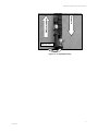
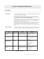
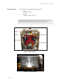
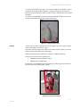
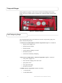
Rural Firefighting
Study
Guide
Operate
Portable
Pumps
RFPP1
ii
Status of this Document
This document is issued by the National Rural Fire Authority.
What This Means
It is written to comply with:
•
other National Training material
•
National Rural Fire Authority best practice
•
Forest and Rural Fires Act 1977
•
Fire Service Act 1975
•
Health and Safety and other relevant legislation
•
New Zealand Qualifications Authority requirements
•
Fire and Rescue Services Industry Training Organisation
(FRSITO) requirements.
The document, its content and specified processes are not to be
altered, except through National Rural Fire Authority training
processes.
Recommendations for Change
National Rural Fire Authority welcomes feedback on all its products
and processes to ensure currency and continuous improvement.
Recommendations for changes to this material should be sent to
National Rural Fire Authority.
Document title: Operate Portable Pumps
Published: July 2010
©New Zealand Fire Service– National Training
If you wish to copy or reproduce any of the material in this document, please
contact:
National Rural Fire Authority
National Training
PO Box 2133
Wellington
Ph: (04) 496-3600
Fax: (04) 496-3700
Contents
Acknowledgements ................................................................................................................................................ i
Study Guide Introduction ..................................................................................................................................... 1
Section 1: Basic Hydraulics ................................................................................................................................. 3
Introduction .......................................................................................................................................................... 3
Principles of Pressure ..................................................................................................................................... 6
Flow in Hose Lines ............................................................................................................................................ 12
Section 2: Knowledge of Portable Pumps......................................................................................................... 14
Pump Types ...................................................................................................................................................... 14
Summary ........................................................................................................................................................... 20
Section 3: Set up Portable Pumps ..................................................................................................................... 21
Types of Water Supplies ................................................................................................................................... 21
Suitability of Water Supply................................................................................................................................. 23
Assessment of Water Supply ............................................................................................................................ 23
Section 4: Operate Portable Pumps .................................................................................................................. 28
Engine Troubleshooting..................................................................................................................................... 33
Relay Pumping .................................................................................................................................................. 36
Communication.................................................................................................................................................. 45
Section 5: Recommissioning and Site Restoration.......................................................................................... 47
Retrieving and Recommissioning Equipment .................................................................................................... 47
Maintaining After Use ........................................................................................................................................ 48
Restoring the Site .............................................................................................................................................. 49
i
Operate Portable Pumps-Study Guide
Acknowledgements
The National Rural Fire Authority (NRFA), New Zealand Fire Service (NZFS)
and the Fire and Rescue Services Industry Training Organisation (FRSITO)
acknowledge the help of the many subject matter experts in preparing this
course.
i
Operate Portable Pumps- Study Guide
Study Guide Introduction
Overview
Welcome to Operate portable pumps. The course is made up of theory and
practical training.
During the course, you will learn about:
•
basic hydraulics
•
knowledge of portable pumps
•
set up portable pump
•
operate portable pump
•
recommissioning and site restoration.
Read through this study guide and complete the workbook before your
practical training date. This will ensure you are familiar with the subject and
can highlight any questions for the training session.
Course Objectives
The general objectives for this course are to demonstrate knowledge of
portable pumps and how to set up, operate and recommission a portable pump
appropriate to your firefighting working environment. After studying this
material, you should be able to demonstrate knowledge of:
•
basic hydraulics; properties and characteristics of water
•
portable pumps used in firefighting
•
setting up a portable pump
•
operating a portable pump
•
recommissioning a portable pump and restoring a site.
This course provides evidence towards the achievement of Unit Standard
20386 (version 2) Operate portable pumps for fire fighting.
Assessment and
Evidence
Because practical experience differs you will need to check with an approved
assessor and discuss the requirements for you to achieve the unit standard. This
could include attestation of previous practical experience and/or practical
assessment.
A properly maintained work record will support your portfolio of evidence for
use as evidence for assessment against unit standards. You’ll need to maintain
a record of relevant work experience, together with an evaluation of tasks
completed at an incident by the relevant supervisor.
July 2010
1
Practical Training
The practical training session is made up of two parts:
1. The instructor provides leadership in the use of firefighting portable
pumps and the trainees practice using each item.
2. Participants work in a crew to set up and use firefighting portable
pumps and practice these skills.
Gaining the Unit
Standard
2
For the unit standard assessment participants may submit a portfolio of
evidence to a designated assessor. To support the evidence, maintain a
workbook and records of relevant work experience, together with an evaluation
by the relevant supervisor of tasks completed at an incident.
New Zealand Fire Service National Training
Operate Portable Pumps- Study Guide
Section 1: Basic Hydraulics
Introduction
Basic Hydraulics
Hydraulics deal with the physical characteristics displayed by fluids at rest and
in motion.
Hydraulics = hydro (water) aulos (a pipe) (Greek)
In firefighting, hydraulics is generally used to describe the study and behaviour
of water. Every time you work with water you are employing hydraulics.
Understanding the application of hydraulics in your role as pump operator is
essential.
As a firefighter you will already be aware that water is the most commonly
used fire-extinguishing agent. For water to be used effectively, it needs to be
applied in a suitable form and at a rate high enough to overcome the heat of a
fire. To achieve this knowledge you need to know about hydraulics and pump
operation.
Water Hammer
When the flow of water through fire hose or pipe is suddenly stopped, the
resulting surge is referred to as water hammer.
Water hammer can often be heard as distinct sharp clank, very much like a
hammer striking a pipe. This sudden stoppage results in a change in direction
of energy and this energy is instantaneously multiplied many times. These
excessive pressures can cause considerable damage to water mains, plumbing,
fire hose and fire pumps.
Jet Reaction
When water is projected from the nozzle, a reaction of equal and opposite force
to the force of the water jet takes place. This causes the nozzle to recoil in a
direction opposite to the flow.
Jet reaction is the force generated by the moving jet of water exiting a nozzle.
As a pump operator, you need to be aware that a nozzle and hose under control
will whip around at high speed if not under control, and can cause serious
injuries and damage if it strikes people or objects.
Sudden variations in pressure at the nozzle can also unbalance the firefighter
holding it if the jet reaction takes them by surprise. Opening valves too quickly
is the most common way of rapidly altering the jet reaction.
This reaction takes place as the water leaves the nozzle and is not affected by
the jet striking, or not striking, a nearby object.
July 2010
3
Safety Note:
!
While operating a pump, you need to be ready to react to an out-of-control hose by
shutting off the water
Characteristics of nozzle
discharge
Water is usually applied in the form of either a jet or a fog/spray. Sometimes it
is mixed with a foam concentrate and air and applied as foam.
An open-ended fire hose may be able to supply a sufficient rate of water flow,
but unless a nozzle is added and water is supplied at an appropriate pressure, it
may not be in a suitable form (jet or spray) to apply to a fire.
Figure 1.1 – Hose with Jet
Figure 1.2 – Hose with Spray
4
New Zealand Fire Service National Training
Operate Portable Pumps- Study Guide
Function of the nozzle
The nozzle controls the flow and pattern of the water being discharged.
Discharge through the
nozzle
Each nozzle will operate at an optimum pressure. These pressures cannot
always be adopted during firefighting operations. They depend on the
condition of the hose, the length of hose lines, the height of the nozzle above or
below the pump, the capacity of the pump, and many other factors.
Optimum nozzle pressure is the pressure at which the nozzle delivers the best
volume of water, usually in the 500 – 700 kPa range.
The advantages of using optimum nozzle pressures are:
•
greater striking power and reach
•
larger volumes of water
•
less turbulence in the water jet
•
less jet reaction.
Exceeding the optimum nozzle pressure, does not usually create any advantage.
Excessive turbulence in a water jet at a higher pressure, may lead to it breaking
up prematurely and reduce its effective range.
Excessive pressure also creates an unnecessarily high jet reaction, making the
delivery more difficult for firefighters to use and control.
!
July 2010
Safety Note
Nozzle controls, hydrants, valves and hose clamps should be operated slowly
to prevent water hammer.
5
Physical Properties of Water
Water when pure is colourness, odourless and tasteless. It exists as a fluid
between 0°C and 100°C and for all practical purposes it is considered
incompressible. Water is incapable of resisting change of shape, always
assuming the shape of the vessel in which it is contained, and will come to rest
with a level surface.
One cubic metre (m3) of water = one tonne (t) = 1,000 litres (l)
1 litre of water has a mass of 1 kilogram (kg)
Force is the amount of energy to shift water (kilowatt - kW) and is related to
the size and power of the pump.
Mass is the weight of water.
Expansion
Expansion is when water expands by either heating to steam or cooling to ice.
This water expansion can damage the pump.
Principles of Pressure
Pressure
Pressure is the force acting on a given surface area. It is usually measured in
kilopascals (kPa).
Energy is needed to provide a flow of water to the nozzle with sufficient
pressure to form an effective jet, fog/spray or foam stream. Usually this energy
is imparted to the water by a pump. Pump operators control the flow and
pressure of water being supplied to firefighters at the nozzle.
As the water travels through the hose on its way to the nozzle, there is a loss of
energy due to:
•
the height of the nozzle above the pump
•
friction in the hose.
Pump operators need to provide the correct pressure at the pump to overcome
both these losses so the pressure delivered at the nozzle(s) is sufficient to form
an effective jet, fog, spray or foam stream. To achieve this, a good
understanding of the principles of pressure is required.
6
New Zealand Fire Service National Training
Operate Portable Pumps- Study Guide
Head loss (or gain)
Water flowing uphill from the pump to the nozzle needs more pressure to
overcome the effect of gravity. The opposite happens if the nozzle is lower
than the pump – less pressure is needed to send water downhill.
Head is defined as the difference in height (in metres) between the nozzle and
pump.
Suction Lift
Suction lift is the distance from the pump to the level of water that you are
drafting from.
Ejector Pumps
Ejector pumps are special pumps with no moving parts.
This type of pump is particularly suitable where it would otherwise not be
possible to place a normal pump. They are used away from the appliance, as an
extension to the appliance pump. They can pump dirty water without causing
any damage to the ejector pump.
Ejector pumps are light and easy to handle. Once set up, they require little or
no attention, except any removal of debris that may have collected in the
suction strainer.
There are three common ejector pumps:
1. A Type
2. B Type
3. Water Dragon.
Only A and B types will be discussed below.
‘A’ Type ejector pumps
The ‘A’ type ejector pump is a salvage ejector pump only. It uses 100 mm
suction to move large volumes of water.
July 2010
7
Drive Water
To waste
Induced water
Figure 1.3 – ‘A’ Type ejector pump
Barrier Height
Barrier height is the maximum height a pump is capable of delivering to,
particularly in reference to the operation of B Type ejector pumps.
Caution: do not restrict flow by running over obstacles or obstructions to flow,
particularly with discharge line from ejector pumps.
You need to add 10 kPa for every metre the nozzle is higher than the pump.
This is particularly important for ejector pumps.
If the nozzle is below the pump then you need to subtract 10 kPa for each
metre. This is particularly relevant in low pressure pumping situations, for
example when using a ‘B’ type ejector pump.
Head
Head is the height from the outlet of the pump to where the water is being
delivered.
‘B’ Type ejector pumps
The ‘B’ Type ejector pump (see Figure 1.5) can be used as a salvage pump for
minor flooding as well as providing water supply in non-reticulated areas. It
has three connections. The pump is designed for use with a 70 mm delivery
hose, so the connections are:
• 70 mm male on the inlet side
• 70 mm female outlet.
The pump incorporates a strainer, so no suction connection is required.
8
New Zealand Fire Service National Training
Operate Portable Pumps- Study Guide
Drive water
Return water to pump
Induced water
Figure 1.4 – ‘B’ Type Ejector Pump
July 2010
9
Characteristics of Suction Lift
When using suction, water cannot rise to a vertical height of more than 10 m.
Water rises because it is forced up by atmospheric pressure.
To aid pump operators in recalling the factors the word ‘CRESTA’ is can be
used to help you remember.
C
Creation of flow
A proportion of atmospheric pressure is used
in creating flow. This varies in proportion to
the velocity of water in the suction hose.
R
Resistance to friction
Overcoming frictional resistance to the water,
both on entering and on passing through
strainers and suction hose. Frictional loss in
suction hose is governed by the same factors
as apply with delivery hose: Length, Interior
Surface, Diameter and Speed of flow
E
Entry loss
Due to changes of direction as the water enters
the pump impeller.
S
Size of suction hose
The larger the diameter of the suction hose the
greater the flow.
T
Temperature
Water boils at 100°C at normal atmospheric
pressure. At pressures less than atmospheric,
as in suction hose, water will boil and
vaporise at lower temperatures. When it
vaporises in suction hose, the column of water
becomes broken and the pump loses its prime.
Approximate heights to which water can be
lifted in suction hose at temperatures above
normal are shown in Figure 1.7.
A Atmospheric pressure
10
Atmospheric pressure is the only pressure
available to lift water in a suction hose. The
primer of a pump only extracts air so
atmospheric pressure may induce water to
enter the pump.
New Zealand Fire Service National Training
Operate Portable Pumps- Study Guide
Vertical Lift
The primer creates a vacuum in the pump and suction hose. The lifting of water
to the pump inlet and the flow into the pump is then achieved only by
atmospheric pressure.
The practical maximum lift applies only to cold pure water at sea level.
Water
Temperature
25°C
55°C
72°C
82°C
Above 88°C
Approximate
lift height
8m
6m
4m
2m
Nil
Figure 1.5 – Approximate lift heights of water above normal
temperatures
When operating a pump, the height of the pump inlet above the water surface
needs to be considered. This is called vertical lift.
An example of this is when the pump inlet is 3.0 metres or less above the
surface of the water. In this example your pump will be running at its full
capacity. By the time the pump is 7.0 metres above the water, you only have
half of the rated capacity of the pump.
Air Leak in Suction
If an air leak were to occur, the suction hose would not maintain a vacuum and
the pressure in the suction hose means you lose the prime in the pump. Losing
the prime in the pump will result in damage to the pump, and of losing water at
the nozzle.
Negative Pressure (pump inlet)
Firefighters usually refer to pressure above atmospheric pressure as positive
pressure, and pressure below atmospheric pressure as negative pressure.
When the pump is using water from a static supply, there is a negative pressure
on the inlet side of the pump. The amount of negative pressure normally
corresponds to the lift of water being achieved.
If the suction hose or pump inlet were to become blocked the pump would
work harder to lift water against the blockage. If the blockage is not cleared
the pump flow is reduced or the prime can be lost.
July 2010
11
Flow in Hose Lines
Friction Loss
Pressure is lost because of friction in the hoses. Several things cause friction,
including the size of hose being used and the water flow.
The diameter of a hose affects the amount of pressure lost due to friction.
Small hoses generate more friction than bigger hoses, so they need more
pressure to push water through them. Larger hoses reduce the friction loss,
which in turn reduces the pressure required to push water through them.
The table below shows the approximate friction loss for different hose types
per length. These amounts are for low flow rate and will differ depending on
type of inner lining in the hose. High and low flow rates are discussed next.
Hose Diameter
25
41
45
70
90
Friction loss (kPa)
350
200
150
60
50
Hose Length
30
30
25
25
30
Figure 1.6 – Effects of friction loss
12
New Zealand Fire Service National Training
Operate Portable Pumps- Study Guide
Friction loss due to flow
rate
The flow rate of water is governed by the pump rated output and restrictions in
waterway fittings i.e. nozzle fitted or open ended hoses. A low flow rate is
anything under 475 litres per minute. A high flow rate is anything higher that
that. Some pieces of waterway equipment, like large nozzles and ground
monitors require a high flow rate.
The higher the rate, the more pressure is lost due to friction.
High flow rate = more water pressure lost
Low flow rate = less water pressure lost
For example, for a 70 mm hose, the pressure loss per length is:
Flow Rate
Length of hose section
Pressure loss per
length
Low flow rate
25 m
15 kPa
High Flow rate
25 m
50 kPa
A high flow rate should only be used with larger hoses, like 90 mm hoses.
Smaller hoses, like 41 and 45 mm hoses should only be used with a low flow
rate. Both rates can be used with 70 mm hose.
Friction loss decreases when running two hoses in parallel.
For example, if water is being delivered through one hose line at a particular
rate of flow, and a second parallel hose line (same diameter) is brought into
operation. Each of the parallel hoses will only need to flow half as fast to
deliver the same total flow rate. However, the friction loss in each will be
reduced to a quarter of its original value in the single hose line.
Friction loss increases with the roughness of the interior of the hose.
All other factors being equal, a hose that has a rough interior (an unlined hose)
will have greater friction loss than will a hose with a smooth interior (a rubber
lined hose).
General Rules
1. The general rule for pumping water over a significant distance is that
using larger diameter hose reduces friction loss.
2. The general rule when already using a larger diameter hose is that in
order to reduce friction loss in the hose line you need to ‘twin’ the hose
line.
3. The pump operator should know the flow and pressure required at the
end of the hose line to then set the pump output. Delivery
requirements plus hose lengths (friction loss) equals required pump
output.
July 2010
13
Section 2: Knowledge of Portable Pumps
Pump Types
Portable Pumps
An effective pump operator must be able to operate portable pumps from both
open water and pressure-fed supplies.
Portable pumps are independent pumping units that can be carried by one or
several firefighters. They are usually centrifugal pumps powered by a small
diesel engine or two-stroke or four-stroke petrol engines.
Portable pumps may be stand-alone units for use away from an appliance, fixed
to the deck of an appliance or trailer, or carried as part of a firefighting unit
designed to be carried on a utility or trailer.
Portable pumps have lower outputs than appliance-mounted-and-driven pumps.
They are smaller and may not incorporate the usual pump gauges. Some
portable pumps may also be designed as floating units, with an integral suction
inlet.
Pump Classification
Type
The National Rural Fire Authority pump categories are listed below, along with
their abbreviations and examples of the pumps that meet each classification.
Abbreviation
High Pressure / Low
Volume
HP/LV
Low Pressure /
Medium Volume
LP/MV
Capacity
Examples
100 l/min at 1700 kPa
(light portable pump)
Wajax MK3 and MK 5
300 l/min at 200 kPa
Firemaster HP50, HP80
Wick 375
Waterous Floto STD
Aqualite
Medium Pressure /
Medium Volume
MP/MV
500 l/min at 500 kPa
Firemaster 10, 18
Waterous PB18 2515
Tohatsu V30
Millienium
High Pressure / High
Volume
HP/HV
900 l/min at 700 kPa
Firemaster 15, 20, 35
1100-1500 l/min at 400
kPa
Waterous E603
Tohatsu V40
Figure 2.1 - Pump types
14
New Zealand Fire Service National Training
Operate Portable Pumps- Study Guide
Pump Components
The following are components of portable pumps:
•
starter
- manual or electric
•
fuel types
- 4 stroke, 2 stroke or diesel
Note: Each pump has different components. You will need to be able to
identify and explain your agencies or organisations pump types.
Figure 2.2 – Millenium (HP/HV)
Figure 2.3 – Pumps with gauges
July 2010
15
Figure 2.4 – Waterous (MP/MV)
Figure 2.5 – Aqualite Pump
Figure 2.5a –Pump
inlet
16
Figure 2.5b – Camlock
suction hose 70 mm
New Zealand Fire Service National Training
Operate Portable Pumps- Study Guide
Figure 2.6 – Screw thread
July 2010
17
Pump Specifications
NRFA
Portable
Pump
Category
High
Pressure/
Low
Volume
(HPLV)
Low
Pressure/
Medium
Volume
(LPMV)
Medium
Pressure/
Medium
Volume
(MP/MV)
High
Pressure
/ High
Volume
(HPHV)
Minimum
Capacity
for NRFA
Category
Max
Pressure
Max
Suction
Lift
Inlet size
& Type
Outlet size &
Type
Fuel
Type
Primer
Type
Approx.
Weight
Examples
100 lts/min
at 1700 kPa
2100
kPa
2m
50 mm
male
Camlock
1 x 41 mm male
screw (Forestry)
2- stroke
35 - 40kg
Wajax
thread
Hand primer
or use of
footvalve
300 lts/min
at 200 kPa
350 - 450
kPa
4m
75 mm
male
Camlock
1 x 70 mm
female
Instantaneous
4- stroke
Bucket fill
60 - 70kg
Aqualite
500 lts/min
at 500 kPa
700 - 800
kPa
6m
75 mm
male
Camlock or
100 mm
1 x 70 mm
female
Instantaneous
2- stroke
and
4- stroke
Mechanical
primer
80 - 100kg
900 lts/min
at 700 kPa
1000 1100 kPa
8m
100 mm
male
Round
Thread
2 x 70 mm
female
Instantaneous
2- stroke
and
4- stroke
Mechanical
primer
120 - 135kg
Firemaster
HP80
Millenium
Waterous
PB18
Angus 1200
Firemaster 20
Figure 2.7 – Pump Specifications
This table is a general summary of the various portable fire pumps. Check your pump operator manual
for specific details.
Figure 2.8 – HPHV Kit
18
New Zealand Fire Service National Training
Operate Portable Pumps- Study Guide
Routine Maintenance and Testing
A typical maintenance regime consists of checking the following:
•
fuel level
•
crank case oil level
•
that all switches are off
•
that valves operate freely and are set for priming
•
that the pump is correctly stowed with its suction hose and strainer
•
that intakes and strainers are clear
•
the condition of the suction hose and strainer
Regular checks have been conducted:
•
carrying out an inspection (monthly)
•
the pump should be test run regularly (minimum 3 monthly)
•
if pump is being used in salt water the pump will need to run from
clean water for at least 20 minutes. Salt water is corrosive.
•
ensure correct fuel type for portable pump engine
•
annually, or if a fault is detected, servicing is to be carried out to the
manufacturer’s specifications by an approved service technician.
(NRFA standard requirement)
Note: The frequency of testing will be specific to your agency or
organisation.
Check the manufacturer’s instructions regarding maintenance for specific
portable pumps.
July 2010
19
Summary
20
•
Portable pumps are independent pumping units that can be carried by
one or several firefighters.
•
Portable pumps have lower outputs than appliance-mounted-anddriven pumps.
•
Suction hose for portable pumps is usually in a single length and fitted
with a strainer and float (optional).
•
Not all portable pumps have gauges.
New Zealand Fire Service National Training
Operate Portable Pumps- Study Guide
Section 3: Set up Portable Pumps
Types of Water Supplies
Types of Water Supplies
Firefighting water supplies come in three basic groups:
• static water supply
• pressurised water supply
• mobile water supply.
Static Water Supply
Static water supplies can include:
• lakes
• rivers and streams
• ponds
• dams (fixed or portable)
• the sea
• swimming pools
• wells.
Pressurised Water
Supplies
Pressurised water supplies are those in which water is distributed under
pressure for example:
• urban water mains (reticulated supply)
• pressure fed from another pump
• gravity feed from an elevated tank.
Mobile Water Supplies
Mobile supplies are those by which water is transported to the fire ground from
a distant source, for example:
• tankers
• fire appliances.
Limited Water Supplies
Limited water supplies often include:
• tanks
• wells
• portable dams
• natural and manmade dams
• swimming pools.
A limited supply must be used sparingly. If the supply is insufficient, water
July 2010
21
may need to be brought to the fire ground, or dry firefighting techniques may
need to be used.
Portable Dams
Portable dams can be purpose-built or improvised, and they can be used for a
number of purposes:
• to hold a water supply delivered by tanker
• as part of an open relay
• as large ‘Dipping Dams’ for filling helicopter buckets
• for the mixing of additives with water.
Unlimited Water
Supplies
An unlimited water supply has either a volume or a flow that is far in excess of
your requirements, for example:
• the sea
• rivers
• lakes.
22
New Zealand Fire Service National Training
Operate Portable Pumps- Study Guide
Suitability of Water Supply
Pre-planning
Pre-planning identifies suitable water supplies in advance of an incident. This
reduces the time and effort required to locate and establish a water supply
when required.
Hidden Water
Supplies
Water supplies are not always apparent. They can be:
• hidden from view behind or under vegetation
• too low a flow to be useful.
Hidden water supplies can be assessed and recorded as part of pre-planning.
Access
Access to a water supply can limit its usefulness. Potential solutions can
include:
• cutting an access track through vegetation
• clearing and/or flattening out a space for a portable pump.
Assessment of Water Supply
Not all water sources are suitable for firefighting use. You need to be able to
assess a supply and decide upon its suitability for firefighting.
Location
Access
July 2010
When assessing a water source for firefighting purposes, consider the
following:
•
is it adjacent to the fire area?
•
will the location be threatened by the fire or smoke?
•
are there adequate communications at this point?
•
is there a safe escape route?
•
has a safety zone been identified?
When assessing the accessibility of a water source for firefighting purposes,
consider the following:
•
what type of pump will be used (portable, trailer or vehicle
mounted)?
•
how close to the water can the pump be located?
•
is there firm ground on which to place the pump or park the
appliance?
•
can the pump be safely carried or driven to the pump site?
•
is the site tidal or does the water level rise and fall (eg hydro-power
23
rivers or irrigation canals) during the day?
•
Quality
what are the requirements of the pump/s being used?
When assessing the quality of water available for firefighting purposes,
consider the following:
• fresh water is better than stagnant water
• clear water is better than muddy water
• is it weedy or does it have floating debris?
• hard ground is better than soft ground
• when the pond level is lowered, will you be left with only mud?
• sea water is corrosive and hard on equipment.
Quantity
When assessing the quantity of water available for firefighting purposes,
consider the following:
• how much is there? how much will you need?
• is it a limited or unlimited supply?
• is there an in-flow of water to top up the supply?
Depth and Flow
Suction hose in shallow water will tend to create a vortex (whirlpool) that
allows air to be drawn into the pump. Air in the water entering the pump can:
• reduce performance
• cause the pump to lose its prime.
Estimation of Volume
To calculate the capacity of a rectangular swimming pool or tank:
Capacity (in litres) = length (m) × breadth (m) × depth (m) × 1000
If the container has an uneven depth, the average depth in the calculation is
used:
Capacity (in litres) = length (m) × breadth (m) × average depth (m) × 1000
For example:
A pond is approximately 5 metres by 10 metres and varies from 1 to 3
metres deep.
Capacity (in litres) = 5 (length) × 10 (breadth) × 2 (average depth) × 1000 =
100,000 litres
Your estimations will have to take into account the practicalities of how much
water you can actually use. You may not be able to use the bottom 300 mm of
depth due to debris at the bottom of the pond or other limitations due to hose
length etc. The section on improving water supplies deals with some of the
possible limitations on supply and ways to counter them.
24
New Zealand Fire Service National Training
Operate Portable Pumps- Study Guide
Usage Rate
The usage rate is the volume of water that is used in a given period of time. By
estimating the usage rate, you can estimate:
• how long a limited supply will last
• whether you can supply water fast enough to satisfy demand.
To estimate the usage rate, you need to know:
• how many pumps will be used
• the approximate output capacities of each pump.
To find the usage rate of one or more pumps, add the output capacities of all
the pumps using the same supply.
For example:
1 × medium volume pump @ (900 litres per minute) 54,000 litres per
hour and
2 × Wajax pumps @ (150 litres per minute) 9000 litres per hour, per
pump.
54,000 + 9000 + 9000 = 72,000 litres per hour
Duration Estimation
To estimate how long you will be able to supply water from a fixed supply,
divide the capacity of the supply by the usage rate.
For example using an Aqualite pump in a 50,000 litre swimming pool:
50,000 litres
= approximately 55 minutes
900 litres per minute
Water
supply
Volume
Pump
Pump
output
Duration of
supply
(approx)
Large pond
50,000 lt
Aqualite
900 lt/min
55 mins
Large pond
50,000 lt
Wajax
150 lt/min
5 hrs
30 mins
Portable
dam
2,000 lt
Wajax
150 lt/min
13 mins
Fire
appliance
2,000-3,600
lt
Wajax
150 lt/min
24 mins
Fire
appliance
3,600 lt
Darley or
other PTO
pump
1320 lt/min
3 mins
Figure 3.1 – Examples of duration of various supply and pump combinations
July 2010
25
Loose Material
Mud, silt, vegetation, stones and rubbish in the water supply can block the
strainer on the suction hose, reducing the volume the pump can deliver.
There are ready-made suction trays and any number of improvisations that can
minimise this problem.
Note: Place the suction hose in water with a depth of at least three times the
diameter of the strainer to prevent a vortex forming.
Selecting the Site
When you are considering your requirements and selection of the site you need
to consider:
•
access to the site for both pumps and people
•
portable pump should be positioned on a flat, firm surface in an
accessible place. A floating pump may need to be tethered. Hoses may
need to be protected from chafing by pump vibrations.
•
suction lift
•
firm ground
•
site drainage
•
hazards including loose material uphill, passing traffic
•
quality and quality of water
•
airflows (fumes and smoke)
•
danger from fire.
Safety and Hazards
When handling portable pumps, it is important to employ correct lifting
techniques.
Always:
•
Use correct lifting and carrying techniques when handling portable
pumps.
• size-up load and get help if necessary
• hold the pump firmly, keeping your arms close to your body
• keep your backs straight
• avoid twisting when lifting
26
New Zealand Fire Service National Training
Operate Portable Pumps- Study Guide
• lift using your leg muscles, not your back muscles
• ensure that there are enough people for the task
• keep the load level and balanced.
Other hazards include:
1. Exhaust fumes
Operate these pumps only in well-ventilated areas.
2. Hot exhausts
Ensure that safety guards are adequate. Wet down the surrounding
area or remove vegetation that is at risk of igniting and place out fire
extinguishers.
3. Fuel spillages
Make spillages safe: follow the procedures for refuelling hot engines.
4. Engine seizure
Ensure that the pump is kept level when operating on an incline in
order to maintain oil feed to the engine.
5. Excessive noise
Ensure that adequate hearing protection (Class 4 earmuffs) is worn
when you are operating portable pumps.
6. Drowning
Take care near deep water sources.
7. Hose burst
Take care when closing the delivery valve on a second or later pump in
a closed relay line, as this may cause an over pressure in the pump and
inlet fittings.
July 2010
27
Section 4: Operate Portable Pumps
Operating a Portable Pump
Pump Kit
Ensure that you have all of the equipment required to operate the pump before
you commence setting up to operate. A pump kit may include:
Figure 4.1 – Pump Kits
Suction Hose
Rural fire authorities commonly use 75 mm camlock suction couplings for the
medium size portable pumps and 100 mm round thread for the large portable
pumps. The NZFS has standardised on 100 mm suction hose for both medium
and large portable pumps. Suction hoses are manufactured of either flexible
wire bound composite hose (50 mm and 75 mm diameter) or the more rigid
rubber compound (100 mm diameter). They are used to get water from a static
water supply, such as a dam, pool, or river to portable pumps.
Figure 4.2 –75 mm and 50 mm camlock with wire bound
composite suction hose
28
New Zealand Fire Service National Training
Operate Portable Pumps- Study Guide
Figure 4.3 –75 mm camlock coupling with
strainer
Figure 4.4 –75 mm camlock to 100 mm round thread
adaptor for pump inlet
100 mm Round Thread
They are connected with screw couplings. These couplings must be tightened
with a suction hose spanner.
You will need two fire fighters to connect suction hoses together.
Figure 4.5 – Hand tighten suction hose couplings
July 2010
29
Tighten the joints further using suction hose spanners. Tighten by turning the
spanners clockwise.
Figure 4.6 –Tighten with spanners
Connect the suction hose to pump
Figure 4.7 –Connect to pump
Use a rope to support suction hose when lowering to water supply.
Figure 4.8– Supporting the suction hose
30
New Zealand Fire Service National Training
Operate Portable Pumps- Study Guide
Tie off the suction hose by tying a clove hitch around the suction hose. This is
to support the weight on the couplings. Creating a bend in the suction hose
takes the weight of the hose when it is full of water, and takes the strain off the
couplings.
Tie each set of couplings to the next set using a half hitch. Make sure you tie
the knots around the strainer side of the suction hose.
Figure 4.9 –Tying off suction hose
Priming
‘Prime’ refers to having the suction hose and pump case full of water. If they
are not, the pump will not move water.
The pump will not pump water if there is air in the suction system. You must
remove air from the intake side of the pump.
Light portable pumps are primed by a number of different methods.
There are two main forms of priming are:
1. Mechanical primer (exhaust, rotary)
2. Manual primer (diaphragm).
Each pump is primed differently and during your training you will be shown
how to prime your organisations’ pumps.
Figure 4.10 –hand operated primer
July 2010
31
Issues with Priming
Emergency Priming
32
If the pump will not prime or loses prime check for:
•
suction strainer not fully in water
•
damaged / missing suction washers
•
loose connections above water or hole in suction
•
delivery value open
•
sharp bend in suction hose e.g. over bridge parapet
•
blocked strainers
•
faulty foot valve (if fitted)
•
damaged suction hose
•
water level dropped
•
water too hot for drafting
•
pump drain not closed.
In practice emergency priming is extremely difficult to achieve. The best
option is to replace the pump. If a trainer wishes to demonstrate a technique
this is at the discretion of the trainer.
New Zealand Fire Service National Training
Operate Portable Pumps- Study Guide
Starting the Engine
You need to be able to start and operate your agency or organisations portable
pump.
You need to be able to start each pump from a cold start or hot start.
Guidelines
Do not run the pump if it is not fully primed.
Keep the pump as close to the water as possible.
Keep the suction hose as short as possible.
Keep all connections clean.
Keep all connections tight - use suction spanners to tighten connections.
Keep suction strainer clear of debris.
Keep pump strainer clean of debris.
Operate portable pump in a well ventilated area; take appropriate precautions
to guard against the hazards created by hot exhausts and during refuelling.
Do not pump silty water.
Engine Troubleshooting
Troubleshooting Tips
If the engine fails to start or is not running properly, check the following:
1. Ignition switch, set to ON.
2. Fuel tap, turned to ON.
3. Fuel tank vent, set to OPEN.
4. Fuel level, tank full.
5. Choke - closed for cold starting or flooding, open for hot starting.
6. Air intake, clean and unobstructed.
7. Spark plug, is it clean?
8. Is the engine flooded?
Engine Flooded
Repeated attempts to start an engine can cause excess fuel to ‘flood’ the
engine. Different engines have different procedures for dealing with flooding.
Safety Note:
!
July 2010
If a fuel tap is fitted this should be turned off when the pump is stored on appliance
or depot.
33
Pumps with Gauges
Some pumps have gauges. These can be used for fault finding when using a
pump. The most common gauges on pumps are compound gauges and pressure
gauges.
Figure 4.11 – Example of Gauges
Fault Finding using Gauges
The compound gauge shows an increase in vacuum. The pressure gauge will
show a decrease in pressure.
An increase in vacuum and/or a decrease in pressure might be a resulted of:
•
drop in water supply level
•
blocked suction strainer
•
blocked strainer
•
suction strainer sinking in to mud
•
burst delivery hose
•
suction hose internally collapsing.
A decrease in vacuum and/or a increase in pressure might be a result of :
•
rising water supply level
•
loose suction couplings above the water
•
open primer valve
•
loose/open drain plug
•
pin holes in suction.
A sudden increase in pressure could be caused by:
34
•
a closed nozzle
•
a badly kinked hose.
New Zealand Fire Service National Training
Operate Portable Pumps- Study Guide
Engine revs constant but a sudden decrease in pressure could be caused by:
•
an opened nozzle
•
a burst delivery hose.
When a pump operator is attempting to deliver more water than is available
this will show on the gauge as fluctuating pressure. This could result in a
seriously damaged pump.
Refuelling
Before Refuelling
Stopping the pump to refuel needs to be carefully managed to minimise the
disruption to the firefighters you are supplying with water.
To make the refuelling stoppage as short as possible, do the following:
During Refuelling
1.
Ensure you have enough fuel of the correct type. Check that the fuel
container and its’ label have the same colour code.
2.
Notify the nozzle operator.
3.
Ensure everyone relying on the hose lines you control has backed
off to safe positions.
4.
Close down the hose line supply.
5.
Stop the engine.
1. Avoid spilling fuel by using a funnel and pour slowly.
2. In calm conditions, wait for a minute after refuelling to allow fuel fumes
to clear.
3. Check the state of the soap capsules in the hydroblender, or foam supply.
!
July 2010
Safety Note:
Care must be taken while refuelling as the pump is hot and could cause a fire.
35
Relay Pumping
Water Relay
The provision of water at a fire where nearby water supplies are either
inadequate or non-existent is at times a difficult operation and one that must be
carried out with the equipment available at the time.
Where such situations arise, it will be necessary to implement a water relay. A
water relay comprises a number of pumps spaced at intervals along the route
between the water source and the point where the water is required. Each pump
in the relay receives water and passes it along the next pump until the desired
delivery is achieved. The additional pumps are, in such circumstances, referred
to as relay pumps.
Largest capacity pump at the water source and then the spacing of the
respective pumps will depend upon the capability of each individual pump, the
task it has to perform and the terrain over which its performance is required.
There are two water relays in general use:
Relay Types
Reasons for Relay
Pumping
•
the closed relay
•
the open relay.
A pump can be introduced into a relay system either by:
•
using a relay adaptor, known as a closed relay or pressure-fed system
•
using a portable dam/s, known as an open relay or static system.
If the distance or height over which water must be delivered is too great, a
relay pumping system will be required.
Closed Relay Pumping
In a closed relay, water is pumped by the first or base pump from the water
source, which maybe a tank, hydrant or open water source through hose
lines connected directly to the inlet of the second or booster pump. The
second pump in turn may be connected to a third and subsequent pump until
the final destinations is reached.
Connecting the delivery hose from one pump directly to the inlet of the next
pump using a relay adaptor is called a closed relay system.
Each pump in the relay boosts the pressure, making up for the losses from
friction and pumping uphill, to ensure there is adequate pressure at the
nozzle.
36
New Zealand Fire Service National Training
Operate Portable Pumps- Study Guide
Figure 4.13 – Relay Adaptor
Figure 4.12 – Pump in a closed relay being fed via a relay
d t
Advantages
The closed relay is generally considered to be more suitable than the open relay
for several reasons.
•
there is economy in the equipment used.
•
there is greater speed in setting up the system.
Closed relay results in a continuous flow of water from the base pump to the
final discharge pump.
Disadvantages
To be fully effective, the closed relay demands a higher standard of pump
operation than normal. The operator must carefully watch pump gauges, pump
speed, and the hose lines supplying the pump, for fluctuations in the supply.
Where the pumps have no gauges, the operator must rely on continually
observing the hose line supplying the pump.
The term ‘soft suction’ refers to the process where water is supplied to a pump
by a conventional ‘soft’ delivery hose as opposed to a ‘hard’ suction hose.
July 2010
37
Figure 4.14 – Closed Relay
Delivery hoses are designed to resist internal pressure. If the supply cannot
meet the demands of the relay pump there will be a tendency for the relay
pump to draw more water from the line than the volume available. In such
circumstances, the reduction in volume will collapse the hose.
Another disadvantage of the closed relay is that any problems with any unit in
the system will affect the whole system. If the base pump fails it will result in a
break in the water supply. However, if any other pump in a closed relay fails
water will continue to flow although at a lower flow and pressure.
Safety Note
!
When engaged in a closed relay pump operators must watch for any changes in
the incoming hose line. When you see this the pump speed must be reduced
until the incoming hose is firm again.
Failure to see changes in the incoming hose will result in total collapse of the
hose line and a total cutting off of the water supply.
38
New Zealand Fire Service National Training
Operate Portable Pumps- Study Guide
Open Relay Pumping
Delivering water from the first pump into a portable dam and taking water
from the dam via the suction hose from the next pump is called an open
system.
Figure 4.15 – Open Relay
Figure 4.16– Portable dam used as part of an open relay
July 2010
39
With open relay the base pump takes water from a source and pumps it through
hose lines into some form of reservoir. The second pump then draws water
from this reservoir through its suction hose and delivers it through delivery
hose to subsequent reservoirs and pumps until the final destination is reached.
Advantages
The open relay system offers the advantage that several pumps can draw their
supply of water from any one reservoir provided that the supply to the reservoir
is adequate. If any one of the pumping units requires replacement or
supplementing, it can be achieved without interrupting the water supply.
No special skill is required of the pump operator as each portable pump
operates under what could be described as normal operating conditions with
each operator able to monitor the water level of the reservoir from which their
pump is supplied.
Disadvantages
40
The main disadvantage with the open relay is the need to transport or construct
the reservoir for each relay pump. This may also affect the available
manpower. If any pump fails then the relay stops until remedy action is taken.
New Zealand Fire Service National Training
Operate Portable Pumps- Study Guide
Relay Pumping Tips
A relay pumping system is put in place when a single pump cannot supply
sufficient water at sufficient pressure to the firefighters who require it. To
maximise the performance of a relay:
•
use lined hose (non-percolating) for water delivery over long
distances, as lined hose produces less friction loss and provides more
water
•
use percolating hose where there is a risk of embers burning hose
•
if using a mixture of hose to run the required distance, always use the
largest diameter hose at the beginning of the system, using
progressively smaller hose as it approaches the fire ground
•
use the highest performance pump available at the water supply and
use progressively smaller pumps as the hose line progresses
•
if using a hydroblender, always move it to the last pump in a relay.
This will avoid cavitations in the pumps from capsules emulsifying.
Class A foam proportioner may remain at the first pump as the foam solution,
in a relay, will only foam on contact with air at the nozzle.
Connecting Relay
Adaptor
The following instructions are designed to get a relay adaptor connected
quickly and with minimal disruption to the pumping operation.
1. Call for water off from the base pump.
2. Disconnect the hose line at the appropriate point.
3. Place relay pump in position.
4. Connect the relay adaptor to the pump inlet.
5. Connect delivery hose from the last pump in the system to relay
adaptor.
6. Connect the hose line to the dividing breeching on the outlet side of the
relay pump.
7. Call for water on from the base pump at full speed.
8. Start the relay pump when water arrives.
Adjust the engine speed of your pump to suit the pressure of water coming into
the inlet, feel and observe the inlet hose:
•
if the hose is hard, increase engine speed
•
if the hose collapses, reduce engine speed
•
at the correct engine speed, the hose will be just firm.
If the inlet hose is still collapsed at low engine speeds, check the water supply
from the pumps below you in the system.
July 2010
41
Setting up Portable Dam
These instructions are designed to get a portable dam established and
connected quickly, and with minimal disruption to the pumping operation.
•
set up a portable dam in an appropriate position and next to a set of
hose couplings in the hose line.
•
disconnect the hose line.
•
start filling the dam.
•
place the pump in position and set it up with a suction hose as for an
open water supply.
•
wait until there is enough water in the dam to establish prime and
maintain the required flow.
•
start and run the pump.
•
monitor the level of water in the dam and prevent the pump running
dry.
•
maintain communication with the base pump operator to control the
water coming into the dam.
Relay Capacity
When organising a relay, the aim is to deliver the maximum quantity of water
according to the capacity of the available pumps and to use the minimum
amount of equipment. This can only be achieved by utilising the full capacity
of the pumps and maintaining the correct spacing between them.
With pumps of different capacity the pump with the lowest capacity should be
at the end of the relay.
The best volume performance obtained from a pump when pumping through
open ended hose may be only at half to three quarter throttle when pumping
across flat ground. Pumping uphill will require an increase in pump throttle.
Pressure energy
42
Pressure energy in a water relay circuit is expended in two ways:
•
in overcoming the static head or height, against which the water has to
be delivered
•
in overcoming the friction loss in the hose through which the water has
to pass.
New Zealand Fire Service National Training
Operate Portable Pumps- Study Guide
In circumstances where the relay is crossing reasonably level ground any
difference in level between the pumps positions in the relay may be estimated
reasonable accurately and the distance between pumps determined.
The rule of thumb for how many lengths of hose you can have between two
medium size pumps in a relay is:
Steep terrain
•
flat ground = 8 lengths (70 mm)
•
steep terrain = 4 lengths (70 mm)
If steep terrain limits your choices for pump sites, place the pump lower in the
system rather than higher.
When this occurs the static head will be of relatively little importance and the
distance between pumps will depend primarily on frictional loss in the hose.
All hose is limited in the quantity of water that it can successfully carry. Above
this hose limit frictional losses become excessive and operators must either
increase hose diameter or increase the number of hose lines.
Pump pressure
July 2010
Pump pressure increases are only possible when the pump is operating below
its designed maximum output. Any increase above the maximum output will
result in a reduced flow.
43
Fault Finding
Problem Solving in the
Field
There are many reasons that a pump may perform poorly or fail during
operations. The following table identifies some common problems and
solutions.
Problem
Failure to prime, or
prime lost
Fault
Possible Solutions
Pump not primed
correctly
Repeat priming to ensure the
suction hose and pump case are full
to overflowing.
Air leaking into
suction
Check that couplings are tight and
undamaged.
Check rubber washers in couplings
to ensure they are in place and
undamaged.
Air entering via
vortex
Increase the depth of the suction
strainer – dig a hole or dam flow if
necessary.
Place flat object, e.g. the blade of a
shovel, over the suction strainer.
Poor pump output
Blocked suction
strainer or foot valve
Clean debris off strainer.
Add a basket strainer to limit debris
build-up.
Place suction tray or blade of
shovel under strainer.
Water level dropping,
increasing loss to
suction lift
Reduce height of suction lift by
moving pump closer to water level.
Increase flow into a portable dam
to maintain water level.
Cavitation
44
Pump running faster
than available water
available can support
Reduce throttle setting, and
consider ways to improve the
supply.
New Zealand Fire Service National Training
Operate Portable Pumps- Study Guide
Communication
When portable radios are not available when using portable pump using clear,
commonly understood hand signals are less likely to be misunderstood than
shouted instructions or improvised signals.
Figure 4.17 – Hand signals for hose lines
Runners (Messengers)
When hand signals and portable radios cannot be used, messages can be sent
by runner:
• a verbal message relying on the memory of the runner is sufficient
for brief messages
• a written message will be necessary for messages that are too long or
complex to be reliably held in memory, for example messages
between crew leader and incident controller.
Personal Safety
The minimum personal protection equipment includes;
1. Basic firefighting kit (boots, fire overalls, helmet)
2. Hearing protection.
3. Gloves.
July 2010
45
Operate Portable Pumps- Study Guide
Section 5: Recommissioning and Site Restoration
Retrieving and Recommissioning Equipment
Retrieving Equipment
If different organisations have provided equipment, you need to sort and return
it to the correct organisation. It’s easy to overlook some items of equipment
and leave them behind.
Endeavour to retrieve equipment without causing damage to it or to the
environment:
• do not drag equipment along the ground, as this may cause damage.
Recommissioning
•
if you have been using foam, soap capsules or retardants, don’t flush
the equipment into a waterway.
•
take care when using vehicles to pick up equipment.
•
see ‘Water supply quality’ section regarding Didymo.
Recommissioning equipment ensures it remains in a serviceable and ready
state. All equipment must be recommissioned before storing it. This is part of
the role. Don’t leave this task to someone else.
Recommissioning equipment includes checking and servicing to ensure that:
•
all items are accounted for (use the check list/s)
•
all items are in full working order (damaged items have been tagged
and replaced)
•
pumps have been flushed with clean fresh water and refuelled
•
where used in salt or brackish water the suction hose needs to be
flushed (internal wire binding in suction hose will corrode if not
flushed)
•
used hose is replaced as required (some hose types will require drying
and repacking at a later time, while others can be rolled and re-stowed
immediately after use)
•
all equipment is re-stowed on vehicles as it usually is (or as close to as
possible) on the assumption that it will be required again at short
notice.
Even if it is not your equipment, if you have used it, then you are responsible
for recommissioning it.
Labelling of Hoses and
Pumps
July 2010
You are more likely to have your equipment returned to you (and sooner) if
you make sure it is clearly identified.
47
Maintaining After Use
Maintenance consists of checks, inspections, tests, and servicing and should be
managed in accordance to you agency or organisations maintenance plan.
Check that the Pump Kit
is Complete
Check that the Pump is
in Working Condition
With the aim of maintaining your equipment in a ready state:
•
check the contents of the pump kit against the inventory
•
check for damage to any part of the pump kit.
More than just checking the contents of the pump kit, the pump must also be
proven to be in working order:
•
perform a general visual check of the pump, looking for defects
•
check the motor controls to see that they function correctly
•
check the pump strainer and fittings
•
check the suction hose couplings to ensure that they operate correctly
and that the seals are in place and in good condition
•
test run the pump.
At the end of the test running of two-stroke engines, turn the fuel tap off to run
the carburettor out of fuel.
Clean and Refuel
Log Books and other
Documentation
48
Cleaning the pump will prevent damage:
•
if the pump has been used in brackish or contaminated water, flush the
pump by pumping clean water through it
•
drain the pump
•
clean the top of the fuel tank and spare fuel container
•
check engine and primer oil levels (where appropriate)
•
wipe down the pump.
Complete a log book with the hours the pump has been used, the type of use
and ensure that the book is signed. There also may be checklists for pump
accessories that need to be completed.
New Zealand Fire Service National Training
Operate Portable Pumps- Study Guide
Store Correctly Ready
for Use
Once the pump and kit is tested and cleaned, it must be stored in a secure
manner so that it can be transported and unloaded safely and effectively the
next time it is needed.
To do this:
•
store securely if kept on a vehicle
•
for a long period of storage, use a fuel additive.
If a pump is stored for more than six months, the fuel will have to be replaced
before use. The use of a fuel stabilizer is recommended.
Restoring the Site
Limiting your Impact
When restoring a site you should:
•
clean up damage to waterways and water points
•
consult with the landowner over any damage. Sometimes damage to a
scene may not be repairable.
You will avoid issues by being proactive and taking some basic precautions.
Restoration
Restoration of the site used during operations is an important part of your role.
Failure to make reasonable attempts to restore a site may generate ill feeling
with landowners.
Restoration involves returning the site, as far as possible, to its original
condition.
Restoration can involve any or all of the following:
• notifying the landowner of the activities
• removing everything that was brought in
• cleaning up as required
• reinstating the area to its previous state
• advising the fire authority should refilling of the reservoir be required.
Water Supply Quality
Sea Water
Sea water can be used but care needs to be taken near property, crops and in or
near sensitive wetlands or reserves. This is due to the salinity of sea water
potential killing plant life and invertebrates as well as changing the ph of soils
and waterways that are dependent on fairly close (stable) tolerance in their
environments.
Care is needed in flushing firefighting equipment with clean fresh water after
operations due to sea waters corrosiveness.
July 2010
49
Contaminated water
Bacteria can be inhaled, ingested or enter even through the tear ducts in eyes.
PPE commonly worn by Rural Firefighters is very insufficient for protecting
these pathways especially given the fine water particle size generated by mist
sprays and aerial drops. Examples of contaminated water includes:
•
settling ponds from timber treatment plants
•
water from diary farms
•
gravel extraction works
Note: Didymo- this is any river, stream or creek – follow Biosecurity NZ or
Department of Conservation protocols.
Decontamination
recommendations
A staging area is required to hold and isolate and decontaminate equipment and
personnel.
PPE should be washed in a hot wash cycle with detergent
Firefighters exposed to contaminated water should shower immediately
following exposure using soap/shampoo.
After using pumps and other equipment in contaminated water supplies i.e.
didymo or setting ponds these need to be cleaned as explained below.
Vehicles
Vehicles should be cleaned thoroughly with a decontamination solution.
Including spraying the underside of the vehicle that have had contact with river
or lake water.
Tyres
Tyres which have been backed into streams or used for stream crossing must
be carefully checked for clumps of algae and other debris within the treads and
then scrubbed, soaked or sprayed and flushed with a cleaning solution for the
required treatment times
Machinery
Machinery (e.g. pumps, hoses, tanks spray units) should be scrubbed soaked,
sprayed or flushed with a decontamination solution,. Ensuring that there is a
contact time of a t least one minute,
Equipment may then be rinsed using water that has come from a town water
supply.
Drying is an acceptable alternative method, provided that all components are
completely dry to the touch, inside and out, and then left dry for at least
another 48 hours before entering a different waterway. Give particular attention
to components where water might pool, such as sections of pipes and inside
tanks and spillage trays.
If you do not want to decontaminate your gear, you should restrict use to a
single waterway.
Further information can be found on the website:
www.biosecurity.govt.nz/didymo
50
New Zealand Fire Service National Training