1
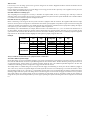
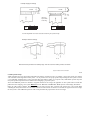
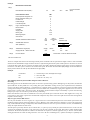
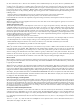
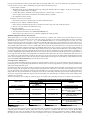
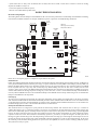
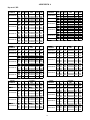
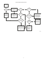
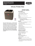
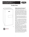
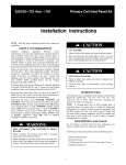
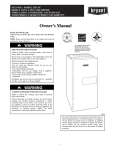
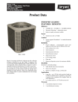
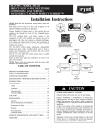
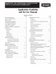
Evolution Zoning Design Guide
Design Guide
INTRODUCTION
The Evolution Zoning System provides the ability to control 2, 4, or 8 zones in a residential or light commercial application. Each constructed
zone should support the minimum airflow of the equipment selected. Consult the product data to determine minimum airflow requirements.
The Evolution Zoning System can only be used with variable speed furnaces, such as the 355AAV, 355CAV, or 315AAV, or with the FE fan
coil. To achieve the best operating and comfort it is recommended that the two stage compressor units, such as the 180ANA, 187ANA,
286ANA or the 288ANA be selected in the design of the zoning system. The multiple stage condensing units provide some leeway in the
system minimum airflow requirements.
Evolution Zoning incorporates cutting edge technology that sets it apart from any other zoning system on the market today. It contains all the
features of Zone Perfect Plus plus many improvements which make it the easiest system on the market to install and use with confidence:
S It does not require a bypass damper or leaving air temperature sensor, yet the HVAC equipment is always protected from limit trips and coil
freezing.
S It does not require a separate field installed power transformer.
S System can handle up to five dampers per zone.
S Evolution Zoning automatically identifies all communicating installed equipment.
S Patented Automatic Duct Assessment ensures that Evolution Zoning delivers superior and quiet comfort with any reasonable duct system.
S All temperature sensors and dampers remain the same as Zone Perfect Plus. All other components are new and are not interchangeable with
ZPP.
ZONING
DESCRIPTION
SYSTXBBUIZ01
Evolution Zone Control
Zoning
SYSTXBBSMS01
Smart Sensor
Zoning
SYSTXBB4ZC01
Damper Control Module
Zoning
SYSTXBBRRS01
Remote Room Sensor
RRS
EVOLUTION SYSTEM COMPONENTS
The Evolution System uses a serial communication bus to pass information between major system components. 24 vac control signals are
gone (with the exception of driving dampers and conventional outdoor units). This means that Evolution Zoning will use Evolution
compatible components only. A system will consist of:
S An Evolution furnace or fan coil (355, 315 furnaces, FE4 fan coil)
S An Evolution or new Preferred Series AC or HP
S Hybrid Heat – Evolution furnace with Evolution or new Preferred Series HP
S Evolution furnace with conventional single stage AC or FE fan coil with conventional AC or HP
S An Evolution Zoning User Interface (SYSTXBBUIZ01)
S One or two Evolution Damper Control Modules (SYSTXBB4ZC01)
S Remote Room Sensors (ZONEBB0RRS01) or Smart Sensors (SYSTXBBSMS01)
S Modulating dampers (DAMPREC, DAMPRND, DAMPSL)
Following is a brief description of each of these components.
Bryant Evolution Variable Speed 80 or 90% furnace or FE fan coil:
The Evolution System is a fully communicating control system. Only series 170 and later 90% Bryant variable speed furnaces, 80% 315AAV
or FE fan coils are acceptable indoor units that work with the Evolution System. Communication takes place over a four wire ABCD
communication bus.
The Evolution FE fan coils will operate with any Evolution or new Preferred AC or HP or any conventional single stage AC or HP. The
Evolution furnaces will operate with any Evolution, or Preferred AC or HP or any conventional single stage AC.
Evolution Zoning User Interface:
If the variable speed furnace or fan coil could be considered the heart of the system then the Zoning User Interface must be considered the
brain. It is the user access into the Evolution Zone System. It allows the user to operate, program, setup, monitor, and troubleshoot the system.
From the user interface, the program schedules and desired setpoints, fan speeds, and a number of other selections can be set for each
individual zone. It will also notify the homeowner of any maintenance reminders or problems in the system.
The Evolution Zoning User Interface (SYSTXBBUIZ01) is not the same as the standard Evolution User Interface. Only the Evolution
Zoning User Interface contains the necessary programs and algorithms needed to operate the Zone System.
The standard Evolution User Interface (SYSTXBBUID01) will not work with zoned systems. However you can use the Zoning User
Interface in single zone applications by going into the service screens and turning off zoning.
Evolution Damper Control Module:
The Damper Control Module receives signals from the Zoning User Interface and then turns on the equipment and modulates the necessary
dampers to maintain space temperature. All components are connected directly to the Damper Control Module. One Damper Control Module
will serve up to four zones. If more than four zones exist, a second damper control module is added to the system to allow for up to eight
zones.
Remote Room Sensors:
The Zoning User interface serves several different purposes. Along with its control of the system it is also the default temperature and
humidity sensor for zone one. If needed this Zoning User Interface can be installed in a remote location with a Remote Room Sensor or a
Smart Sensor in the Zone 1 space. However in this situation the Zoning User Interface will still need to be located where it will accurately
sense space humidity as the humidity sensor cannot be remotely located.
All other zones will need a Remote Room Sensor or a Smart Sensor to allow the User Interface to know the temperature in each of its zones.
You can mix Remote Room Sensors and Smart Sensors in a system.
Remote Room Sensors are two wire sensors that are home run back to the Evolution Damper Control Module. However, it is always
recommended to run at least four wires for possible future installation of Smart Sensors.
The design requirement for the Evolution Zoning system does not require the installation of a bypass damper, leaving air temperature sensor
(LAT), or a heat pump sensor (HPT). The outdoor sensor is installed on all Evolution compatible equipment and will not require an additional
installation of an outdoor temperature (OAT) unless Evolution compatible equipment is not use. The use of a barometric bypass damper or a
dump zone without a damper will cause erratic operation of the zoning system and create comfort control issues.
Smart Sensors:
Optional Smart Sensors are available to take the place of standard Remote Room Sensors. Smart Sensors will display zone temperatures and
allow the user to change zone setpoints from within the room instead of returning to the main Zone User Interface. Smart Sensors tie into the
systems four wire communication buss (ABCD terminals) and can be daisy chained / t--tapped / wire--nutted to any point or device on the
communication bus (ABCD terminals).
Modulating Dampers:
Bryant’s dampers are of the modulating type and come in various sizes. They are powered open, and powered closed using a 24 vac three
wire connection and are modulated to maintain space temperature.
The dampers are non spring return and have specific drive timing allowing the system to track the dampers position. Because of this, non
Bryant dampers may not be substituted.
Changes were recently made to these dampers allowing them to draw less current than older dampers allowing up to five dampers to be
connected to a single zone output – while allowing the equipment transformer to still provide all power. The Zoning Control module only
cycles one zone at a time thus minimizing the load on the system transformer.
PLANNING THE INSTALLATION
Selecting Zones
Usage: Group together rooms that have similar usage, occupancy, and heat load.
Levels: Different levels in a home need to be separate zones. Each level may be further divided into zones.
Comfort vs. energy saving: If energy saving is an objective, areas which will be unoccupied at different times need to be separated so they
can selectively be setback. If maximum comfort is desired, areas with different heat loss/gain as well as different levels need to be separated.
Zones in which different comfort temperatures are desired also need to be separated.
Existing ductwork: If the installation is a retrofit, the existing duct system may limit zone selection options.
Multiple dampers: Up to five dampers may be used in a zone by electrically connecting them in parallel. Multi--damper enablers are not
needed.
Damper types: Round, rectangular, or rectangular slip--in dampers may be intermixed in any arrangement.
Two capacity equipment: All Evolution furnaces (355, 315) have two heating stages. ACs and HPs may be either single or two stages. If
more than four zones are desired, a two stage compressor is recommended to be able to quietly supply reduced capacity to calls from smaller
zones.
How does Evolution Control the Zones?
The Evolution’s sophisticated algorithms were constructed to maintain comfort to the occupants by continuously monitoring each zone’s
temperature to satisfy the comfort conditions. If a zone cannot handle the minimum equipment cfm the Evolution Control will find a zone that
is slightly out from the setpoint and open the damper to allow the system to run. If none of the zones are away from the setpoint the Evolution
Control looks for unoccupied zones or setback zones to allow the system to run to satisfy the original zone caller.
Zones that do not handle minimum equipment airflow will cause other zones to be heated or cooled above or below their setpoint
temperatures. If this is an acceptable alternative then the undersized zones will not present any major issues. In most circumstances this is not
an acceptable situation and the only way to relieve this to make sure each zone handles the minimum airflow of the installed equipment.
Remember the Evolution System tries to satisfy all zones simultaneously so it is common for zones to open incrementally to satisfy the
comfort points.
Ductwork and variable speed ECM indoor blower motors
The variable speed ECM indoor blower motor has changed many of the aspects of designing the ductwork system. In many circumstances the
ECM variable speed motor provides better airflow in marginal duct systems however, if proper techniques are not used, they can also create
issues that are not easily corrected after installation.
2
Where to start:
It is necessary to start the design process with a good heat loss/gain of the structure. Equipment should be selected that matches the heat
loss/gain to maintain the best comfort.
From an efficiency standpoint, bigger is not better. Bigger wastes energy, shortens the life expectancy of the equipment and may leave the
customer feeling uncomfortable in the process.
Determine airflow for each living space
After completing the heat loss/gain it is necessary to determine the required airflow, in cfm, to each living space. This step is crucial in
delivering comfort to the customer and is necessary to design an efficient duct system. The duct system should deliver the calculated airflows
to each zone in order to maintain temperature throughout the home.
Determine the necessary equipment
Before concentrating on the design of the duct system a selection of equipment must be conducted. The equipment will dictate the design
criteria for the duct system. It is important to remember that with variable speed equipment it is possible to require more cfm for heating than
cooling. The variable speed equipment is very flexible in match--ups with outside air conditioner and heat pump units requiring the designer
of the system to pay close attention to each piece of equipment’s airflow requirements.
The flexibility of the 355AAV060120, for example, allows the furnace to be matched with a 2, 3, 4, or 5 ton outdoor unit. If matched to a 2
ton unit requiring 700 cfm for high stage operation, and the furnace high stage operation requires 1530 cfm, it is easy to see that the duct
system must be able to handle 1530 cfm. If the duct work were sized to the condensing unit the furnace would likely experience high limit
trips and lock out. The underlined numbers highlight the cfm required to properly design the duct work.
Example:
Furnace
355AAV060120
315AAV048090
Low
High
2---Stage Unit
Low
High
890
1530
187ANA024
525
700
890
1530
187ANA036
700
1050
890
1530
187ANA048
875
1400
890
1530
187ANA060
1225
1750
985
1210
187ANA024
525
700
985
1210
187ANA036
700
1050
985
1210
187ANA048
875
1400
Always consult the Product Data for the equipment under consideration.
The Airflow killer: Equivalent length
Not all duct fittings are created equal. When designing a duct system it is beneficial to use fittings that provide less resistance to airflow. In
most units the initial takeoffs can add more equivalent length than the duct calculator allows. All duct calculators provide proper sized duct to
an equivalent length of 100 feet. Either a less resistive duct fitting should be used or the additional equivalent length has to be taken into
consideration. If the fittings cannot be changed then a bigger size duct must be selected.
The example below is a common fitting seen on most job sites. The supply and return fitting are already over the duct calculators, (supply air
120 + return air 55), 100 foot of equivalent length and would require the duct work to be extremely large to overcome the resistance. On the
right the fittings, (supply air 35 + return air 35 = 70 feet of TEL), provides only 35 foot of equivalent allow the designer a little freedom in the
remaining design of the duct system. If the fittings shown in the left images were used on both the supply and return side of the system the
duct system would be 175 equivalent length of duct not considering any other length of duct or other fittings. Using the duct calculator to
design the duct system in this example would not provide a proper operating duct system if the fitting losses are not recognized and accounted
for.
3
Example: Supply Air Fittings
H/W is the
Aspect Ratio
of the fitting.
BULL
HEAD
H/W
0.5
1.0
EL
120
85
TAPERED
HEAD
H/W
0.5
1.0
EL
35
25
The H/W Height/Width ratio must be calculated to determing EL equivalent length.
Example: Return Air Fittings
EL = 55
EL = 35
Note that the drop connection is relatively large. This was a common lowboy furnace connection.
Figures and Tables from ACCA Manual D
A00138
Consider pressure drops:
“Rules of thumb” have been adopted that could mislead the designer to believe that they are designing a proper duct system. One common
“rule of thumb” used throughout the industry is that .1 or .08 per 100 foot are the proper pressure drops to design the duct system to. This is
a very misleading assumption due to system accessories like: high efficiency filters, wet evaporator coils, outlet diffuser pressure drops and
many other pressure drops that must be considered when designing a proper duct system.
ACCA and SMACNA produce the industries’ recognized standards for the design and application of duct systems. Please consult their
publications when designing a duct system. Reference: ACCA “Manual D” and SMACNA “HVAC Systems -- Duct Design, 4th Edition”.
Return air grills, registers, diffusers, filters, furnace coils, and other necessary duct accessories add pressure drop to the system. When
calculating the duct system friction rate each of these external accessories must be accounted for to determine the proper friction rate to design
the duct system to. ACCA Manual D presents a table to help determine the proper friction rate for duct design.
4
Example:
Manufacturer’s Blower Data
Step 1)
External Static Pressure (ESP)=
Step 2)
0.6
IWC
Device Pressure Losses
IWC
Direct expansion refrigerant coil
0.27
Electric resistance heating coil
0
Hot water coil
0
Heat Exchanger
0
Low efficiency filter
0
High or mid-efficiency filter
0
Electronic filter
0
Humidifier
cfm=
1200
From Product Data
(PDD)
0
Supply outlet
0.03
Return grille
0.03
Balancing damper
0.03
Other device
Available Total External Static Pressure
Step 3)
Total Effective Length (TEL)
0.6
0.36
Supply
Supply-side TEL + Return-side TEL=
Step 5)
Sum of
Component
PD
Pressure
Difference (Pd)
Available Static Pressure
ASP=(ESP-DPL)=
Step 4)
PD
from
PPD
FR=Pd*100/TEL
Return
200
0.060
0.24
IWC
TEL
200
400
Feet
Friction Rate = Pressure difference*100/TEL
Table from ACCA Manual D
The above example shows that the unit duct design currently under consideration has an equivalent duct length of 400 feet. ACCA uses TEL
which stands for Total Effective Length and means the same as equivalent length. This duct system would require that .06 friction rate be used
to design the duct system. The wet evaporator coil, supply outlet, return grille, and balancing damper pressure drops are used to calculate the
friction rate of the duct system to select the duct work for this system. To calculate the Friction Rate (FR) multiply the Pressure Difference
(Pd) by 100 then divide the result by the Total Effective Length (TEL).
Example:
Friction Rate
=
Pressure Drop X 100 / Total Equivalent Length
FR
=
Pd X 100 / TEL
FR
=
(.24 X 100 = 24 / 400) = .06
The remaining ductwork system should be designed around a FR of .06.
Duct sizing
Duct sizing practices for the Evolution Zone System are the same as previous zoning systems. Although larger is always better, the Evolution
System will make the best possible use of any existing duct system. If Evolution is being forced by load requirements and/or small ducts
toward a point where a limit would trip or a coil would freeze, it will take actions to avoid these events. These actions can include partially
opening selected dampers, reducing system airflow to its lowest reliable level, and ultimately staging down equipment. There is no need to
balance ducts as required with a non--zoned system. The Evolution System modulates dampers automatically to provide duct balancing.
Dampers open only as far as needed to provide necessary conditioning.
Return ducts: Returns in each zone are desirable but not necessary if reasonable space exists under doors to allow supplied air to escape. It is
good practice to place returns at points where uncomfortable temperatures may collect. Low levels to pull cold air from floors and high levels
to pull hot air from ceilings.
Why no bypass, LAT, or HPT sensors?
Not only does Evolution not need a bypass, but a bypass must not be used. Evolution Systems have both variable speed blowers and
modulating dampers. Bryant patented algorithms are used to: Maintain a safe airflow through the equipment to prevent coil freezing, limit
trips, and uncomfortable leaving air temperatures, limit maximum airflow into each zone to prevent excessive air noise, and simultaneously
satisfy the setpoint demands of all the zones.
At initial power up and daily thereafter (at user selected time, or 1 pm every day by default), the system measures the size of each zone duct
and learns the maximum cfm capacity of each zone based on its size and an installer set noise limit. This feature is called Automatic Duct
Assessment. The Evolution System also calculates the minimum cfm required to maintain equipment safety at all times. The Evolution
Zoning System knows the actual cfm being delivered to each zone at all times. Combining these, it positions all dampers to optimally meet
5
the three requirements above. If all three above conditions cannot be simultaneously met by the system, then the system will invoke a
patented dynamic algorithm sequence. This includes using the variable speed blower to reduce total system airflow to a safe minimum,
cracking open the zone dampers in a controlled manner to bleed excess air first into unoccupied zones and then into setback zones while
preventing over--conditioning of these zones. Evolution System does not require a leaving air temperature sensor primarily because there is no
bypassed air to affect leaving air temperature. Minimum airflow is always maintained through the system to guarantee system acceptable
leaving air temperatures to aid in preventing limit trips. Typical zoning systems with conventional blowers require LAT monitoring for the
following reasons:
S The bypass dumps too much conditioned air back into the equipment return causing excessive leaving air temperature.
S System air flow cannot be maintained due to high static pressure, and low air flow can cause excessive LAT.
If an Evolution blower cannot deliver the required cfm, it signals the Zoning User Interface, which responds to reduce the static pressure.
Equipment sizing
When selecting heating and cooling equipment select the sizes, use the same rules as for un--zoned equipment. In general, do not oversize or
undersize equipment due to zoning.
Airflow and temperature control
The Evolution System measures the actual temperature in each zone to 1/16 degree and responds to these very small changes. The system
continually calculates how far each zone is away from its setpoint to an accuracy of 1/16 degree. Most other zoning systems only know
whether a zone is above or below its setpoint but not how far off it is from setpoint or how long it has been away from setpoint. Evolution
System uses a proportional integral algorithm to maintain zone temperatures. Evolution dampers continuously modulate to any position
between fully open and closed rather than only being just open or closed. With these unique capabilities, the patented algorithms have been
designed to simultaneously keep all zone temperatures within .5 degree of their setpoints. The following is a list of exceptions that can cause
the zones to not maintain temperature setpoints.
S When the equipment runs out of capacity to carry the total load.
S Zones in close proximity to each other cannot be made to hold significantly different temperatures, even with dampers fully open or closed.
S A setback temperature in a zone that is too high in cooling or too low in heating when the rest of the zones have comfort settings.
S When the installer, using the User Interface service screens, sets the zone to a low air flow limit to maintain very low noise levels.
(Example: A zone set to low airflow may not be able to reach comfort setpoints.
Zoning duct assessment
With (--A) and earlier models, the system will perform a duct assessment every 24 hours at 1 PM in order to determine the relative size of
every zone. The time is not adjustable. With (--B) models, the duct assessment time is selectable to any hour of the day or night. The duct
assessment will take approximately 1--1/2 minutes per zone to complete. The system will first open all zones and drive the blower to 175
cfm/ton of cooling (or the minimum indoor unit’s airflow, whichever is greater). It will then take a static pressure measurement. The system
will then close all zones and open one zone at a time, taking a static pressure measurement for each zone. The system will then close all zones
and take a pressure measurement, getting a value for the duct leakage up to and through the dampers. With these static pressure
measurements, the system will calculate the relative size of each zone as well as the percent leakage through the dampers.
Blower Cutback
Blower cutback is a feature in the User Interface that is designed to protect the indoor unit from extremely high static pressure situations. The
process begins when the indoor blower motor sets a cutback “flag” which tells the UI the RPM is at the maximum allowed by the motor. This
is typically around 1300 RPM.
Zoned System Cutback
When the motor sets a cutback flag, the requested cfm begins to back down in 50 cfm increments. This will be seen in the furnace or fan coil
Status screens. The cfm request is reduced until either the indoor motor removes the cutback flag (RPM is sufficiently reduced), or the airflow
request is at the minimum allowed. If minimum airflow is requested before the cutback flag is removed, the system will attempt to dump air
using the same method as Airflow Limiting (stage down, dump to unoccupied zones, adjust setpoints etc.). If the cutback flag is still active
after dumping, the system will shut down and set an EXCESS STATIC PRESSURE fault in the Last 10 System Events. The system will start
again when more zones call for conditioning, and airflow restrictions no longer exist. During cutback on original and (--A) models, the Static
Pressure displayed in the Service Screens is not valid since the unit cannot deliver the requested airflow. With (--B) models, UNKNOWN will
be displayed for Static Pressure while blower cutback is active.
Zoned System Staging – Normal Operation
Each zone’s temperature is continually measured to within 1/16 degree. When any zone’s demand is greater than 0.8 degree or the average of
all zone demands is greater than 0.5 degree, the equipment is turned on or staged up one stage if it is already on. When the average demand of
all zones is zero, the equipment turns off or stages down. This provides temperature control in all controlled zones within less than one degree
of setpoint. Note that when a damper is closed, its zone is satisfied. If other zones still have demands, the equipment will continue to run and
this closed zone may become over conditioned due to air crossing over from other zones. Under these conditions, zone temperatures cannot
be controlled accurately in the affected zones.
Zoning Airflow Limits and Equipment Protection
The maximum airflow allowed into a zone is based on the relative size of the zone determined by the duct assessment, and the airflow limits
selected for each zone. Airflow limits are set to high as factory default. The following equation shows how a zone’s maximum airflow is
determined. The default airflow limit of high is 2.0, or 200%. (450 cfm)(# nominal tons)(airflow limit)(Zone % +leak %) Example: if a zone
is determined to be 25% of the entire system and the leakage is 15% with a 5 ton condenser and a 100--20 furnace. Use the greater of (450) x
(5) = 2250 or high heat airflow which, in this case, is 1510 cfm. If the condenser was a 3 ton, 450 x 3 = 1350, and high heat airflow would be
used instead.
450 x 5 x 2.0 x (.25 + .15) = 1800 cfm. This airflow multiplier limit can be adjusted to reduce or increase allowable noise levels; Low =
100%, Med = 150%, High = 200%, Max = 210%
6
If the system determines that with the selected airflow limit, the allowable airflow into a zone is not sufficient for the equipment to operate
correctly, and that zone has a call for conditioning, the system will take the following 4 steps:
1. Reduce airflow if possible
a. Minimum of 275 cfm per ton minimum in high stage cooling (325 if Dehum airflow set to High). 175 cfm per ton in low stage
cooling. (225 if Dehum airflow set to High)
b. Comfort Heat airflow is minimum for heat pump heating (3.5 x outdoor temp + 137) cfm /ton
c. Use heat pump comfort airflow as minimum if AC airflow is efficiency or MAX
d. No adjustment for furnace heating
2. Dump air to zones set to Unoccupied
a. Unoccupied zones may be conditioned up to the most conditioned setpoint.
3. Dump air to zones with less conditioned setpoints
a. Zones with less conditioned setpoints may be conditioned to within 3 deg of the most conditioned setpoint.
b. Increase or decrease all zones an additional 0.75 deg
4. Stage down equipment
a. Equipment will stage down or shut off if necessary
b. Last 10 System Events will record an AIRFLOW LIMITED event
c. If shut down occurs, other zones need to call before equipment will resume operation
Minimum Equipment Airflows in Zoned Systems
When airflow limits are set to Max, the maximum airflow allowed into a particular zone is 210% of the assessed airflow for that zone.
Example: If a zone size is determined to be 25% of the entire system, the leakage is 15% and the maximum airflow is 2250 => [(450)(5)].
Airflow into this zone is 450 x 5 x 1.5 x (.25 + .15) = 1350 cfm. Minimum airflow for a t ton system in high stage is 275 cfm / ton = 1375
cfm. The zoning system uses the chart below to determine the minimum airflow that must be achievable before the system will turn on or
continue to run. Using the previous example, in cooling, a 2--stage 5 ton system’s minimum airflow per the chart is 275 cfm / ton (1375 cfm).
The maximum airflow allowed into a zone set to MAX airflow limit is 1050 cfm. The system will not turn on in high stage because this is
below the minimum airflow required for high stage. The minimum airflow for low stage is 175 cfm / ton (875 cfm). The system will turn on
in low stage and attempt to run full low stage airflow. This will depend on the type of outdoor unit installed and the current humidity demand.
A typical 2--stage Bristol compressor system will run about 220 cfm / ton when set to efficiency low stage airflow which is 1100 cfm for a 5
ton. This is slightly higher than maximum allowed into the zone, but well above the minimum for reliable operation. The system will turn on
in low stage and reduce the airflow to 1050 cfm which is the maximum airflow allowed into that zone set at MAX airflow limit. If the zone is
very restrictive the system will attempt to dump air into other zones per the steps shown in the Airflow Limits and Equipment Protection
section above (beginning with step 2 since this is already the minimum airflow). If all steps are unsuccessful, the system will shut down and
register an EXCESS STATIC PRESSURE event in the last 10 system events.
Unoccupied zones / Setback zones
If any zones within the building will not be occupied, it is highly desirable to put the zone in the Unoccupied setting. Unoccupied can be
permanently set for a zone by pressing the Hold button for three seconds. It can also be programmed for a period by pressing the Hold button
while in the Program Schedule screen.
Unoccupied zones may be used by the system as a dump zone. If the system determines that it will supply too much air into the zones with
demand, it will open the unoccupied zone’s damper until the unoccupied zone’s temperature is equal to the most demanding zone’s set temp.
Once the Unoccupied zone’s temperature reaches the most demanding zone’s set temp, dumping of air will stop and the Unoccupied zone’s
damper will close. The system will then start to dump into zones that are setback farther than three degrees from the demanding zone. If the
setback zone’s temperature is within three degrees of the most demanding zone, then dumping of air will stop and the system will stage down
equipment, or even turn off.
The use of Unoccupied zones can help the system run longer, and can help satisfy demanding zones that are too small to run by themselves.
APPLICATION
Furnace + Air Conditioner
Hybrid Heat
Heat Pump + Fan Coil + Electric Heat
Furnace Only
Heat Pump + Fan Coil + Hot Water
Coil
Fan Coil + Hot Water Coil
MINIMUM AIR FLOW PER ZONE TO KEEP SYSTEM RUNNING
COOLING
HIGH STAGE / SINGLE
HEATING
LOW STAGE
STAGE
275 /325 cfm / ton
--Low Stage furnace Airflow
Above heat pump Lockout: Comfort
heat pump Heating Airflow
275 /325 cfm / ton
175 / 225 cfm / ton
Below heat pump Lockout: Low Stage
furnace Airflow
Comfort heat pump Heating Airflow or
Efficiency heat pump airflow depend275 /325 cfm / ton
175 / 225 cfm / ton
ing on airflow setting
----Low Stage furnace Airflow
Comfort heat pump Heating airflow or
Efficiency heat pump Airflow depend275 /325 cfm / ton
175 / 225 cfm / ton
ing on airflow setting
275 /325 cfm / ton
175 / 225 cfm / ton
Hot Water heating selected airflow
Air flow summary
The variable speed blower and the damper control algorithms work in conjunction to automatically maintain safe airflow levels through the
equipment under all conditions. Also, the airflow into any zone is limited to a maximum value. This value is set (Low, Medium High,
Maximum) for each zone by the installer in the Zone User Interface install/service screens. The default factory setting is “HIGH”. The higher
this setting, the more air can be delivered into a zone. Unoccupied zones are used in a controlled manner to receive excess air when needed. In
7
a system where there are many zones of different sizes and loads, ducts that are small or when there is evidence of zones not meeting
setpoints, the installer’s remedy is to:
S Create unoccupied zones within the system
S Increase zone airflow limits in problem zones.
DOING THE INSTALLATION
Review the wiring diagram
The drawing below shows the Damper Control Module and all of its connection points. Please consult Damper Control Module and Zoning
User Interface installation instructions for in--depth installation, sequence of operations and troubleshooting information.
2-spd
Outdoor
Unit
Ventilator
Unit
Indoor
Unit
A B C D
Optional
Leaving Air & Heat Pump
Temperature Sensor
YRGB
A B C D
LAT COM HPT
ZS1
ZS1C
FUSE
CLS1
COM1
CPN1
Zone - 1 Sensor
(optional)
DIP Switch
ZS2
ZS2C
Zone - 2 Sensor
ZS3
ZS3C
CLS3
COM3
CPN3
Zone - 3 Sensor
Status
CLS4
COM4
CPN4
ON
OFF
1 2
CLS2
COM2
CPN2
Comm
Damper Control Module, Zones 1-4
ZS4
ZS4C
Zone - 4 Sensor
A00140
Please refer to current price pages for a complete list of part numbers and options.
Install and wire
Follow the installation Instructions supplied with the Zone Control, Smart Sensors, Remote Room Sensors, Damper Control, and Dampers to
do the physical installation. Because of its low power usage, no separate transformer is needed (ONLY 5 Zone dampers per Zone). Mark each
Damper and Remote Room Sensor wire at the Damper Control end so they do not become mixed up. Any connection format for the ABCD
bus is acceptable: home run, t--taps, daisy chain or multi drop loop. When installing more than one wire under a terminal, twist the wires
together to ensure proper contact in the ABCD terminal block. Seal behind the Zone Control and any Smart Sensors or RRS’s to prevent air
currents within walls from affecting temperature readings. If you have more than 4 zones a second Evolution Damper Control Module is
necessary. Wire the ABCD connection to the first Evolution Damper Control Module and turn the dip switch setting on the second Evolution
Damper Control Module to the ON position.
Powering up
At power up, the system will proceed through its normal auto configuration process, finding and adapting itself to the indoor and outdoor
units. All zones with Remote Room Sensors will automatically be learned. Zones with Smart Sensors will need to have zone numbers entered
at each Smart Sensor. The Zone Control will inform you of this if needed. Use Smart Sensor Installation Instructions to set zone numbers. An
Evolution Zoning System can have a mix of Remote Room Sensors or Smart Sensors.
Startup and automatic duct assessment
After all Smart Sensors are assigned, the system performs an initial startup automatic duct assessment that can take up to 6 minutes to
complete The blower is run at a constant low airflow of 175 cfm per ton (equipment is off) with all ducts closed (to measure leakage), then
with each zone individually opened, and finally with all zones open. In each case the static pressure is measured using a patented algorithm
based on the speed of the blower motor and other characteristics. From these static pressure measurements, the system computes the relative
capacities of each zone’s ducts. This assessment is automatically repeated at 1 pm each day to adjust for changes in the duct system due to
blockage of registers and filter usage. Note: The damper leakage measured is the air leakage up to and through the closed dampers. It does not
measure duct leakage after the dampers. The system automatically adjusts the algorithms to account for the measured leakage. At the end of
this automatic process, Evolution Zoning System shows you the exact cfm capabilities of each zone and the air leakage (cfm) in the system.
The system is then ready to operate.
8
Brief summary
1. Heat loss / gain
2. Cfm per room
3. Select equipment
a. With variable speed pay close attention to high heat cfm VS. high cooling cfm.
b. Use the equipment Product Data to determine cfm
4. Calculate equivalent length of longest duct runs.
a. Use duct fittings that have low equivalent lengths.
5. Calculate duct system Friction Rate
a. Pressure drops
(1.) Wet evaporator coils
(2.) Supply outlet
(3.) Return grille
(4.) Balancing dampers
(5.) Any accessories
(a.) Humidifiers
(b.) Electronic air cleaner
(c.) Pleated filters
(d.) High efficiency filters.
6. Design Duct System using the Friction Rate calculated in step 5.
9
ADDENDUM A
Bryant AC/HP
355AAV
FURNACE
355AAV042040
355AAV042060
355AAV042080
355AAV060080
355AAV060100
355AAV060120
355AAV
FURNACE
355AAV042040
355AAV042060
355AAV042080
355AAV060080
355AAV060100
355AAV060120
355CAV
FURNACE
355CAV042060
355CAV042080
355CAV060080
355CAV060100
355CAV060120
LOW MED HIGH
540
540
500
500
720
720
705
705
705
705
890
890
890
890
1200
1200
1200
1200
NA
NA
NA
NA
NA
NA
NA
NA
NA
NA
NA
NA
NA
NA
NA
NA
NA
NA
785
785
1070
1070
1490
1490
1530
1530
1530
1530
1530
1530
1530
1530
1900
1900
1900
1900
LOW MED HIGH
540
540
500
500
720
720
705
705
705
705
890
890
890
890
1200
1200
1200
1200
NA
NA
NA
NA
NA
NA
NA
NA
NA
NA
NA
NA
NA
NA
NA
NA
NA
NA
785
785
1070
1070
1490
1490
1530
1530
1530
1530
1530
1530
1530
1530
1900
1900
1900
1900
LOW MED HIGH
410
410
540
540
525
525
525
525
660
660
660
660
890
890
890
890
560
560
710
710
705
705
705
705
890
890
890
890
1130
1130
1130
1130
1070
1070
1220
1220
1470
1470
1470
1470
1510
1510
1510
1510
1900
1900
1900
1900
2---STAGE
HIGH LOW
UNIT
187ANA024 700
525
187ANA036 1050 700
187ANA024 700
525
187ANA036 1050 700
187ANA024 700
525
187ANA036 1050 700
187ANA024 700
525
187ANA036 1050 700
187ANA048 1400 875
187ANA060 1750 1225
187ANA024 700
525
187ANA036 1050 700
187ANA048 1400 875
187ANA060 1750 1225
187ANA024 700
525
187ANA036 1050 700
187ANA048 1400 875
187ANA060 1750 1225
2---STAGE
HIGH LOW
UNIT
180ANA024 800
800
180ANA036 1200 925
180ANA024 800
800
180ANA036 1200 925
180ANA024 800
800
180ANA036 1200 925
180ANA024 800
800
180ANA036 1200 925
180ANA048 1400 1120
180ANA060 1750 1400
180ANA024 800
800
180ANA036 1200 925
180ANA048 1400 1120
180ANA060 1750 1400
180ANA024 800
800
180ANA036 1200 925
180ANA048 1400 1120
180ANA060 1750 1400
2---STAGE
HIGH LOW
UNIT
187ANA024 700
525
187ANA036 1050 700
187ANA024 700
525
187ANA036 1050 700
187ANA024 700
525
187ANA036 1050 700
187ANA048 1400 875
187ANA060 1750 1225
187ANA024 700
525
187ANA036 1050 700
187ANA048 1400 875
187ANA060 1750 1225
187ANA024 700
525
187ANA024 1050 700
187ANA024 1400 875
187ANA024 1750 1225
355CAV
FURNACE
355CAV042060
355CAV042080
355CAV060080
355CAV060100
355CAV060120
355CAV060120
315AAV
FURNACE
315AAV036070
315AAV048090
315AAV060110
315AAV066135
315AAV066155
315AAV
FURNACE
315AAV036070
315AAV048090
315AAV048090
315AAV066135
315AAV066155
10
LOW MED HIGH
410
410
540
540
525
525
525
525
660
660
660
660
890
890
890
890
560
560
710
710
705
705
705
705
890
890
890
890
1130
1130
1130
1130
1070
1070
1220
1220
1470
1470
1470
1470
1510
1510
1510
1510
1900
1900
1900
1900
LOW MED HIGH
735
735
985
985
985
1320
1320
1320
1320
1700
1700
1700
1700
1715
1715
1715
1715
NA
NA
NA
NA
NA
NA
NA
NA
NA
NA
NA
NA
NA
NA
NA
NA
NA
1180
1180
1210
1210
1210
1475
1475
1475
1475
1915
1915
1915
1915
1970
1970
1970
1970
LOW MED HIGH
735
735
985
985
985
1320
1320
1320
1320
1700
1700
1700
1700
1715
1715
1715
1715
NA
NA
NA
NA
NA
NA
NA
NA
NA
NA
NA
NA
NA
NA
NA
NA
NA
1180
1180
1210
1210
1210
1475
1475
1475
1475
1915
1915
1915
1915
1970
1970
1970
1970
2---STAGE
HIGH LOW
UNIT
180ANA024 800
800
180ANA036 1200 925
180ANA024 800
800
180ANA036 1200 925
180ANA024 800
800
180ANA036 1200 925
180ANA048 1400 1120
180ANA060 1750 1400
180ANA024 800
800
180ANA036 1200 925
180ANA048 1400 1120
180ANA060 1750 1400
180ANA024 800
800
180ANA036 1200 925
180ANA048 1400 1120
180ANA060 1750 1400
2---STAGE
UNIT
187ANA024
187ANA036
187ANA024
187ANA036
187ANA048
187ANA024
187ANA036
187ANA048
187ANA060
187ANA024
187ANA036
187ANA048
187ANA060
187ANA024
187ANA036
187ANA048
187ANA060
2---STAGE
UNIT
180ANA024
180ANA036
180ANA024
180ANA036
180ANA048
180ANA024
180ANA036
180ANA048
180ANA060
180ANA024
180ANA036
180ANA048
180ANA060
180ANA024
180ANA036
180ANA048
180ANA060
HIGH LOW
700
1050
700
1050
1400
700
1050
1400
1750
700
1050
1400
1750
700
1050
1400
1750
525
700
525
700
875
525
700
875
1225
525
700
875
1225
525
700
875
1225
HIGH LOW
800
1200
800
1200
1400
800
1200
1400
1750
800
1200
1400
1750
800
1200
1400
1750
800
925
800
925
1120
800
925
1120
1400
800
925
1120
1400
800
925
1120
1400
System Design Parameter Decisions
How many zones
are needed?
Greater than
Two Zones?
Is there any one zone that
will require a great deal of
conditioning when the other
zones do not?
Yes
No
Yes
Each zone should
be able to carry
the miniumu unit
air flow for periods
of time at the
desired ground
level.
Most occupied zone must be
able to carry minimum unit
air flow at the desired sound
level.
This zone should have its
own return air duct.
No
Greater than
Four Zone?
Yes
Are there any
unoccupied zones?
Yes
No
No
Are there any
unoccupied zones?
Can one or more zones
be scheduled to be
unoccupied?
Yes
No
Each zone should be able to
carry minimum unit air flow at the
desired sound level minus
maximum cfm that can be
pushed through unoccupied
zones minus duct leakage in
50% of the zones.
No
No
Can one or more zones
be scheduled to be
unoccupied?
Yes
Is comfort more
important than
sound level?
No
Each zone should be
designed to carry the
design air flow for the
largest zone at the
desired sound level.
Yes
Yes
Each zone should be able to
carry minimum unit air flow at the
desired sound level minus
maximum cfm that can be
pushed through unoccupied
zones.
Each zone should be
designed to carry the
design air flow for the
largest zone
Regardless of the
desired sound leve.
A00139
11
E2010 Bryant Heating & Cooling Systems D 7310 W. Morris St. D Indianapolis, IN 46231
Printed in U.S.A.
Edition Date: 11/10
Manufacturer reserves the right to discontinue, or change at any time, specifications or designs without notice and without incurring obligations.
12
Catalog No. DGZONE ---01
Replaces: NEW