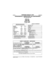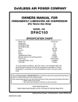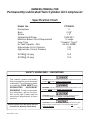
1
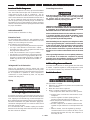
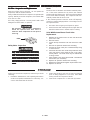
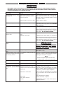
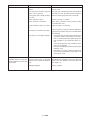
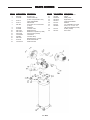
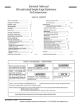
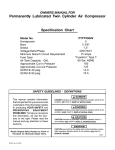
OWNERS MANUAL FOR Permanently Lubricated Twin Cylinder Air Compressor Specification Chart Model No. Horsepower Bore Stroke Voltage/Hertz/Phase Minimum Branch Circuit Requirement Fuse Type Air Tank Capacity - GAL Approximate Cut-in Pressure Approximate Cut-out Pressure FTV560V 5 2 3/8" 1.2" 220V/50/1 15 amps "Fusetron" Type T 60 Gal. ASME 100 125 14.0 10.5 SCFM @ 40 psig SCFM @ 90 psig SAFETY GUIDELINES - DEFINITIONS This manual contains information that is important for you to know and understand. This information relates to protecting YOUR SAFETY and PREVENTING EQUIPMENT PROBLEMS. To help you recognize this information, we use the symbols to the right. Please read the manual and pay attention to these sections. Retain Original Sales Receipt as Proof of Purchase for Warranty Repair Work. MGP-FTV560VA 9/14/99 DANGER indicates an imminently hazardous situation which, if not avoided, will result in death or serious injury. WARNING indicates a potentially hazardous situation which, if not avoided, could result in death of serious injury. CAUTION indicates a potentially hazardous situation which, if not avoided, may result in minor or moderate injury. CAUTION used without the safety alert symbol indicates a potentially hazardous situation which, if not avoided, may result in property damage. 10/2/97 TABLE OF CONTENTS SAFETY GUIDELINES ........................................................... 1 WARNING CHART ............................................................. 3-4 GLOSSARY .......................................................................... 5 DUTY CYCLE ......................................................................... 5 GENERAL INFORMATION ................................................... 5 ON-RECEIPT INSPECTION .................................................. 5 DESCRIPTION OF OPERATION ........................................... 6 INSTALLATION AND BREAK-IN PROCEDURES .................................................................... ....................................................................6-8 Removal of Shipping Boards and Installation ...................... 6 Location of Air Compressor .................................................... 7 Lubrication and Oil .................................................................. 7 Extension Cords ...................................................................... 7 Voltage and Current Protection .............................................. 7 Piping........................................................................................ 7 Grounding Instructions ........................................................... 7 Additional Regulators & Controls .......................................... 7 Break-in Procedures ................................................................ 7-8 OPERATING PROCEDURES ................................................. 8 Daily Start-up Checklist .......................................................... 8 MAINTENANCE ................................................................. 8-9 Air Filter - Inspection and Replacement .............................. 9 Safety Valve - Inspection ...................................................... 9 Motor ....................................................................................... 9 Check Valve Replacement .................................................... 9 STORAGE ........................................................................... 9 TROUBLESHOOTING GUIDE ........................................ 10-11 PARTS LISTING ..................................................................... 12-13 2 ENG IMPORTANT SAFETY INSTRUCTIONS • SAVE THESE INSTRUCTIONS • IMPROPER OPERATION OR MAINTENANCE OF THIS PRODUCT COULD RESULT IN SERIOUS INJURY AND PROPERTY DAMAGE. READ AND UNDERSTAND ALL WARNINGS AND OPERATING INSTRUCTIONS BEFORE USING THIS EQUIPMENT. HAZARD RISK OF BURSTING HOW TO PREVENT IT WHAT CAN HAPPEN AIR TANK THE FOLLOWING CONDITIONS COULD LEAD TO A WEAKENING OF THE TANK, AND RESULT IN A VIOLENT TANK EXPLOSION: 1. FAILURE TO PROPERLY DRAIN CONDENSED WATER FROM THE TANK, CAUSING RUST AND THINNING OF THE STEEL TANK. DRAIN TANK DAILY OR AFTER EACH USE. IF TANK DEVELOPS A LEAK, REPLACE IT IMMEDIATELY WITH A NEW TANK OR NEW COMPRESSOR OUTFIT. 2. MODIFICATIONS OR ATTEMPTED REPAIRS TO THE TANK. NEVER DRILL INTO, WELD, OR MAKE ANY MODIFICATIONS TO THE TANK OR ITS ATTACHMENTS. 3. UNAUTHORIZED MODIFICATIONS TO THE PRESSURE SWITCH, SAFETY VALVE, OR ANY OTHER COMPONENTS WHICH CONTROL TANK PRESSURE. THE TANK IS DESIGNED TO WITHSTAND SPECIFIC OPERATING PRESSURES. NEVER MAKE ADJUSTMENTS OR PARTS SUBSTITUTIONS TO ALTER THE FACTORY SET OPERATING PRESSURES. ATTACHMENTS & ACCESSORIES RISK OF EXPLOSION OR FIRE EXCEEDING THE PRESSURE RATING OF AIR TOOLS, SPRAY GUNS, AIR OPERATED ACCESSORIES, TIRES AND OTHER INFLATABLES CAN CAUSE THEM TO EXPLODE OR FLY APART, AND COULD RESULT IN SERIOUS INJURY. FOR ESSENTIAL CONTROL OF AIR PRESSURE, YOU MUST INSTALL A PRESSURE REGULATOR AND PRESSURE GAUGE TO THE AIR OUTLET OF YOUR COMPRESSOR. FOLLOW THE EQUIPMENT MANUFACTURERS RECOMMENDATION AND NEVER EXCEED THE MAXIMUM ALLOWABLE PRESSURE RATING OF ATTACHMENTS. NEVER USE COMPRESSOR TO INFLATE SMALL LOW-PRESSURE OBJECTS SUCH AS CHILDREN’S TOYS, FOOTBALLS, BASKETBALLS. ETC. EXCESSIVE VIBRATION CAN WEAKEN THE AIR TANK OF A STATIONARY COMPRESSOR AND CAUSE AN EXPLOSION. THE COMPRESSOR MUST BE PROPERLY MOUNTED, SEE INSTALLATION PROCEDURES. IT IS NORMAL FOR ELECTRICAL CONTACTS WITHIN THE MOTOR PRESSURE SWITCH TO SPARK. ALWAYS OPERATE THE COMPRESSOR IN A WELL VENTILATED AREA FREE OF COMBUSTIBLE MATERIALS, GASOLINE OR SOLVENT VAPORS. AND IF ELECTRICAL SPARKS FROM COMPRESSOR COME INTO CONTACT WITH FLAMMABLE VAPORS, THEY MAY IGNITE, CAUSING FIRE OR EXPLOSION. IF SPRAYING FLAMMABLE MATERIALS, LOCATE COMPRESSOR AT LEAST 20 FEET AWAY FROM SPRAY AREA. AN ADDITIONAL LENGTH OF HOSE MAY BE REQUIRED. STORE FLAMMABLE MATERIALS IN A SECURE LOCATION AWAY FROM COMPRESSOR. RESTRICTING ANY OF THE COMPRESSOR VENTILATION OPENINGS WILL CAUSE SERIOUS OVERHEATING AND COULD CAUSE FIRE. 3 ENG NEVER PLACE OBJECTS AGAINST OR ON TOP OF COMPRESSOR. OPERATE COMPRESSOR IN AN OPEN AREA AT LEAST 12 INCHES AWAY FROM ANY WALL OR OBSTRUCTION THAT WOULD RESTRICT THE FLOW OF FRESH AIR TO THE VENTILATION OPENINGS. CONTINUE NEXT PAGE * HAZARD WHAT CAN HAPPEN HOW TO PREVENT IT RISK OF ELECTRICAL SHOCK YOUR AIR COMPRESSOR IS POWERED BY ELECTRICITY. LIKE ANY OTHER ELECTRICALLY POWERED DEVICE, IF IT IS NOT USED PROPERLY IT MAY CAUSE ELECTRIC SHOCK. NEVER OPERATE THE COMPRESSOR OUTDOORS WHEN IT IS RAINING OR IN WET CONDITIONS. RISK FROM FLYING OBJECTS NEVER OPERATE COMPRESSOR WITH COVER COMPONENTS REMOVED OR DAMAGE. REPAIRS ATTEMPTED BY UNQUALIFIED PERSONNEL CAN RESULT IN SERIOUS INJURY OR DEATH BY ELECTROCUTION. ANY ELECTRICAL WIRING OR REPAIRS REQUIRED ON THIS PRODUCT SHOULD BE PERFORMED BY AUTHORIZED SERVICE CENTER PERSONNEL IN ACCORDANCE WITH NATIONAL AND LOCAL ELECTRICAL CODES. FAILURE TO ELECTRICAL GROUNDING: PROVIDE ADEQUATE GROUNDING TO THIS PRODUCT COULD RESULT IN SERIOUS INJURY OR DEATH FROM ELECTROCUTION. SEE GROUNDING INSTRUCTIONS. MAKE CERTAIN THAT THE ELECTRICAL CIRCUIT TO WHICH THE COMPRESSOR IS CONNECTED PROVIDES PROPER ELECTRICAL GROUNDING, CORRECT VOLTAGE AND ADEQUATE FUSE PROTECTION. THE COMPRESSED AIR STREAM CAN CAUSE SOFT TISSUE DAMAGE TO EXPOSED SKIN AND CAN PROPEL DIRT, CHIPS, LOOSE PARTICLES AND SMALL OBJECTS AT HIGH SPEED, RESULTING IN PROPERTY DAMAGE OR PERSONAL INJURY. ALWAYS WEAR ANSI Z87.1 APPROVED SAFETY GLASSES WITH SIDE SHIELDS WHEN USING THE COMPRESSOR. NEVER POINT ANY NOZZLE OR SPRAYER TOWARD ANY PART OF THE BODY OR AT OTHER PEOPLE OR ANIMALS. ALWAYS TURN OFF THE COMPRESSOR, BLEED PRESSURE FROM THE AIR HOSE AND TANK, AND DISCONNECT FROM POWER SOURCE BEFORE PERFORMING MAINTENANCE OR ATTACHING TOOLS AND ACCESSORIES. RISK TO BREATHING RISK FROM MOVING PARTS RISK OF BURNS THE COMPRESSED AIR FROM YOUR COMPRESSOR IS NOT SAFE FOR BREATHING! THE AIR STREAM MAY CONTAIN CARBON MONOXIDE, TOXIC VAPORS OR SOLID PARTICLES. NEVER INHALE AIR FROM THE COMPRESSOR EITHER DIRECTLY OR FROM A BREATHING DEVICE CONNECTED TO THE COMPRESSOR. SPRAYED MATERIALS SUCH AS PAINT, PAINT SOLVENTS, PAINT REMOVER, INSECTICIDES, WEED KILLERS, ETC.. CONTAIN HARMFUL VAPORS AND POISONS. WORK IN AN AREA WITH GOOD CROSSVENTILATION. READ AND FOLLOW THE SAFETY INSTRUCTIONS PROVIDED ON THE LABEL OR SAFETY DATA SHEETS FOR THE MATERIAL YOU ARE SPRAYING. USE A NIOSH/MSHA APPROVED RESPIRATOR DESIGNED FOR USE WITH YOUR SPECIFIC APPLICATION. THE COMPRESSOR CYCLES AUTOMATICALLY WHEN THE PRESSURE SWITCH IS IN THE ON/AUTO POSITION. ALWAYS TURN OFF THE COMPRESSOR, BLEED PRESSURE FROM THE AIR HOSE AND TANK, AND DISCONNECT FROM POWER SOURCE BEFORE PERFORMING MAINTENANCE OR ATTACHING TOOLS AND ACCESSORIES. MOVING PARTS CAN CAUSE SERIOUS INJURY OR DAMAGE IF THEY COME INTO CONTACT WITH YOU OR YOUR CLOTHING. DO NOT REMOVE THE PROTECTIVE COVERS FROM THIS PRODUCT. NEVER OPERATE THE COMPRESSOR WITH GUARDS OR COVERS WHICH ARE DAMAGED OR REMOVED. ATTEMPTING TO OPERATE OR REPAIR COMPRESSOR WITH PROTECTIVE SHROUDS REMOVED CAN EXPOSE YOU TO MOVING PARTS AND ELECTRICAL SHOCK. ANY REPAIRS REQUIRED ON THIS PRODUCT SHOULD BE PERFORMED BY AUTHORIZED SERVICE CENTER PERSONNEL. TOUCHING EXPOSED METAL SUCH AS THE COMPRESSOR HEAD OR OUTLET TUBE CAN RESULT IN SERIOUS BURNS. NEVER TOUCH ANY EXPOSED METAL PARTS ON COMPRESSOR DURING OR IMMEDIATELY AFTER OPERATION. COMPRESSOR WILL REMAIN HOT FOR SEVERAL MINUTES AFTER OPERATION. DO NOT REACH AROUND PROTECTIVE SHROUDS OR ATTEMPT MAINTENANCE UNTIL UNIT HAS BEEN ALLOWED TO COOL. SCWORPOL 7/23/97 4 ENG GLOSSARY CFM: Cubic feet per minute. SCFM: Standard cubic feet per minute; a unit of measure of air delivery. PSIG: Pounds per square inch gauge; a unit of measure of pressure. ASME: American Society of Mechanical Engineers; made, tested, inspected and registered to meet the standards of ASME. California Code: Unit may comply with California Code 462 (L) (2)/(M) (2). Specification/model label is on the side of the tank on units that comply with California Code. Cut-In Pressure: While the motor is off, air tank pressure drops as you continue to use your accessory or air tool. When the tank pressure drops to a certain low level the motor will restart automatically. The low pressure at which the motor automatically restarts is called “cut-in pressure.” Cut-Out Pressure: When you turn on your air compressor and it begins to run, air pressure in the air tank begins to build. It builds to a certain high pressure before the motor automatically shuts off - protecting your air tank from pressure higher than its capacity. The high pressure at which the motor shuts off is called “cut-out pressure.” U.L. Listed: Products with the U.L. mark are listed by Underwriters Laboratories, Inc. (U.L.). Samples of these products have been evaluated by U.L. and meet the applicable U.L. standards for safety. DUTY CYCLE This manufactured air compressor should be operated on not more than a 50% duty cycle. This means an air compressor that pumps air more than 50% of one hour is considered misuse, because the air compressor is undersized for the required air demand. Maximum compressor pumping time per hour is 30 minutes. GENERAL INFORMATION You have purchased an air compressor unit consisting of a 2 cylinder, single-stage air compressor pump, an air tank, and associated controls and instruments. This air compressor requires no oil. Now you can enjoy all the benefits of having an air compressor without ever having to purchase, add or change oil. Your air compressor can be used for operating paint spray guns, air tools, caulking guns, grease guns, air brushes, sandblaster, or inflating tires and plastic toys, spraying weed killers, insecticides, etc. An air pressure regulator is necessary for most of these applications. Separate air transformers which combine the functions of air regulation and/or moisture and dirt removal should be used where applicable.. Separate air transformers which combine the functions of air regulation and/or moisture and dirt removal should be used where applicable. ON-RECEIPT INSPECTION DAMAGE: Each air compressor outfit is carefully tested and checked before shipment. With improper handling, damage may result in transit and cause problems in compressor operation. Immediately upon arrival, check equipment for both concealed and visible damages to avoid expenses being incurred to correct such problems. This should be done regardless of any visible signs of damage to the shipping container. If this product was shipped directly to you, report any damages to carrier and arrange for inspection of goods immediately. 5 ENG DESCRIPTION OF OPERATION Drain Valve: The drain valve is located at the base of the air tank and is used to drain condensation at the end of each use. Motor Thermal Overload Protector: The electric motor has an automatic thermal overload protector. If the motor overheats for any reason, the thermal overload protector will shut off the motor. The motor must be allowed to cool before restarting. ON/AUTO - OFF Switch: Turn this switch ON to provide automatic power to the pressure switch and OFF to remove power at the end of each use. Air Intake Filter: This filter is designed to clean air coming into the pump. This filter must always be clean and ventilation openings free from obstructions. See "Maintenance". Air Compressor Pump: To compress air, the piston moves up and down in the cylinder. On the downstroke, air is drawn in through the air intake valves. The exhaust valve remains closed. On the upstroke of the piston, air is compressed. The intake valves close and compressed air is forced out through the exhaust valve, into the outlet tube, through the check valve and into the air tank. Working air is not available until the compressor has raised the air tank pressure above that required at the air outlet. Check Valve: When the air compressor is operating, the check valve is “open”, allowing compressed air to enter the air tank. When the air compressor reaches “cut-out” pressure, the check valve “closes”, allowing air pressure to remain inside the air tank. Pressure Release Valve: The pressure release valve located on the side of the pressure switch, is designed to automatically release compressed air from the compressor head and the outlet tube when the air compressor reaches “cut-out” pressure or is shut off. If the air is not released, the motor will try to start, but will be unable to. The pressure release valve allows the motor to restart freely. When the motor stops running, air will be heard escaping from this valve for a few seconds. No air should be heard leaking when the motor is running, or continuous leaking after unit reaches cut-out pressure. Pressure Switch: The pressure switch automatically starts the motor when the air tank pressure drops below the factory set “cut-in” pressure. It stops the motor when the air tank pressure reaches the factory set “cut-out” pressure. Safety Valve: If the pressure switch does not shut off the air compressor at its cut-out pressure setting, the safety valve will protect against high pressure by “popping out” at its factory set pressure (slightly higher than the pressure switch cut-out setting). Outlet Pressure Gauge: The outlet pressure gauge indicates the air pressure available at the outlet side of the regulator. This pressure is controlled by the regulator and is always less or equal to the tank pressure. Tank Pressure Gauge: The tank pressure gauge indicates the reserve air pressure in the tank. Cooling System: This compressor contains an advanced design cooling system. At the heart of this cooling system is an engineered fan. It is perfectly normal for this fan to blow air through the vent holes in large amounts. You know that the cooling system is working when air is being expelled. INST ALLA TION AND BREAK -IN PROCEDURES INSTALLA ALLATION BREAK-IN Removal of Shipping Boards and Installation for (Stationary) Units EXCESSIVE VIBRATION CAN WEAKEN THE AIR TANK AND CAUSE AN EXPLOSION. THE COMPRESSOR MUST BE PROPERLY MOUNTED AS ILLUSTRATED BELOW. It may be necessary to brace or support one side of the outfit when removing the shipping boards because the air compressor will have a tendency to tip. 1. 2. Remove all packaging such that only the compressor on the pallet remains. Remove and discard the (4) screws and washers that hold the compressor to the pallet. Stationary air compressors must be bolted to the floor. Bolting holes are provided in the base feet. Mount the air compressor on a solid, level foundation. Support compressor weight evenly on all four feet. Solid shims may be used if necessary. 6 ENG INST ALLA TION AND BREAK -IN PROCEDURES INSTALLA ALLATION BREAK-IN Location of the Air Compressor Grounding Instructions Locate the air compressor in a clean, dry and well ventilated area. The air filter must be kept clear of obstructions which could reduce air flow to the air compressor. The air compressor should be located at least 12" away from the wall or other obstructions that will interfere with the flow of air. The air compressor head and shroud are designed to allow for proper cooling. If humidity is high, an air filter can be installed on the air outlet adapter to remove excessive moisture. Follow the instructions packaged with the air filter for proper installation. RISK OF ELECTRICAL SHOCK! In the event of a short circuit, grounding reduces the risk of shock by providing an escape wire for the electric current. This air compressor must be properly grounded. Lubrication and Oil IMPROPER GROUNDING CAN RESULT IN ELECTRICAL SHOCK! ALL GROUNDING SHOULD BE PERFORMED BY A LICENSED ELECTRICIAN IN ACCORDANCE WITH NATIONAL AND LOCAL ELECTRICAL CODES! This unit needs no lubrication or oiling. Extension Cords To avoid voltage drop, power loss, and overheating to the motor, use extra air hose instead of an extension cord. Low voltage can cause damage to the motor. If an extension cord must be used: • do not use with any permanently mounted air compressor. • use only a 3-wire extension cord that has a 3-blade grounding plug and a 3-slot receptacle that will accept the plug on the extension cord. • make sure the extension cord is in good condition. • the extension cord should be no longer than 50 feet. • the minimum wire size is 12 gauge (AWG). (Wire size increases as gauge number decreases. 10 AWG and 8 AWG may also be used. DO NOT USE 14 AWG or 16 AWG.) Make certain that the electrical circuit to which the compressor is connected provides proper electrical grounding, correct voltage and adequate fuse protection. The air compressor can be grounded by the following method: When hard wiring in an air compressor, use wiring that contains a bare copper grounding wire. This wire must be connected to the pressure switch at the grounding location provided. This is located inside the pressure switch. The other end of the wire must be connected to a ground at the fuse/circuit breaker box in accordance with national and local electrical codes. If these grounding instructions are not completely understood, or if in doubt as to whether the compressor is properly grounded, have the installation checked by an Authorized Warranty Service Center or a licensed electrician. Additional Regulators and Controls Voltage and Circuit Protection Refer to the specification chart for voltage and circuit protection requirements of your compressor. Use only a fuse or circuit breaker that is the same rating as the branch circuit the air compressor is operated on. If the compressor is connected to a circuit protected by fuses, use only dual element time delay fuses. Since the air tank pressure is usually greater than that which is needed, a separate regulator is usually employed to control the air pressure ahead of any individual air driven device. Break-in Procedures Serious damage may result if the following break-in instructions are not closely followed. Piping This procedure is required: 1. Before the air compressor is put into service. (Before the hose is installed.) 2. When the check valve is replaced. 3. When a complete compressor pump is replaced. a. Set the pressure switch lever to the "OFF" position. Plastic or PVC pipe is not designed for use with compressed air. Regardless of its indicated pressure rating, plastic pipe can burst from air pressure. Use only metal pipe for air distribution lines. If a pipe line is necessary, use pipe that is the same size as the air tank outlet. Piping that is too small will restrict the flow of air. If piping is over 100 feet long, use the next larger size. Bury underground lines below the frost line and avoid pockets where condensation can gather and freeze. Apply pressure before underground lines are covered to make sure all pipe joints are free of leaks. It is recommended that a flexible coupling be installed between the air discharge valve outlet and main air distribution line to allow for vibration. 7 ENG b. Plug the power cord into the correct branch circuit receptacle. c. Turn the regulator clockwise opening it fully, to prevent air pressure build-up in the tank. d. Move the pressure switch lever to "ON/AUTO". The compressor will start. e. Run the compressor for 15 minutes. Make sure the regulator is open and there is no tank pressure buildup. f. After 15 minutes, close the regulator by turning it counterclockwise. The air receiver will fill to cut-out pressure and the motor will stop. The compressor is now ready for use. OPERATING PROCEDURES Daily Start-Up Checklist 1. 2. Before attaching air hose or accessories, make sure the ON/AUTO lever is set to “OFF” and the air regulator or globe valve is closed. Attach hose and accessories. When you are finished: TOO MUCH AIR PRESSURE CAUSES A HAZARDOUS RISK OF BURSTING. CHECK THE MANUFACTURER'S MAXIMUM PRESSURE RATING FOR AIR TOOLS AND ACCESSORIES. THE REGULATOR OUTLET PRESSURE MUST NEVER EXCEED THE MAXIMUM PRESSURE RATING. 7. Set the “ON/AUTO” lever to “OFF”. 8. Turn the regulator or globe valve counterclockwise and set the outlet pressure to zero. 9. Remove the air tool or accessory. 10. Open the regulator and allow the air to slowly bleed from the tank. Close the regulator tank and/or globe valve when tank pressure is approximately 20 psi. 11. Drain water from air tank by opening drain valve on bottom of tank. Compressed air from the outfit may contain water condensation. Do not spray unfiltered air at an item that could be damaged. Some air operated tools or devices may require filtered air. Read the instructions for the air tool or device. 3. 5. Open the globe valve by turning it counter clockwise. Open the regulator by turning it clockwise. Adjust the regulator to the correct pressure setting. Your compressor is ready for use. 6. Always operate the air compressor in well-ventilated areas; free of gasoline or other solvent vapors. Do not operate the compressor near the spray area. Check the manufacturer’s maximum pressure rating for air tools and accessories.The regulator outlet pressure must never exceed the maximum pressure rating. If your compressor is not supplied with a regulator with gauge, install one before using accessories. WATER WILL CONDENSE IN THE AIR TANK. IF NOT DRAINED, WATER WILL CORRODE AND WEAKEN THE AIR TANK CAUSING A RISK OF AIR TANK RUPTURE. 12. After the water has been drained, close the drain valve. The air compressor can now be stored. 4. Turn the ON/AUTO lever to “AUTO” and allow tank pressure to build. Motor will stop when tank pressure reaches “cut-out” pressure. NOTE If drain valve is plugged, release all air pressure. The valve can then be removed, cleaned, then reinstalled. MAINTENANCE UNIT CYCLES AUTOMATICALLY WHEN POWER IS ON. WHEN DOING MAINTENANCE, YOU MAY BE EXPOSED TO VOLTAGE SOURCES, COMPRESSED AIR OR MOVING PARTS. PERSONAL INJURIES CAN OCCUR. BEFORE PERFORMING ANY MAINTENANCE OR REPAIR, DISCONNECT POWER SOURCE FROM THE COMPRESSOR AND BLEED OFF ALL AIR PRESSURE. ALL MAINTENANCE AND REPAIR OPERATIONS NOT LISTED MUST BE DONE BY QUALIFIED SERVICE PERSONNEL. To ensure efficient operation and longer life of the air compressor outfit, a routine maintenance schedule should be prepared and followed. The following routine maintenance schedule is geared to an outfit in a normal working environment operating on a daily basis. If necessary, the schedule should be modified to suit the conditions under which your compressor is used. The modifications will depend upon the hours of operation and the working environment. Compressor outfits in an extremely dirty and/or hostile environment will require a greater frequency of all maintenance checks. ROUTINE MAINTENANCE SCHEDULE Daily: 1. 5. Drain water from the air tank, any moisture separators or transformers. 2. Check for any unusual noise and/or vibration. 3. Manually check safety valve to make sure of proper operation. 4. Inspect air filter, replace if necessary. Inspect air lines and fittings for leaks; correct as necessary. Each Year of Operation or if a Problem is Suspected: Check condition of air compressor pump intake and exhaust valves. Replace if damaged or worn out. 8 ENG SERVICE INSTRUCTIONS Air Filter - Inspection and Replacement Motor Keep the air filter clean at all times. Do not operate the compressor with the air filter removed. The motor has an automatic reset thermal overload protector. If the motor overheats for any reason, the overload protector will shut off the motor. The motor must be allowed to cool down before restarting. The compressor will automatically restart after the motor cools. A dirty air filter will not allow the compressor to operate at full capacity. Before you use the compressor, check the air filter to be sure it is clean. If it is dirty, simply pull it out. You may wash it with a mild detergent and warm water, or replace it. If the overload protector shuts the motor off frequently, check for a possible voltage problem. Low voltage can also be suspected when: 1. The motor does not get up to full power or speed. 2. Fuses blow out when starting the motor; lights dim and remain dim when motor is started and/or is running. Hot surfaces. Risk of burn. Compressor heads are exposed when filter cover is removed. Allow compressor to cool prior to servicing. Units With External Brass Check Valve Replacement 1. Release all air pressure from air tank and disconnect power from outfit. 2. Remove shroud. 3. Loosen the top and bottom nuts and remove the outlet tube. 4. Remove the pressure release tube and fitting. 5. Unscrew the check valve (turn counterclockwise) using a socket wrench. 6. Check that the valve disc moves freely inside the check valve and that the spring holds the disc in the upper, closed position. The check valve may be cleaned with a strong solvent. 7. Apply sealant to the check valve threads. Reinstall the check valve (turn clockwise). 8. Replace the pressure release tube and fitting. 9. Replace the outlet tube and tighten top and bottom nuts. 10. Replace the shroud. Filter Safety Valve - Inspection IF THE SAFETY VALVE DOES NOT WORK PROPERLY, OVER-PRESSURIZATION MAY OCCUR, CAUSING AIR TANK RUPTURE OR AN EXPLOSION. OCCASIONALLY PULL THE RING ON THE SAFETY VALVE TO MAKE SURE THAT THE SAFETY VALVE OPERATES FREELY. IF THE VALVE IS STUCK OR DOES NOT OPERATE SMOOTHLY, IT MUST BE REPLACED WITH THE SAME TYPE OF VALVE. STORAGE Before you store the air compressor, make sure you do the following: 1. Review the “Maintenance” and "Operating Procedures" sections and perform maintenance as necessary. Be sure to drain water from the air tank. 2. Protect the electrical cord and air hose from damage (such as being stepped on or run over). Wind them loosely around the compressor handle. 3. Store the air compressor in a clean and dry location. 9 ENG TROUBLESHOOTING GUIDE PERFORMING REPAIRS MAY EXPOSE VOLTAGE SOURCES, MOVING PARTS OR COMPRESSED AIR SOURCES. PERSONAL INJURY MAY OCCUR. PRIOR TO ATTEMPTING ANY REPAIRS, DISCONNECT POWER SOURCE FROM THE COMPRESSOR AND BLEED OFF TANK AIR PRESSURE. PROBLEM CAUSE CORRECTION Excessive tank pressure - safety Pressure switch does not shut off motor when compressor reaches valve pops off. “cut-out” pressure. Air leaks at fittings. Pressure switch “cut-out” too high. Replace pressure switch. Tube fittings are not tight enough. Tighten fittings where air can be heard escaping. Check fittings with soapy water solution. DO NOT OVER-TIGHTEN. Air leaks at or inside check valve. Defective or dirty check valve. Air leaks at pressure switch release valve. Move the pressure switch lever to the “OFF” position. If the outfit doesn’t shut off, unplug. If the electrical contacts are welded together, replace the pressure switch. A defective check valve results in a constant air leak at the pressure release valve when there is pressure in the tank and the compressor is shut off. Drain tank then remove and clean or replace check valve. DO NOT OVER-TIGHTEN. Defective pressure switch release Remove and replace the release valve. valve. Defective check valve. A defective check valve results in a constant air leak at the pressure release valve when there is pressure in the tank and the compressor is shut off. Drain tank then remove and clean or replace check valve. DO NOT OVER-TIGHTEN. Air leaks in air tank or at air tank Defective air tank. welds. DO NOT DRILL INTO, WELD OR OTHERWISE MODIFY AIR TANK OR IT WILL WEAKEN. THE TANK CAN RUPTURE OR EXPLODE. TANK MUST BE REPLACED. Torque head screws to 8 ft. lbs. If this does not stop leak, replace o-ring. Air leaks between head and valve Leaking o-ring. plate. Pressure reading on the regu- It is normal for “some” pressure drop If there is an excessive amount of pressure drop when the accessory is used, adjust the regulator lated pressure gauge drops when to occur. following the instructions on page 6. an accessory is used. NOTE: Adjust the regulated pressure under flow conditions (while accessory is being used). Air leak from safety valve. Possible defect in safety valve. Operate safety valve manually by pulling on ring. If valve still leaks, it should be replaced. Knocking Noise. Defective check valve. Remove and clean, or replace. Decrease amount of air usage. Compressor is not supplying Prolonged excessive use of air. enough air to operate accesso- Compressor is not large enough for air Check the accessory air requirement. If it is higher ries. than the SCFM or pressure supplied by your air requirement. compressor, you need a larger compressor. Restricted air intake filter. Clean or replace air intake filter. Do not operate the air compressor with the filter removed. See page 9. Check and replace if required. Hole in hose. Check valve restricted. Remove and clean, or replace. Tighten fittings. (See Air Leaks Section of Troubleshooting Guide.) Air leaks. 10 ENG PROBLEM CAUSE Motor will not run or restart. Motor overload protection switch has Let motor cool off and overload switch will autotripped. matically reset. CORRECTION Tank pressure exceeds pressure Motor will start automatically when tank pressure switch “cut-in” pressure. drops below “cut-in” pressure of pressure switch. Wrong gauge wire or length of exten- Check for proper gauge wire and cord length. sion cord. Check valve stuck open. Remove and clean, or replace. Loose electrical connections. Check wiring connection inside pressure switch and terminal box area. Possible defective motor or capaci- Inspect or replace, if necessary. tor. Paint spray on internal motor parts. Inspect or replace, if necessary. Do not operate the compressor in the paint spray area. See flammable vapor warning. Fuse blown, circuit breaker tripped. 1. 2. 3. 4. Regulator knob has continuous air leak. Regulator will not shut off air outlet. Check fuse box for blown fuse and replace, if necessary. Reset circuit breaker. Do not use a fuse or circuit breaker with higher rating than that specified for your particular branch circuit. Check for proper fuse; only “Fusetron” type T fuses are acceptable. Check for low voltage conditions and/or proper extension cord. Disconnect the other electrical appliances from circuit or operate the compressor on its own branch circuit. Pressure release valve on pressure Bleed the line by pushing the lever on the pressure switch has not unloaded head pres- switch to the “off” position; if the valve does not open, replace it. sure. Replace regulator. Damaged regulator. 11 ENG PARTS LISTING KEY NO. PART NUMBER 1 2 3 DAC-243 DAC-244 ACG-408 5 6 7 ACG-13 ACG-12 SSF-554 8 9 10 12 13 14 15 16 17 19 AC-0242 AC-0099 SSP-7813 SSP-7821-1 SSG-3105 CAC-4290-3 SS-8553 SSP-7811 AC-0215 CAC-4221-3 DESCRIPTION KEY NO. PART NUMBER Shroud, Rear Shroud, Front Fastener Assembly (3 used: Torque 33-38 in.-lbs.) Cover, Intake Muffler Filter Element Screw, #10-14 x 2.5 Pan Head (2 used) Outlet Tube Crossover Tube Nut/Sleeve Assy. Nut Brass Compression (3 used) Silicone Sleeve (3 used) Check Valve Connector Body Nut/Sleeve Assy. (2 used) Pressure Relief Tube Pressure Switch 12 ENG 20 21 22 23 24 25 26 27 SSW-7367 GA-360 97503734 SS-2072-1 SSV-812 AC-0217 ACG-18 SSF-990 28 30 ACG-19 SS-2707 DESCRIPTION Bushing Strain Relief Gauge Safety Valve Nipple 3/8" x 1.5" Vavlve Globe 200P91 Manifold Cup, Saddle Mount (2 used) Screw, 1/4 - 2 ounc - 2A THD Forming Mount (2 used) Isolator (3 used) Drain Valve PARTS LISTING KEY NO. 1 * +2 * 3 * +4 * 5 * +6 * 7 8 * 9 10 11 12 13 14 15 16 17 18 19 20 PART NUMBER DESCRIPTION MO-9074 ------------ACG-29 SSF-3158-1 SSG-8156 AC-0032 ACG-45 AC-0037 AC-0038 SSF-927 ACG-11 ACG-8 ACG-6 ACG-9 ACG-7 ACG-23 ACG-22 39124607 Motor Sleeve, Cylinder (2 used) Connecting Rod (2 used) Compression Ring (2 used) Connecting Rod Cap (2 used) Screw, 10-24 x .75 (2 used) O-ring (2 used) Valve Plate Assembly (2 used) O-ring, Perm Lube Head (2 used) Head, Right Head, Left Screw, THD Forming 1/4-20 X 1.25 (8 used: Torque 7-10 ft.-lbs.) Muffler, Intake (2 used) Pin, Eccentric Counter Balance, Inner Washer Counter Balance, Outer Nut (Torque 85-100 ft.lbs.) Fan Screw, Self Tap 1/4 x 5/8 (Torque 75-90 in.-lbs.) * Keys 2 , 3, 4, 5, 6, 7, & 9 can only be purchased in Connecting Rod Kit KK-5081. + Keys 2, 4, and 6 can be purchased in Cylinder\Compression Ring Kit K-0058. Key # 12 18 20 TORQUE 7 to 10 FT. LBS. 85 to 100 FT. LBS. 75 to 90 IN. LBS. *TORQUE WRENCH MUST BE USED 13 ENG OWNERS MANUAL FOR Permantly Lubricated Twin Cylinder Air Compressor Call our Toll Free Number 1-800-888-2468, Ext 2, then Ext 1, to obtain the location of the nearest Authorized Service Center for ordering repair parts and for warranty repairs. 24 hours a day, 7 days a week. When ordering repair parts from your local Authorized Service Center, always give the following information: • Model number of your product • Part number and description of the item you wish to purchase WARRANTY This product is covered by the DeVilbiss one year limited warranty. The warranty can be found in the General Manual or is available upon request. Attach Sales Receipt Here Retain Original Sales Receipt as Proof of Purchase for Warranty Repair Work. DeVilbiss Air Power Company • 213 Industrial Dr. • Jackson, TN 38301