1
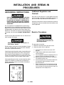
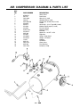
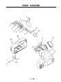
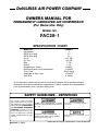
DeVILBISS AIR POWER COMPANY OWNERS MANUAL FOR PERMANENTLY LUBRICATED AIR COMPRESSOR (For Home Use Only) MODEL NO. FAC28-1 SPECIFICATION CHART Model No. Horsepower SCFM @ 40 psig SCFM @ 90 psig Cut-In Cut-Out Bore Stroke Voltage/Hertz/ Phase Minimum Branch Circuit Requirement *Fuse Type Amperage at Max. Load Tank Size FAC28-1 2 3.7 2.6 100 PSI 125 PSI 1 7/8" 1 1/4" 120/60/1 15 AMPS Quick Acting 10 AMPS 8 Gallon *A circuit breaker is preferred. Use only a fuse or circuit breaker that is the same rating as the branch circuit the air compressor is operated on. If the air compressor is connected to a circuit protected by fuses, use quick acting fuses. SAFETY GUIDELINES - DEFINITIONS This manual contains information that is important for you to know and understand. This information relates to protecting YOUR SAFETY and PREVENTING EQUIPMENT PROBLEMS. To help you recognize this information, we use symbols to the right. Please read the manual and pay attention to these sections. URGENT SAFETY INFORMATION - A HAZARD THAT WILL CAUSE SERIOUS INJURY OR LOSS OF LIFE. Information for preventing damage to equipment. IMPORTANT SAFETY INFORMATION - A HAZARD THAT MIGHT CAUSE SERIOUS INJURY OR LOSS OF LIFE. Information that you should pay special attention to. DeVilbiss Air Power Company • 213 Industrial Dr. • Jackson, TN 38301-9615 MGP-FAC28-1 4/6/98 TABLE OF CONTENTS Page ON-RECEIPT INSPECTION.................. 2 WARRANTY .......................................... 3 SAFETY GUIDELINES 4 Page Extension Cords ............................... 7 Voltage and Circuit Protection ......... 7 Grounding Instructions ..................... 8 Additional Regulators and Controls ............................................ 8 Break-In Procedures ......................... 8 WARNING CHART ............................. 4-5 OPERATING PROCEDURES ................ 9 GLOSSARY ............................................ 6 TROUBLESHOOTING GUIDE ......... 10-11 DUTY CYCLE ........................................ 6 STORAGE .............................................. 6 DESCRIPTION OF OPERATION ........... 7 Location of Air Compressor ................... 7 COMPRESSOR DIAGRAM AND PARTS LIST ........................................ 12 PUMP DIAGRAM ................................ 13 PUMP PARTS LIST ............................. 14 INSTALLATION AND BREAK-IN PROCEDURES ................................... 7-8 Location of Air Compressor ............ 7 2 — ENG SERVICE NOTES ................................. 15 LIMITED WARRANTY ONE YEAR FROM DATE OF PURCHASE All merchandise manufactured by DeVilbiss Air Power Company is warranted to be free of defects in workmanship and material which occur during the first year from the date of purchase by the original purchaser (initial user). Products covered under this warranty include: air compressors, *air tools, accessories, service parts, pressure washers, and generators used in consumer applications (i.e., personal residential household usage only). Air compressors, *air tools, accessories, service parts, pressure washers, and generators used in commercial applications (income producing) are covered by a 90 day warranty. DeVilbiss Air Power will repair or replace, at DeVilbiss's option, products or components which have failed within the warranty period. Repair or replacement, and service calls on 60 and 80 gallon air compressors, will be handled by Authorized Warranty Service Centers and will be scheduled and serviced according to the normal work flow and business hours at the service center location, and depending on the availability of replacement parts. All decisions of DeVilbiss Air Power Company with regard to this policy shall be final. This warranty gives you specific legal rights, and you may also have other rights which vary from state to state. RESPONSIBILITY OF ORIGINAL PURCHASER (Initial User): ❏ Retain original cash register sales receipt as proof of purchase for warranty work. ❏ Use reasonable care in the operation and maintenance of the product as described in the Owners Manual(s). ❏ Deliver or ship the product to the nearest DeVilbiss Air Power Authorized Warranty Service Center. Freight costs, if any, must be paid by the purchaser. ❏ Air compressors with 60 and 80 gallon tanks only will be inspected at the site of installation. Contact the nearest Authorized Warranty Service Center, that provides on-site service calls, for service call arrangement. ❏ If the purchaser does not receive satisfactory results from the Authorized Warranty Service Center, the purchaser should contact DeVilbiss Air Power Company. THIS WARRANTY DOES NOT COVER: ❏ Merchandise sold as reconditioned, floor models and/or display models. Any damaged or incomplete equipment sold "as is". ❏ Merchandise used as "rental" equipment. ❏ Merchandise that has become inoperative because of ordinary wear, misuse, freeze damage, use of ❏ ❏ ❏ ❏ ❏ ❏ improper chemicals, negligence, accident, improper and/or unauthorized repair or alterations including failure to operate the product in accordance with the instructions provided in the Owners Manual (s) supplied with the product. *Air Tools: O-Rings and driver blades are considered ordinary wear parts, therefore, they are warranted for a period of 45 days from the date of purchase. An air compressor that pumps air more than 50% during a one hour period is considered misuse because the air compressor is undersized for the required air demand. Maximum compressor pumping time per hour is 30 minutes. Merchandise sold by DeVilbiss Air Power which has been manufactured by and identified as the product of another company. The product manufacturer's warranty will apply. Repair and transportation costs of merchandise determined not to be defective. Cost associated with assembly, required oil, adjustments or other installation and start-up cost. ANY INCIDENTAL, INDIRECT OR CONSEQUENTIAL LOSS, DAMAGE, OR EXPENSE THAT MAY RESULT FROM ANY DEFECT, FAILURE OR MALFUNCTION OF THE PRODUCT. Some states do not allow the exclusion or limitation of incidental or consequential damages, so the above limitation or exclusion may not apply to you. IMPLIED WARRANTIES, INCLUDING THOSE OF MERCHANTABILITY AND FITNESS FOR A PARTICULAR PURPOSE, ARE LIMITED TO ONE YEAR FROM THE DATE OF ORIGINAL PURCHASE. Some states do not allow limitations on how long an implied warranty lasts, so the above limitations may not apply to you. DeVilbiss Air Power Company 213 Industrial Drive • Jackson, TN 38301-9615 • Telephone: 1-800-888-2468 , Ext. 2 • FAX: 1-800-888-9036 Form: SP-100-E - 4/25/96 3 — ENG IMPORTANT SAFETY INSTRUCTIONS • SAVE THESE INSTRUCTIONS • IMPROPER OPERATION OR MAINTENANCE OF THIS PRODUCT COULD RESULT IN SERIOUS INJURY AND PROPERTY DAMAGE. READ AND UNDERSTAND ALL WARNINGS AND OPERATING INSTRUCTIONS BEFORE USING THIS EQUIPMENT. HAZARD RISK OF BURSTING WHAT CAN HAPPEN HOW TO PREVENT IT AIR TANK THE FOLLOWING CONDITIONS COULD LEAD TO A WEAKENING OF THE TANK, AND RESULT IN A VIOLENT TANK EXPLOSION: 1. FAILURE TO PROPERLY DRAIN CONDENSED WATER FROM THE TANK, CAUSING RUST AND THINNING OF THE STEEL TANK. DRAIN TANK DAILY OR AFTER EACH USE. IF TANK DEVELOPS A LEAK, REPLACE IT IMMEDIATELY WITH A NEW TANK OR NEW COMPRESSOR OUTFIT. 2. MODIFICATIONS OR ATTEMPTED REPAIRS TO THE TANK. NEVER DRILL INTO, WELD, OR MAKE ANY MODIFICATIONS TO THE TANK OR ITS ATTACHMENTS. 3. UNAUTHORIZED MODIFICATIONS TO THE PRESSURE SWITCH, SAFETY VALVE, OR ANY OTHER COMPONENTS WHICH CONTROL TANK PRESSURE. THE TANK IS DESIGNED TO WITHSTAND SPECIFIC OPERATING PRESSURES. NEVER MAKE ADJUSTMENTS OR PARTS SUBSTITUTIONS TO ALTER THE FACTORY SET OPERATING PRESSURES. ATTACHMENTS RISK OF EXPLOSION OR FIRE & ACCESSORIES EXCEEDING THE PRESSURE RATING OF AIR TOOLS, SPRAY GUNS, AIR OPERATED ACCESSORIES, TIRES AND OTHER INFLATABLES CAN CAUSE THEM TO EXPLODE OR FLY APART, AND COULD RESULT IN SERIOUS INJURY. FOLLOW THE EQUIPMENT MANUFACTURERS RECOMMENDATION AND NEVER EXCEED THE MAXIMUM ALLOWABLE PRESSURE RATING OF ATTACHMENTS. NEVER USE COMPRESSOR TO INFLATE SMALL LOW-PRESSURE OBJECTS SUCH AS CHILDREN’S TOYS, FOOTBALLS, BASKETBALLS. ETC. IT IS NORMAL FOR ELECTRICAL CONTACTS WITHIN THE MOTOR AND PRESSURE SWITCH TO SPARK. ALWAYS OPERATE THE COMPRESSOR IN A WELL VENTILATED AREA FREE OF COMBUSTIBLE MATERIALS, GASOLINE OR SOLVENT VAPORS. IF ELECTRICAL SPARKS FROM COMPRESSOR COME INTO CONTACT WITH FLAMMABLE VAPORS, THEY MAY IGNITE, CAUSING FIRE OR EXPLOSION. IF SPRAYING FLAMMABLE MATERIALS, LOCATE COMPRESSOR AT LEAST 20 FEET AWAY FROM SPRAY AREA. AN ADDITIONAL LENGTH OF HOSE MAY BE REQUIRED. STORE FLAMMABLE MATERIALS IN A SECURE LOCATION AWAY FROM COMPRESSOR. RISK OF ELECTRICAL SHOCK RESTRICTING ANY OF THE COMPRESSOR VENTILATION OPENINGS WILL CAUSE SERIOUS OVERHEATING AND COULD CAUSE FIRE. NEVER PLACE OBJECTS AGAINST OR ON TOP OF COMPRESSOR. OPERATE COMPRESSOR IN AN OPEN AREA AT LEAST 12 INCHES AWAY FROM ANY WALL OR OBSTRUCTION THAT WOULD RESTRICT THE FLOW OF FRESH AIR TO THE VENTILATION OPENINGS. YOUR AIR COMPRESSOR IS POWERED BY ELECTRICITY. LIKE ANY OTHER ELECTRICALLY POWERED DEVICE, IF IT IS NOT USED PROPERLY IT MAY CAUSE ELECTRIC SHOCK. NEVER OPERATE THE COMPRESSOR OUTDOORS WHEN IT IS RAINING OR IN WET CONDITIONS. NEVER OPERATE COMPRESSOR WITH COVER COMPONENTS REMOVED OR DAMAGED. CONTINUE NEXT PAGE 4 — ENG * HAZARD RISK OF ELECTRICAL SHOCK RISK FROM FLYING OBJECTS RISK TO BREATHING RISK FROM MOVING PARTS RISK OF BURNS WHAT CAN HAPPEN HOW TO PREVENT IT REPAIRS ATTEMPTED BY UNQUALIFIED PERSONNEL CAN RESULT IN SERIOUS INJURY OR DEATH BY ELECTROCUTION. ANY ELECTRICAL WIRING OR REPAIRS REQUIRE ON THIS PRODUCT SHOULD BE PERFORMED BY AUTHORIZED SERVICE CENTER PERSONNEL IN ACCORDANCE WITH NATIONAL AND LOCAL ELECTRICAL CODES. ELECTRICAL GROUNDING: FAILURE TO PROVIDE ADEQUATE GROUNDING TO THIS PRODUCT COULD RESULT IN SERIOUS INJURY OR DEATH FROM ELECTROCUTION. SEE GROUNDING INSTRUCTIONS. MAKE CERTAIN THAT THE ELECTRICAL CIRCUIT TO WHICH THE COMPRESSOR IS CONNECTED PROVIDES PROPER ELECTRICAL GROUNDING, CORRECT VOLTAGE AND ADEQUATE FUSE PROTECTION. THE COMPRESSED AIR STREAM CAN CAUSE SOFT TISSUE DAMAGE TO EXPOSED SKIN AND CAN PROPEL DIRT, CHIPS, LOOSE PARTICLES AND SMALL OBJECTS AT HIGH SPEED, RESULTING IN PROPERTY DAMAGE OR PERSONAL INJURY. ALWAYS WEAR ANSI Z87.1 APPROVED SAFETY GLASSES WITH SIDE SHIELDS WHEN USING THE COMPRESSOR. THE COMPRESSED AIR FROM YOUR COMPRESSOR IS NOT SAFE FOR BREATHING! THE AIR STREAM MAY CONTAIN CARBON MONOXIDE, TOXIC VAPORS OR SOLID PARTICLES. NEVER INHALE AIR FROM THE COMPRESSOR EITHER DIRECTLY OR FROM A BREATHING DEVICE CONNECTED TO THE COMPRESSOR. SPRAYED MATERIALS SUCH AS PAINT, PAINT SOLVENTS, PAINT REMOVER, INSECTICIDES, WEED KILLERS, ETC.. CONTAIN HARMFUL VAPORS AND POISONS. WORK IN AN AREA WITH GOOD CROSSVENTILATION. READ AND FOLLOW THE SAFETY INSTRUCTIONS PROVIDED ON THE LABEL OR SAFETY DATA SHEETS FOR THE MATERIAL YOU ARE SPRAYING. USE A NIOSH/MSHA APPROVED RESPIRATOR DESIGNED FOR USE WITH YOUR SPECIFIC APPLICATION. MOVING PARTS CAN CAUSE SERIOUS INJURY OR DAMAGE IF THEY COME INTO CONTACT WITH YOU OR YOUR CLOTHING. DO NOT REMOVE THE PROTECTIVE COVERS FROM THIS PRODUCT. NEVER OPERATE THE COMPRESSOR WITH GUARDS OR COVERS WHICH ARE DAMAGED OR REMOVED. ATTEMPTING TO OPERATE OR REPAIR COMPRESSOR WITH PROTECTIVE SHROUDS REMOVED CAN EXPOSE YOU TO MOVING PARTS AND ELECTRICAL SHOCK. ANY REPAIRS REQUIRED ON THIS PRODUCT SHOULD BE PERFORMED BY AUTHORIZED SERVICE CENTER PERSONNEL. A PORTABLE COMPRESSOR CAN FALL FROM A TABLE, WORKBENCH OR ROOF CAUSING DAMAGE TO THE COMPRESSOR WHICH COULD EXPOSE YOU TO HAZARDOUS MOVING OR ELECTRICAL PARTS. ALWAYS OPERATE COMPRESSOR IN A STABLE SECURE POSITION TO PREVENT ACCIDENTAL MOVEMENT OF THE UNIT. NEVER OPERATE COMPRESSOR ON A ROOF OR OTHER ELEVATED POSITION. USE ADDITIONAL AIR HOSE TO REACH HIGH LOCATIONS. THE COMPRESSOR CYCLES AUTOMATICALLY WHEN THE PRESSURE SWITCH IS IN THE ON/AUTO POSITION. ALWAYS TURN OFF THE COMPRESSOR, BLEED PRESSURE FROM THE AIR HOSE AND TANK UNPLUG FROM ELECTRICAL OUTLET BEFORE PERFORMING MAINTENANCE OR ATTACHING TOOLS AND ACCESSORIES. TOUCHING EXPOSED METAL SUCH AS THE COMPRESSOR HEAD OR OUTLET TUBE CAN RESULT IN SERIOUS BURNS. NEVER TOUCH ANY EXPOSED METAL PARTS ON COMPRESSOR DURING OR IMMEDIATELY AFTER OPERATION. COMPRESSOR WILL REMAIN HOT FOR SEVERAL MINUTES AFTER OPERATION. NEVER POINT ANY NOZZLE OR SPRAYER TOWARD ANY PART OF THE BODY OR AT OTHER PEOPLE OR ANIMALS. CTMCWPS — 5/1/97 5 — ENG GLOSSARY SCFM or CFM: Standard Cubic Feet per Minute; a unit of measurement of air delivery. PSIG or PSI: Pounds per square inch gauge. CUT-OUT PRESSURE: When you turn on your air compressor and it begins to run, air pressure in the air tank begins to build. It builds to approximately 125 PSI before the motor automatically shuts off .The high pressure at which the motor shuts off is called "cut-out pressure." CUT-IN PRESSURE: While the motor is off, air tank pressure drops as you continue to use your accessory. When the tank pressure drops to approximately 100 PSI the motor will restart automatically. The low pressure at which the motor automatically re-starts is called "cut-in pressure." DUTY CYCLE All DeVilbiss Air Power manufactured air compressors should be operated on not more than a 50% duty cycle. This means an air compressor that pumps air more than 50% of one hour is considered misuse, because the air compressor is undersized for the required air demand. Maximum compressor pumping time per hour is 30 minutes. STORAGE When you have finished using the air compressor: 1. Set the "ON/OFF" switch to "OFF" and unplug the cord. 3. Protect the electrical cord and air hose from damage by winding them loosely around the air compressor. 2. Review the "Operating Procedures" section (page 9). Be sure to drain the water from the air tank. 4. Store the air compressor in a clean and dry location. 6 — ENG DESCRIPTION OF OPERATION Air Compressor Pump: To compress air, the piston moves up and down in the cylinder. On the downstroke, air is drawn in through the intake valves. The exhaust valves remain closed. On the upstroke of the piston, air is compressed. The intake valves close and compressed air is forced out through the exhaust valves, through the outlet tube, through the check valve and into the air tank. Working air is not available until the compressor has raised the tank pressure above that required at the air outlet. Check Valve: When the air compressor is operating, the check valve is “open”, allowing compressed air to enter the air tank. When the air compressor reaches “cut-out” pressure, the check valve “closes”, allowing air pressure to remain inside the air tank. Pressure Switch: The pressure switch automatically starts the motor when the tank pressure drops below the factory set “cut-in” pressure. It stops the motor when the air tank pressure reaches the factory set “cut-out” pressure. Regulator: The air pressure coming from the air tank is controlled by the regulator. Turn the regulator knob clockwise to increase pressure and counterclockwise to decrease pressure. To avoid minor readjustment after making a change in pressure setting, always approach the desired pressure from a lower pressure. When reducing from a higher to a lower setting, first reduce to pressure less. than that desired, then bring it up to the desired pressure. Depending on the air requirements of each particular accessory, the outlet regulated air pressure may have to be adjusted while operating the accessory. Outlet Pressure Gauge: The outlet pressure gauge indicates the air pressure available at the outlet side of the regulator. This pressure is controlled by the regulator and is always less or equal to the tank pressure. See “Operating Procedures”. Tank Pressure Gauge: The tank pressure gauge indicates the reserve air pressure in the tank. Cooling System: This compressor contains an advanced design cooling system. At the heart of this cooling system is an engineered fan. It is perfectly normal for this fan to blow air through the vent holes in large amounts. You know that the cooling system is working when air is being expelled. Air Intake Filter: This unit requires no air filter due to the unique design of the air intake system. Drain Valve: The drain valve is located at the base of the air tank and is used to drain condensation at the end of each use. INSTALLATION AND BREAK-IN PROCEDURES Location of the Air Compressor Extension Cords Operate the air compressor in a dry, clean, cool and well ventilated area. The air compressor pump and case are designed to allow for proper cooling. Clean or blow off dust or dirt that collects on the air compressor. A clean air compressor runs cooler and provides longer service. The ventilation openings on your air compressor are necessary to maintain proper operating temperature. Do not place rags or other containers on or near these openings. Use extra air hose instead of an extension cord to avoid voltage drop and power loss to the motor. Voltage and Circuit Protection See front cover. If an extension cord must be used, be sure it is: • a 3-wire extension cord that has a 3-blade grounding plug, and a 3-slot receptacle that will accept the plug on the compressor. • in good condition. • no longer than 50 feet. • 14 gauge (AWG) or larger. (Wire size increases as gauge number decreases.) 12 AWG, 10 AWG and 8 AWG may also be used. DO NOT USE 16 OR 18 AWG. 7 — ENG INSTALLATION AND BREAK-IN PROCEDURES GROUNDING INSTRUCTIONS RISK OF ELECTRICAL SHOCK! IN THE EVENT OF A SHORT CIRCUIT, GROUNDING REDUCES THE RISK OF SHOCK BY PROVIDING AN ESCAPE WIRE FOR THE ELECTRIC CURRENT. THIS AIR COMPRESSOR MUST BE PROPERLY GROUNDED. The air compressor is equipped with a cord having a grounded wire with an appropriate grounding plug. The plug must be used with an outlet that has been installed and grounded in accordance with all local codes and ordinances. The outlet must have the same configuration as the plug. See illustration. DO NOT USE AN ADAPTER. Additional Regulators and Controls Since the air tank pressure is usually greater than that which is needed, a regulator is employed to control the air pressure ahead of any individual air driven device. Separate air transformers which combine the function of air regulation, moisture and dirt removal should be used where applicable. Break-in Procedures Inspect the plug and cord before each use. Do not use if there are signs of damage. Serious damage may result if the following break-in instructions are not closely followed. IMPROPER GROUNDING CAN RESULT IN ELECTRICAL SHOCK. Do not modify the plug that has been provided. If it does not fit the available outlet, the correct outlet should be installed by a qualified electrician. This procedure is required: 1. Before the air compressor is put into service. 2. When the check valve is replaced. If repairing or replacing cord or plug, the grounding wire must be kept separate from the current-carrying wires. Never connect the grounding wire to a flat blade plug terminal. The grounding wire has insulation with an outer surface that is green - with or without yellow stripes. If these grounding instructions are not completely understood, or if in doubt as to whether the compressor is properly grounded, have the installation checked by a qualified electrician. 8 — ENG a. Set the pressure switch lever to the "OFF" position. b. Plug the power cord into the correct branch circuit receptacle. c. Turn the regulator clockwise, opening it fully, to prevent air pressure build-up in the tank. d. Move the pressure switch lever to "ON/AUTO". The compressor will start. e. Run the compressor for 15 minutes. Make sure the regulator is open and there is no tank pressure build-up. f. After 15 minutes, close the regulator by turning knob counterclockwise. The air receiver will fill to cut-out pressure and the motor will stop. The compressor is now ready for use. OPERATING PROCEDURES 1. Before attaching air hose or accessories, make sure the OFF/AUTO lever is set to “OFF” and the air regulator or shut-off valve is closed. When you are finished: 6. Set the “OFF/AUTO” lever to “OFF”. 7. Turn the regulator counterclockwise and set the outlet pressure to zero. 2. Attach hose and accessories. 8. Remove the air tool or accessory. 9. Open the regulator and allow the air to slowly bleed from the tank. Close the regulator when tank pressure is approximately 20 psi. TOO MUCH AIR PRESSURE CAUSES A HAZARDOUS RISK OF BURSTING. CHECK THE MANUFACTURER'S MAXIMUM PRESSURE RATING FOR AIR TOOLS AND ACCESSORIES. THE REGULATOR OUTLET PRESSURE MUST NEVER EXCEED THE MAXIMUM PRESSURE RATING. 10. Drain water from air tank. WATER WILL CONDENSE IN THE AIR TANK. IF NOT DRAINED, WATER WILL CORRODE AND WEAKEN THE AIR TANK CAUSING A RISK OF AIR TANK RUPTURE. 3. Turn the OFF/AUTO lever to “AUTO” and allow tank pressure to build. Motor will stop when tank pressure reaches “cut-out” pressure. 4. Open the regulator by turning it clockwise. Adjust the regulator to the correct pressure setting. Your compressor is ready for use. 5. Always operate the air compressor in well-ventilated areas; free of gasoline or other solvent vapors. Do not operate the compressor near the spray area. NOTE If drain cock valve is plugged, release all air pressure. The valve can then be removed, cleaned, then reinstalled. 11. After the water has been drained, close the drain cock or drain valve. The air compressor can now be stored. 9 — ENG TROUBLESHOOTING GUIDE PERFORMING REPAIRS MAY EXPOSE VOLTAGE SOURCES, MOVING PARTS OR COMPRESSED AIR SOURCES. PERSONAL INJURY MAY OCCUR. PRIOR TO ATTEMPTING ANY REPAIRS, UNPLUG THE COMPRESSOR AND BLEED OFF TANK AIR PRESSURE. PROBLEM CAUSE CORRECTION Excessive tank pressure safety valve pops off. Pressure switch does not shut off motor when compressor reaches “cutout” pressure. Move the pressure switch lever to the “OFF” position. If the outfit doesn’t shut off, unplug. If the electrical contacts are welded together, replace the pressure switch. Pressure '"cut-out" too high. Return the outfit to an authorized dealer to check and adjust, or replace switch. Air leaks at fittings. Tube fittings are not tight enough. Tighten fittings where air can be heard escaping. Check fittings with soapy water solution. DO NOT OVER-TIGHTEN. Air leaks in air tank or at air tank welds. Defective air tank. Air tank must be replaced. Do not repair the leak. DO NOT DRILL INTO, WELD OR OTHERWISE MODIFY AIR TANK OR IT WILL WEAKEN. THE TANK CAN RUPTURE OR EXPLODE. Pressure reading on the regulated pressure gauge drops when an accessory is used. It is normal for “some” pressure drop to occur. If there is an excessive amount of pressure drop when the accessory is used, adjust the regulator following the instructions on page 7. NOTE Adjust the regulated pressure under flow conditions (while accessory is being used). Air leak from safety valve. Possible defect in safety valve. Operate safety valve manually by pulling on ring. If valve still leaks, it should be replaced. Knocking Noise Defective check valve. Remove and clean, or replace. Compressor is not supplying enough air to operate accessories. Prolonged excessive use of air. Decrease amount of air usage. Compressor is not large enough for air requirement. Check the accessory air requirement. If it is higher than the SCFM or pressure supplied by your air compressor, you need a larger compressor. Hole in hose. Check and replace. 10 — ENG TROUBLESHOOTING GUIDE (Continued) PROBLEM CAUSE CORRECTION Compressor is not supplying enough air to operate accessories. (cont'd) Check valve restricted. Remove and clean, or replace. Air leaks. Tighten fittings. (See Air Leaks Section of Troubleshooting Guide.) Motor will not run. Tank pressure exceeds pressure switch “cut-in” pressure. Motor will start automatically when tank pressure drops below “cut-in” pressure of pressure switch. Wrong gauge wire or length of extension cord. Check for proper gauge wire and cord length. Check valve stuck open. Remove and clean, or replace. Loose electrical connections. Check wiring connection inside pressure switch and terminal box area. Paint spray on internal motor parts. Have checked at an Authorized Warranty Service Center. Do not operate the compressor in the paint spray area. See flammable vapor warning. Possible defective motor. Have checked at an Authorized Warranty Service Center. Fuse blown, circuit breaker tripped. 1. 2. 3. 4. Regulator knob has continuous air leak. Regulator will not shut off at air outlet. Damaged regulator. Check fuse box for blown fuse and replace, if necessary. Reset circuit breaker. Do not use a fuse or circuit breaker with higher rating than that specified for your particular branch circuit. Check for proper fuse. Check for low voltage conditions and/or proper extension cord. Disconnect the other electrical appliances from circuit or operate the compressor in its own branch circuit. Replace regulator. 11 — ENG AIR COMPRESSOR DIAGRAM & PARTS LIST KEY NO. PART NUMBER DESCRIPTION 1 2 3 4 5 6 7 8 9 10 11 12 13 14 15 16 17 18 19 20 97503734 SS-2707 CAC-4299 CAC-60 SSF-8080-ZN AC-0345 SSF-612 AC-0364 AC-0353 SUDL-413-2 AC-0027-2 SSP-480 AC-0007 AC-0009-1 AC-0010-1 H-2101 SSP-473 CAC-1275 SSP-490 CAC-1254 Safety Valve Drain Valve Wheel 6" (2 used) Shoulder Bolt (2 used) Nut Hex 3/8-16 UNC-2B (2 used) Handle Screw #10 - 16 x 1 Type AB (2 used) Molded Foot Bumper (2 used) Pressure Switch Cord Assembly Manifold Nipple 1/4 - 18 NPT x 2.50 Regulator Gauge - Right Hand Gauge - Left Hand Adaptor Nut Sleeve Check Valve Face Bushing Isolator (4 used) 12 — ENG PUMP DIAGRAM 13 — ENG PARTS LIST KEY NO. x * * * x * x x 1 2 3 4 5 6 7 8 9 10 11 12 13 14 15 16 17 18 PART NUMBER DESCRIPTION ----CAC-1196 CAC-1212 CAC-1199 CAC-4323 SSG-8169 DAC-269 ------------Z-CAC-4130-1 CAC-1342 CAC-1213 AC-0470 AC-0471 --------AC-0354 Screw #10-24 x 7/8 LG. hex head thd forming (4 used) Cylinder head Tube seal Head gasket Valve plate assembly "O" ring Outlet Tube Rod assembly Screw 3/8-16 x 1.25 LG. hex socket flat head Cylinder sleeve Motor/Endbell assembly Timing belt Pump isolator Shroud (right) Shroud (left) Screw #10-9 x 1/2 LG. Phillips head thd forming (4 used) Screw, ground #8-32 x 3/8 LG. Slotted hex head, thd forming Motor Cord Assembly * KK-4930 Isolator Kit includes items 3, 4, 6, 13. x KK-4929 Fastener Kit includes items 1, 9, 16, 17. • KK-4964 Connecting Rod Kit includes items 8, 10. 14 — ENG SERVICE NOTES 15 — ENG DeVILBISS AIR POWER COMPANY OWNERS MANUAL FOR PERMANENTLY LUBRICATED AIR COMPRESSOR (For Home Use Only) MODEL NO. FAC28-1 Call our Toll Free Number 1-800-888-2468, Ext 2, then 1, to obtain the location of the nearest Authorized Service Center for ordering repair parts and for warranty repairs. When ordering repair parts from your local Authorized Service Center, always give the following information: •Model number of your product •Part number and description of the item you wish to purchase Attach Sales Receipt Here. Retain Original Sales Receipt as Proof of Purchase for Warranty Repair Work. DeVilbiss Air Power Company • 213 Industrial Drive • Jackson, TN 38301-9615