1
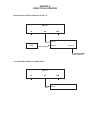
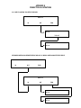
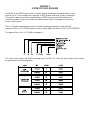
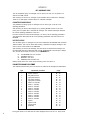
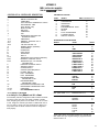
X-15 USER MANUAL TABLE OF CONTENTS
INTRODUCTION
CONNECTIONS
Power Input
MIDI OUT
MIDI IN
MIDI THRU
BYPASS/DC Footswitch
TELL-TALES/CONTROLS
Numeric Display
Power Up
LED lndicators
Activator Pads
Expression Pedals
OPERATION
MODES
PRESET MODE
EFFECT MODE
BYPASS MDDE
SETUP MODE
SAVING EDlTED PARAMETERS
MISCELLANEOUS
APPENDIX A
Programmlng Examples
Edit Controlled Device's MIDI Program Table (MPT)
wlth the X-15
Setup an ART Multiverb, DR-X, or SGE for
MIDI Control of the Pitch Parameter of
the Pitch Transposer
Using the X-15 to Turn On or Off Effects in
a Preset Uslng Effect Mode and Activator
APPENDIX B
Connectlon Illustrations
APPENDIX C
System Exclusive Messages
Unit Handshake Group
Parameter Exchange Group
Unit Status Group
Parameter Exchange Data Format
APPENDIX D
MIDI: Controllers & Numbers
SCALING: Suggestion Settings
TROUBLESHOOTING
WARRANTY & SERVICE INFORMATION
1
2
2
2
2
2
2
2
2
2
2
2
2
3
3
3
4
4
4
7
7
7
8
8
8
9, 10
11
12
12
12
12
13
13
14
14
INTRODUCTION
Congratulations and thank you for purchasing the new ART X-15 ULTRAFOOT
Digital Real Time Effects Control System.
The ART X-15 ULTRAFOOT puts the power of real time control at your feet in
a format that is super-easy to use. The power of the X-l5 is awesome. The
ART X-15 ULTRAFOT is a real time MIDI foot controller capable of sending
MIDI Program Message Changes to any MIDI controlled device, AND, control
MIDI assignable parameters via the TWO real time expression pedals on board,
AND, access individual effects of ART SGX and ALPHA effects processors.
FEATURES:
- Instant access of individual effects
-
TWO real time assignable expression pedals
Simple, “plug in and go” operation
DC bypass out jack for use with older units
Rugged steel assembly
MIDI IN, OUT, &, THRU
Send MIDI data on three separate channels at once
Durable composite activator pads
Mode select allows multifunction use
Non-Volatile memory, stores and remembers your
changes
Bright visible program display
Switchable LED indicator lights
Extra heavy-duty scuff resistant paint
Dump parameters to MIDI storage device
The X-15 ULTRAFOOT is a simple device to use extending the flexibility of any
MIDI controlled device. For instructions on how to implement and use the X-15 in
your system, please read and refer to the rest of this manual.
CONNECTIONS
Only two connections made to the rear of the X-15 are needed
for operation. The only accessories you will need to use
your X-15 ULTRAFOOT is a power source and MIDI cable(s).
Power Input
Plug the power adapter into a proper power outlet then connect to the X-15.
MIDI OUT
The MIDI output jack is used to transmit all MIDI control information from the X-15 to whichever MIDI device you wish
to control. Connect the MIDI cable to the 5 pin MIDI OUT
jack on the X-15 and then to the MIDI IN jack of the device
you are going to control.
MIDI IN
This jack receives the MIDI signal containing the MIDI
messages. It enables you to “talk” to the X-15 from an
external source such as a computer equipped with MIDI
ports and associated software or a sequencer. Actually, you
may use any MIDI device to send messages to the X-15.
Any MIDI information sent to the MIDI In jack is echoed to
the MIDI Thru jack.
MIDI THRU
A MIDI Thru jack is provided on the X-15 allowing you to
continue a chain of MIDI devices and let MIDI information
pass “thru” the unit to the next one. Information leaving the
Thru jack is a direct copy of the MIDI messages received at
the MIDI In jack. The information is buffered so the integrity
of the signal is not degraded when passing thru.
All MIDI Jacks are standard 5 pin DIN connectors utilizing standard MIDI connections. No phantom power is
present on the unused terminals. ART recommends
these unused terminals remain unused.
See Appendix B for MIDI hook-up illustrations.
TELL-TALES/CONTROLS
NUMERIC DISPLAY
The Seven Segment Numeric Display keeps you constantly
informed of your Preset Number, Expression Pedal values,
MIDI Channel, Programming Characters, and Error Messages.
AlI information is displayed using decimal based numbers in
most cases.
Power up
When power is first applied to the X-15, it runs through an
autotest sequence turning on everything that lights up for
about a second, then it displays “Art” indicating everything
is fine. This allows the user to be sure that all display
elements are working and that displayed information will be
accurate.
During power-up the X-15 performs a checksum of the ROM
contents, if there is an error, an error message will appear in
the display. If the ROM checksum is incorrect, “E-C” will
display for ten seconds, press any pad to operate normally.
In the event power is interrupted for a brief period of time
and the X-15 does not reset itself properly, just unplug and
plug back in the power plug at the power in jack.
LED Indicators
LEDs located in the upper left hand corner of the activator
pads 1 through 10 indicate which pad is active. The MODE
and BYPASS activator pads have their indicator LEDs
located towards their upper right corner. These LEDs are
also used to indicate the different programming modes you
may be in.
ActivatorPads
Pads on the pedal are labeled from left to right: Select
Arrow UP and Arrow DOWN, MODE, BYPASS, l/EXCITER,
2/COMPRESSOR, 3/DlSTORTlON, 4/EQUALlZER,
5/EXPANDER/NOlSE GATE, 6/REVERB, 7/DELAY, 8/PlTCH
TRANSPOSER, 9/FLANGE/CHORUS and 10/SPECIAL
EFFECTS. The black activator pads are what you use to
activate or program the X-15's many functions.
BYPASS/DC FOOTSWITCH
Expression Pedals
A standard 1/4" jack is the output port for a variety of footswitch configurations. This jack may be programmed to
operate in conjunction with the BYPASS pad as a momentary open or closed switch or an on/off switch. Some amp
channel switching or other switch applications could be
done using this jack. Use a standard two conductor guitar
cord to connect this jack to its intended termination. A
standard two conductor speaker cable may also be used
since no audio is being passed along the conductors.
Here are the two pedals that make the X-15 the ultimate
MIDI foot controller. The two expression pedals may be programmed individually to control any MIDI controllable parameter in ANY MIDI device. These pedals produce a control
voltage using an optical encoding device which is converted
into MIDI information. Try to avoid shining extremely bright
lights into the pedals. No harm will come to the device, but,
you. may affect the operation of the encoders by creating
unwanted information.
When the pedal is in the full up position, a minimum value
is present and as the pedal is gradually pushed down, the
value increases to its maximum value when all the way down.
OPERATION
banks of ten presets. A preset is selected (a MIDI program
change message is sent) when a numbered activator pad is
pressed.
The ART X-15 has four major Modes of operation. These
Modes are called PRESET, EFFECT SETUP, and BYPASS
Mode. Operation of the X-15 is defined and executed by
these Modes. To change between Preset and Effect Mode,
you need only to press the MODE activator pad. Each time
you press the pad the X-15 toggles between the two modes.
Access to Setup Mode is accomplished by pressing the
MODE pad and one additional activator pad as described in
the Setup section. Bypass Mode is actually one of the programmable sub-modes in Setup Mode. We have covered
Bypass Mode separately for your programming convenience.
When you enter preset mode, the X-15 checks to see if a
program change message has been sent since power-on. If
one has, the preset number is displayed and the associated
LED for that preset will light. If a program change message
hasn’t been sent yet, the current bank is displayed.
MODES
CHANGING BETWEEN MODES
Pressing and releasing the MODE button alone toggles
between preset and effect mode. Pressing the MODE button
along with the 1, 2, 3, 4, 5, or 6 buttons enters Setup Mode.
FIRST TIME USE
When you hook up your X-15 ULTRAFOOT for the first time,
we suggest you perform a Factory Reset to ensure all parameters and functions are at their initial values. This will alleviate
some minor aggravation on your part if the X-15 does not
operate as we describe them in the manual! To perform a
factory reset, press simultaneously the UP, 2, and 5 buttons
with the power on. You may find it much easier to perform
this function with your hands!
PRESET MODE
Example ofRecalling a Preset
As an example, if you want to select preset 77 while you
are in Preset Mode, press and hold the UP pad until 71
is displayed by the seven segment display, then press
pad 7. VIOLA!, preset 77 is active.
NOTE: In preset mode, whenever the display is showing a
preset, the numbered LED associated with that preset is lit.
Whenever the display is showing a bank, none of the
numbered LEDs are lit.
When power is applied to the X-15, it automatically comes up
in Preset Mode ready to recall a preset. Preset Mode allows
you to use the activator, UP, and DOWN pads to select MIDI
presets 1 thru 128 (MIDI program numbers 0 thru 127) in the
device you’re hooked up to. Presets are arranged in twelve
Each time the X-15 is powered up, it will default to bank one
with no preset active. At this point, you must select a preset
using the UP/DOWN buttons and an activator pad.
Program Message Change
Pressing any of the numbered pads does two things, (1) send
a program change message out the MIDI port, and (2) displays
the preset number. The program sent is the current bank
number (one through 121, in increments of ten) plus one, less
the value of the button pressed (preset = bank + button 1,
program = bank + button 1,-1) This means, preset 77 is
program 76.
The preset last selected remains active until another preset
button is pressed. You may change your bank anytime
without changing the current preset.
The current bank is changed with the UP and DOWN buttons. Pressing either one will increment or decrement
(respectively) the bank (in tens). Holding either button down
will increment or decrement four times a second, after an initial half-second pause. When the current bank is changed,
the new bank is displayed, unless a preset has been
selected, and that preset is in the current bank. When this
happens, the preset is displayed. UP and DOWN “wrap” at
the minimum and maximum values, pressing DOWN while
at the lowest bank yields the maximum bank, and
Vice-versa.
The X-15 has two impossible presets, these are numbers
129 and 130 which cannot be recalled. MIDI specifications
don’t allow either to exist. When the user attempts to select
these presets, the display shows the error message “E-P”
and the numbered LED last pressed (either nine or ten)
flashes. No MIDI message is sent. This error will stay until a
valid preset is sent, the bank is changed, or another mode
is selected (either effect or setup).
Returningto PresetMode From EffectMode
If you return to Preset Mode from Effect Mode, your last
preset recalled remains active. When you switch back to
Preset Mode, the preset number is displayed and the corresponding LED is lit automatically.
EFFECT MODE
SelectingaPreset
To select a preset in Effect Mode, use the UP/DOWN pads.
Each time either pad is pressed, you increment up or
down one preset. The preset is recalled automatically
and is displayed by the seven segment display only. No
pad LED indicator will light.
Upon entry to Effect Mode, a check is made to see if a program change message has been sent since power-on. if one
has, the X-15 shows the preset number and unlike in preset
mode, the associated LED is not lit.
Pressing a numbered button causes a controller change message to be sent out the MIDI port. The controller number is
defined either by the X-15’s initial values or by you from
editing Setup Mode.
The X-15 remembers the state (on or off) of each of the ten
controllers. Pressing a numbered button toggles the current
state, which in turn does two things, (1) send a controller
change message out the MIDI port, and (2) change the state
of the LED. The LEDs show the current state of each controller, lit is on and unlit is off.
Pressing the UP and DOWN buttons increments and decrements the current preset by one, and sends a program change
message out the MIDI port. UP and DOWN “wrap” at the
minimum and maximum values, pressing DOWN while at
the lowest bank yields the maximum bank, and vice-versa.
To edit the assigned controllers, use sub-mode 4 in
Setup Mode.
Bypass works as described under preset mode.
BYPASS MODE
The BYPASS button and LED operate identically in either
preset or effect mode. There are six possible settings for
bypass:
Value Jack
1
X
X
2
3
X
4
X
5
6
X
MIDI Momentary Toggle LED Polarity
X
normal
X
reverse
X
normal
X
reverse
X
X
remote
X
X
remote
In modes one through four, the bypass jack is used to communicate bypass mode to the outside world. In mode five,
the bypass jack is not used at all, bypass mode is sent as a
controller message out the MIDI port.
Within the six bypass modes, there are two principal submodes; momentary and toggle. In momentary mode, the
state of the bypass output changes for as long as the
BYPASS button is held down mimicking directly a momentary switch. Toggle mode allows for the state of the bypass
jack to change every time the BYPASS button is initially
pressed, just like an on/off switch.
in modes one and three, the state of the bypass LED is the
state of the bypass jack when the bypass jack is “on” (closed),
the bypass LED is lit. Modes two and four reverse this when
the bypass jack is “off” (open), the bypass LED is lit.
Mode five acts like mode three, except instead of the bypass jack, the MIDI port is used as the bypass output. The
4
bypass LED is turned on and off as in mode three, but
the bypass LED can also be remotely controlled via the
MIDI port. For detailed information see the section for
Set-up Mode 3.
Mode six sends a bypass message two different ways. Both
the MIDI Out port and the 1/4” jack are used to send a “Bypass”
message. The 1/4” jack acts like it would in mode 1 and the
MIDI port would act as it would in mode 5.
SETUP MODE
You may never need to use Setup Mode due to its complete
preprogramming. Read this section for all information necessary to change settings and how Setup Mode works.
As mentioned earlier, when the MODE button is pressed
together with the 1, 2, 3, 4, 5 or 6 buttons, Setup Mode is
entered. You may change between the six different setup
sub-modes at any time while you are in setup mode.
ExampleofEntering Setup Mode and Changing a Parameter
in this example we will enter Setup Mode and select submode 5 parameter 3, setting the BYPASS function for a
normal on/off switch. First, enter Setup Mode by pressing
and holding down the MODE pad and then pressing the
#5 pad. The display will show a flashing an “S” 1 and
the MODE LED will be flashing. To select parameter 3,
press the BYPASS pad [3] times. The display now shows
a flashing “b” 6. Press the UP button [3] times, the number now changes to 3. The BYPASS function is now programmed to operate like a normal on/off switch. When
the LED associated with the Bypass pad is lit, it indicates the switch is on. To exit Setup Mode press the
MODE pad. This will store your change into memory and
exit you to either Preset or Effect Mode, whatever mode
you were in previous to editing. Read this section for
detailed Setup Mode information.
Exampleof Changing to a Different Sub-Mode While in Setup Mode
If you wanted to assign the left expression controller but
mistakenly entered Setup Mode to assign the right expression controller, here’s what to do. First, what you
did was press and hold in the MODE and #1 pad, DON’T
press the #2 button, nothing will happen if you do. To
choose the correct sub-mode, press and hold the MODE
and #2 pad. To change between sub-modes you must
use the MODE button. For more information about Setup
Mode, keep reading this section.
In each of the sub-modes, pressing the UP and DOWN pads
increment and decrement the current value of the parameter
being edited. These “wrap” when the minimum and maximum values are reached. Pressing DOWN while at the
minimum value for a parameter yields the maximum value,
and vice-versa.
Sub-modes 1, 2, and 3 are indicated by the MODE LED flashing,
along with the 1, 2, or 3 LEDs flashing. Sub-mode 4 is indicated
by only pad indicator number 1 flashing. Sub-mode 5 is indicated by just the MODE LED and the first character in the
display flashing. Submode 6 is not indicated by anything.
Each sub mode parameter has a factory default setting. These
settings are present so the X-15 may be used immediately
out of the box to your setup. The defaults are selected for
average use. Of course, the parameters may be changed to
meet your requirements. This section covers the programming of your X-15.
The six sub-modes, what they do, how to change them and
default settings are as listed below.
FUNCTION
SUB MODE # ACCESS
1
MODE + 1
Set left pedal controller.
2
MODE + 2 Set right pedal controller.
3
MODE + 3 Set bypass controller.
4
MODE + 4 Set effect controller.
5
MODE + 5 Set miscellaneous parameters.
6
MODE + 6 Dump parameters
SUB-MODE 1: Setting the Left Pedal Controller
In sub-mode 1, you determine what controller the left pedal
becomes. See the list of MIDI controllers in Appendix D for
the number corresponding with the MIDI controller. To set
the pedal function, enter sub-mode 1 and select the proper
controller number using the UP/DOWN buttons. The seven
segment display shows the parameter value which is the
MIDI controller number.
DEFAULT VALUE = 4 (FOOT CONTROLLER)
SUB-MODE 2: Setting the Right Pedal Controller
In sub-mode 2, you determine what controller the right pedal
becomes. See the list of MIDI controllers in Appendix D for
the number corresponding with the MIDI controller. To set
the pedal function, enter sub-mode 2 and select the proper
controller number using the UP/DOWN buttons. The seven
segment display shows the parameter value which is the
MIDI controller number.
DEFAULT VALUE = 11 (EXPRESSION CONTROLLER)
SUB-MODE 3: Setting the Bypass Controller
Sub-Mode 3 allows you to program how the BYPASS switch
operates when set for MIDI operation. See the list of MIDI
controllers in Appendix D for the number corresponding with
the MIDI controller. Enter sub-mode 3 and select the proper
controller number using the UP/DOWN buttons. The seven
segment display shows the parameter value which is the
MIDI controller number.
DEFAULT VALUE = 84 (UNDEFINED)
EXAMPLES:
Setting theMIDI Bypass Function To Respond to Controller #7
Sub-mode three is an excellent way to induce extreme
value settings via MIDI. For example, you want to affect
the main volume of your keyboard remotely using your
foot. Using the X-15 you may do this. Enter sub-mode 3.
The MODE and #3 LED indicator will start to flash, and
the display will show 1. Use the UP (or DOWN) pad to
change the display to 7. Doing this sets the BYPASS button to send either a 0 or 7F (127) out the MIDI port when
the BYPASS switch is pressed, if it is programmed to
send a MIDI message. When the switch is pressed, the
main volume of the keyboard is toggled either to
minimum or maximum.
#5 pad. The display will show a flashing an “S” 1 and
the MODE LED will be flashing. To select parameter 5,
press the BYPASS pad [3] times. The display now shows
a flashing “b” 1(*). Press the UP button [4] tlmes, the
number now changes to 5. The BYPASS function is now
programmed to send MIDI commands.
(*)NOTE: If you programmed the BYPASS function in a previous
example the numbers in the display will flash “b” 3, and you
need only press the UP button [2] times.
SUB-MODE 4: Setting the Effects Controllers
Sub-Mode 4 allows you to assign the ten effect (number)
activator pads to turn on and off MIDI controllable effects.
The following chart shows the pad number, effect controlled
and assigned controller #‘s of the X-15’s initial settings.
PAD #
2
3
4
5
6
7
8
9
10
EFFECT
MIDI CONTROLLER #
EXCITER
70
COMPRESSOR
71
DISTORTION
72
EQUALIZER
73
EXPANDER/NOISE GATE
74
REVERB
75
DELAY
76
77
PITCH TRANSPOSER
FLANGE/CHORUS
78
SPECIAL EFFECTS
79
The above assigned effects controlled directly relate to
ART’s SGX product line but can be assigned to control any
MIDI devices effects if they are MIDI controllable.
The effects controllers only operate in EFFECT Mode. You
may edit the MIDI controller numbers while in Sub-mode 4.
DEFAULT VALUES = MIDI CONTROL NUMBERS SHOWN
IN ABOVE CHART
EXAMPLE:
Editing the Activator Pad MIDI Controller Number
In this example we will enter Setup Mode and select submode 4 and edit the controller number for pad number 1.
First, enter Setup Mode by pressing and holding down
the MODE pad and then pressing the #4 pad. The display
will show the number 70, and the #1 pad LED will be flashing.
To edit the value for pad #1, press the UP/DOWN pads until
the desired # appears. The display will show the MIDI
controller number. To exit Setup Mode press the MODE
pad. This will store your change into memory and exit
you to either Preset or Effect Mode, whatever mode you
were in previous to editing. Read this section for detailed
Setup Mode information.
ProgrammingtheBYPASS Function to Bend a
MIDI Bypass Command
In this example we will enter Setup Mode and select submode 5 parameter 5, setting the BYPASS function for
MIDI commands. Flrst, enter Setup Mode by pressing
and holding down the MODE pad and then pressing the
5
SUB-MODE 5
In sub-mode five, there are six parameters that can be edited.
Submode five flashes the first character of the display, and
uses the other two digits to show the value. To edit the parameter, enter sub-mode 5, press the BYPASS button to cycle
through the parameters, and use the UP and DOWN buttons
to select the appropriate value. This table shows the display,
parameter, description, and the available settings for the
parameter.
PARAMDISPLAY ETER
S
L
r
b
y
d
DESCRIPTION
RANGE
1
System MIDI channel
1-16
Left pedal MIDI channel
2
1-16
Right pedal MIDI channel
3
1-16
4
Bypass mode
1-6
5
Merger mode
0-1
6 Pedal inter-message delay 0-15
DEFAULT
VALUE
1
1
1
6
0
5
Parameter 1 Setting the System MIDI Channel
To set the MIDI channel for all your “system” data information both for sending and receiving, first, make sure
there is a capital “S” flashing in the display and then use
the UP/DOWN pads to select MIDI channel 1 through 16.
DEFAULT VALUE =1 (CHANNEL 1)
Parameter 2 Setting the Left Pedal MIDI Channel
To set the MIDI channel for sending information with the Left
expression pedal, first, make sure there is a capital “L” flashing
in the display and then use the UP/DOWN pads to select
MIDI channel 1 through 16. DEFAULT VALUE =1 (CHANNEL 1)
Parameter 3 Setting the Right Pedal MIDI Channel
To set the MIDI channel for sending information with the
Right expression pedal, first, make sure there is a lower
case “r” flashing in the display and then use the UP/
DOWN pads to select MIDI channel 1 through 16. DEFAULT
VALUE =1 (CHANNEL 1)
Parameter 4 Setting the Bypass Function
To set the function of the BYPASS pad, first make sure there
is a lower case “b” flashing in the display. Select a value
from 1 to 6 referring to the following chart and descriptions.
Value Jack MIDI
1
2
3
4
5
6
X
X
X
X
x
Momentary Toggle
X
X
X
x
X
X
X
X
LED Polarity
normal
reverse
normal
reverse
remote
remote
There are two principal types of switch functions you can
choose, momentary and toggle. In momentary mode, the
state of the bypass output changes for as long as the
BYPASS button is held down mimicking directly a momentary switch. Toggle mode allows for the state of the bypass
jack to change every time the BYPASS button is initially
pressed, just like an on/off switch.
When you set the value for 1 or 3, the state of the bypass
LED is the state of the bypass jack when the bypass jack is
“on” (closed), the bypass LED is lit. Values 2 or 4 reverse
this, when the bypass jack is “off” (open), the bypass LED
is lit.
6
Value 5 acts like value 3, except instead of the bypass jack,
the MIDI port is used as the bypass output. The bypass
LED is turned on and off as in mode three, but the bypass
LED can also be remotely controlled via the MIDI port,
Mode six sends a bypass message two different ways. Both
the MIDI Out port and the 1/4" jack are used to send a “Bypass”
message. The 1/4" jack acts like it would in mode 1 and the
MIDI port would act as it would in mode 5. Since both a
MIDI message and the Bypass DC footswitch jack are active
the LED remains lit. If you wish momentary function only,
change the value to 1.
DEFAULT VALUE = 6 (MIDI 84 and NORMALLY OPEN
MOMENTARY SWITCH)
Parameter5 Setting the Merger On or Off
To set the function of the Merger, first make sure there is a
lower case “y” flashing in the display. Select a value of 0 or
1 Merger mode is either on (1) or off (0). When on, the MIDI
OUT acts as a software MIDI thru. When off, only messages
generated by the X-15 are sent. DEFAULT VALUE =0
(MERGER OFF)
Parameter 6 Setting the MIDI Inter-Message Delay
To set the inter-message delay, first make sure there is a
lower case "d" flashing in the display. Refer to the chart
below and select a value from 0 to 15. Delay times are in
milliseconds.
The inter-message delay is provided so you may limit the
amount of MIDI data sent. Limiting the amount of MIDI data
avoids the possibility of overloading the MIDI buffers. This
parameter only effects MIDI data sent by the expression
pedals. If the receiving device informs you there is an
overflow of data, increase the delay, otherwise, leave the
value set at the default setting.
VALUE
0
2
3
4
5
6
7
8
9
10
11
12
13
14
15
DELAY
0
40
80
120
160
200
240
280
320
360
400
440
480
520
560
DEFAULT VALUE = 2 (80ms DELAY)
SUB-MODE 6: Dumping Parameters
Sub-mode 6 allows you to dump all your MIDI parameters from
the X-15 to a MIDI storage device. Make sure your MIDI out
cable is connected to the storage device then press the MODE
and #6 pad. Data will be dumped in less than five seconds.
SAVING EDITED PARAMETERS
STORE/SAVE PARAMETERS
To SAVE any parameter value you changed, press and
release the MODE button. By doing this you write any changed
parameters to EEPROM (Electrically Erasable Read Only
Memory), and returns to the last mode prior to entering setup
mode. Pressing MODE and buttons 1, 2, 3, 4, or 5 will switch
to another sub-mode of setup. Information is held in the
EEPROM until you change it again. You must be in Setup
Mode to store changed parameters.
ERROR MESSAGES
All error messages take the form of a flashing “E-" followed
by a non-flashing letter. In some cases (such as the checksum
error), the display is timed. If you select an impossible preset
the display maintains the error message until something
else is written to the display.
The following table lists all error messages the X-15 can
display, and what they mean.
CODE
E-C
E-P
E-E
E-r
E-t
ERROR MESSAGE DESCRIPTION
Error in ROM checksum.
Impossible preset error.
Error while writing to EEPROM.
MIDI receive buffer overflow.
MIDI transmit buffer overflow.
MISCELLANEOUS
Power
If you find you must replace the power adapter, make sure
the specifications meet or exceed the specifications of the
original adapter. The ART X-15 was designed to work with
just about any battery eliminator.
The Pedal will work with eliminators that produce a minimum
100 milliamperes (ma) of Alternating Current (AC or VAC) at
6.3 to 15 volts or Direct Current (DC or VDC) at 9 volts to
24 Volts.
Life of theEEPROM
You may change and store parameters over ten thousand
times before you wear out the EEPROM. So, to wear out the
EEPROM, you would have to change and store parameter
values six times every day for the next five years!
Enclosed with your X-15 are six round cork feet. Pop out the
feet from the surrounding cork and place one each at the
four outside corners of the X-15 next to the screws. Stick the
remaining two feet along the outside edge of the chassis
near the center.
Pedal TestMode
You may set up the X-15 to display visually the “value” of
the expression pedals. Directly after power-up and before the
display shows Art, press simultaneously the BYPASS, 9 and
10 pads. You are now in pedal test mode. Moving either
pedal will show the pedal’s hexadecimal value in the numeric
display (00 to 7F). The first digit of the display will show
either an "L" or “r” indicating which pedal has most recently
moved, and its value. Exit by pressing the MODE button,
When you are viewing the pedal value no MIDI information
is being sent out the MIDI Out port.
While you are in this mode, press any activator pad except
the MODE pad and the software version will be displayed.
Factory Reset
To set all values of the X-15 back to factory settings you can
perform a Factory Reset. Press simultaneously the UP, 2, and
5 buttons with the power on. You may find it much easier to
perform this function with your hands! Factory defaults will
be written to the EEPROM and the X-15 will respond as if it
has had power applied for the first time.
Preset Changes
The X-15 ULTRAFOOT is ready from the factory to be used
instantly with any MIDI device, The MIDI channel is set to
channel 1 which means the X-15 is sending information on
only channel 1. You may change presets (programs, patches)
right out of the box by hooking up a MIDI cable from the
MIDI OUT jack of the X-15 to the MIDI IN jack on the device
you wish to control. After the cable has been connected, press
any activator pad numbers 1 through 10 to recall presets. If
nothing happens, check the receiving devices MIDI channel
and set it to channel 1 or turn OMNI Mode on.
Parameter Changes
When the X-15 is used with ART SGX and ALPHA processors,
you may use the left and right pedal controllers to change
parameter values already assigned in the preset right out of
the box. The SGX 2000, SGX NIGHTBASS, and ALPHA
have presets programmed for immediate use with the X-15’s
continuous controllers. The only connection needed is the
hook-up of a MIDI cable from the X-15’s MIDI OUT jack to
the MIDI IN jack of the controlled device.
Changing the MIDI Channel
You may send MIDI data on up to three channels. When the
X-15 is first powered up, all information is assigned to be
sent on channel 1. You may change the channel for the left
and right expression pedal and the system channel. Enter
Setup Mode, sub-mode 5 to change the MIDI channel for
these parameters. To permanently store the new values,
make sure you press the MODE pad before powering down
the unit.
Miscellaneous MIDI Information
When dumping parameter information, wait five seconds
before sending any MIDI information to the X-15. Inbound
MIDI information has priority over any X-15 MIDI data. When
sending MIDI SYS-X data to the X-15, you must be on a
designated channel.
Expression Pedals
As with any mechanically mounted device there is the
possibility of the mounting loosening. If your X-15’s expression pedals loosen to the point where they will not stay in
place, you may tighten them.
***WARNING***:: DO NOT OVER-TIGHTEN THESE BOLTS,
YOU CAN EASILY STRIP THE THREADS AND CAUSE
YOUR X-15 TO NEED REPAIR! IF YOU DO NEED TO
TIGHTEN THEM, BE CAREFUL. The bolt heads are 1/2" inch.
7
APPENDIX A
PROGRAMMING EXAMPLES
For both programming examples, the X-15 MIDI OUT must be
connected to the effect device MIDI IN. The MIDI channel
on the MIDI device must be the same channel the X-15 will
be sending messages on, or the receiving device’s OMNI
mode must be ON.
Edit ControlledDevice's MIDI Program Table (MPT) with the X-15:
When used with a keyboard or other device receiving MIDI
PROGRAM CHANGE messages, MPT editing may be simplified.
Use this method of editing by selecting the desired patch on
the X-15 and assigning the MIDI device’s MPT for the desired
preset.
- Set up the MIDI device you wish to control for MPT editing.
*If you are using this device with any ART product enter the
MIDI Utility Mode and scroll to the screen showing the [MIDI
PROG = ] on the top, and [PRESET = - ] on the bottom of
the LCD. Make sure the cursor (-) is on the PRESET line.
- Select a patch on the X-15 so that 01 is displayed. (Select
BANK 1 and press the 1/6 pad)
*With any ART product, use the encoder knob or value UP/
DOWN keys to select the preset you want when selecting
patch 1 on the X-15
- Select another patch with the X-15.
- Adjust the MIDI device accordingly.
*Continue to program the X-15’s patches in this manner
assigning the MIDI devices preset #'s to the X-15’s patch
numbers.
ART Multiverb DR-X or SGE for MIDI Controlof the
Pitch Parameter ol the PitchTransposer
Setup an
To control the pitch parameter via MIDI in any of the above
ART products you first must setup the effects device to be
controlled by MIDI messages. In the effects device:
-
Create or choose a preset with the Pitch Transposer.
Add a MIDI Controller to the preset.
Set the controller to control PTr:PITCH
Set the controller for MC 4: FOOT CTLR
*This corresponds to the default setting of the X-15 left
expression pedal. MIDI controller #4 FOOT CONTROLLER.
- Set the scale to (-)14.
- Set the PITCH = (-)6
- Store the preset.
By setting up a preset like this, you will be able to imitate a
whammy bar, detuning your signal from zero pitch deflection
when the pedal is up, to an octave down when the pedal is
down. To decrease the range of pitch shift, make the scale
smaller.
You may control any MIDI controlled parameter with the
X-15. Use the above example as a reference substituting
other parameters to be controlled. For more information,
refer to programming examples in the the effects devices
manuals.
Using the X-15to Turn On or Off EffectsIn a PresetUsing
Effect Mode and Activator Pads
You can use the X-15 activator pads in Effect Mode to turn
certain individual effects on and off in an effects device’s
preset. With any programmable ART product this is easy,
simply add MIDI Control to the preset and assign it to the
effect “Type”, i.e., DST: TYPE = TURBO-DIST 2. Use the
suggested scaling settings found in Appendix D.
The key to turning the effect on and off is to toggle between
the effect “type” and the OFF setting for that effect.
This example will show you how to set up a preset in an
SGE MACH II turning Distortion and Chorus on and off. To
make the example easier, copy preset # 91 “TURBO CHORUS”
to blank preset #120.
- after you have copied the preset remain in EDIT MODE.
- add two MIDI Controls (press ADD EFFECT eight times,
don’t forget to press ENTER).
-
Press the STORE button as a precaution.
Press the Select Left button eight times.
Use the Value Up button to select DISTORTION 2.
Press the Select Right button once.
Use the Value Down button to select MIDI Controller 72.
*We are choosing this controller number because it is the
default setting number for the #3 activator pad labeled
Distortion on the X-15.
-
Press the Select Right button twice.
Use the Value Down button to select TYPE = OFF.
Press the Store button.
Press the Select Left button once.
Use the Value Down Button to set the SCALE to (+) 23.
*Now, each time you press the #3 pad the TYPE will toggle
between DISTORTION 2 and OFF turning the effect on and off.
-
Press the Select Right button twice.
Use the Value Up button to select TYPE = PRE.
Press the Select Right button once.
Use the Value Down button to select MIDI Controller 78.
*We are choosing this controller number because it is the
default setting number for the #9 activator pad labeled
FLANGER/CHORUS on the X-15.
-
Press the Select Right button twice.
Use the Value Down button to select TYPE = OFF.
Press the Store button.
Press the Select Left button once.
Use the Value Down Button to set the SCALE to (+) 10.
*Now, each time you press the #9 pad the TYPE will toggle
between PRE and OFF turning the effect on and off.
- Press the Select Right button twice.
- Press the STORE button to save all parameters.
APPENDIX B
CONNECTION ILLUSTRATIONS
GUITAR INTO EFFECTS DEVICE CONTROLLED BY ART X-15
ART X-15
IN
OUT
THRU
MIDI IN
AUDIO IN
GUITAR
X-15 USED FOR MIDI CONTROL OF A SINGLE DEVICE
ART X-15
IN
OUT
THRU
MIDI IN
AUDIO OUT
APPENDIX B
CONNECTION ILLUSTRATIONS
X-15 USED TO CONTROL TWO EFFECTS DEVICES
ART X-15
IN
OUT
THRU
MIDI IN
1
THRU/OUT
MIDI IN
1
KEYBOARD CONTROLLING SEPARATE DEVICE AND AN X-15 WHICH CONTROLS ONE EFFECTS DEVICE
ART X-15
IN
OUT
THRU
ART X-15
IN
OUT
THRU
MIDI IN
1
MIDI IN
2
APPENDIX C
SYSTEM EXCLUSIVE MESSAGES
In addition to the MIDI program and controller change messages described earlier in this
manual, the X-15 also sends and responds to MIDI system exclusive (SysEx) messages.
This section requires an basic understanding of MIDI protocols and the hexadecimal
numbering system. How you actually send and receive SysEx messages is beyond the
scope of this manual.
The X-15 SysEx messages are used to set/get operating parameters, determine the
presence of the X-15 in a MIDI network, and to verify reads and writes to the X-15’s EEPROM.
The general form of an X-15 SysEx message is:
The <func> byte defines the SysEx message type. For the X-15, there are six possible <func> bytes,
as expressed in the following table.
APPENDIX C
UNlT HANDSHAKE GROUP
The unit handshake group of messages can be used to see if an X-15 is present on a
channel of a MIDI network.
After receiving an inbound 41 message, the X-15 replies with an outbound 01 message.
There are no data bytes in either inbound or outbound messages.
PARAMETER EXCHANGE GROUP
The parameter exchange group of messages can be used to get or set the X-15’s
operating parameters.
After receiving an inbound 4B message (or by pressing MODE and SIX on the front
panel), the X-15 replies with a outbound OB message. The nineteen data bytes describe
the current operating parameters of the X-15
If the X-15 receives an inbound OB message, it is used to set the operating parameters.
The subsequent data bytes set the X-15’s operating parameters and store them to the
EEPROM.
UNIT STATUS GROUP
The unit status group of messages can be used to determine the EEPROM was accessed
without incident, This is most useful after sending a parameter exchange message to the
X-15 to ensure it was written to the EEPROM.
After receiving an inbound 4D message, the X-15 sends an outbound OD message. The
two data bytes that follow reflect the state of the X-l.% EEPROM. The first byte is always
zero, and the second byte can be one of four possible values.
00
01
02
03
No EEPROM error has occurred
EEPROM write error
EEPROM read error
EEPROM read and write error
Nothing resets these error codes except removing power from the X-15.
PARAMETER EXCHANGE DATA FORMAT
The nineteen bytes that are part of an inbound or outbound 06 message are listed below.
byte
1
2
3
4
5
6
7
8
9
10
11
12
13
14
15
16
17
18
19
operational parameter
system channel
left pedal channel
right pedal channel
left pedal controller
right pedal controller
button 10 controller
button 1 controller
button 2 controller
button 3 controller
button 4 controller
button 5 controller
button 6 controller
button 7 controller
button 8 controller
button 9 controller
bypass controller
bypass mode
merger mode
pedal rate
range
00
00
00
00
00
00
00
00
00
00
00
00
00
00
00
00
00
00
00
.. 0F
.. 0F
.. 0F
. 78
. . 78
. 78
.. 78
.. 78
.. 78
.. 78
.. 78
.. 78
.. 78
. . 78
.. 78
.. 78
. . 05
. . 01
.. 0F
The bypass mode is one less than the value displayed when in the X-15's setup mode.
12
APPENDIX D
MIDI: CONTROLLERS 8 NUMBERS
SCALNG: SIHESTION SETTlNGS
CONTROLLER # CONTROLLER DESCRIPTION
PAD DEFAULT VALUES
1
2
3
4
5
6
7
8
9
10
11
PAD #
1
2
3
4
5
6
7
8
9
10
12-15
16-19
20-31
32-63
64
65
66
67
68
69
70-79
80-83
84-90
91
92
93
94
95
96
97
98
99
100
101
102-120
121-127
MOD WHEEL
BREATH CONTROLLER
UNDEFINED
FOOT CONTROLLER X-15 LEFT PEDAL*
PORTAMENTO TIME
DATA ENTRY (msb)
MAIN VOLUME
BALANCE
UNDEFINED
PAN
EXPRESSION CONTROLLER
X-15 RIGHT PEDAL*
UNDEFINED
GENERAL PURPOSE #‘S 1-4
UNDEFINED
LSB FOR VALUES 0-31
DAMPER PEDAL (SUSTAIN)
PORTAMENTO
SOSTENUTO
SOFT PEDAL
UNDEFINED
HOLD 2
UNDEFINED (X-15 EFFECTS ON/OFF)*
GENERAL PURPOSE #‘S 5-8
UNDEFINED (84, X-15 BYPASS
CONTROLLER)*
EXTERNAL EFFECTS DEPTH
TREMOLO DEPTH
CHORUS DEPTH
CELESTE (DETUNE) DEPTH
PHASER DEPTH
DATA INCREMENT
DATA DECREMENT
NON-REGISTERED
PARAMETER # LSB
NON-REGISTERED
PARAMETER # MSB
REGISTERED PARAMETER # LSB
REGISTERED PARAMETER # MSB
UNDEFINED
NOT ASSIGNABLE TO X-15
*X-15 DEFAULT SETTINGS
Scale Settings For Turning EffectsOn and Off in a Preset
The activator pads are assigned the MIDI controller numbers
as shown in the first chart. Use these controller numbers
when assigning the pad to turn the effect on or off. For ease
of use, assign the activator pad which is labeled with the effect you wish to control. The next chart lists the effects you
may control and the Scale value that must be assigned to
work properly.
EFFECT
MIDI CONTROLLER #
EXCITER
70
COMPRESSOR
71
DISTORTION
72
EQUALIZER
73
EXPANDER/NOISE GATE
74
REVERB
75
DELAY
76
PITCH TRANSPOSER
77
FLANGE/CHORUS
78
SPECIAL EFFECTS
79
SUGGESTED SCALE SETTINGS
EFFECT
COMPRESSOR
VALUE
2:1
4:1
LIMIT
SCALE
5
10
15
DISTORTION
OVER DRIVE 1
OVER DRIVE 2
OVER DRIVE 3
DISTORTION 1
DISTORTION 2
DISTORTION 3
TURBO-ODRV 1
TURBO-ODRV 2
TURBO-ODRV 3
TURBO-DIST 1
TURBO-DIST 2
TURBO-DIST 3
5
10
15
20
23
25
30
34
38
42
46
50
EXPANDER
EXPANDER
N-GATE
EXP+GAT
ENVFILT
5
10
15
20
FLANGER
POST
PRE
5
10
CHORUS
POST
PRE
5
10
PANNER
OFF (SET MOD = 0 % )
MODULATION 50%
MODULATION 100%
30
65
PITCH TRANSPOSER
QUICK
NORMAL
SMOOTH
5
10
15
DELAY
0 ms
245 ms
500 ms
1.02 sec
1.55 sec
1.80 sec
0
25
38
51
59
62
These scale values will change between the VALUE and
OFF. Make sure your original setting is programmed and
stored to OFF or 0.
13
TROUBLESHOOTING
If you have difficulty with your X-15, check the following:
1. Make sure that the battery eliminator is working correctly.
2. Make sure that the connection between the eliminator
and the pedal is snug.
3. Make sure that the MIDI connections between the devices
are correct.
4. If you see the error message “E-r” in the display, don’t
become too alarmed, it means the MIDI receive buffer
overflowed. Try sending the data again at a slower rate. If
the problem keeps occurring contact the factory.
5. If the error message “E-t” appears in the display, phone
home! (we mean contact the factory). It’s unlikely this error
will occur, it could happen if a large MIDI dump is passed
thru the X-15 with the merger on and the sending device
has a “fast” MIDI out.
6. If the error message “E-c” appears in the display, a
checksum error has occurred, press any pad to continue
operation. If the problem reoccurs at the next power up,
contact the factory.
7. If the pedal is not controlling the intended device, check
to make sure the MIDI channel is set correctly or OMNI
Mode is on.
If none of these are the cause of your problem, you should
contact the factory. Review the warranty and service section
at the end of the manual for more information.
WARRANTY & SERVICEEIN FORMATlON
Warranty service for this unit will be provided by Applied
Research & Technology, Inc. in accordance with the following warrant statement. Applied Research & Technology, Inc.
warrants to the original purchaser that this product and the
components thereof, will be free from defects in workmanship and materials for a period of one year from the date of
purchase. Applied Research & Technology, Inc. (ART) will,
without charge, repair or replace, at its option, defective
product or component parts upon prepaid delivery to the
factory service department or authorized service center, accompanied by proof of purchase date in the form of a valid
sales receipt.
EXCLUSIONS:
This warranty does not apply in the event of misuse or
abuse of the product or as a result of unauthorized alterations or repairs. This warranty is void if the serial number is
altered, defaced, or removed. ART shall not be liable for any
consequential damages, including without limitation damages
resulting from loss of use. Some states do not allow limitation of incidental or consequential damages, so the above
limitation or exclusion may not apply to you. This warranty
gives you specific rights and you may also have other rights
which vary from state to state.
Units purchased outside The United States: Service will be
provided by an authorized distributor of Applied Research &
Technology, Inc.
The following information is provided for the unlikely event
your unit requires service.
1) Be sure the unit is the cause of the problem. Check to
make sure the unit has power supplied, all cables are connected correctly and the cables themselves are in working
condition.
2) If you find the unit to be at fault, write down a description
of the problem including how and when the problem occurs.
3) Call the factory for a Return Authorization (RA) number.
4) Pack the unit in its original carton or a reasonable substitute. The packing box is not recommended for a shipping
carton. Put the packaged unit in another box for shipping.
Print the RA number clearly under the address.
Contact Information
Applied Research & Technology, Inc.
(ART)
215 Tremont Street
Rochester, New York 14608
USA
(716) 436-2720
(716) 436-3942 (FAX)
Telex: 4949793 ARTROC
530-5004-101
14
5) Include with your unit: a return shipping address (We cannot
ship to a PO. Box), a copy of your purchase receipt, a daytime phone number, and the description of the problem.
6) Ship the unit to:
APPLIED RESEARCH 8 TECHNOLOGY, INC.
215 TREMONT STREET
ROCHESTER, NY 14608
Attn: REPAIR DEPARTMENT
RA #
7) Contact our customer service department at (716) 436-2720
for your Return Authorization number or questions regarding
repairs.