1
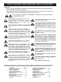
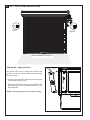
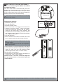
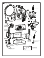
www.chamberlainanz.com
MR1000
Rolling Garage Door Opener
Installation and Operating Instructions
Owners Copy: Please keep these instructions for future reference
This manual contains IMPORTANT SAFETY information.
DO NOT PROCEED WITH THE INSTALLATION BEFORE READING THOROUGHLY.
START BY READING THESE IMPORTANT SAFETY INSTRUCTIONS
WARNING
• Failure to comply with the following instructions may result in serious personal injury or property damage.
• Read and follow all instructions carefully.
• The garage door opener is designed and tested to offer safe service provided it is installed and
operated in strict accordance with the instructions in this manual.
These safety alert symbols mean WARNING : A possible risk to personal safety or
property damage exists.
Keep garage door balanced. Do not let the
garage door opener compensate for a binding or
sticking garage door. Sticking, binding or
unbalanced doors must be repaired before
installing this opener.
Do not wear rings, watches or loose clothing
while installing or servicing a garage door
opener.
Frequently examine the door installation, in
particular cable, springs and mountings for
signs of wear, damage or imbalance. Do not use
if repair or adjustment is needed since springs
and hardware are under extreme tension and a
fault can cause serious personal injury.
To avoid serious personal injury from
entanglement, remove all ropes, chains and
locks connected to the garage door before
installing the door opener.
Installation and wiring must be in compliance
with your local building and electrical codes.
The safety reverse system test is very
important. Your garage door MUST reverse on
contact with a 40mm obstacle placed on the
floor. Failure to properly adjust the opener may
result in serious personal injury from a closing
garage door. Repeat the test once a month
and make any necessary adjustments.
This opener should not be installed in a
damp or wet space exposed to weather.
This appliance is not intended for use by
persons (including children) with reduced
physical, sensory or mental capabilities or lack
of experience and knowledge, unless they have
been given supervision or instruction concerning
use of the appliance by a person responsible for
their safety.
The opener must not be used on a wicket
door (door within a door).
The Protector SystemTM must be used for
all installations where the closing force as
measured on the bottom of the door is
over 400N (40kgf). Excessive force will
interfere with the proper operation of the
safety reverse system or damage the garage
door.
After installation, ensure that the parts of
the door do not extend over public
footpaths or roads.
Install the wireless wall control (or any
additional wall control) in a location where
the garage door is visible, at a height of at
least 1.5m and out of the reach of children.
Do not allow children to operate push
button(s) or transmitter(s). Serious personal
injury from a closing garage door may result
from misuse of the opener.
Permanently fasten the Warning Labels in
prominent places, adjacent to wall controls
and manual release mechanisms as a
reminder of safe operating procedures.
Activate opener only when the door is in
full view, free of obstructions and the
opener is properly adjusted. No one
should enter or leave the garage while the
door is in motion.
Do not allow children to play near the door,
or door controls.
Disconnect electric power to the garage
door opener before making repairs or
removing covers.
KEEP THESE INSTRUCTIONS
NOTE: If your garage has no service entrance door, a CM1702 outside quick release must be installed.
This accessory allows manual operation of the garage door from outside in case of power failure.
CONTENTS
PAGE
SAFETY INSTRUCTIONS . . . . . . . . .1
CARTON INVENTORY . . . . . . . . . . . .2
TOOLS REQUIRED . . . . . . . . . . . . . .2
DOOR REQUIREMENTS . . . . . . . . . .2
PREPARE & TEST THE DOOR . . . . .3
RELEASE CORD . . . . . . . . . . . . . . . .4
INSTALLATION . . . . . . . . . . . . . . . .5-7
CONNECT ELECTRIC POWER . . . . .7
ADJUSTMENT . . . . . . . . . . . . . . . .8-9
INSTALL THE PROTECTOR
SYSTEM . . . . . . . . . . . . . . . . . . . . . .10
SETTING AUTO-CLOSE . . . . . . . . .11
WIRELESS PROGRAMMING . . .12-13
SPECIAL FEATURES . . . . . . . . . . . .14
ACCESSORIES . . . . . . . . . . . . . . . .14
SPARE PARTS . . . . . . . . . . . . . . . . .15
TROUBLESHOOTING . . . . . . . .16-17
OPERATION OF YOUR OPENER . .18
CARE OF YOUR OPENER . . . . . . .18
MAINTENANCE OF YOUR
OPENER . . . . . . . . . . . . . . . . . . . . . .18
SPECIFICATIONS . . . . . . . . . . . . . .18
WARRANTY . . . . . . . . . . . . . . . . . . .19
1
2 TOOLS REQUIRED
1 CARTON INVENTORY
1. Instruction manual (this document)
2. Stop collar
3. Drive forks
4. Release handle and cord
5. Transmitter (2)
6. Wireless wall control
7. Hardware bag
8. Weight bar
9. Warning label and risk of entrapment label
10.Lamp cover
1
2
4
5
1. Ladder
2. Adjustable wrench for U-bolts already installed
on the door
3. 8mm socket, 10mm socket and 13mm extended
socket and socket wrench
4. 12inch socket extension (for minimum side-room
installations)
5. Drill and 5.5mm drill bit
6. Phillips-head screwdriver
7. Marker pen
3
7
6
8
10
9
3 DOOR REQUIREMENTS
The maximum allowable door height is 3m with a maximum curtain area of 16.5m²* (door height in metres
multiplied by the width in metres). The door must be spring balanced.
*The Protector System™ (IR Beams) must be installed if the force at the edge of the closing door exceeds 400N
(40kgf), or if the door exceeds a mass of 130kg. Door axle diameter must not exceed 35mm.
270mm
135mm
130mm
70mm
160mm
40mm
58mm
51mm
420mm
220mm
160mm
166mm
2
4 TESTING THE DOOR
Disable all locks and remove any ropes connected to
the garage door.
Complete the following test to ensure your door is well
balanced, and not sticking or binding:
• Lift the door to about halfway and then release it. The door
should remain spring balanced.
NOTE: The spring should hold the door at any open
position without creeping up or down.
• Raise and lower the door to discover if there are any
sticking or binding points.
• If your door does not hold in place or the door binds or
sticks, call a qualified door technician before automating
the door.
5 INSTALLING THE STOP COLLAR
• Install the stop collar on the opposite end to where the
opener is to be installed.
• Fit the stop collar hard against the boss of the door
drum. Ensure the U-bolt holding the door axle to the door
bracket is tightly secured.
SAFETY CHECK!
Is the stop collar
installed?
YES: proceed to the next
step
NO: install the stop collar
before proceeding
6 INSTALLING THE WEIGHT BAR (PROVIDED)
• Place the weight bar in the centre of the door.
• If the door curtain does not have a lifting handle you
will need to drill two 5.5mm holes through the two
marked positions, then place the weight bar on the
inside of the door.
• Use the 5mm bolts, washers and nuts (provided) to
fasten the weight bar in place.
NOTE: If the door has a lifting handle, remove the
handle, nuts & bolts. Place weight bar over the
handle holes, insert extended bolts through the
weight bar & fasten handle back in place.
3
7 ATTACHING THE RELEASE HANDLE AND CORD
• Thread one end of the rope through the hole in the top of the
red handle so “NOTICE” reads right side up as shown.
• Secure with an overhand knot at least 25mm from the end of
the rope to prevent slipping.
• Thread the other end of the rope through the loop of red
clutch lever.
• Adjust rope length so the handle is no higher than 1.8m
above the floor. Secure with an overhand knot. If the door is
greater than 2.5m in height the release cord extension kit
accessory is required.
NOTE: Final adjustment of handle height should be
completed after the opener is installed. If it is necessary
to cut the rope, heat seal the cut end to prevent
unravelling (refer section 16).
Overhand knot
Start / stop
activation button
Manual release
warning label
Rope
Release handle
8 OPERATING THE MANUAL RELEASE
To disengage the opener
fig 2
fig 1
Pull the release cord down firmly until the
red clutch lever reaches the bottom stop
(fig 1).
To re-engage the opener
Push the red lever up until the red clutch
lever reaches the top stop (fig 2).
Disengaged
Engaged
Disable all locks and remove any ropes connected to the garage door.
Take care when operating the manual release as an open door may fall rapidly due to weak or
broken springs, or being out of balance.
4
9 PINNING THE DOOR
NOTE: A ballooning door may delay the safety reversal
response and can compromise garage door security.
• To remedy any ballooning, place self tapping metal screws or
rivets where the curtain leaves the roll. Secure these
through the curtain into the drum wheel at each end of the
roll.
Free curtain
Ballooning
Add fasteners here
• After determining the correct fastener location as shown, lift
the door approximately half a turn from the closed position
to allow access for drilling.
Door closed
Door can be lifted
Door secure
10 ATTACHING DRIVE FORKS
NOTE: For standard installations the drive forks should be located on the lower holes as shown.
• Insert the two hex head bolts provided
through the two holes closest to the axle
as illustrated.
• Place the drive forks over the bolts.
• Place the two spring washers provided
over the bolts and thread the two nuts
onto the bolts as illustrated and tighten.
• Attach the lamp cover to the bottom of
opener as shown.
5
11 LEFT / RIGHT HAND INSTALLATION
roller:L
roller:L
roller:L
roller:L
R
R
LEFT
RIGHT
Inside garage looking out
Setting left / right operation
fig 1
The opener must be set to either left or right hand
operation via the dip switch located under the green
activation button.
roller:L
roller:L
R
R
open
180s
60s
timer to
close
• Gently pry the flap down and away from the opener
using a screw driver or pen.
0s/off
operate
• Adjust the two direction dip switches located under
the green plate to “R” for right hand doors or “L” for
left hand doors.
close
NOTE: Leave green plate off for control setting.
6
132A2663
learn
R
R
12 INSTALLATION PROCEDURE
Do not allow people to walk under or around
the door during the installation process.
Serious injury can occur.
NOTE: The opener can be installed on either side
of the door. The following instructions are for
RIGHT HAND INSTALLATIONS (as illustrated i.e.
inside the garage looking out). For left hand
installations, reverse the instruction terminology
(eg LEFT for RIGHT etc).
Rope
Door Stand
Preparation:
• Place the opener in manual release mode (refer
section 8).
• Open the roller door fully. For safety, tie a rope
around the door.
• Ensure the door axle U-bolt and door mounting
bracket on the left hand side (non opener side) are
securely fastened.
• Support the door with a door stand or similar device
to safely support the door.
• Mark the position of the door axle on the right hand
door bracket (for reassembly purposes).
• While the door is supported, remove the right hand
axle U-Bolt and door mounting bracket from the wall.
Install the opener:
• Slide the opener over the door axle and engage the
drive forks into the door drum wheel, either side of a
support spoke.
• Refit the door mounting bracket to the wall and the
U-bolt to the axle. If the door bracket needs to be
relocated due to opener width, the dimensions in
section 3 can assist.
• Position the opener assembly vertical to the floor.
• Clamp the opener on the door axle using the cone
tipped hex bolts supplied in the mounting collar.
• Remove all ropes and the support stand.
Rope
Door Stand
Ensure that mounting bolts are adequately
tightened (i.e. 25– 28Nm) to avoid any
movement on the door axle.
• Check the operation of the door in manual mode by
raising and lowering by hand. It should operate
smoothly with no obstructions. The disengage
handle should already be attached less than 1.8m
above the floor gap.
Connect the power
• Position the power cable away from the door curtain
and any moving parts.
• Plug the opener into a nearby power point and turn
ON (opener courtesy lamp should turn ON).
• The opener must now be programmed for:Door travel limits
(section 13)
Force setting
(section 14)
7
13 SETTING THE LIMITS FOR RIGHT OR LEFT OPERATION
The travel limits regulate the points at which the door will stop when moving UP or DOWN.
The procedure for setting these limits differs depending on which side of the garage door the opener has been
fitted. eg As viewed from inside the garage looking out, is the opener on the right-hand or left-hand side.
The opener must be fully installed on the door and all installation steps completed before proceeding.
Make sure the door is clear of obstruction. Ensure your hands are away
from any moving parts before activating the door.
NOTE: Remove the limit switch cover screw and open panel (fig1) to
expose the limit actuator arms panel from the right front face of the
opener. Remove the green control panel cover from the left front face of
the opener (see fig1 section 11)
fig 1
SETTING DOOR TRAVEL LIMITS FOR RIGHT HAND-MOUNTING
Step 1:Inspect the option switches on the control panel. Both switches marked roller should
position.
Step 2: Set the bottom limit of travel
Connect the mains power to the opener and switch the
power on. Pull the manual release to disengage the
door from the opener. Lower the door manually to the
fully closed position. Observe the red LED marked
close on the control panel. Rotate the front limitactuator-arm anti-clockwise until it contacts its
microswitch and the red LED stays on continuously.
Step 3: Set the upper limit of travel
Raise the door manually to the fully open position.
Observe the amber LED marked open on the control
panel. Rotate the rear limit-actuator-arm clockwise until
it contacts its microswitch and the amber LED stays on
continuously.
Step 4: Fine adjustment
Although the limits are essentially set in the correct
position, the door travel can be further adjusted using
the fine adjustment screws. Each turn of the screw
results in around 5mm of door travel.
Confirm the limits are set correctly by engaging the
manual release (see section 8), then closing and
opening the door using the green operate button.
Repeat the above steps if required.
be moved to “R”
Travel limit
actuator arms
Fine Adjustment
Microswitches
The force must now be set in order to complete your installation, see section 14.
SETTING DOOR TRAVEL LIMITS FOR LEFT-HAND MOUNTING
Step 1: Inspect the option switches on the control panel. Both switches marked roller should be moved to “L”.
Step 2 : Set the bottom limit of travel
Connect the mains power to the opener and switch the power on. Pull the manual release to disengage the
door from the opener. Lower the door manually to the fully closed position. Observe the red LED marked close
on the control panel. Rotate the rear limit-actuator-arm clockwise until it contacts its microswitch and the red
LED stays on continuously.
Step 3: Set the upper limit of travel
Raise the door manually to the fully open position. Observe the amber LED marked open on the control panel.
Rotate the front limit-actuator-arm anti-clockwise until it contacts its microswitch and the amber LED stays on
continuously.
Step 4: Fine adjustment
The limits are essentially set in the correct position. However the door travel can be further adjusted using the
fine adjustment screw. Each turn of the screw results in around 5mm of door travel.
Confirm the limits are set correctly by engaging the manual release (see section 8). Close and open the door
using the green operate button. Repeat the above steps if required.
The force must now be set in order to complete your installation, see section 14.
8
14 SETTING THE FORCE
Setting the force
The force, as measured on the closing edge of the door,
should not exceed 400N (40kgf). If the closing force is
measured to more than 400N, the Protector SystemTM
must be installed (refer section 17). The force setting
regulates the amount of power required to open and
close the door.
This procedure requires the door to be engaged (see
section 8) and run through one full cycle of
operation.
operate
Press learn
button twice
learn
x2
close
open
Step 1: Start with the door in the fully open position and
the green control panel cover should be removed (see fig
1 section 11). Press the red learn button twice on the
control panel to enter into the force learn mode. The
amber LED marked open on the control panel will flash
quickly.
Step 2: Press the green operate button on the control
panel. The door will travel to the DOWN limit. Press the
operate button again, the door will travel to the UP limit.
The amber LED marked open on the control panel will
stop flashing when the force has been learned.
operate
LED will start flashing
Press OPERATE
button (door will close)
learn
Press OPERATE
button to open the
door
open
LED will turn off
15 TESTING THE SAFETY REVERSE SYSTEM
The safety reverse system test is important. The
garage door must reverse on contact with a
40mm obstacle laid flat on the floor. Failure to
properly adjust the opener may result in serious
personal injury from a closing garage door.
40mm
Place a 40mm obstacle on the floor. Operate the door in
the down direction. The door must reverse upon contact
with the obstruction. If the door stops on the obstruction,
remove obstruction and repeat limit and force setting
(refer sections 13 and 14).
Repeat test of the safety reverse system.
40mm Test obstacle
16 FIXING WARNING LABELS
Once you have completed your installation and
successfully carried out the safety reverse system test
outlined above. Install the warning labels provided with
your opener.
Ensure the manual release instruction card is attached to
the rope as detailed in section 7.
Read the safety instructions (page 1) for further details
concerning safety.
9
> 1.5m
The WARNING label must be installed in a prominent
place near any fixed control.
Any fixed wall control or wireless door control must be
mounted at a height of no less than 1.5m out of the
reach of children.
Release handle should
be less than 1.8m
above the ground
< 1.8m
Ensure the risk of entrapment label is installed adjacent
to the release handle at height of less than 1.8m from the
floor.
Wireless wall buttons, or
wall controls.
No less than 1.5m from
ground
Ground level
17 INSTALL THE PROTECTOR SYSTEM™ (IR BEAMS)
SAFETY FIRST!
Whilst Chamberlain have engineered safety features into your garage door opener, we urge you to consider
fitting IR Beams to your new garage door opener. In many countries these devices are compulsory to prevent
serious injury or property damage. For your own peace of mind and the safety of others please install this
inexpensive safety device.
Install this accessory for all installations where the closing force as measured on the bottom of the door is over
400N (40kgf), or if the door exceeds a mass of 130kg.
After the opener has been installed and adjusted, the Protector System™ accessory can be installed.
Instructions are included with this accessory.
The Protector System™ provides an additional measure of safety against a small child or animal being
trapped under a garage door. It uses an infra-red beam, which when broken by an obstruction, causes a
closing door to open and prevents an open door from closing and is strongly recommended for homeowners
with young children.
NOTE: The opener will automatically detect the Protector SystemTM when it is installed and operating
for 5 minutes (during this time the beams must remain unobstructed). The opener will not close unless
the beams are aligned.
IR Beams must be installed
to detect a 100mm high
obstacle at any point along
the floor.
Red LED
MUST BE ON
Red LED
MUST BE ON
IR Beam
IR Beam
10
18 SETTING AUTO CLOSE (OPTIONAL)
NOTE: The Protector SystemTM MUST be installed
to enable this feature.
The auto close feature will automatically close the
garage door after the preset time. The time can be
adjusted up to 180 seconds using the trim pot located
on the control board. Auto close can be disabled by
adjusting the trim pot to the 0s/off setting.
Terminals Located
under flap.
Remove lamp cover:
Auto close is NOT recommended for households
with young children.
Installing and adjusting:
• Close the garage door.
• Turn the opener off.
• Remove the lamp cover.
• Ensure the trim pot on the opener is set to the 0s/off.
• Install the Protector SystemTM using the brackets,
wires and instructions provided with the product.
Twist the two white (only) wires together and
terminate them into the white (2) terminal. Twist the
two white/black wires together and terminate them
into the grey (3) terminal.
• Turn the opener on.
• Allow 5 minutes for the beams to self-learn to the unit
(do not walk through the beam during this time).
manual control
12Vdc
+
Do not adjust the trim pot whilst the door is in the
open position.
Door will activate when the trim pot is adjusted in
the open position
roller:L
roller:L
2
com
3
IR
1
P/B
remove
for setup
R
R
open
180s
• Ensure the door is in the closed position, then adjust
the trim pot to the desired closing time by turning the
“timer to close” trim pot anti-clockwise (label
indicates approximate Timer To Close values).
Test the timer close feature:
• Once the timer is set open the door and allow it to
close via the “timer to close” feature.
NOTE: If more or less time is desired, adjust the
trim pot whilst the door is closed then repeat test
outlined above.
60s
timer to
close
0s/off
operate
close
132A2663
learn
manual
control
Door may operate unexpectedly, therefore do not allow anything to stay in the path of the door.
11
19 INSTALLING YOUR CM128 WIRELESS WALL BUTTON
Disconnect power to the opener whilst installing
this accessory to prevent accidental activation.
Locate minimum 1.5m above the floor.
To install:
• Carefully pry open the CM128 and locate the two screws for
mounting.
• Attach to the wall using the two screws and wall anchors
provided if mounting to a plaster wall. If using a recessed wall
box do not use anchors.
+
+
+
NOTE: Do not overtighten screws. The wall button supplied with your opener is pre-programmed to
your opener in the factory. If adding a new wall button, follow the steps below.
20 WIRELESS PROGRAMMING
Activate the opener only when door is in full view, free of obstruction and properly adjusted. No one
should enter or leave garage whilst door is in motion. Do not allow children to operate push
button(s) or transmitter(s). Do not allow children to play near the door.
Fix any wall control at a height of at least 1.5m and within sight of the door but away from any
moving parts.
NOTE: The transmitters supplied with your opener are preprogrammed to your opener in the factory. If you purchase
additional transmitters, you will need to program them into
your opener using the steps below.
• Fix the warning against entrapment label near the
wall control (see section 16).
ADDING transmitters using the learn button
TO ADD Transmitters / Wall Control
or
Press and hold down the desired
button.
open
NOTE : Door should be in the closed or in the midway
position to ensure the LED is off before you commence
programming.
operate
learn
• Press and hold down the transmitter button you wish to program
to the opener.
• The orange LED will flash continuously to indicate it is receiving
signal from the transmitter.
• Press and release the learn button on the opener.
• The courtesy light will flash once.
• Ensure the door is clear of obstruction, then test the transmitter.
LED will flash continuously
Press and release
the red learn button
close
Courtesy light will
flash once
Deleting ALL transmitters and codes
TO DELETE ALL TRANSMITTERS
NOTE: This deletes all transmitters and codes.
operate
learn
• Press and hold the LEARN button until the orange indicator light
goes out (approximately 9 sec).
Press and
hold the red
learn button
close
12
open
LED will light up
open
LED will go out
after (approx) 9
seconds. Release
learn button
21 KEYLESS DEVICE PROGRAMMING (OPTIONAL ACCESSORY)
Programming C840 using the “learn” button:
1
Activate the opener only when door is in full view, free of
obstruction and properly adjusted. No one should enter
or leave garage while the door is in motion. Do not allow
children to operate push button(s) or transmitter(s). Do not
allow children to play near the door.
operate
Press and release
the red learn button
learn
close
1. Press and release the “learn” button (1) on opener. The orange
learn indicator LED will light up.
2. Within 30 seconds, enter a four digit personal identification
number (PIN) of your choice on the keypad (2), then press and
hold the ENTER button.
3. Release the button when the opener courtesy light flashes once
(3). It has learned the code.
open
LED will light up
2
Enter 4 digit PIN at
keypad (within 30s)
3
Courtesy light will
flash once
Alternate programming method using the motion detecting
control panel (optional accessory):
NOTE: This method requires two people if the keyless entry is
already mounted outside the garage.
1
1. Enter a four digit personal identification number (PIN) of your
choice on the keypad, then press and hold ENTER.
2. While holding the ENTER button, press and hold the LIGHT
button on the motion detecting control panel.
3. Continue holding the ENTER and LIGHT buttons while you
press the push bar on the motion detecting control panel (all
three buttons are held).
4. Release buttons when the opener courtesy light flashes once.
2
Enter 4 digit PIN at
keypad (within 30s)
Press and hold down
LIGHT button on the
motion detecting
control panel
LIGHT
LOCK
3
With the LIGHT button
pressed, press and
hold the PUSH BAR on
the motion detecting
control panel
LOCK
LIGHT
4
Release buttons
when light flashes
Programming C379 wireless fingerprint access
system (optional accessory)
operate
learn
Full instructions are available with this accessory.
Once you have enrolled your user into the C379 you can
program the unit into your opener.
Press and release
the red learn button
close
open
LED will light up
Using the “learn” button:
1. Press and release the learn button on the opener. The learn
indicator LED on the opener will light up.
2. Within 30 seconds, slide the cover of the C379 up as illustrated
(A). Swipe your finger on the reader head at a steady speed (B)
until the yellow led turns on (C).
3. When the openerʼs courtesy light flashes it has learned the
code. Ensure there are no obstructions in the path of the door,
then press the send button (D) to test the door.
A
ENROLL
SEND
ENROLL
PASS
FAIL
READY
RETRY
Slide the cover plate
up (A)
B
Swipe finger at a
steady speed (B)
C
ENROLL
SEND
ENROLL
PASS
FAIL
READY
RETRY
Yellow LED will indicate
successful swipe (C)
Courtesy light will
flash once
D
Test reader by pressing
the send button (D)
13
22 SPECIAL FEATURES (OPTIONAL ACCESSORIES)
1. Power output for external devices
(12Vdc 100mA).
2. The Protector SystemTM (C77 IR Beams).
3. Multi-function wall control (C98).
manual control
red
white
12Vdc
+
2
com
3
1
IR
P/B
External
Device
100ma (max)
12vdc
gnd
no
rx
white
white/ black
com
Keyswitch or
push button
white
white/ black
23 ACCESSORIES
(1) Model CM844
(2) Model CM128
(3) Model C940
(4) Model C943
(5) Model C945
(6) Model 75LM
(7) Model C98
(8) Model C840
(9) Model C77
(10) Model CM1702
(11) Model 760E
(12) Model C379
4 Channel transmitter
Wireless wall button
Single channel transmitter
3 Channel transmitter
3 Channel mini transmitter
Illuminated door bell push button
CM844
2
1
C840
C940
CM128
C1702
C77
4
ENROLL
PASS
FAIL
READY
RETRY
12
14
LOCK
LIGHT
ENROLL
SEND
C98
6
5
11
9
75LM
C379
760E
10
8
C945
C943
3
Motion detecting control panel
Keyless entry system
The Protector SystemTM
Quick release lock
Outside keyswitch
Wireless fingerprint access system
7
24 SPARE PARTS
Drive forks
ADR2 0164
Motor assy
PDR5 0098
Drive gear cover
093A0533
Capacitor
203D1720
Main drive gear
/ limit assy
PDR4 0881
PCB loom
001A7086
Surge arrest
001A7089
RPM Sensor
001B 7089
Clutch assy
PDR5 9000
Side cover
CDR1 0695
Lamp Holder
217H 0375
Chassis assy
PDR5 9001
Chassis cover
PDR5 9002
Control cover
CCV1 2525
Side cover
CDR1 0695
Lamp cover
CDR1 0958A
Handle/ pull rope
PDR5 0091A
PCB assy
PDR5 9003
Hardware bag
PDR4 0735B
Terminal cover
PDR5 9004
15
DIAGNOSTIC CHART
1 FLASH
Safety reversing sensors
wire open (broken or
disconnected).
OR
2 FLASHES
Safety reversing sensors
wire shorted or black/white
wire reversed.
3 FLASHES
Door control or
wire shorted.
4 FLASHES
Safety reversing sensors
slightly misaligned
(dim or flashing LED).
5 FLASHES
Possible RPM sensor
failure. Unplug to reset.
6 FLASHES
Possible limit switch
error on start up.
10 to 15 FLASHES
System failure
Symptom: One or both of the indicator lights on the IR Beams are not on
steadily.
• Inspect sensor wires for an electrical short (eg. staple in wire), correct wiring polarity
(black/white wires reversed), broken or disconnected wires, replace/attach as
needed.
• Disconnect all wires from the opener.
• Remove beams from brackets and shorten sensor wires to 30-60mm (1-2”) from
back of each sensor.
• Re-attach sending eye to opener using shortened wires. If sending eye indicator
light glows steadily, attach the receiving eye.
• Align beams. If the indicator lights glow, replace the wires for the beams. If the
sensor indicator lights do not light up, replace the IR Beams.
Symptom: LED is not lit on door control.
• Check polarity of the wire connection to the opener.
• Inspect door control/wires for an electrical short (eg. staple in wire), replace as
needed.
• Disconnect wires at door control, touch wires together. If opener activates, replace
door control.
• If opener does not activate, disconnect door control wires from opener. Momentarily
short across red and white terminals with jumper wire. If opener activates, replace
door control wires.
Symptom: Sending indicator light glows steadily, receiving indicator light is
dim or flashing.
• Realign receiving eye sensor, clean lens and secure brackets.
Symptom: The RPM Sensor = Short travel 150-200mm (6-8").
• Unplug unit to reset. Try to operate opener. Check diagnostic code.
• If it is still flashing 5 times and opener moves 150-200mm (6-8"), the RPM sensor
may need to be replaced, for details contact your Chamberlain Merlin Professional
Dealer.
Symptom: Door will not open or close
• Turn the power off. Wait 10 seconds.
• Turn power back on. If opener fails to operate correctly after resetting, contact your
Chamberlain Merlin Professional Dealer.
Symptom: Opener will not open or close the door
• Turn the power off. Wait 10 seconds.
• Turn power back on. If opener fails to operate correctly after resetting, contact your
Chamberlain Merlin Professional Dealer.
• Contact your Chamberlain Merlin Professional Dealer.
(report the number of flashes as the fault reference).
16
TROUBLESHOOTING
1. The opener doesn't operate from either the
ACTIVATION button or the transmitter:
• Does the opener have electric power? Plug a lamp into the
outlet. If it doesn't light, check the fuse box.
• Have you disabled all door locks? Review installation
instruction warnings on page 1.
• Is there a build-up of ice or snow under the door? The door
may be frozen to the ground. Remove any restriction.
• The garage door spring may be broken. Have it replaced.
2. Opener operates from the transmitter, but not
from the wired wall control (optional accessory):
• Is the wall control lit? If not, reverse the two wires. If the
opener runs, check for a faulty wire connection at the wall
control, a short under the staples, or a broken wire.
• Are the wiring connections correct? Refer to wired wall
control instructions.
3. The door operates from the ACTIVATION button or
wired wall control, but not from the wireless wall
control or transmitter:
• If the wired wall control is installed and it is flashing, ensure
the lock feature is off.
• Program the opener to match the transmitter code. (Refer
to section 20). Repeat with all transmitters.
4. The transmitter has short range:
• Change the location of the transmitter in your car.
• Check to be sure the antenna on the bottom of the opener
extends fully downward.
• Some installations may have shorter range due to a metal
door, foil backed insulation, or metal garage siding.
• Replace transmitter batteries.
5. The garage door opens and closes by itself:
• Be sure that all transmitter push buttons are off.
• If the wired wall control (optional accessory) is installed,
remove the bell wire from the wired wall control terminals
and operate from the ACTIVATION button or transmitter.
If this solves the problem, the wired wall control is faulty
(replace), or there is an intermittent short on the wire
between the wired wall control and the opener.
• Clear memory and re-program all wireless wall controls
and transmitters.
6. The door will stop, reverses slightly away from the
obstruction then stop:
• Is something obstructing the door? Is it out of balance, or
are the springs broken? Remove the obstruction or repair
the door.
7. The door reverses for no apparent reason and
opener light flashes for 5 seconds after reversing:
• Check the Protector SystemTM (IR Beams), if installed
Correct alignment if the red light on the beam is solid.
8. The door opens but won't close or reverses while
closing:
• Is something obstructing the door? Pull the manual
release handle. Operate the door manually. If it is
unbalanced or binding, call a trained door systems
technician.
• Clear any ice or snow from the garage floor area where
the door closes.
• Repeat the limit and force setting in section 13 and section
14. Repeat safety reverse test after adjustments.
9. The opener strains to operate door:
• The door may be out of balance or the springs may be
broken. Close the door and use the manual release to
disconnect the door. Open and close the door
manually. A properly balanced door will stay in any
point of travel while being supported entirely by its
springs. If it does not, disconnect the opener and call a
trained door systems technician.
10. The opener hums briefly, then won't work:
• Check that the door is not in manual release mode,
refer section 8.
• The garage door springs may be broken. See above.
• If the problem occurs on the first operation of the
opener, door may be locked. Disable any door locks.
11. The opener won't operate due to power failure:
• Use the manual release handle to disconnect the door. The
door can be opened and closed manually. When power is
restored, re-engage the opener, refer section 8.
12. The opener flashes once every minute for 10
minutes after operating (optional feature):
• Door and opener requires service. Contact your local
Chamberlain Merlin dealer.
17
OPERATION OF YOUR OPENER
CARE OF YOUR OPENER
Your opener can be activated by any of the following
devices:
When properly installed, your opener will operate with
minimal maintenance. The opener does not require
additional lubrication.
• The ACTIVATION (START/STOP) button
Press the button until door starts to move.
Limit and force settings: These settings must be
checked and properly set when the opener is installed.
Weather conditions may cause some minor changes in
the door operation, requiring some re-adjustments,
particularly during the first year of operation. Refer to
limit and force setting in, sections 13 & 14.
• The wall control, outside keylock or keyless
entry system (if you have installed any of these
accessories).
Follow the instructions carefully and repeat the
• The transmitter or wireless wall
safety reverse test after any adjustment.
button (CM128)
Hold the push button down until the door starts to move. Transmitter:
Additional transmitters can be purchased at any time.
When the opener is activated by transmitter,
Refer to accessories. Any new transmitters must be
ACTIVATION button or wall control:
programmed into the opener.
• If open, the door will close. If closed, the door will open.
• If closing, the door will stop.
• If opening, the door will stop (allowing space for entry
and exit of pets and for fresh air).
• If the door has been stopped in a partially open or
closed position, it will reverse direction.
• If an obstruction is encountered while closing, the door
will stop, then reverse.
• If an obstruction is encountered while opening, the door
will stop, reverse away from the obstruction then stop.
• The optional Protector System™ uses an invisible beam
which, when broken by an obstruction, causes a closing
door to open and prevents an open door from closing. It
is STRONGLY RECOMMENDED for homeowners with
young children.
Transmitter battery:
If transmission range decreases, replace the battery.
MAINTENANCE OF YOUR OPENER
Once a month:
• Repeat safety reverse test.
Make any necessary adjustments (sections 13 & 14)
• Manually operate door. If it is unbalanced or binding,
call for professional garage door service.
• Check to be sure door opens and closes fully.
Set limits and/or force if necessary.
Once every 3 months:
• Ensure that mounting bolts are adequately tightened
(i.e. 25-28Nm) to the door axle.
Allow a 15 minute cooling period after 4 minutes of
continuous operation of the opener.
SPECIFICATIONS MR1000
Opening the door manually: (refer section 8)
Input Voltage:
230-240VAC, 50Hz, 460W
Rated Load:
50Nm
Max.Pull Force:
700N
Max. Door Mass:
130kg (spring balanced)
Idle Current:
less than 5mA @ 230VAC
The door can be opened manually by pulling the release
cord down firmly.
To re-connect the door, push the red clutch lever up to
the top stop position.
Drive:
AC gearmotor
Max. Drum Rotations:
3
Memory Registers:
64
The opener light will turn on:
• when the opener is initially plugged in;
• after the power has been briefly interrupted;
• when the opener is activated.
(the light turns off automatically after 2-1/2 minutes.)
Operating Frequency:
433.92MHz AM Peak Detect
rolling code.
Auxillary power output:
12VDC 100ma (max)
Door should be fully closed if possible. Weak or
broken springs could allow an open door to fall
rapidly. Property damage or serious personal injury
could result.
SPECIAL NOTE: Chamberlain strongly recommends that the Protector SystemTM be installed on all garage door openers.
18
CHAMBERLAIN LIMITED WARRANTY
Merlin Professional MR1000
Rolling Garage Door Opener
Chamberlain Australia Pty Limited / Chamberlain New
Zealand Limited (Seller) warrants to the original
purchaser of the Chamberlain MR1000 Roller Door
Opener (Unit) that it is free from defects in material
and/or workmanship for a period of 2 YEARS from the
date of first purchase from the Seller. The MR1000 motor
(only) has a 5 year warranty from date of first purchase
from the seller when installed on a domestic door.
Please retain your proof-of-purchase in the unlikely event
you require warranty service.
If, during the limited warranty period, the Unit fails due to
defects in materials or workmanship Chamberlain will,
provided the defective part or Unit is returned freight and
insurance prepaid and well packaged to the nearest
Chamberlain office or authorised installer, undertake to
repair or, at its option, replace any defective part or Unit and
return it to the Buyer at no cost. Repairs and replacement
parts are warranted for the remaining portion of the original
warranty period.
Limited warranty on opener
Chamberlain will furnish a replacement opener free of
charge, if it is found to be defective. Labour costs may apply.
Where the Unit has been installed by an authorised installer,
Chamberlain will furnish replacement parts free of charge
through the authorised installer. A service fee for on-site
service may apply.
In-warranty service
During the warranty period, if the product appears as though
it may be defective, call our toll free service before removal
of the Unit. A Chamberlain technician will diagnose the
problem and promptly supply you with the parts for “do-ityourself” repairs, or provide you with shipping instructions for
a factory repair or replacement. If an authorised installer
installed your Unit you must call them for prompt on-site
service.
If our service centre determines that a warranty claim has
been made in respect of a failure or defect arising out of any
exclusion detailed below, we may charge you a fee to repair
and/or return the Unit to you.
Exclusions
This warranty does not cover any failure of the Unit due to:
1. non-compliance with the instructions regarding
installation, operation, maintenance and testing of the Unit or
of any product with which the Unit is used.
2. any attempt to repair, dismantle, reinstall or move the
Product to another location once the Product is installed by
any person other than an authorised installer.
3. tampering, neglect, abuse, wear and tear, accident,
electrical storm, excessive use or conditions other than
normal domestic use.
This warranty does not cover any problems with, or relating
to, the garage door or garage door hardware, including but
not limited to the door springs, door rollers, door alignment
or hinges, any problems caused by electrical faults,
replacement of batteries or light bulbs or labour charges for
reinstalling a repaired or replaced Units.
Liability – Australia only
Under no circumstances shall the Seller be liable for
consequential, incidental or special damages arising in
connection with the use, or inability to use, the Unit. In no
event shall the Seller's liability for damages or injury arising
from breach of law or contract or for negligence, exceed the
cost of repairing or replacing the Unit or refunding the
purchase price of the Unit.
Under Division 2 Part V of the Trade Practices Act, 1974,
certain warranties and conditions (Implied Terms) are implied
into contracts for the supply of goods or services if the goods
or services are of a kind ordinarily acquired for personal,
domestic or household use or consumption. Liability for
breach of those Implied Terms cannot be excluded or limited
and the limitations and exclusions above do not apply to the
Implied Terms.
Except for the Implied Terms and the warranties set out
above, the Seller excludes all warranties and conditions
implied by statute, at law, in fact or otherwise.
Liability – New Zealand only
Except as set out in the Fair Trading Act 1986 and the
Consumer Guarantees Act 1993:
(a) all other guarantees, warranties and representations in
relation to the Unit or its supply are excluded to the extent
that the Seller can lawfully exclude them; and
(b) under no circumstances shall the Seller be liable for
consequential, incidental or special damages arising in
connection with the use, or inability to use, the Unit, other
than those which were reasonably foreseeable as liable
to result from the failure.
NOTE: We request that you attach your sales docket or
invoice to this manual to enable you to establish the date
of purchase in the unlikely event of a service call being
made. Chamberlain reserves the right to change the
design and specification without prior notification. Some
features or accessories may not be available in certain
markets or areas. Please check with your distributor.
CONTACT DETAILS:
Chamberlain service centres:
Australia
Phone toll free 1800 638 234
Fax toll free 1800 888 121
New Zealand
Auckland phone 09 477 2823
Phone toll free 0800 653 667
Fax toll free 0800 653 663
www.chamberlainanz.com
TM
Trademark of The Chamberlain Group, Inc.
® Registered Trademark of The Chamberlain Group, Inc.
© 2009 The Chamberlain Group, Inc
114A3791F
19