1
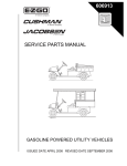
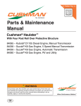
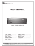
Bulletin No.
3B-05
!
ACTION REQUIRED
INFORMATION ONLY
ROUTINE MAINTENANCE
!
IMMEDIATE ACTION REQUIRED
(FIELD CAMPAIGN)
REVISED 3B
Subject:
Carburetor Update - MCI
Date:
11/29/2005
Units Affected:
MPT 800
COMMANDER 280
HAULER 800
INDUSTRIAL 800
WORKHORSE 800
TXT 2+2
TXT Gas
TXT Freedom
TXT Freedom HP
Serial No. Range: 2154517 - 2341629 (Manufacture date 11/03/03 - 07/01/05, see control cards)
Issue #1:
Fuel migration from carburetor
MANUFACTURER CHANGES
Resolution#1: New vehicles produced will have recommended parts installed at time of manufacturing.
FIELD MODIFICATIONS:See attached procedures. If any questions should arise please call 1-800241-5855 EXT. 4558.
* Kits will be provided at no charge based on information from the control cards.
Corrections should be submitted to ensure proper kit distribution. (Corrections
should be submitted to: [email protected] or faxed to: 1-800-448-8124)
Read and understand the following text and warnings before attempting installation.
To prevent an ignition spark which could ignite gasoline from the fuel system and
result in personal injury, the negative battery cable must be removed from battery.
Wrap wrenches with vinyl tape to prevent the possibility of a
dropped wrench from ‘shorting out’ a battery, which could
result in an explosion and severe personal injury.
E-Z-GO Division of Textron, Inc., 1451 Marvin Griffin Road, Augusta, Georgia
USA 30906-3852 Phone: 1-800-774-3946, FAX: 1-800-448-8124
Page 1
Bulletin No.
3B-05
AIR FILTER/ENGINE INSPECTION CHECKLIST
Turn key to off and remove the negative (-) battery cable at the battery to prevent the vehicle moving and the possible personal injury that may result.
1. Inspect governor / throttle system, repair or replace as required:
a. Inspect governor / throttle system to assure it has not been tampered with.
If tampering has occurred, reset or replace as required to factory
specifications.
b. Inspect governor cable to assure free travel without sticking
c. Inspect pedal box micro-switch to assure proper timing
Proper Micro Switch Adjustment
When the system is in correct adjustment, the micro switch in the accelerator pedal box will click when the top of
the accelerator pedal moves approximately 1/2" - 5/8" (13 - 16 mm). The accelerator cable (as seen at the rear
axle) should have some slack present and not show any movement until after the micro switch clicks.
d. Inspect throttle stop for proper closing
E-Z-GO Division of Textron, Inc., 1451 Marvin Griffin Road, Augusta, Georgia
USA 30906-3852 Phone: 1-800-774-3946, FAX: 1-800-448-8124
Page 2
Bulletin No.
3B-05
Subject: MCI Engine Modification
NOTE: REFERENCE PART NO. 604240
Read and understand the following text and warnings before attempting installation.
To prevent an ignition spark which could ignite gasoline from the fuel system and
result in personal injury, the negative battery cable must be removed from battery.
Wrap wrenches with vinyl tape to prevent the possibility of a
dropped wrench from ‘shorting out’ a battery, which could
result in an explosion and severe personal injury.
Cover the battery with a cloth or piece of old floormat to prevent the possibility of
‘shorting out’ from contact with other metal objects.
A. Starter/Generator Removal
1.
To prevent an ignition spark which could result in personal injury, the negative battery cable must
be removed from battery. Wrap wrenches with vinyl tape to prevent the possibility of a dropped
wrench from ’shorting out’ a battery. Cover the battery with a cloth or piece of old floormat to prevent the possibility of ‘shorting out’ from contact with other metal objects.
2.
Using a 3/4" socket and open end wrench, loosen the starter/generator pivot bolt. While holding the
adjusting nut with a 9/16" wrench, loosen the jam nut with another 9/16" wrench. See Figure 1.
Move the adjusting nut up the adjusting bolt until belt tension is relaxed and the starter/generator
belt can be removed.
3.
Using a 3/4" socket and open end wrench, remove the starter/generator pivot bolt nut and remove
the pivot bolt. There is no need to remove the wiring from the starter/generator. Move the starter/
generator out of the way of the front of the engine.
B. Carburetor Removal (See Figure 2)
1.
Remove the choke/throttle cover (17) by drilling out the rivets (16). Retain the washers for reassembly. Disconnect the solid linkage (8) from the carburetor throttle lever. Remove the choke cable (9)
from the choke lever swivel (10) on carburetor. See figure 2.
2.
Unsnap the three retaining clips (1) securing the cover (2) to the air box (3). Remove the cover and
remove the air filter element (4). Remove the hardware (11) connecting the airbox to the coil
bracket mount.
3.
Remove the PCV valve hose (5) from the rear of the air box.
4.
Remove the two nuts (12) securing the carburetor baffle and remove them both from the airbox.
E-Z-GO Division of Textron, Inc., 1451 Marvin Griffin Road, Augusta, Georgia
USA 30906-3852 Phone: 1-800-774-3946, FAX: 1-800-448-8124
Page 3
Bulletin No.
3B-05
Jam Nut
Adjusting Nut
Fig. 1 Adjusting the Belt Tension
5.
Remove the two nuts (12), lock washers (13) and double end studs (14) securing the airbox to the
carburetor. Retain the hardware for reassembly. Remove the air filter housing.
6.
Remove the choke bracket (15) and gaskets and slide the carburetor (7) from the engine studs.
Carefully lay the carburetor with hoses still attached to the side by the gasoline tank to be installed
later.
7.
Remove the remaining carburetor insulator and gaskets from the engine.
8.
Remove the two existing carburetor studs.
E-Z-GO Division of Textron, Inc., 1451 Marvin Griffin Road, Augusta, Georgia
USA 30906-3852 Phone: 1-800-774-3946, FAX: 1-800-448-8124
Page 4
Bulletin No.
1
2
4
11
12
3
14
13
Coil Bracket Mounted
to Engine
5
7
16
15
Retain for later use
17
9
10
8
3B-05
Fig. 2 Carburetor Removal
E-Z-GO Division of Textron, Inc., 1451 Marvin Griffin Road, Augusta, Georgia
USA 30906-3852 Phone: 1-800-774-3946, FAX: 1-800-448-8124
Page 5
Bulletin No.
C. Carburetor/Air Canister Installation (See Figure 3)
1.
Replace carburetor studs with the new studs (20-NEW). Tighten new studs to 35 - 43 in. lbs. (4 - 5
Nm) torque.
2.
Install new insulator (19-NEW) and new gaskets (18-NEW) to ensure sealing of carburetor system
in all locations. See Figure 3 for proper sequence and placement.
3.
Install new carburetor shield (21-NEW), new gasket (18-NEW), existing carburetor and new gasket
(15-NEW).
4.
Reinstall existing choke bracket and use new gasket (15-NEW).
5.
Install remote hose adapter using new spacers (14-NEW) and existing double end studs, nuts and
washers from the old air box housing. Tighten hardware to 50 - 70 in. lbs. (6 - 8 Nm) torque. Install
the air baffle (12-NEW) as shown in Figure 3. Make sure the double end studs and air baffle is
mounted as shown. Connect the marked end of the PCV hose to the outlet on the backside of this
remote hose adapter.
6.
Reconnect the throttle cable linkage and choke cable.
7.
Route vent tube back through the clip on the side of the engine, leaving 1 1/2” of vent tube extending past the clip.
Do not let the carburetor vent hose become clogged or kinked.
Engine heat will cause the fuel in the carburetor bowl to expand
and may result in fuel being expelled from the carburetor if
unable to vent through the vent tube.
8.
Install the remote air bracket(2-NEW) to the front engine mount using bolts, washers and nuts (3NEW, 4-NEW, 5-NEW). Loosley install this hardware. Remove the existing bolt (Item 18) in the side
of the engine block and use the 1 1/4” bolt and washers (3-NEW, 7-NEW, 8-NEW) to secure the
remote air bracket to the side of the engine. Tighten this hardware to 50 - 70 in. lbs. (6 - 8 Nm)
torque. When bracket is completely installed, tighten lower bracket hardware to 6 - 8 ft. lbs. (8 - 10
Nm) torque.
9.
Mount the remote air canister base (1-NEW) to the remote air bracket using the bolts/washer
assembly (6-new).
10.
Insure that the dust valve (1e) on the air canister cover (1c) is oriented toward the ground.
11.
Mount the hose (10-NEW) on the carburetor adapter (13-NEW) using the hose clamp (11-NEW)
and the other end of the hose to the remote air canister base (1-NEW) using hose clamp (9-NEW).
E-Z-GO Division of Textron, Inc., 1451 Marvin Griffin Road, Augusta, Georgia
USA 30906-3852 Phone: 1-800-774-3946, FAX: 1-800-448-8124
Page 6
3B-05
Bulletin No.
18-NEW
21-NEW
14-NEW
9-NEW
10-NEW
4-NEW
3-NEW
2-NEW
7-NEW
8-NEW
3-NEW
6-NEW
18
5-NEW
11-NEW
12-NEW
1a
Fig. 3 Carburetor Installation Update
E-Z-GO Division of Textron, Inc., 1451 Marvin Griffin Road, Augusta, Georgia
USA 30906-3852 Phone: 1-800-774-3946, FAX: 1-800-448-8124
Page 7
1-NEW
1b
13-NEW
1c
16-NEW
17-NEW
1d
1e
15-NEW
Existing
Carburetor
19-NEW
Existing Hardware
20-NEW
3B-05
D. Starter/Generator Installation
Bulletin No.
1.
Re-install the starter/generator. Install the pivot bolt and hardware loosely in place and install the belt.
2.
Tighten a new starter/generator belt to 90 - 110 lbs. (41 - 50 kg) tension when a gauge is applied half
way between the two pulleys. See figure 4. Re-tighten an existing belt to 75 - 80 lbs. (34 - 36 kg) tension using the same technique. A maximum deflection of 1/2" (13 mm) is acceptable. See Figure 5.
Fig. 4 Checking Belt Tension with Gauge
3.
Although not as accurate, a new belt may be depressed with a finger. A maximum deflection of 3/8"
(10 mm) is acceptable. See figure 5.
3/8" (1 cm) Maximum
Deflection (New Belt)
1/2" (1.3 cm) Maximum
Deflection (Existing Belt)
Fig. 5 Checking Belt Tension with Finger
4.
While holding the lower adjusting nut with a 9/16" wrench, loosen the upper jam nut with another 9/16"
wrench. Move the lower nut up or down the adjustment bolt until proper belt tension is achieved. Hold
the lower nut in place and tighten the upper jam nut against it securely. See figure 6.
Jam Nut
Adjusting Nut
Fig. 6 Adjusting the Belt Tension
5.
Tighten starter/generator pivot bolt to 44 - 46 ft. lbs. (60 - 62 Nm).
E-Z-GO Division of Textron, Inc., 1451 Marvin Griffin Road, Augusta, Georgia
USA 30906-3852 Phone: 1-800-774-3946, FAX: 1-800-448-8124
Page 8
3B-05
Bulletin No.
6.
The starter/generator belt tension should be checked after the first 15 - 20 hours and set to 75 - 80
lbs. (34 - 36 kg).
A loose belt can cause audible vibration and squeal.
E. Spark Plug Replacement
1.
Using a 13/16” spark plug wrench, remove the existing spark plugs and replace with the new supplied 5/8” NGK FR2A-D spark plugs (22-NEW). These new spark plugs should be gapped to .035
in. (0.9 mm). Tighten to 18 - 21 ft. lbs. (24 - 28 Nm) torque. See Figure 7.
NGK Plug FR2A-D
.035 in.
(0.9 mm)
Gap
Fig. 7 Gapping the Spark Plug
2.
Reconnect the negative battery cable to the battery.
3.
Test drive the vehicle and confirm that the factory recommended governed speed is achieved. If the
speed is not within the specified speed range, stop the vehicle and adjust as described in the repair
and service manual.
4.
Install the new choke/throttle cover (16-NEW) on top of the existing choke/throttle cover using the
new rivets (17-NEW) and existing washers.
5.
Return unit to service.
E-Z-GO Division of Textron, Inc., 1451 Marvin Griffin Road, Augusta, Georgia
USA 30906-3852 Phone: 1-800-774-3946, FAX: 1-800-448-8124
Page 9
3B-05
Bulletin No.
Tools:
Tool
Qty. Required
Socket, 10 mm deep well, 3/8" drive. . . . . . . . . . . . . . . . . . . . . . . . . . .1
Ratchet, 3/8" drive . . . . . . . . . . . . . . . . . . . . . . . . . . . . . . . . . . . . . . . . . .1
Nut driver, 1/4" . . . . . . . . . . . . . . . . . . . . . . . . . . . . . . . . . . . . . . . . . . . . .1
Parallel jaw pliers . . . . . . . . . . . . . . . . . . . . . . . . . . . . . . . . . . . . . . . . . . .1
Straight blade screwdriver . . . . . . . . . . . . . . . . . . . . . . . . . . . . . . . . . . .1
Phillips screwdriver . . . . . . . . . . . . . . . . . . . . . . . . . . . . . . . . . . . . . . . . .1
Open end wrench, 9/16". . . . . . . . . . . . . . . . . . . . . . . . . . . . . . . . . . . . .2
Open end wrench, 7/16". . . . . . . . . . . . . . . . . . . . . . . . . . . . . . . . . . . . .1
Socket, 7/16", 3/8" drive . . . . . . . . . . . . . . . . . . . . . . . . . . . . . . . . . . . . .1
Open end wrench, 3/8". . . . . . . . . . . . . . . . . . . . . . . . . . . . . . . . . . . . . .1
Torque wrench, 3/8" drive, in. lbs. . . . . . . . . . . . . . . . . . . . . . . . . . . . . .1
Belt tension gauge. . . . . . . . . . . . . . . . . . . . . . . . . . . . . . . . . . . . . . . . . .1
Torque wrench, 3/8" drive, ft. lbs. . . . . . . . . . . . . . . . . . . . . . . . . . . . . . .1
Open end wrench, 3/4". . . . . . . . . . . . . . . . . . . . . . . . . . . . . . . . . . . . . .2
Socket, 3/4", 3/8" drive . . . . . . . . . . . . . . . . . . . . . . . . . . . . . . . . . . . . . .1
Spark plug socket, 13/16", 3/8" drive . . . . . . . . . . . . . . . . . . . . . . . . . .1
Spark plug socket, 5/8", 3/8" drive . . . . . . . . . . . . . . . . . . . . . . . . . . . .1
Open end wrench, 1/2". . . . . . . . . . . . . . . . . . . . . . . . . . . . . . . . . . . . . .1
Drill. . . . . . . . . . . . . . . . . . . . . . . . . . . . . . . . . . . . . . . . . . . . . . . . . . . . . . .1
Hand Riveter . . . . . . . . . . . . . . . . . . . . . . . . . . . . . . . . . . . . . . . . . . . . . . .1
PARTS INCLUDED IN KIT:
Item #
Parts Required
1-NEW
72607G01
Description
Air Filter Assembly
Qty
1
1a
72598G01
Canister Body
1
1b
28463G01
Air Filter
1
1c
72599G01
Air Canister Cover
1
1d
72604G01
Air Canister Latch
2
1e
28462G01
Dust Valve
1
2-NEW
3-NEW
4-NEW
5-NEW
6-NEW
7-NEW
8-NEW
9-NEW
10-NEW
11-NEW
12-NEW
13-NEW
14-NEW
15-NEW
16-NEW
17-NEW
18-NEW
19-NEW
20-NEW
21-NEW
22-NEW
75878G02
01110G01
00415G2
14390G4
25532G1
12547G3
00664G7
11391G7
72592G01
11391G6
72605G01
72591G01
23726G11
26727G01
604359
14601G11
26726G01
72854G01
72307G01
603871
25523G5
Air Filter Bracket
Washer, 1/4"
Bolt, 1/4 - 20 x 1 1/4"
Lock Nut, 1/4 - 20
Bolt and Washer, M8 x 1.25 x 18MM
Bolt, M6 x 1 x 20MM
Lock Washer, 1/4"
Hose Clamp, 1 9/16"
Hose
Hose Clamp, 2 1/8"
Carburetor Baffle
Carburetor Adapter
Spacer, 5/16"
Gasket
Choke/Throttle Cover
Rivet, 3/16" x 9/16" lg (Aluminum)
Carburetor Mount Gasket
Carburetor Insulator
Stud, M6 x 1 x 115MM
Carburetor shield
Spark Plug (NGK FR2A-D)
1
3
2
2
2
1
1
1
1
1
1
1
4
2
1
2
3
1
2
1
2
E-Z-GO Division of Textron, Inc., 1451 Marvin Griffin Road, Augusta, Georgia
USA 30906-3852 Phone: 1-800-774-3946, FAX: 1-800-448-8124
Page 10
3B-05
Bulletin No.
3B-05
SEE UNITS AFFECTED
REPAIR AS REQUIRED ONLY
INSPECT, REPORT & REPAIR AS REQUIRED
x REPAIR & REPORT BY CONTROL CARD
LIMITATIONS:
Control Cards Attached:
x
Yes
No
Standard Warranty Applies:
x
Yes
No (* see below)
Information Only
Parts Ordering Process:
Yes
See NOTES below.
Labor: 54 min.
Mileage: .50 /Mile (Round trip mileage to be documented on claim)
Claims paid on receipt of control cards
x Yes
E-Z-GO Division of Textron, Inc., 1451 Marvin Griffin Road, Augusta, Georgia
USA 30906-3852 Phone: 1-800-774-3946, FAX: 1-800-448-8124
Page 11
N/A