1
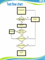
LEVEL 1-1 Notebook System Level 1 Training Material Statement of Confidentiality All recipients of this document must treat this training material as ASUS confidential and must not disclose it to any party other than the recipients’ employees on a need to know basis, or other individuals authorized under a written Confidential Disclosure Agreement signed by ASUS and the recipient. Ver. 4.0 2 Overview Chapter 1 Chapter 2 Chapter 3 Chapter 4 Chapter 5 Chapter 6 Chapter 7 Chapter 8 Testing/ Repair Flow Chart Customer Induced Damage (CID) Criteria NB Test Tools Visual Inspection Plug Fixture Updating BIOS Windows Testing Program Seagate HDD Test Program 3 Chapter 1 Testing/ Repair flow chart 4 Test flow chart Check Model Name FAIL Visual Inspection L2 Repair OK Plug Fixture Update BIOS NO BIOS Is The Newest Version? Yes FAIL DOS Function Test OK FAIL OS Function Test OK Key Out 5 Repair Flow Chart Receive Unpack Key In YES Out of Warranty Confirm with the Customer to repair NO YES L1 Key In Repair NO Fail Final Test Key Out Pack Ship 6 Chapter 2 Customer Induced Damage (CID) Criteria 7 CID&OOW Service Process Basic Flow Chart 8 CID for Hinge Problem Flow Chart The flow chart is for hinge problem which is in warranty. Hinge Problem Obvious Scratch & Broken on surface CID case No obvious scratch & broken on surface In warranty 9 Surface – Painting Peel Off 1 2 3 Damage Painting peel off [Figure1-5] 4 Comments LCD bezel or top case worn or painting peel off LCD cover or bottom case worn or painting peel off 5 Repair Way Exchange Parts In Warranty Out of Warranty Exchange or thicken the rubber - Free Charge - Exchange related parts Charge Charge - Exchange related parts Charge Charge 10 Surface - Broken 7 6 Damage Broken [Figure 6-14] 10 9 8 Comments Not caused by hit or droped Caused by hit or dropped or customer induced Repair Way Exchange Parts In Warranty Out of Warranty TBD - - - Exchange related parts - Charge Charge 11 Surface - Broken 11 12 13 14 12 Keyboard 15 Damage Repair Way Exchange Parts In Warranty Out of Warranty Keycap drop off Reinstall (If user preserves the keycap) - Free Free Keycap drop off - Charge Charge Comments Keycap drop off [Figure 15] Exchange the keyboard 13 Keyboard – Oxidation 16 Damage Keyboard Oxidation [Figure 16-17] 17 Comments Liquid soak into the keyboard and the top case. Repair Way Exchange Parts In Warranty Out of Warranty - Exchange the parts which was soaked by the liquid Charge Charge 14 Keyboard - Broken 18 Damage KeycapTwist [Figure 18-20] 19 20 Repair Way Exchange Parts In Warranty Out of Warranty Keycap twisted heated by the outside - Exchange the keyboard Charge Charge Keycap twisted by other reasons TBD - - - Comments 15 Keyboard / Touch Pad Abraded 21 22 23 Damage Keyboard or Touch Pad abraded [Figure 21-24] 24 Repair Way Exchange Parts In Warranty Out of Warranty Keyboard or Touch Pad was polished by the abrasion. - Exchange the keyboard or Touch Pad Charge Charge The sign on the keyboard or Touch Pad was drop off - Exchange the keyboard or Touch Pad Charge Charge Comments 16 Adapter– Surface Damaged 26 25 Damage Adapter surface damaged [Figure 25-26] Comments Adapter surface has water mark or melted or broken. Repair Way Exchange Parts In Warranty Out of Warranty - Exchange the adapter Charge Charge 17 Adapter – Cable Damaged 27 28 29 Damage Adapter Cable damaged [Figure 27-30] 30 Comments Cable broken and the plastic outside abraded Repair Way Exchange Parts In Warranty Out of Warranty - Exchange the adapter Charge Charge 18 Adapter – Label Damaged Label Damaged 31 Damage Comments Repair Way Exchange Parts In Warranty Out of Warranty Adapter label damaged [Figure 31] Label removed, scribbled or damaged seriously - Exchange the adapter Charge Charge 19 Mouse – Surface Damaged Surface damaged 32 Damage Comments Repair Way Exchange Parts In Warranty Out of Warranty Surface Damaged [Figure 32] The surface of the mouse split or damaged. - Exchange the mouse Charge Charge 20 Mouse – Cable damaged Cable twisted Wire broken 34 33 Damage Cable Damaged [Figure 33-34] Comments Cable twisted or wire broken Repair Way Exchange Parts In Warranty Out of Warranty - Exchange the mouse Charge Charge 21 Mouse – Label Damaged Label tear up by customer Label damaged and disassembled 35 Damage Label Damaged [Figure 35-36] Comments Label tear up by customer or disassembled after damaged 36 Repair Way Exchange Parts In Warranty Out of Warranty - Exchange the mouse Charge Charge 22 ODD – Mechanical Damaged 37 Damage Mechanical Damaged [Figure 37] Comments The hook broken, damaged or missed so that the ODD couldn’t read the disk. Repair Way Exchange Parts In Warranty Out of Warranty - Exchange the ODD Charge Charge 23 ODD – Mechanical Damaged ODD tray out of shape 38 ODD bracket broken Damage Mechanical Damaged [Figure 38-40] 39 Comments Includes: ODD bracket broken, ODD tray out of shape, data cable damaged, etc. 40 Repair Way Exchange Parts In Warranty Out of Warranty - Exchange the ODD Charge Charge 24 ODD Separate from the main machine and damage 41 Damage Comments Repair Way Exchange Parts In Warranty Out of Warranty Separate from the main machine [Figure 41] ODD separates from the main machine, data cable damaged - Exchange the ODD Charge Charge 25 LCD 42 43 Damage Comments Repair Way Charge LCD Broken [Figure 42-43] Panel crack and mural are considered caused by drop, press or misuse Replace the panel Yes 26 Machine Oxidation 44 Damage Liquid inside [Figure 44-45] 45 Comments It may be caused by misuse, ex: (a) Customer try to self-repair and use wrong way to clean to get the oxygenation. (b) 潑Splashed by liquid. Repair Way Check other parts and complete function first. Replace the damage parts Charge Yes 27 Machine Burned 46 47 Damage Comments Repair Way Charge NB Burned [Figure 46-47] Require to check the cause of such case carefully and seriously. If unable to judge the endures responsibility, please feedback to ASUS HQ. Replace the hole NB TBD 28 Chapter 3 NB Test Tools 29 ASUS NB Test Tools 30 ASUS NB Test Tools TOOLING BAG :16-000500007 31 Chapter 4 Visual Inspection 32 Visual Inspection Manner 1.1 Top Left 1.2 Right Left Right Bottom 1.Method and sequence for appearance inspection (1)Take down notes while reading: While inspecting, the operator’s focus need to follow by their hand. 33 Back Cover & Shake LCD 2.1 1.Check if the scratch, stain, paint, bright line of LCD cover are under inspection spec. 2.Tear LCD back cover Mylar. 2.2 1.Shake LCD module 3 times to check if hinges have some noise. 34 Check Bottom Case 3.1 3.2 1.Checking if the gap in the bottom case is under spec. 2.Check bottom case appearance that scratch, stain, print, color different, spray paint defector others appearance need to tally with inspection standard. 3.Check battery latch function well. 4.Check hole of speaker and DDR door no foreign objects. 5.Check the top case Mylar and battery Mylar are on NB, can‘t permit they are oblique or loss. 6.Check business card folder is stick on bottom case(for ASUS A3 series) 7.Check if scratch, stain, print, bright line of bottom case are under inspection spec. 35 Check Border Area 4.1 1.Check if the scratch, stain, paint, bright line of front side are under inspection spec. 2.Don’t tear bottom case IR lens Mylar. 4.2 1.Check if the scratch, stain, print, bright line of right side are under inspection spec. 4.3 1.Check if the scratch, stain, paint, bright line of rear side are under inspection spec. 2.Tear LCD back cover Mylar. 36 Check Inside Cover 5.1 5.2 1.Check if the scratch, stain, paint, bright line of left side under inspection spec. 2.Checking if there is any foreign object inside each jack of NB left side. 37 Check Gap & Device 6.1 6.2 1.Checking if the gap between LCD module and top case is under spec. 2.Checking if the scratch or pant off on the NB front side is under spec. 3.Checking if there is any foreign object inside each jack of NB left side. 38 Check LCD Surface & Rubber 7.1 1.Confirm if there is scratch on the LCD panel. 2.Checking the gap between LCD panel and LCD bezel is under spec. 3.Confirm if LCD panel is glare. 7.2 1.Confirm if there are 4 Mylar & 4 rubbers on the LCD bezel. 2.Check printing logo on LCD bezel. 39 Check PCMCIA & Top Case 8.1 1.Check if the PCMCIA push button function well. 8.2 1.Checking if there are Windows, Intel inside label, ATI label, CSR label, TNT label, Dolby label, Spec label, Promotion label had stuck on the top case. 40 Check Function Button 9.1 Important 1.Checking if the power button and fast key works smoothly. Checking if the gap, scratch, painting off, color difference or others surface defect of button are under standard. 41 Check Keyboard Important 10.1 10.2 Important Important 1.Checking if the K/B right side cannot saw VAG thermal module. 2.Make sure K/B and K/B cover wedge in top case and GAP under spec. 3.Use the palm of both hands to hit lightly K/B and make sure key of K/B have not floating, missing, noise and moving. 42 Check Bottom Case & Charge Pin 11.1 1.Checking if the gap, scratch, stain, painting off, color difference or others surface defect of bottom case are under standard. 2.Checking if the battery can slide smoothly and functioning. 11.2 1.Checking the gap between hinge covers and top case are under spec. 2.Checking if the scratch or pant off on the NB back side is under spec. 3.Checking if there is any foreign object inside each jack of NB right side. 4.Checking if there are 2 screws Mylar in the bottom case. 43 Check Battery & Warranty Label 12.1 For ASUS For HITACHI(OEM) Label cannot stuck over frame. 12.2 Check machine model number Name EX:W5AE 44 Check All Label & Cotton Paper 13.1 1.Confirm that number of 90 S/N pasted on machine is the same with on traveling card on bottom case. 2.Take the label-checking Mask putting on bottom case. 13.2 Put a anti-dust on the keyboard. 45 Chapter 5 Plug Fixture 46 Plug Fixture 1 2 1. Connect LAN Loop Back Plug 2. Put Test CD into ODD and reboot to run ASUS NB pretest programs 47 Plug Fixture 3 4 3. Connect USB port plug. 4. Connect MS PRO card plug. 48 Chapter 6 Updating BIOS Flashing BIOS introduction Preparation Flashing BIOS in Operating System Flashing BIOS in DOS mode Flashing BIOS in BIOS setup utility Jig Board 49 Flashing BIOS Introduction Updating BIOS could be the first option for the troubleshooting of the Notebook PC because the new BIOS revision will solve some problems. (Read the BIOS release information provided on the download site before using.) Four ways to flashing BIOS: Software: 1. Win flash in Operating System 2. A flash in NBDOS 3. Easy Flash in BIOS SETUP UTILITY Hardware: 4. Jig Board3 Warning: Careless updating can result in your Notebook PC having more problems. 50 Preparation Before starting flashing BIOS, please plug in the adapter so as to avoid the power off in the flashing process, which will lead to the BIOS flashing failure. 51 Flashing BIOS in Operating System 52 Precondition Two preconditions mentioned before starting to update the BIOS in OS: 1. Download the exact BIOS files from the ASUS website • Before starting updating BIOS in OS, please verify the NB model then download the corresponded BIOS files from the ASUS website. • The BIOS file can be found in the website as below: http://www.asus.com 2. Please ensure the updating program ‘Winflash Utility’ has been installed in your NB before you start BIOS updating. The program can be installed from the Driver & Utility CD. 53 Flashing BIOS in Operating System 1. Open the program “Winflash” Click Start\All Programs\ASUS Utility\Winflash\Winflash V2.25 1 54 Flashing BIOS in Operating System 2. Select and open the BIOS files downloaded from the website. 2 55 Flashing BIOS in Operating System 3. Confirm the BIOS information is correct and press “Flash” button to start. 3 56 Flashing BIOS in Operating System 4. The system would shut down automatically and reboot again to enter the easy flash interface to start flashing the BIOS. 4 57 Flashing BIOS in Operating System 5. Erasing BIOS 5 58 Flashing BIOS in Operating System 6. Flashing BIOS 6 59 Flashing BIOS in Operating System 7. Verify BIOS. After flash successfully, the system would shut down automatically. 7 60 Flashing BIOS in Operating System 8. Please restart and enter the BIOS setup interface to Load User Defaults. 8 9 61 Warning • The model is not matching • The version is not the latest or older than the BIOS In these two situations, the BIOS could not be updated. The message would show and the “Flash” button would not be activable. 62 Downgrade BIOS Description: With the new version of the BIOS, some functions would be disabled. In this case, downgrade BIOS would be adapted. For the WINFLASH grogram could only upgrade BIOS, one command should be run before the downgrade. 63 Downgrade BIOS 1. Enter into the DOS mode in OS 1 64 Downgrade BIOS 2. Run “winflash /nodate” in the DOS mode (The path is as below) 2 3 65 Downgrade BIOS 3. Choose the BIOS image file. 4 66 Downgrade BIOS 4. Start to Downgrade. 5 67 Downgrade BIOS 5. The system would shut down automatically and reboot again to enter the easy flash interface to start flash the BIOS. 6 68 Downgrade BIOS 6. Erasing BIOS 7 69 Downgrade BIOS 7. Flashing BIOS 8 70 Downgrade BIOS 8. Verify BIOS. After flash successfully, the system would shut down automatically. 9 71 Downgrade BIOS 9. Please restart and enter the BIOS setup interface to Load User Defaults. 10 11 72 Flashing BIOS in NBDOS 73 Preparation Download the BIOS image files from the SIP website (As it mentioned in the flashing BIOS in OS) Prepare a USB DOS booting flash disk with the “AFLASH2.EXE” program and the BIOS image files in. 74 Flashing BIOS in NBDOS 1. Booting from the USB to enter into the NBDOS 1 75 Flashing BIOS in NBDOS 2. Select aflash2.exe to run updating BIOS grogram 2 76 Flashing BIOS in NBDOS 3. Select <2.update BIOS to new version> 3 77 Flashing BIOS in NBDOS 4. Input file name of new BIOS 4 78 Flashing BIOS in NBDOS 5. Confirm the new BIOS name and make sure to start flashing In this stage, please carefully check the model and version is correct then enter “Y” to continue, otherwise the system will flash a wrong BIOS which will cause the problem of no boot. 5 79 Flashing BIOS in NBDOS 6. Erasing BIOS 6 80 Flashing BIOS in NBDOS 7. Flashing BIOS 7 81 Flashing BIOS in NBDOS 8. Verify BIOS 8 82 Flashing BIOS in NBDOS 9. Complete Flashing and EXIT 9 83 Flashing BIOS in NBDOS 10. Restart the PC and enter into the BIOS SETUP UTILITY to check the BIOS info. 10 11 84 Flashing BIOS in BIOS SETUP UTILITY Description: For the computer with the Napa platform and the latter one, BIOS updating could be completed directly in the BIOS setup interface. 85 Flashing BIOS in BIOS SET UTILITY 1. Press F2 to enter the BIOS SETUP Interface to start the flashing. The procedure is as below: 1 86 Flashing BIOS in BIOS SET UTILITY 2. Start to Easy Flash 2 87 Flashing BIOS in BIOS SET UTILITY 3. Select the BIOS file path 3 88 Flashing BIOS in BIOS SET UTILITY 3. Confirm to update BIOS 4 89 Flashing BIOS in BIOS SET UTILITY 4. Erasing BIOS 5 90 Flashing BIOS in BIOS SET UTILITY 5. Flashing BIOS 6 91 Flashing BIOS in BIOS SET UTILITY 6. Verify BIOS 7 92 Flashing BIOS in BIOS SET UTILITY 7. Restart the PC and enter into the BIOS SETUP UTILITY to check the BIOS info. 8 9 93 Flashing BIOS by Jig Board3 Description: This is a tool for flashing BIOS. The other three ways introduced before is for the software. In the case of failure flashing BIOS by software, which would cause no boot, the BIOS could be flashed by another tool – JIG BOARD3. 94 Overview 95 Overview CN1 USB connector. CN2 GND connector. BTN1 Main power button. BTN2 RESET button BTN3 Start button. BTN4 Function button. LED1 Software On Power LED. LED2 Good, Fail, Busy, PWR LED LED3 Function indicator LED LED4 Message ID LED indicator. SW1 Function Switch U1 SPI Flash IC J301 UP connect connector J302 Down connect connector 96 Notebook Supported The JIG Board3 ONLY supports the notebook PC whose EC chip is ITE. (This list didn’t included all the unit but an example.) A A3AC A3FC A3FP A3H A3HF A6F A6RP A6HF A7C A7CD A7J A7F A7P A7S A8E A8S A8SC A9RP C C90S F F3SA F3SC F3SV F3SE F9DC F9E F9S F2F F2HF F2J F2JE F3F F3H F3P F3JA F3JC F3JP F3JR F3JM F3JV F3M F3T F3TC F3U F5R F5M F9F F9J G R G1S G2S G2P R1E R1F T T12EG T12FG T12FF T12FH T12FV T12H T12J T12J3 T12JG T12RG T12RV TRSA T11F T11J T11JA T11JB T11JL T12RV T12MG T12MV T12UV T13FG T13FV T13MV T19F T19H T19R V VX2S V2JE W W2S W7S W7E W1JB U U1F X X51R Z Z37E Z84J Z96S Z62F Z62FP Z62FM Z62J Z62JM Z84F Z84FM Z91FR Z94RP Z96F Z96FM Z96H Z96HM Z96J Z96JM Z96JP Z96JS 97 Flashing BIOS with JIG Board3 Update BIOS binary file to JIG3 1. Connect USB cable from CN1 to your PC’s USB connector. Set SW1 to 0000. Then press POWER button to turn on power. (Power LED will turn on) Please also check LED4 will show 00. SW1 1 CN1 98 Flashing BIOS with JIG Board3 2. Run ASUS Winflash Utility. Check the USB Device ‘ASUS JIG3’ is plug in and ready to flash. If all is ready, press the button to load and press “Autoburn” to burn the BIOS file. 2 3 Check Point 99 Flashing BIOS with JIG Board3 3. When the burning is done, press POWER button again to turn off the main power. 4 100 Flashing BIOS with JIG Board3 Upload the target board’s BIOS ROM 1. Remove the battery and the power supply of the target board. 1 101 Flashing BIOS with JIG Board3 2. Connect the USB cable from CN1 to your PC’s USB connector. ( Make sure here the PC is not the target board while is another PC to support the power to the JIG board3.) CN1 2 102 Flashing BIOS with JIG Board3 3. Connect FPC cable from J301(UP connect) or J302(Down connect) to your target board’s keyboard connector, choosing J301 or J302 by target board connector type. Make sure JIG3 J30x’s Pin1 is connected to keyboard connector’s Pin1 of the target board. J301 J302 Pin1 3 103 Flashing BIOS with JIG Board3 4. Use a USB cable to make common ground between JIG3 and target board. Connect JIG3 CN2 to the USB port of target board and make sure all power sources was removed from target board. 4 104 Flashing BIOS with JIG Board3 5. Set DIP to “1000” and turn on JIG3 Power.LED4 will show 01. 5 105 Flashing BIOS with JIG Board3 6. Make sure JIG3 is on and the finally connection is the power adapter into the target board. Don’t power on the target board before JIG3 POWER ON. 6 106 Flashing BIOS with JIG Board3 7. Wait until busy LED off and press Start button. Update will be start. Wait for a few second, LED4 show “88” and Good LED in LED2 is on. Remove power supply from target board. Turn off JIG3 power. 7 107 Message ID List Message Process 55 KBS test fail 10 20~2F Flash erase Flash Check Flash Programming Flash Verify Flash Error Bios file error Flash successfully Bootloader Error 30~3F 40~4F CC DD 88 4F Note The scenario will influence by the following conditions: The JIG Board crisis recovery data structure did not match the target keyboard connector define. The target system has other power sources before JIG3 turn on. Could not detect Flash Need update JIG3 Firmware. 108 SPI Extend Card Overview Description: This tool can support JIG Board3 to flash BIOS on Compal machines. 109 SPI Extend Card Overview The JIG Board3 with SPI Extend Card ONLY supports the notebook PC whose EC chip is ENE. (This list didn’t included all the unit but an example.) K series K43BY K53BY K53U K43U K73BY K43TA K93SV K73TA 110 Flashing BIOS with JIG3 and SPI Card Update BIOS binary file to Target via SPI extend card 1. Remove all power source (include battery and power supply) from target board. Plug in SPI extend card to JIG3 extend port (CON301). Extend card doesn’t support hotplug. 1 111 Flashing BIOS with JIG3 and SPI Card 2. Connect the USB cable from CN1 to your PC’s USB connector. Connect FPC cable from SPI extend card to your target board’s keyboard connector, make sure SPI extend card connect Pin1 is connected to target board’s keyboard connector Pin1. 2 112 Flashing BIOS with JIG3 and SPI Card 3. Use a USB cable connect GND between JIG3 CN2 and target board USB port. Make sure all power sources was removed from target board. 3 113 Flashing BIOS with JIG3 and SPI Card 4. Set SW1 to 0000. 5. Press POWER button to turn on the power, power led will turn on. Check LED4 will show 00. 4 114 Flashing BIOS with JIG3 and SPI Card 6. Run ASUS_WinFlash utility. The logo will show the project name that has to connect target board and SPI extend card. If you didn’t connect it yet, please exit the ASUS_WinFlash and go back to the step 1. Check it 115 Flashing BIOS with JIG3 and SPI Card 7. Check the USB Device “ASUS JIG3” is Plug-in and Flash of SPI extend card. 5 116 Flashing BIOS with JIG3 and SPI Card 6 117 Chapter 7 Windows Testing Program 118 Download WTP Program Step 1: Login RMA Support Web and click Test Program. 119 Download WTP Program Step 2: Follow the path and download WTP. Scope:Models: EPC/NB/E-Pad Applied OS: Windows XP/Vista/Win7 120 Download WTP Program Step 3: Update WTP BIOS TXT: The new Bios will be release every week. Please download file and overwrite WTP BIOS_TXT to WTP \ bin \ conf \. 121 Download WTP Program Step 4: New Model WTP Setup for Update: The New Model WTP Setup-for update will be release every week. It contains the WTP BIOS_TXT and new model profile. Please download file and overwrite New Model WTP Setup-for update to WTP \ bin \. 122 Set for WTP Program Step 1: BIOS Setup: Press F2 to the BIOS when unit booting on, load Setup Defaults and setup System Time/Date. Then enable all devices. Finally Save Changes and Exit. (System will reboot) 123 Set for WTP Program Step 2: Product select : Since the program supports multiple different products. Run “ConfigModel.exe” before “DiagEG.exe”. 124 WTP Main Menu Step 1: Run DiagEG.exe on desktop 125 WTP Test Flow This is a test process sample. Test items need in accordance with the actual function. Start Please scan S/N Background Start Please scan S/N again WIFI Test Please select your stage LAN Test Please input your ID USB and Card Reader Test Battery State Test Memory Check Internal Speaker and MIC Test CPU Check External Speaker and MIC Test Webcam Auto Test BIOS Version Check Bluetooth Test Full Screen Pattern Test Fan Test Keyboard Test VGA Info Test Touchpad and Keyboard Test LED Check Webcam Test Instant Key Test Fail Item Retest Exit Report END 126 WTP Main Interface The next page will show each item. 127 WTP Main Interface Introduction for each item. 01. Print Result: Print out test result. 02. Run All: Run all the tests under Function tests. 03. Aging: Run aging programs. 04. Test Menu: Function test menu and Advance test menu. 05. Function Test: basic tests are accessible here and may be executed separately. 06. Advance Test: for specific purposes are available here. 07. WTP Version: show WTP version. 08. System Information: Spec. and status are listed here for reference. 09. Log folder: report save path. Select up-left window and save button to change path. 10. Refresh: for an immediate update system information. 128 WTP Test Interface The next page will show each item. 129 WTP Test Interface Introduction for each item. 01. Test Result. 02. Test Time. 03. Error at where. 04. Error code. 05. Interactive Test state. 06. Background Test state. 07. Exit test program. 08. Current running inter active test. 09. Test state. 10. Test results are listed here: a. Function tests determined by program and executed in the background automatically. b. Function tests require human judgment and executed manually. 130 WTP Test Interface The program runs two kinds of tests at the same time. Some of the testing program can automatically detect what we call background test. Test items will be in accordance with the specifications of models change. Single Test Basic tests are accessible here and may be executed separately All Test You can select “Run All” button to test all function. 131 Scan/Stage Scan or key in the S/N, select the repair stage, type in the employee ID. Scan the S/N of the product (15-digit maximum) Scan the S/N of the product again. Type in the your employee ID. Select the stage and press OK. 132 Battery Test Please follow the instructions to plug or plug off adapter in 10 seconds. 133 Internal Speaker and Microphone Test 1. You can press F10 to trigger a FAIL at any time. 2. Left channel test: Listen to the voice and press the number on the keyboard. 3. Right channel test: Listen to the voice and press the number on the keyboard. 134 Internal Speaker and Media Test 4. Microphone Test: Please speak into microphone and press ok button to recording. Please listen to speaker and press ok button start playing. 5. Manually press PASS, FAIL, and RETRY depending on the result. If select “FAIL”, you must confirm again to avoid a wrong choice. 6. Media play test: You can test internal speaker noise by Media play test. 135 External Audio Test 136 BIOS Version Check You can compare the older BIOS version and new version in screen. The BIOS check list will release every week on SIP. Please overwrite BIOS_TXT to WTP \ bin \ conf \ or overwrite New Model WTP Setup-for update to WTP \ bin \. 137 LCD Panel Test Screen displays black, white and bands of color for examining the quality of LCD panel. Please press space key for next test. Manually press PASS, FAIL, and RETRY depending on the result. If select “FAIL”, you must confirm again to avoid a wrong choice. 138 Keyboard Test Please select the language. Click all the keys on the keyboard. For [Fn] key on the left, press [Fn] and [Del]. For [Fn] key on the right, press [Fn] and [Ins]. If no key is pressed in 20 seconds, the test fails. 139 Touchpad Test Move the cursor to the gray blocks. Try to test in different directions if by finger. Scroll up and down with two fingers. Two fingers to actually touch the Touchpad. Scroll up and down in the middle. 140 LED Test Press “Next” button and watch the LED make sure they blink. If the LED does not light up, press fail and may repeat the test again to ensure the LED actually failed. Once the LED’s entire are checked, press PASS button to end the test. 141 Webcam Test Once the image shows up, please wait 5 seconds to end the test. If single test, please press space key to end the test. Manually press PASS, FAIL, and RETRY depending on the result. If select “FAIL”, you must confirm again to avoid a wrong choice. 142 Instant Key Test Press the instant keys and make sure the color turns from black to blue. Once all the keys are checked, press PASS to end the test. 143 Instant Key Test Press the instant keys again to turn touch pad on. 144 ODD Test ODD Eject test: Need have ODD and only test eject function. 145 LAN Test Make sure the machine is (wired) connected directly to the test AP or under the same network domain with the test AP. 146 WIFI Test Make sure to setup the AP with SSID as “tc_test” without encryption before performing the test. 147 USB/ Card Reader Test To test the USB ports and card reader, make sure all the USB ports are occupied with USB memory drives (USB Flash, USB mouse…etc). Also, make sure a memory card is placed in the card reader. 148 Bluetooth Test Bluetooth start searching for other Bluetooth devices. Make sure there are at least one Bluetooth device around is active. 149 Fail Items Retry If “Run All” has tested fail item, when finish all test, it will show below screen. Please select “Retry” to test fail item again, or select “Cancel” to ignore. 150 Test Report If all tests pass, it will show below picture. Press “Exit” button end of the test program. 151 Test Report Test result is listed here with PASS or FAIL recorded. Press “Print” to print out the result or “Close” to close the window. If you “Close”, report will auto save. Please refer setup (10.2 Setting report save path). Open file to check test result. (Test Report\Detailed report\SN.pdf). 152 Advance Test We provide an interface that can link to your favorite programs. Please use the copyrighted program. We have provided a number of programs available for your use. The following describes how to add and delete programs. 153 Aging Test Aging test provides the function to set advanced test time. When the test is completed the voice and message will appear to remind the user. 154 Aging Test Aging Screen: Run Aging test and set the test time, and then start the test. Press the “RUN” button to test, more detail please refer AsAging_SOP. 155 Chapter 8 Seagate HDD Test Program 156 Seagate HDD Test Program Step 1: Download the Program from“Key Parts Test" on RMA Support Website. 1 157 Seagate HDD Test Program Step 2: Check the HDD vender and SOP. 2 158 Seagate HDD Test Program Step 3: Prepare a bootable USB disk (pen drive) ,extract STI Express Tool V13.RAR file and copy STI Express Tool V13 file to bootable USB disk 3 159 Seagate HDD Test Program Step 4: Please insert bootable USB disk and boot from this disk. 4 160 Seagate HDD Test Program Step 5: Enter STI Express Tool V13 data folder, and then run FDAUTO.BAT 5 161 Seagate HDD Test Program Step 6: There are four options 6 1. Short Read test : Random read & Test time is in 30 mins; 2. Short Write test : Clear MBR sector to avoid Recovery system fail. If perform this test, we must obtain the consent of customers. 3. Long Read test : Sequential read at all sectors. 4. Long Write test : All data on HDD will be erased, this test can repair the logical bad sectors on HDD, but all data on HDD will be permanently erased. If perform this test, we must obtain the consent of customers. 162 Seagate HDD Test Program Step 7: Select Long Read Test . Waiting for the test completed, the test program will prompt “Press any key to continue”. 7 163 Seagate HDD Test Program Step 8: Press the key, the result as follows 8 164