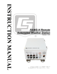
1
INSTRUCTION MANUAL HMP155A Temperature and Relative Humidity Probe Revision: 10/14 C o p y r i g h t © 1 9 9 0 - 2 0 1 4 C a m p b e l l S c i e n t i f i c , I n c . Limited Warranty “Products manufactured by CSI are warranted by CSI to be free from defects in materials and workmanship under normal use and service for twelve months from the date of shipment unless otherwise specified in the corresponding product manual. (Product manuals are available for review online at www.campbellsci.com.) Products not manufactured by CSI, but that are resold by CSI, are warranted only to the limits extended by the original manufacturer. Batteries, fine-wire thermocouples, desiccant, and other consumables have no warranty. CSI’s obligation under this warranty is limited to repairing or replacing (at CSI’s option) defective Products, which shall be the sole and exclusive remedy under this warranty. The Customer assumes all costs of removing, reinstalling, and shipping defective Products to CSI. CSI will return such Products by surface carrier prepaid within the continental United States of America. To all other locations, CSI will return such Products best way CIP (port of entry) per Incoterms ® 2010. This warranty shall not apply to any Products which have been subjected to modification, misuse, neglect, improper service, accidents of nature, or shipping damage. This warranty is in lieu of all other warranties, expressed or implied. The warranty for installation services performed by CSI such as programming to customer specifications, electrical connections to Products manufactured by CSI, and Product specific training, is part of CSI's product warranty. CSI EXPRESSLY DISCLAIMS AND EXCLUDES ANY IMPLIED WARRANTIES OF MERCHANTABILITY OR FITNESS FOR A PARTICULAR PURPOSE. CSI hereby disclaims, to the fullest extent allowed by applicable law, any and all warranties and conditions with respect to the Products, whether express, implied or statutory, other than those expressly provided herein.” Assistance Products may not be returned without prior authorization. The following contact information is for US and international customers residing in countries served by Campbell Scientific, Inc. directly. Affiliate companies handle repairs for customers within their territories. Please visit www.campbellsci.com to determine which Campbell Scientific company serves your country. To obtain a Returned Materials Authorization (RMA), contact CAMPBELL SCIENTIFIC, INC., phone (435) 227-9000. After an application engineer determines the nature of the problem, an RMA number will be issued. Please write this number clearly on the outside of the shipping container. Campbell Scientific’s shipping address is: CAMPBELL SCIENTIFIC, INC. RMA#_____ 815 West 1800 North Logan, Utah 84321-1784 For all returns, the customer must fill out a “Statement of Product Cleanliness and Decontamination” form and comply with the requirements specified in it. The form is available from our web site at www.campbellsci.com/repair. A completed form must be either emailed to [email protected] or faxed to (435) 227-9106. Campbell Scientific is unable to process any returns until we receive this form. If the form is not received within three days of product receipt or is incomplete, the product will be returned to the customer at the customer’s expense. Campbell Scientific reserves the right to refuse service on products that were exposed to contaminants that may cause health or safety concerns for our employees. Precautions DANGER — MANY HAZARDS ARE ASSOCIATED WITH INSTALLING, USING, MAINTAINING, AND WORKING ON OR AROUND TRIPODS, TOWERS, AND ANY ATTACHMENTS TO TRIPODS AND TOWERS SUCH AS SENSORS, CROSSARMS, ENCLOSURES, ANTENNAS, ETC. FAILURE TO PROPERLY AND COMPLETELY ASSEMBLE, INSTALL, OPERATE, USE, AND MAINTAIN TRIPODS, TOWERS, AND ATTACHMENTS, AND FAILURE TO HEED WARNINGS, INCREASES THE RISK OF DEATH, ACCIDENT, SERIOUS INJURY, PROPERTY DAMAGE, AND PRODUCT FAILURE. TAKE ALL REASONABLE PRECAUTIONS TO AVOID THESE HAZARDS. CHECK WITH YOUR ORGANIZATION'S SAFETY COORDINATOR (OR POLICY) FOR PROCEDURES AND REQUIRED PROTECTIVE EQUIPMENT PRIOR TO PERFORMING ANY WORK. Use tripods, towers, and attachments to tripods and towers only for purposes for which they are designed. Do not exceed design limits. Be familiar and comply with all instructions provided in product manuals. Manuals are available at www.campbellsci.com or by telephoning (435) 227-9000 (USA). You are responsible for conformance with governing codes and regulations, including safety regulations, and the integrity and location of structures or land to which towers, tripods, and any attachments are attached. Installation sites should be evaluated and approved by a qualified engineer. If questions or concerns arise regarding installation, use, or maintenance of tripods, towers, attachments, or electrical connections, consult with a licensed and qualified engineer or electrician. General • Prior to performing site or installation work, obtain required approvals and permits. Comply with all governing structure-height regulations, such as those of the FAA in the USA. • Use only qualified personnel for installation, use, and maintenance of tripods and towers, and any attachments to tripods and towers. The use of licensed and qualified contractors is highly recommended. • Read all applicable instructions carefully and understand procedures thoroughly before beginning work. • Wear a hardhat and eye protection, and take other appropriate safety precautions while working on or around tripods and towers. • Do not climb tripods or towers at any time, and prohibit climbing by other persons. Take reasonable precautions to secure tripod and tower sites from trespassers. • Use only manufacturer recommended parts, materials, and tools. Utility and Electrical • You can be killed or sustain serious bodily injury if the tripod, tower, or attachments you are installing, constructing, using, or maintaining, or a tool, stake, or anchor, come in contact with overhead or underground utility lines. • Maintain a distance of at least one-and-one-half times structure height, 20 feet, or the distance required by applicable law, whichever is greater, between overhead utility lines and the structure (tripod, tower, attachments, or tools). • Prior to performing site or installation work, inform all utility companies and have all underground utilities marked. • Comply with all electrical codes. Electrical equipment and related grounding devices should be installed by a licensed and qualified electrician. Elevated Work and Weather • Exercise extreme caution when performing elevated work. • Use appropriate equipment and safety practices. • During installation and maintenance, keep tower and tripod sites clear of un-trained or nonessential personnel. Take precautions to prevent elevated tools and objects from dropping. • Do not perform any work in inclement weather, including wind, rain, snow, lightning, etc. Maintenance • Periodically (at least yearly) check for wear and damage, including corrosion, stress cracks, frayed cables, loose cable clamps, cable tightness, etc. and take necessary corrective actions. • Periodically (at least yearly) check electrical ground connections. WHILE EVERY ATTEMPT IS MADE TO EMBODY THE HIGHEST DEGREE OF SAFETY IN ALL CAMPBELL SCIENTIFIC PRODUCTS, THE CUSTOMER ASSUMES ALL RISK FROM ANY INJURY RESULTING FROM IMPROPER INSTALLATION, USE, OR MAINTENANCE OF TRIPODS, TOWERS, OR ATTACHMENTS TO TRIPODS AND TOWERS SUCH AS SENSORS, CROSSARMS, ENCLOSURES, ANTENNAS, ETC. Table of Contents PDF viewers: These page numbers refer to the printed version of this document. Use the PDF reader bookmarks tab for links to specific sections. 1. Introduction ................................................................. 1 2. Cautionary Statements ............................................... 1 3. Initial Inspection ......................................................... 1 3.1 Ships With............................................................................................ 2 4. Quickstart .................................................................... 2 4.1 4.2 Assembly and Mounting ...................................................................... 2 Use SCWin to Program Datalogger and Generate Wiring Diagram .... 5 5. Overview ...................................................................... 7 6. Specifications ............................................................. 8 6.1 6.2 Temperature Sensor ........................................................................... 10 Relative Humidity Sensor .................................................................. 11 7. Installation ................................................................. 11 7.1 7.2 7.3 7.4 7.5 Siting .................................................................................................. 11 Wiring ................................................................................................ 11 Datalogger Programming ................................................................... 13 Long Lead Lengths ............................................................................ 13 Absolute Humidity ............................................................................. 14 8. Sensor Maintenance ................................................. 15 8.1 Periodic Maintenance ......................................................................... 15 8.1.1 Cleaning ...................................................................................... 15 8.1.2 Changing the Probe Filter ........................................................... 15 9. Troubleshooting........................................................ 16 10. References ................................................................ 17 Appendices A. Importing Short Cut Code ...................................... A-1 A.1 Importing Short Cut Code into a Program Editor ........................... A-1 B. Example Programs ................................................. B-1 B.1 Single-Ended Voltage Measurement Example................................. B-1 i Table of Contents B.2 B.3 Differential Measurement Example ................................................ B-2 Mean Vapor Pressure Example ....................................................... B-3 C. Interfacing with HMP155A RS-485 Output ............ C-1 C.1 C.2 RS-485 Interface Options ................................................................ C-1 SDM-SIO1 Serial I/O Module Interface Option ............................. C-1 C.2.1 Program Example for SDM-SIO1 Module............................... C-1 C.3 MD485 Multidrop Interface Option ................................................ C-4 C.3.1 MD485 Multidrop Interface Configuration .............................. C-6 C.3.2 CR1000 Example Program for use with MD485 ..................... C-7 Figures 4-1. 4-2. 4-3. 4-4. 6-1. 6-2. 8-1. HMP155A in shipping box.................................................................. 2 Cable routed through the connector cover ........................................... 3 Cable connected to the sensor ............................................................. 3 HMP155A with connector cover in place and without protective cap .................................................................................................... 3 HMP155A and 14-plate radiation shield on a tripod mast .................. 4 HMP155A and 14-plate radiation shield on a CM200-series crossarm ........................................................................................... 4 Probe dimensions ................................................................................ 9 Wiring of HMP155A 8-pin connector ................................................. 9 Changing the filter ............................................................................. 15 5-1. 7-1. 7-2. 7-3. 7-4. 8-1. B-1. B-2. B-3. Recommended Lead Lengths .............................................................. 8 Connections for Single-Ended Measurements .................................. 12 Connections for Differential Measurements...................................... 12 Parameters for Temperature .............................................................. 13 Parameters for Relative Humidity ..................................................... 13 Chemical Tolerances of HMP155A .................................................. 16 Wiring for Single-ended Measurement Examples ........................... B-1 Wiring for Differential Measurement Examples ............................. B-2 Wiring for Vapor Pressure Examples .............................................. B-3 4-5. 4-6. Tables ii HMP155A Temperature and Relative Humidity Probe 1. Introduction The HMP155A probe monitors relative humidity (RH) for the range of 0 to 100% RH and temperature for the range of –80 to 60 °C. It can provide reliable measurements for a wide range of applications, as part of a weather station system or as a single instrument. All Campbell Scientific dataloggers are compatible. NOTE 2. 3. This manual provides information only for CRBasic dataloggers. It is also compatible with most of our retired Edlog dataloggers. For Edlog datalogger support, see an older manual at www.campbellsci.com/old-manuals or contact a Campbell Scientific application engineer for assistance. Cautionary Statements • READ AND UNDERSTAND the Precautions section at the front of this manual. • Care should be taken when opening the shipping package to not damage or cut the cable jacket. If damage to the cable is suspected, consult a Campbell Scientific application engineer. • Although the HMP155A is rugged, it should be handled as a precision scientific instrument. • Do not touch the sensor element. • The black outer jacket of the cable is Santoprene® rubber. This compound was chosen for its resistance to temperature extremes, moisture, and UV degradation. However, this jacket will support combustion in air. It is rated as slow burning when tested according to U.L. 94 H.B. and will pass FMVSS302. Local fire codes may preclude its use inside buildings. Initial Inspection • Upon receipt of the HMP155A, inspect the packaging and contents for damage. File damage claims with the shipping company. • The model number and cable length are printed on a label at the connection end of the cable. Check this information against the shipping documents to ensure the correct product and cable length are received. • Refer to the Ships With list to ensure that parts are included (see Section 3.1). 1 HMP155ATemperature and Relative Humidity Probe 3.1 Ships With The HMP155A ships with: (1) Adjustment Screwdriver from manufacturer (1) Calibration Sheet (1) Instruction Manual or ResourceDVD 4. Quickstart Review Section 7, Installation, for siting, wiring, and CRBasic programming information. 4.1 Assembly and Mounting Tools Required: • • • • 1/2 inch open end wrench small screw driver provided with datalogger UV resistant cable ties small pair of diagonal-cutting pliers To install the HMP155A, you will need the 41005-5 14-Plate Radiation Shield. The HMP155A is packaged with a white connector cover and a yellow sensor head protective cap. See FIGURE 4-1. Protective Cap Connector Cover FIGURE 4-1. HMP155A in shipping box 1. 2 Slide the white connector cover off the sensor head before removing the sensor from the box. HMP155A Temperature and Relative Humidity Probe 2. Squeeze the sides of the white connector cover and insert the cable’s connector through it (see FIGURE 4-2). Cable Connector Connector Cover FIGURE 4-2. Cable routed through the connector cover 3. Attach the cable to the mating connector on the bottom of the HMP155A (see FIGURE 4-3). FIGURE 4-3. Cable connected to the sensor 4. Slide the white connector cover over the connector and gently push it up as far as it will go. The white connector cover has built-in molded stops that will only allow it to slide up so far. See FIGURE 4-4. FIGURE 4-4. HMP155A with connector cover in place and without protective cap 5. Loosen the split-nut on the bottom plate of the 41005-5 14-plate radiation shield. 6. Remove the yellow protective cap on the HMP155A, and insert the sensor into the shield. 7. Tighten the hex plug such that it compresses against the body of the HMP155A to hold it inside the 41005-5 radiation shield. 8. If mounting the 41005-5 directly to a mast, place the 41005-5 U-bolt in the side holes and secure the 41005-5 to the mast by tightening the U-bolt nuts (FIGURE 4-5). 9. If using a CM200-series crossarm, mount the crossarm to the tripod or tower. Then place the 41005-5’s U-bolt in the bottom holes and secure the 41005-5 to the crossarm by tightening the U-bolt nuts (see FIGURE 4-6). 10. Route the cable to the datalogger, and secure the cable to the mounting structure using cable ties. 3 HMP155ATemperature and Relative Humidity Probe 14-Plate Radiation Shield Split Nut U-bolt Connector Cover FIGURE 4-5. HMP155A and 14-plate radiation shield on a tripod mast CM200 Series Crossarm FIGURE 4-6. HMP155A and 14-plate radiation shield on a CM200-series crossarm 4 HMP155A Temperature and Relative Humidity Probe 4.2 Use SCWin to Program Datalogger and Generate Wiring Diagram Short Cut is an easy way to program your datalogger to measure the HMP155A and assign datalogger wiring terminals. The following procedure shows using Short Cut to program the HMP155A. 1. Install Short Cut by clicking on the install file icon. Get the install file from either www.campbellsci.com, the ResourceDVD, or find it in installations of LoggerNet, PC200W, PC400, or RTDAQ software. 2. The Short Cut installation should place a shortcut icon on the desktop of your computer. To open Short Cut, click on this icon. 3. When Short Cut opens, select New Program. 5 HMP155ATemperature and Relative Humidity Probe 4. Select Datalogger Model and Scan Interval (default of 5 seconds is OK for most applications). Click Next. 5. Under the Available Sensors and Devices list, select the Sensors | Meteorological | Relative Humidity & Temperature | HMP155 folder. Select HMP155 (constant power) or HMP155 (panel switched power) (shown). Click to move the selection to the Selected device window. The temperature defaults to degrees Celsius. This can be changed by clicking the Temperature box and selecting one of the other options. 6 HMP155A Temperature and Relative Humidity Probe 5. 6. After selecting the sensor, click at the left of the screen on Wiring Diagram to see how the sensor is to be wired to the datalogger. The wiring diagram can be printed out now or after more sensors are added. 7. Select any other sensors you have, then finish the remaining Short Cut steps to complete the program. The remaining steps are outlined in Short Cut Help, which is accessed by clicking on Help | Contents | Programming Steps. 8. If LoggerNet, PC400, RTDAQ, or PC200W is running on your PC, and the PC to datalogger connection is active, you can click Finish in Short Cut and you will be prompted to send the program just created to the datalogger. 9. If the sensor is connected to the datalogger, as shown in the wiring diagram in step 6, check the output of the sensor in the datalogger support software data display to make sure it is making reasonable measurements. Overview The HMP155A Temperature and Relative Humidity probe contains a platinum resistance temperature detector (PRT) and a Vaisala HUMICAP 180 capacitive relative humidity sensor. The HMP155A outputs a 0 to 1 Vdc signal for temperature and relative humidity that can be measured by all models of Campbell Scientific dataloggers with model HMP155ACBL1 cable. The HMP155A also has RS-485 outputs for temperature and relative humidity that can be interfaced to the CR6 datalogger with the HMP155ACBL2 cable. The RS-485 output can also be used with our CR800, CR850, CR1000, and CR3000 dataloggers, but they require both the HMP155ACBL2 cable and the SDM-SIO1 Serial I/O Module (Appendix C, Interfacing with HMP155A RS-485 Output). The RS-485 outputs has a higher current drain than that listed in the specifications. 7 HMP155ATemperature and Relative Humidity Probe The HMP155A can be powered continuously or the power may be switched to conserve battery life. The HMP155A consumes less than 3 milliamps current at 12 Vdc. Approximately 2 seconds is required for the sensor to warm up after power is switched on. At measurement rates slower than once per 5 seconds, the overall power consumption (datalogger and sensors) may be reduced by switching power to the HMP155A. Most current Campbell Scientific dataloggers have a built-in switched 12 Vdc that can be used to control power. The CR9000 and many Edlog dataloggers do not have a built-in switched and require the SW12 to switch power (see at www.campbellsci.com/old-manuals or contact a Campbell Scientific application engineer for more information). HMP155 sensors purchased directly from Vaisala with serial numbers < E4430001 require approximately 5 seconds warm up time. NOTE The -L option on the model HMP155A Temperature and Relative Humidity probe (HMP155A-L) indicates that the cable length is user specified. TABLE 5-1 gives the recommended lead length. Add 2 ft to the cable length if the enclosure is mounted to the leg base of a CM106B, CM110, CM115, or CM120 tripod. TABLE 5-1. Recommended Lead Lengths 2 m Height Atop a tripod or tower via a 2 ft crossarm Mast/Leg CM202 CM106B CM110 CM115 CM120 UT10 UT20 UT30 9 ft 11 ft 14 ft 14 ft 19 ft 24 ft 14 ft 24 ft 37 ft The probe’s cable can terminate in: • • 6. Pigtails that connect directly to a Campbell Scientific datalogger (option –PT). Connector that attaches to a prewired enclosure (option –PW). Refer to www.campbellsci.com/prewired-enclosures for more information. Specifications Features: • • • 8 Well-suited for long-term, unattended applications Accurate and rugged Compatible with Campbell Scientific CRBasic dataloggers: CR200(X) series, CR800 series, CR1000, CR3000, CR5000, and CR9000(X). Operating temperature range for humidity measurement: –80 to 60 °C (–112 to 140 °F) Storage temperature range: –80° to 60 °C (–112 to 140 °F) HMP155A Temperature and Relative Humidity Probe Electromagnetic compatibility: Complies with EMC standard EN61326-1, Electrical equipment for measurement control and laboratory use - EMC requirements for use in industrial locations Dimensions in mm (inches) 279 [10.98] 266 [10.47] Ø12 [0.47 20 [0.79] 40 [1.57] 86 [3.39] 24 [0.94] FIGURE 6-1. Probe dimensions 8-Pin Connector 0507-044 FIGURE 6-2. Wiring of HMP155A 8-pin connector *HMP155ACBL1 Cable provided by Campbell Scientific 1=VOUT1 (yellow, temp) 2=no connection 3=AGND (white) 4=VOUT2 (blue, RH) 9 HMP155ATemperature and Relative Humidity Probe *HMP155ACBL1 Cable provided by Campbell Scientific 5=no connection 6=no connection 7=VCC (red) 8=GND (black) - =SHIELD (clear) *Note: HMP155ACBL2 for RS-485 is described in Appendix C. Filter: Sintered PTFE Housing material: PC Housing classification: IP66 Weight: 86 g (3 oz) Inputs and Outputs 6.1 Voltage outputs: 0 to 1 V Average current consumption: <3 mA (analog output mode) Operating voltage: 7 to 28 Vdc Settling time at power-up: 2s Temperature Sensor Measurement range: –80 to 60 °C (–112 to 140 °F) Accuracy with voltage output at –80 to 20 °C: at 20 to 60 °C: ±(0.226 – 0.0028 x temperature) °C ±(0.055 + 0.0057 x temperature) °C See graph below 0804-032 Temperature sensor: Response time (63 %) for additional temperature probe in 3 m/s air flow: 10 Pt 100 RTD 1/3 Class B IEC 751 63% <20 s 90% <35 s HMP155A Temperature and Relative Humidity Probe 6.2 Relative Humidity Sensor Measurement range: Accuracy (including non-linearity, hysteresis and repeatability) at 15 to 25 °C (59 to 77 °F): at –20 to 40 °C (–4 to 104 °F): at –40 to –20 °C (–40 to –4 °F): at 40 to 60 °C (104 to 140 °F): at –60 to –40 °C (–76 to –40 °F): ±1% RH (0 to 90% RH) ±1.7% RH (90 to 100% RH) ± (1.0 + 0.008 × reading) % RH ± (1.2 + 0.012 × reading) % RH ± (1.2 + 0.012 × reading) % RH ± (1.4 + 0.032 × reading) % RH Factory calibration uncertainty (20 °C): ±0.6% RH (0 to 40% RH) ±1.0% RH (40 to 97% RH) (Defined as ±2 standard deviation limits. Small variations possible, see also calibration certificate.) Humidity sensor: HUMICAP®180R Response time for HUMICAP®180R(C) at 20°C in still air with sintered PTFE filter and a 0% to 75% RH step change: 7. 0 to 100% RH 20 s (63% step change); 60 s (90% step change) Installation If you are programming your datalogger with Short Cut, skip Section 7.2, Wiring, and Section 7.3, Datalogger Programming. Short Cut does this work for you. See Section 4, Quickstart, for a Short Cut tutorial. 7.1 Siting Sensors should be located over an open level area at least 9 m (EPA) in diameter. The surface should be covered by short grass, or where grass does not grow, the natural earth surface. Sensors should be located at a distance of at least four times the height of any nearby obstruction, and at least 30 m (EPA) from large paved areas. Sensors should be protected from thermal radiation, and adequately ventilated. Standard measurement heights: 1.5 m (AASC) 1.25 – 2.0 m (WMO) 2.0 m (EPA) See Section 10 for a list of references that discuss temperature and relative humidity sensors. 7.2 Wiring The probe can be measured by two single-ended or differential analog input channels (recommended for lead lengths > 6.1 m (20 ft.), see Section 7.4, Long Lead Lengths). The CR200(X)-series dataloggers only have single-ended channels. 11 HMP155ATemperature and Relative Humidity Probe Connections to CRBasic dataloggers are given in TABLE 7-1 and TABLE 7-2. To wire an Edlog datalogger, see an older manual at www.campbellsci.com/old-manuals, or contact a Campbell Scientific application engineer for assistance. CAUTION When measuring the HMP155A with single-ended measurements, the white and black leads must both be . Doing otherwise will connect the connected to datalogger’s analog and power ground planes to each other, which in some cases can cause offsets on low-level analog measurements. To avoid 3 mA flowing into analog ground, switch the sensor on/off for its own measurement. TABLE 7-1. Connections for Single-Ended Measurements Color Wire Label CR6 CR9000X CR1000, CR3000, CR800, CR5000 Yellow Temp Signal Single-Ended Input Single-Ended Input Blue RH Signal Single-Ended Input Single-Ended Input White Signal Reference Black Signal Ground Clear Shield Red Power SW12V SW12V SW Power CR200(X) TABLE 7-2. Connections for Differential Measurements 12 Color Wire Label or Description CR6 CR1000, CR3000, CR800, CR5000, CR9000X Yellow Temp Signal Differential Input – H Jumper to White Differential Input – L Blue RH Signal Differential Input – H White Signal Reference Differential Input – L Black Signal Ground G Clear Shield Red Power SW12V 12V/SW12V HMP155A Temperature and Relative Humidity Probe 7.3 Datalogger Programming The temperature and relative humidity signals from the HMP155A can be measured using a single-ended analog measurement or a differential analog measurement. Use a single-ended analog measurement when the HMP155A signal lead length is less than 6.1 m (20 ft) or if the probe will be turned on and off under datalogger control between measurements. For lead lengths greater than 6.1 m (20 ft) or when the probe will be continuously powered, use a differential analog measurement. For a discussion on errors caused by long lead lengths see Section 7.4, Long Lead Lengths. NOTE HMP155A sensors purchased directly from Vaisala with serial numbers < E4430001 require approximately 5 seconds warm up time. The HMP155A output scale is 0 to 1000 millivolts for the temperature range of –80 to 60 °C (–112 to 140 °F) and for the relative humidity range of 0 to 100%. Multipliers and offsets for converting voltage to temperature and relative humidity are listed in TABLE 7-3 and TABLE 7-4 respectively. TABLE 7-3. Parameters for Temperature Units Multiplier (degrees mV–1) Offset (degrees) Celsius 0.14 –80 Fahrenheit 0.252 –112 TABLE 7-4. Parameters for Relative Humidity 7.4 Units Multiplier (% mV–1) Offset (%) Percent 0.1 0 Fraction 0.001 0 Long Lead Lengths This section describes the error associated with measuring the HMP155A with a single-ended measurement if the probe has a long cable. To avoid these problems, Campbell Scientific recommends measuring the HMP155A using a differential analog measurement (Instruction 2) when long lead lengths are required. Generic datalogger connections for measuring the HMP155A using a differential measurement are given in TABLE 7-2. Understanding the details in this section is not required for the general operation of the HMP155A with Campbell Scientific’s dataloggers. 13 HMP155ATemperature and Relative Humidity Probe The signal reference (white) and the power ground (black) are in common inside the HMP155A. When the HMP155A temperature and relative humidity are measured using a single-ended analog measurement, both the signal reference and the power ground are connected to ground at the datalogger. The signal reference and the power ground both serve as the return path for 12 V. There will be a voltage drop along those leads because the wire itself has resistance. The HMP155A draws approximately 4 mA when it is powered. The wire used in the HMP155A (pn 9721) has resistance of 27.7 Ω/1000 feet. Since the signal reference and the power ground are both connected to ground at the datalogger, the effective resistance of those wires together is half of 27.7 Ω/1000 feet, or 13.9 Ω/1000 feet. Using Ohm’s law, the voltage drop (Vd), along the signal reference/power ground, is given by Eq. (1). Vd = I ∗R = 4 mA ∗ 13.9 Ω 1000 ft = 55.6 mV 1000 ft (1) This voltage drop will raise the apparent temperature and relative humidity because the difference between the signal and the signal reference lead, at the datalogger, has increased by Vd. The approximate error in temperature and relative humidity is 0.56 °C and 0.56% per 100 feet of cable length, respectively. 7.5 Absolute Humidity The HMP155A measures relative humidity. Relative humidity is defined by the equation below: RH = e ∗ 100 es (2) where RH is the relative humidity, e is the vapor pressure in kPa , and es is the saturation vapor pressure in kPa. The vapor pressure, e, is an absolute measure of the amount of water vapor in the air and is related to the dewpoint temperature. The saturation vapor pressure is the maximum amount of water vapor that air can hold at a given air temperature. The relationship between dewpoint and vapor pressure, and air temperature and saturation vapor pressure are given by Goff and Gratch (1946), Lowe (1977), and Weiss (1977). When the air temperature increases, so does the saturation vapor pressure. Conversely, a decrease in air temperature causes a corresponding decrease in saturation vapor pressure. It follows then from Eq. (2) that a change in air temperature will change the relative humidity, without causing a change absolute humidity. For example, for an air temperature of 20 °C and a vapor pressure of 1.17 kPa, the saturation vapor pressure is 2.34 kPa and the relative humidity is 50%. If the air temperature is increased by 5 °C and no moisture is added or removed from the air, the saturation vapor pressure increases to 3.17 kPa and the relative humidity decreases to 36.9%. After the increase in air temperature, the air can hold more water vapor. However, the actual amount of water vapor in the air has not changed. Thus, the amount of water vapor in the air, relative to saturation, has decreased. 14 HMP155A Temperature and Relative Humidity Probe Because of the inverse relationship between relative humidity and air temperature, finding the mean relative humidity is meaningless. A more useful quantity is the mean vapor pressure. The mean vapor pressure can be computed online by the datalogger (see Appendix B.3, Mean Vapor Pressure Examples). 8. Sensor Maintenance The HMP155A probe requires minimal maintenance. Check monthly to make sure the radiation shield is free from debris. The filter at the end of the sensor should also be checked for contaminates. 8.1 Periodic Maintenance 8.1.1 Cleaning Clean the probe with a soft, lint-free cloth moistened with mild detergent. 8.1.2 Changing the Probe Filter 1. Remove the filter from the probe. 2. After removing the filter, check the O-ring and change it if necessary. 3. Install a new filter on the probe. New filters can be ordered from Campbell Scientific or Vaisala. FIGURE 8-1. Changing the filter 15 HMP155ATemperature and Relative Humidity Probe When installed in close proximity to the ocean or other bodies of salt water, a coating of salt (mostly NaCl) may build up on the radiation shield, sensor, filter and even the chip. NaCl has an affinity for water. The humidity over a saturated NaCl solution is 75%. A buildup of salt on the filter or chip will delay or destroy the response to atmospheric humidity. The filter can be rinsed gently in distilled water. If necessary, the chip can be removed and rinsed as well. Do not scratch the chip while cleaning. Long term exposure of the HUMICAP relative humidity sensor to certain chemicals and gases may affect the characteristics of the sensor and shorten its life. TABLE 8-1 lists the maximum ambient concentrations, of some chemicals, that the HUMICAP can be exposed to. TABLE 8-1. Chemical Tolerances of HMP155A Chemical Concentration (PPM) Organic solvents 1000 to 10,000 Aggressive chemicals (e.g., SO2, H2SO4, H2S, HCl, Cl2, etc.) 1 to 10 Weak Acids 100 to 1000 Bases 10,000 to 100,000 Recalibrate the HMP155A annually. Refer to the Assistance page at the beginning of this document for the procedure for returning the HMP155A to the factory to get recalibrated. 9. Troubleshooting Symptom: –9999, NAN, –80 °C, or 0 % relative humidity 1. Check that the sensor is wired to the correct input channels as specified by the measurement instructions. 2. Verify the range code is correct for the datalogger type. 3. Verify the red power wire is correctly wired to the 12V, switched 12V, or SW12V power switch. The terminal the wire is connected to will depend on the datalogger program. Connect the red wire to a 12V terminal to constantly power the sensor for troubleshooting purposes. With the red wire connected to12V, a voltmeter can be used to check the output voltage for temperature and relative humidity on the yellow and blue wires respectively (temperature °C = mV * 0.14 – 80.0; relative humidity % = mV * 0.1). Symptom: Incorrect temperature or relative humidity 1. 16 Verify the multiplier and offset parameters are correct for the desired units (TABLE 7-3 and TABLE 7-4). HMP155A Temperature and Relative Humidity Probe 10. References AASC, 1985: The State Climatologist (1985) Publication of the American Association of State Climatologists: Heights and Exposure Standards for Sensors on Automated Weather Stations, v. 9, No. 4 October, 1985. (www.stateclimate.org/publications/state-climatologist/NOAA-NCYSCBOOKS-SC77097/00000029.pdf) EPA, 2008: Quality Assurance Handbook for Air Pollution Measurement Systems, Vol. IV, Meteorological Measurements, Ver. 2.0, EPA-454/B-08002 (revised 2008). Office of Air Quality Planning and Standards, Research Triangle Park, NC 27711. Goff, J. A. and S. Gratch, 1946: Low-pressure properties of water from -160° to 212°F, Trans. Amer. Soc. Heat. Vent. Eng., 51, 125-164. Lowe, P. R., 1977: An approximating polynomial for the computation of saturation vapor pressure, J. Appl. Meteor., 16, 100-103. Meyer, S. J. and K. G. Hubbard, 1992: Nonfederal Automated Weather Stations and Networks in the United States and Canada: A Preliminary Survey, Bulletin Am. Meteor. Soc., 73, No. 4, 449-457. Vaisala, Inc. (2008) HMP155A Humidity and Temperature Probe User Guide, Helsinki, Finland. Text and figures used with permission of Vaisala, Inc. Weiss, A., 1977: Algorithms for the calculation of moist air properties on a hand calculator, Amer. Soc. Ag. Eng., 20, 1133-1136. WMO, 2008. Guide to Meteorological Instruments and Methods of Observation. World Meteorological Organization No. 8, 7th edition, Geneva, Switzerland. 17 HMP155ATemperature and Relative Humidity Probe 18 Appendix A. Importing Short Cut Code This tutorial shows: • • How to import a Short Cut program into a program editor for additional refinement How to import a wiring diagram from Short Cut into the comments of a custom program A.1 Importing Short Cut Code into a Program Editor Short Cut creates files that can be imported into either CRBasic Editor. These files normally reside in the C:\campbellsci\SCWin folder and have the following extensions: • • • • • • • • .DEF (wiring and memory usage information) .CR6 (CR6 datalogger code) .CR2 (CR200(X) datalogger code) .CR1 (CR1000 datalogger code) .CR8 (CR800 datalogger code) .CR3 (CR3000 datalogger code) .CR5 (CR5000 datalogger code) .CR9 (CR9000(X) datalogger code) The following procedures show how to import these files for editing. NOTE 1. Create the Short Cut program following the procedure in Section 4, Quickstart. Finish the program and exit Short Cut. Make note of the file name used when saving the Short Cut program. 2. Open CRBasic Editor. 3. Click File | Open. Assuming the default paths were used when Short Cut was installed, navigate to C:\CampbellSci\SCWin folder. The file of interest has a “.CR6”, “.CR2”, “.CR1”, “.CR8”, “.CR3”, “.CR9”, or “.CR5” extension, for CR6, CR200(X), CR1000, CR800, CR3000, CR9000(X), or CR5000 dataloggers, respectively. Select the file and click Open. 4. Immediately save the file in a folder different from \Campbellsci\SCWin, or save the file with a different file name. Once the file is edited with CRBasic Editor, Short Cut can no longer be used to edit the datalogger program. Change the name of the program file or move it, or Short Cut may overwrite it next time it is used. 5. The program can now be edited, saved, and sent to the datalogger. 6. Import wiring information to the program by opening the associated .DEF file. Copy and paste the section beginning with heading “-Wiring for CRXXX–” into the CRBasic program, usually at the head of the file. A-1 Appendix A. Importing Short Cut Code After pasting, edit the information such that a ' character (single quotation mark) begins each line. This character instructs the datalogger compiler to ignore the line when compiling the datalogger code. A-2 Appendix B. Example Programs B.1 Single-Ended Voltage Measurement Example Below is an example CR1000 program that uses the single-ended voltage instruction to measure the sensor and uses the datalogger’s SW12V terminal to power the sensor only when it is being measured. TABLE B-1 shows the wiring used for the example. Other CRBasic dataloggers are programmed similarly. TABLE B-1. Wiring for Single-ended Measurement Examples Color Description CR1000 Yellow Temperature SE 2 (1L) Blue Relative Humidity SE 1 (1H) White Signal Reference Red Power Black Power Ground Clear Shield SW12V 'CR1000 program to measure HMP155A with single-ended measurements Public AirTC Public RH DataTable(Temp_RH,True,-1) DataInterval(0,60,Min,0) Average(1,AirTC,IEEE4,0) Sample(1,RH,IEEE4) EndTable BeginProg Scan(5,Sec,1,0) 'HMP155A Temperature & Relative Humidity Sensor measurements AirTC and RH: PortSet (9,1) Delay(0,2,Sec) VoltSE(AirTC,1,mV2500,2,0,0,_60Hz,.14,-80) VoltSE(RH,1,mV2500,1,0,0,_60Hz,0.1,0) PortSet (9,0) If RH>100 And RH<108 Then RH=100 CallTable(Temp_RH) NextScan EndProg B-1 Appendix B. Example Programs B.2 Differential Measurement Example Below is an example CR1000 program that uses the differential voltage instruction to measure the sensor and uses the datalogger’s SW12V terminal to power the sensor only when it is being measured. The differential instruction is recommended for long lead lengths. TABLE B-2 shows the wiring used for these examples. Other CRBasic dataloggers are programmed similarly. TABLE B-2. Wiring for Differential Measurement Examples Color Description CR1000 Yellow Temperature 2H Jumper to 1L 2L Blue Relative Humidity 1H White Signal Reference 1L Red Power SW12 V Black Power Ground G Clear Shield 'CR1000 program to measure HMP155A with differential measurements Public AirTC Public RH DataTable(Temp_RH,True,-1) DataInterval(0,60,Min,0) Average(1,AirTC,IEEE4,0) Sample(1,RH,IEEE4) EndTable BeginProg Scan(5,Sec,1,0) 'HMP155A Temperature & Relative Humidity Sensor measurements AirTC and RH: PortSet (9,1) Delay(0,2,Sec) VoltDiff (AirTC,1,mV2500,2,True,0,_60Hz,.14,-80) VoltDiff (RH,1,mV2500,1,True,0,_60Hz,0.1,0) PortSet (9,0) If RH>100 And RH<108 Then RH=100 CallTable(Temp_RH) NextScan EndProg B-2 Appendix B. Example Programs B.3 Mean Vapor Pressure Example Below is an example CR1000 program that computes mean vapor pressure. TABLE B-3 shows the wiring used for these examples. Other CRBasic dataloggers are programmed similarly. TABLE B-3. Wiring for Vapor Pressure Examples Color Description CR1000 Yellow Temperature SE 2 (1L) Blue Relative Humidity SE 1 (1H) White Signal Reference Red Power Black Power Ground Clear Shield SW12V 'CR1000 program that calculates Vapor Pressure Public AirTC Public RH Public RH_Frac, e_Sat, e_kPa DataTable(Temp_RH,True,-1) DataInterval(0,60,Min,0) Average(1,AirTC,IEEE4,0) Sample(1,RH,IEEE4) Sample(1,e_kPa,IEEE4) EndTable BeginProg Scan(5,Sec,1,0) 'HMP155A Temperature & Relative Humidity Sensor measurements AirTC and RH: PortSet (9,1) Delay(0,2,Sec) VoltSE(AirTC,1,mV2500,2,0,0,_60Hz,.14,-80) VoltSE(RH,1,mV2500,1,0,0,_60Hz,0.1,0) PortSet (9,0) If RH>100 And RH<108 Then RH=100 'Calculate Vapor Pressure 'Convert RH percent to RH Fraction RH_Frac = RH * 0.01 'Calculate Saturation Vapor Pressure SatVP(e_Sat, AirTC) 'Compute Vapor Pressure, RH must be a fraction e_kPa = e_Sat * RH_Frac CallTable(Temp_RH) NextScan EndProg B-3 Appendix B. Example Programs B-4 Appendix C. Interfacing with HMP155A RS-485 Output C.1 RS-485 Interface Options The HMP155A outputs a 0 to 1 Vdc signal for temperature and relative humidity that can be measured by all models of Campbell Scientific dataloggers with model HMP155ACBL1 cable. The HMP155A also has RS-485 outputs for temperature and relative humidity that can be interfaced to the CR800, CR1000, and CR3000 dataloggers with model HMP155ACBL2 cable and the SDM-SIO1 Serial I/O Module. Vaisala also sells a cable with RS-485 outputs which is documented in the example programs below. The MD485 Multidrop Interface can also be used to interface the RS-485 outputs to the CR800, CR1000, and CR3000 dataloggers. This option requires a USB to RS-485 cable (available from Vaisala) to change the default baud rate of the RS-485 output from the default of 4800 to a baud rate supported by the MD485. C.2 SDM-SIO1 Serial I/O Module Interface Option The SDM-SIO1 module is used to interface the RS-485 outputs of the HMP155A to the datalogger. The SDM-SIO1 functions like a built-in serial port to the datalogger. Data are buffered in the SDM-SIO1 and retrieved by the datalogger using standard program instructions. The SDM-SIO1 connects to the datalogger’s 12V, G, and SDM terminals (C1, C2, C3). Sensor wiring to the SDM-SIO1 and the datalogger is documented in the example program below. C.2.1 Program Example for SDM-SIO1 Module The following program sends the commands ‘SMODE RUN’ and ‘R’ to enable the RS-485 output. SerialInRecord and Mid instructions parse the serial string and put the temperature and relative humidity values into public variables. C-1 Appendix C. Interfacing with HMP155A RS-485 Output ‘CR1000 Series Datalogger ‘Sensor Wiring: ‘HMP155A with RS-485 Output: ‘ ‘ HMP155A HMP155A ‘ CSI Vaisala ‘ *Cable Cable ‘ ‘ ‘ ‘ ‘ ‘ ‘ blue yellow black red white shield (clear) SDM-SIO1 pink Y brown Z red blue green 0V black grey, pink, brown – NOT used CR1000 Connector Pin-Out G 12V 6 2 8 7 3 not connected Ground ‘ *HMP155ACBL2 cable, ordered separately ‘Declare Public Variables Public TempC, RH, NbytesReturned Public SerialIndest As String * 26 Public String_1 As String Public String_2 As String Const SensorPort=32 Const CRLF=CHR(13)+CHR(10) SequentialMode ‘Define Data Tables DataTable (Table1,1,-1) DataInterval (0,15,Min,10) Average (1,TempC,FP2,False) Sample (1,RH,FP2) EndTable ‘Main Program (for sensor configured for default settings of 4800 baud, E,7,1) BeginProg SerialOpen (SensorPort,4800,58,0,53) ‘Strings to start serial output String_1 = “SMODE RUN”+CRLF String_2 = “R”+CRLF ‘ buffer = 2*number of bytes + 1 ‘ SDM-SI01 port 58 for half duplex,7,E,1 ‘ set SMODE to “RUN” ‘ send “R” to start serial output ‘Instructions to enable RS-485 serial output SerialOut (SensorPort,String_1,”RUN”,3,100) Delay (0,500,mSec) SerialOut (SensorPort,String_2,”RH”,3,100) ‘send String_1, wait for ‘RUN’ response ‘send String_2 Scan (5,Sec,0,0) ‘Get serial string from sensor SerialInRecord (SensorPort,SerialIndest,00,24,&H0D0A,NbytesReturned,00) ‘Parse RH and temp from string RH=Mid (SerialIndest,5,4) SplitStr (RHArray(1),SerialIndest,”=”,2,0) CallTable Table1 NextScan EndProg C-2 ‘&H0D0A = CRLF Appendix C. Interfacing with HMP155A RS-485 Output The public variables for temperature and relative humidity can be viewed in the ‘Numeric Display’ mode as shown below. For troubleshooting purposes, the serial data buffer in the datalogger can be viewed using the ‘W’ terminal command. This is done by connecting to the datalogger from the ‘Connect’ button of LoggerNet or PC400W. From the Connect screen, select Tools|Terminal Emulator. Click the ‘Open Terminal’ button, and press the enter key to get the ‘CR1000’ prompt. Type ‘W’ for the ‘Serial Comms Sniffer’. Enter 32 for the SDM-SIO1, and ‘Y’ for ASCII. Raw serial data received by the buffer is displayed on the screen as shown below. C-3 Appendix C. Interfacing with HMP155A RS-485 Output C.3 MD485 Multidrop Interface Option The MD485 Multidrop Interface can be used to interface the RS-485 outputs of the HMP155A to the datalogger’s CS I/O port. Connect the MD485’s CS I/O port to the datalogger’s CS I/O port with an SC12 cable. Sensor wiring to the MD485 and the datalogger is documented in the example program below. The HMP155A has a default RS-485 baud rate of 4800, which must be changed to 9600 to be compatible with the MD485. To change settings in the HMP155A, Vaisala’s USB to RS-485 cable is required to interface the HMP155A sensor to a computer. Commands to change settings are sent to the HMP155A using a terminal emulator such as Windows HyperTerm. Vaisala’s USB to RS-485 cable includes a CD with drivers that must be installed on the computer before the cable can be used. Insert the CD into the computer’s CD drive and follow the prompts. C-4 Appendix C. Interfacing with HMP155A RS-485 Output Use the Device Manager in Windows to determine which COM port the USB/RS-485 cable was assigned: Configure Windows HyperTerminal for the appropriate COM port (for example, COM8 in the example above) for the default HMP155A RS-485 settings of 4800 baud, 7, E, 1. C-5 Appendix C. Interfacing with HMP155A RS-485 Output Using HyperTerminal, send the following commands to the HMP155A: VERS[enter] to get a response from the sensor; for example, HMP155A 1.26 SERI[enter] to get the current RS-485 settings; for example, 4800 E 7 1 SERI 9600 N 8 1[enter] to change the RS-485 settings; response should be 9600 N 8 1 R[enter] to put the sensor in the Run mode to output continuous measurements Responses to the commands are shown in the screen capture below. After the settings have been changed, change the baud rate in HyperTerminal to 9600, and make sure the relative humidity and temperature string is being displayed before connecting the sensor to the MD485. C.3.1 MD485 Multidrop Interface Configuration Using the Device Configuration Utility, configure the MD485 as shown below. C-6 Appendix C. Interfacing with HMP155A RS-485 Output Connect the MD485’s CS I/O port to the datalogger’s CS I/O port using an SC12 cable. Use the HMP155ACBL2 to connect the HMP155A sensor to the MD485 and the datalogger (CR1000, CR800, or CR3000) as shown in the following table. The table also shows wiring for cables purchased from Vaisala. HMP155A CSI Cable HMP155A Vaisala Cable MD485 Blue Pink B 6 Yellow Brown A 2 Black Red G 8 Red Blue 12V 7 White Green Ground 3 Shield (clear) Black Ground Not Connected CR1000 Connector Pin-Out Grey, Pink, Brown NOT used C.3.2 CR1000 Example Program for use with MD485 The following program sends the commands ‘SMODE RUN’ and ‘R’ to enable the RS-485 output. SerialInRecord and Mid instructions parse the serial string and put the temperature and relative humidity values into public variables. C-7 Appendix C. Interfacing with HMP155A RS-485 Output 'CR1000 Series Datalogger 'Change HMP155A default serial settings from 4800,E,7,1 To 9600,N,8,1: ' Sensor Wiring: ' *CSI cable Vaisala cable ' ' ' ' ' ' ' pink B brown A red blue green Ground Black grey, pink, brown - NOT used blue yellow black red white shield (clear) MD485 CR1000 Connector Pin-Out G 12V 6 2 8 7 3 not connected Ground 'MD485 settings: ' CS I/O AND RS-485 ' SDC Address 7 ' Transparent Communication ' RS-485 baud 9600 ' *HMP155ACBL2, ordered separately 'Connect CS I/O port of MD485 to CS I/O port on CR1000 with SC12 cable. Public NBytesReturned As Long Public SerialIndest As String * 26 Public RHArray(2) As String Alias RHArray(1)=RH Alias RHArray(2)=TempC Public String_1 As String Public String_2 As String Const SensorPort=32 Const CRLF=CHR(13)+CHR(10) SequentialMode 'Define Data Tables DataTable (Table1,1,-1) DataInterval (0,15,Min,10) Average (1,TempC,FP2,False) Sample (1,RH,FP2) EndTable 'Main Program (for sensor configured for default settings of 4800 baud, E,7,1) BeginProg SerialOpen (SensorPort,4800,58,0,53) ' buffer = 2*number of bytes + 1 ' SDM-SI01 port 58 for half duplex,7,E,1 'Strings to start serial output String_1 = "SMODE RUN"+CRLF ' set SMODE to "RUN" String_2 = "R"+CRLF ' send "R" to start serial output 'Instructions to enable RS-485 serial output SerialOut (SensorPort,String_1,"RUN",3,100) 'send String_1, wait for 'RUN' response Delay (0,500,mSec) SerialOut (SensorPort,String_2,"RH",3,100) 'send String_2 Scan (5,Sec,0,0) 'Get serial string from sensor SerialInRecord (SensorPort,SerialIndest,00,24,&H0D0A,NBytesReturned,00) '&H0D0A = CRLF 'Parse RH and temp from string SplitStr (RHArray(1),SerialIndest,"=",2,0) CallTable Table1 NextScan EndProg C-8 Appendix C. Interfacing with HMP155A RS-485 Output The public variables for temperature and relative humidity can be viewed in the ‘Numeric Display’ mode as shown below. For troubleshooting purposes, the serial data buffer in the datalogger can be viewed using the ‘W’ terminal command. This is done by connecting to the datalogger from the ‘Connect’ button of LoggerNet or PC400W. From the Connect screen, select Tools|Terminal Emulator. Click the ‘Open Terminal’ button, and press the enter key to get the ‘CR1000’ prompt. Type ‘W’ for the ‘Serial Comms Sniffer’. Select ‘4’ for ‘ComSDC7’, and ‘Y’ for ASCII. Raw serial data received by the buffer is displayed on the screen as shown below. C-9 Appendix C. Interfacing with HMP155A RS-485 Output C-10 Campbell Scientific Companies Campbell Scientific, Inc. (CSI) 815 West 1800 North Logan, Utah 84321 UNITED STATES www.campbellsci.com • [email protected] Campbell Scientific Centro Caribe S.A. (CSCC) 300 N Cementerio, Edificio Breller Santo Domingo, Heredia 40305 COSTA RICA www.campbellsci.cc • [email protected] Campbell Scientific Africa Pty. Ltd. (CSAf) PO Box 2450 Somerset West 7129 SOUTH AFRICA www.csafrica.co.za • [email protected] Campbell Scientific Ltd. (CSL) Campbell Park 80 Hathern Road Shepshed, Loughborough LE12 9GX UNITED KINGDOM www.campbellsci.co.uk • [email protected] Campbell Scientific Australia Pty. Ltd. (CSA) PO Box 8108 Garbutt Post Shop QLD 4814 AUSTRALIA www.campbellsci.com.au • [email protected] Campbell Scientific Ltd. (CSL France) 3 Avenue de la Division Leclerc 92160 ANTONY FRANCE www.campbellsci.fr • [email protected] Campbell Scientific (Beijing) Co., Ltd. 8B16, Floor 8 Tower B, Hanwei Plaza 7 Guanghua Road Chaoyang, Beijing 100004 P.R. CHINA www.campbellsci.com • [email protected] Campbell Scientific Ltd. (CSL Germany) Fahrenheitstraße 13 28359 Bremen GERMANY www.campbellsci.de • [email protected] Campbell Scientific do Brasil Ltda. (CSB) Rua Apinagés, nbr. 2018 ─ Perdizes CEP: 01258-00 ─ São Paulo ─ SP BRASIL www.campbellsci.com.br • [email protected] Campbell Scientific Spain, S. L. (CSL Spain) Avda. Pompeu Fabra 7-9, local 1 08024 Barcelona SPAIN www.campbellsci.es • [email protected] Campbell Scientific Canada Corp. (CSC) 14532 – 131 Avenue NW Edmonton AB T5L 4X4 CANADA www.campbellsci.ca • [email protected] Please visit www.campbellsci.com to obtain contact information for your local US or international representative.