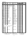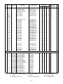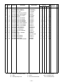
1
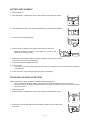
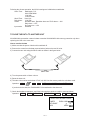
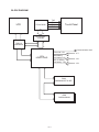
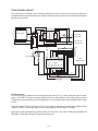
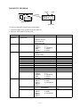
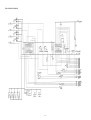
(without price)
NX-4000/6000
SEP. 1995
INDEX
R
CONTENTS
FEATURES .................................................................................................................... 1
SPECIFICATIONS ......................................................................................................... 2
BATTERY REPLACEMENT .......................................................................................... 4
REPLACING THE BACK-UP BATTERY ...................................................................... 4
RESET OPERATION ..................................................................................................... 5
TO SAVE THE DATA TO ANOTHER UNIT .................................................................. 6
BLOCK DIAGRAM ........................................................................................................ 8
TOUCH PANEL CIRCUIT.............................................................................................. 9
PIN FUNCTION............................................................................................................ 10
DIAGNOSTIC PROGRAM ........................................................................................... 11
MESSAGE TABLE ...................................................................................................... 15
SCHEMATIC DIAGRAMS ........................................................................................... 17
PARTS LIST ................................................................................................................ 21
EXPLODED VIEW ....................................................................................................... 24
FEATURES
• Pen-based graphic user interface
Simply tap on display icons and buttons to perform any operation.
• Color display
The display shows data in three colors: orange, blue, and green. Different colors can be used to highlight
specific dates in the Calendar.
• Desktop Menu System
Functions are represented by realistic icons that are arranged on a desk in your virtual office. Simple tap on
the icon that represents a function to access it.
• 256 kbytes (NX-6000) / 128 kbytes (NX-4000) of memory
You get enough memory to store up to 11,100 (NX-6000) / 5,200 (NX-4000) Telephone Directory items.
• Powerful data bank functions
Telephone Directory, Business Card Directory, Memo, Sketch, To Do, Expense Manager, Reminder, and
Schedule Keeper are at your fingertips throughout the day.
• Secret Drawer
A convenient place to lock up confidential information using a secret password.
• Calendar - Schedule Keeper - Reminder - To Do linking
Reminder and To Do items are automatically displayed in the applicable Schedule Keeper dates. Markers
appear on the Calender display to indicate dates for which Schedule Keeper, Reminder, and To Do items are
scheduled.
• Timepiece with Home Time and World Time
Dual timekeeping lets you keep track of the current time in two different locations.
• Powerful alarm functions
In addition to the standard daily alarm, you can also set alarms for Schedule Keeper, Reminder, and To Do
items.
• Calculator
A 12-digit arithmetic calculator is just the thing for those quick, on-the-go calculations.
• Data Communication
Exchange data with another NX Unit or with a CASIO SF Unit/CSF Unit.
—1—
SPECIFICATIONS
Storage Capacity
The 256K (NX-6000) / 128K (NX-4000) bytes memory capacity includes a 245,709 / 114,637-byte user area.
The following shows examples of what this means for the storage of data in each mode.
Telephone Directory
Approximately 11,100 / 5,200, under the following conditions:
8-character name
10-character telephone number
Approximately 5,700 / 2,600, under the following conditions:
8-character name
10-character telephone number
20-character address
Business Card Directory
Approximately 2,900 / 1,300, under the following conditions:
10-character employer name
8-character personal name
10-character telephone number
10-character position
10-character department
20-character address
Memo
Approximately 10,600 / 4,900, 20-character memos.
Sketch
Approximately 160 / 80
• The number of sketch pages that can be stored varies greatly according to the amount of data included
on each sketch page.
To Do
Approximately 6,100 / 2,800, under the following conditions:
20-character description
Illustration used
Deadline set
Schedule Keeper
Approximately 6,300 / 2,900, under the following conditions:
20-character description
Illustration used
Starting time specified, alarm time set
No sketch page data
Approximately 3,100 / 1,400, under the following conditions:
20-character description
Illustration not used
Starting time specified, no alarm time
One sketch page for every 30 text data items.
—2—
Reminder
Approximately 12,200 / 5,700, under the following conditions:
10-character description
Illustration used
Alarm time set
Approximately 14,400 / 6,700, under the following conditions:
10-character description
Illustration not used
No alarm time
Expense Manager
Approximately 7,400 / 3,400, under the following conditions:
10-character description
Expense type and Payment type set
General:
Display element:
21-column × 8-line LCD
Memory capacity:
256 KB (NX-6000), 128 KB (NX-4000)
Main component:
LSI
Power supply:
Main:
Back-up:
Two AAA-size batteries (Type: R03 (UM-4) or LR03 (AM4))
One CR2032 lithium battery
Battery life:
Main:
Back-up:
Approximately 110 hours continuous display in Telephone Directory (approximately
200 hours on type LR03 (AM4)); approximately 85 hours repeating one minute of
input and 10 minutes of display in Telephone Directory (approximately 150 hours on
type LR03 (AM4))
5 years if main batteries are replaced as soon as they becomes weak. 2 year if dead
main batteries are left in the unit.
Power consumption:
0.1 W
Auto power off:
Approximately 6 minutes after last key operation
Operating temperature: 0°C ~ 40°C (32°F ~ 104°F)
Dimensions:
Unfolded:
Folded:
14.7 H × 81.9 W × 225 D mm ( 9/16" H × 3 1/4" W × 8 7/8" D)
15.4 H × 81.9 W × 124 D mm ( 5/8" H × 3 1/4 W × 4 7/8" D)
Weight:
148 g (5.2 oz) including batteries
Current consumption:
Main Battery
ON (MENU):
OFF:
Backup Battery
Back-up:
MAX = 3.7 mA, TYP = 3.2 mA
MAX = 35 µA, TYP = 24 µA
Voltage detection:
Main battery:
Forced OFF:
Backup battery:
2.5 V ± 2.5 % or below
2.3 V ± 2.5 % or below
2.6 V ± 2.5 % or below
MAX = 10 µA, TYP = 6.3 µA
—3—
BATTERY REPLACEMENT
1. Switch power off.
2. Slide the battery compartment cover in the direction indicated by the arrow.
3. Slide the battery switch in the direction indicated by the arrow in the illustration.
4. Remove the main battery holder.
5. Remove both old batteries and replace them with two new ones.
•
Make sure that the positive (+) and negative (–) ends of the
batteries are facing correctly.
6. Replace the main battery holder, and slide the battery switch in the direction
indicated by the arrow in the illustration.
7. Replace the battery compartment cover.
8. Turn on power.
• The Home Time screen always appears whenever you turn power on for the first time after replacing
main batteries.
9. Check the Home Time setting and make changes if necessary.
REPLACING THE BACK-UP BATTERY
Before replacing the back-up battery, note the following precautions:
• Do not remove the back-up battery from the NX Unit while the main batteries are removed.
• Be sure to replace the back-up battery at least once 2 years. Otherwise, you run the risk of losing data
stored in memory.
1. Switch power OFF.
2. Slide the battery compartment cover in the direction indicated by the arrow.
3. Remove the screws that hold the back-up battery holder in place, and remove
the holder.
—4—
4. Remove the old battery and replace it with new one, making sure that the positive (+) side of the new battery
is facing up (so you can see it).
5. Replace the back-up battery holder and secure it by tightening its screw.
• Be careful that you do not over tighten the screw.
6. Replace the battery compartment cover.
RESET OPERATION
You can use either SECRET RESET or ALL RESET to initialize the NX Unit. ALL RESET deletes all data stored
in memory, while SECRET RESET deletes only the data stored in the secret drawer.
To perform ALL RESET
1. Switch power ON.
2. Open the battery compartment cover.
3. Press the RESET button with a thin, pointed object.
RESET button
•
At this time, the touch panel screen appears.
4. Tap the tip of the pencil icon as each one appears.
• When you tap the fourth pencil icon, the RESET screen appears.
Warning!
The next step deletes all data stored in the NX Unit's memory. Make sure that you really want to delete the
data before you continue!
5. Tap ALL RESET.
Note
• The message “ALL RESET? OK/ESC” always appears in English, regardless of the system language
setting.
6. Tap OK to reset the memory and delete all data or ESC to abort the reset operation without deleting
anything.
• After you tap OK, the system language screen appears.
7. Select the system language by tapping on the language you want to use, and then tap OK.
• After you select the system language, the Home Time screen appears.
8. Check the Home Time setting and make any changes that you want.
—5—
Following the all reset operation, the NX Unit settings are initialized as noted below.
Home Time:
World Time:
Daily Alarm:
Sound:
Input mode:
Washington, D.C.
JAN/1/1996 MON
12:00 AM
12-hour format
New York
12:00 PM
Schedule alarm, Reminder alarm and To Do alarm — ON
Daily alarm — OFF
Key input tone — ON
Overwrite
TO SAVE THE DATA TO ANOTHER UNIT
NX-4000/6000 can transfer customer's data to another NX-4000/6000 with memory protection only when
replacing the LCD or the outer case.
How to transfer the data
1) Make sure that the power of both units is switched off.
2) Remove the covers from the data communications jacks on the two NX units.
3) Connect the two units using the SB-62 cable as shown in the figure below.
SB-62 cable
4) Turn the power switch of slave units on.
5) Reset the slave unit.
6) The slave unit must be set the date of Feb. 3rd, 1901 into the memory under the calculator mode.
Operation : ON
AC
1
DATE
2
DATE
3
DATE
M+
If you don't set the date, the "PASSWORD" isn't transferred to the slave unit.
7) Check the hardware parameters, and if the both units have another condition, reset as follows;
Operation : MENU
FUNC
DATA COM.
SET UP PAR.
NONE
7
9600
OK
//////////// SET UP PAR. ////////////
PARITY
BIT LENGT
BPS
—6—
EVEN ODD NONE
7
8
4800 / 9600
8) Set up the slave unit.
Operation : MENU
FUNC
DATA COM.
RECEIVE
RECEIVE OK!
DATA
TO STOP
PRESS
[ ESC ]
OK ESC
9) Set up the customer's unit.
• Turn the power switch off.
• Press the RESET button with a thin, pointed object while shorting the following pad.
Enlarge
SEND ALL DATA ?
OK
ESC
BOTTOM VIEW
Short the pad
Note: Be careful not to reset the customer's unit. If “DIGITIZER” is displayed, turn the power switch off
immediately, and try again.
10) Start the data communication (slave unit).
Operation : OK
RECEIVING
ITEMS 00001
RECEIVE OK!
DATA
TO STOP
PRESS
[ ESC ]
OK ESC
If you can not succeed to transfer the data, press ESC key on both unit and try to transfer the data again
according to the above procedure.
—7—
BLOCK DIAGRAM
LCD
TXR
TXL
TYU
TYD
TC74LCX240
Touch Panel
AD converter
TC35093
TAB LSI
uPD3062W
Communication Jack
Forced off 2.3V
CPU
HD62119A03
Main battery
Low battery 2.5V
Back uo battery
Low battery 2.6V
Detector : IC7
Detector : IC6
Detector : IC8
ROM
MB834000CPF-G-4EP
RAM
CXK581000AM
—8—
TOUCH PANEL CIRCUIT
Four electrodes are installed in top and bottom right and left of panel, and the touch panel recognizes the
coordinate which was pushed with a pen on panel by detecting change volume of current which flowed through
panel by pushing panel.
AAAA
AAAAAAAA
AAAAAAAA
X1
Y1
TOUCH PANEL
TC74LCX240
TYU
Y2
TXR
1Y
1G-
2A
2G-
TYD
2Y
1A
TXL
KO8(TABXG)
KO6(TABLUB)
KO5(TABRDB)
X2
11
AGND
12
OE
CPU
HD62119A03
OVF
9
VSS
10
AIN
DB7
CS8B
DB3
DB2
DB1
DB0
DB7
DB6
DB5
DB4
8
DB6
6
7
VREF
14
13
15
DB1
DB0
17
16
DB2
NC2
5
DB5
TC35093
4
DB4
STC
3
1
2
CK
IC82
NC1
18
DB3
EOC
20
VDD
19
VDD
TC74HC4066
KO7(TABYG)
ADCH
ADSTOB
ADSTBY
OCLK
Circuit Operation
TXL and TYU of drive signals are sent through LS240 from CPU by X1,Y1 of touch panel when turn on power
supply. And, TXR,TYD signals are output through LS240 from touch panel to AIN terminal of A/D converter
TC35093, and convert the analog value into digital value, and TC35093 outputs digital data DB0~DB7 of 8 bits
to CPU.
TC35093 changes TXR of X axis signal, TYD of Y axis signal in alternating by analog switch 4066 by ADCH
signal from CPU to output digital data, and input analog data into AIN terminal of TC35093.
Synchronize analog data input from AIN terminal in clock signal of 1 pin, and TC35093 outputs digital data
DB0~DB7 to CPU when OE and STC signal input become H.
—9—
PIN FUNCTION
CPU (HD62119A03)
Pin No.
1
2
3
4
5
6
7
8
11
12
13, 18 ~ 20
21
22, 23
24 ~ 42
43
44
45
46
47
48
49
50
51
52 ~ 59
60, 61
62
63
64 ~ 71
72
73
74
75
76
77
78
79
80, 81
82
83, 84
85
86
87
88
89
90
91 ~ 94
95
96
97
98
99
100
Pin Name
KO12
KO
KO10
KO9
KO8
KO7
KO6
KO5
KO2
KO1
KI8, 3 ~ 1
BUFON
IT2, 1
AO18 ~ 0
OEBO
WEBO
CS10BO
CS9BO
CS8BO
CS7BO
CS6BO
CSB5O
CS4BO
IO7 ~ 0
OPT3, 2
OPT1
OPT0
PORT7 ~ 0
VSS
PI
PO
VLC
XO
XI
VCC
VREG2
TS1, TS2
VSSR
BZZ1, 2
VSS
OCLK
ITOFF
TEMU
SW
VDB
VD1 ~ 4
VREG1
VREG4
VREG5
VDT1I
VDT2I
VREG3
Input / Output
O
O
O
O
O
O
O
O
O
O
I
O
I
O
O
O
O
O
O
—
O
O
O
I/O
—
O
—
I/O
I
I
O
—
O
I
I
I
I
I
O
I
O
I
I
I
I
I
I
I
I
I
I
I
Function
Key common signal
Switching signal for Xaxis and Y axis
Strobe signal for AD converter
Standby signal for AD converter
Switching signal for TXR and TXL
Switching signal for TYU and TYD
Touch panel driving signal for TXL and TYU
Touch panel driving signal for TXR and TYD
Key common signal for TEST pad
Key common signal for ON key
Key in signal
Chip select signal
Interrupt input
Address signal
Output enable
Write enable signal
Address signal (A19)
Address signal (A20)
Output enable signal
Check pad
Chip select signal
Chip select signal
Chip select signal
Data bus
Check pad
Chip select signal
Check pad
I/O port
GND
Ceramic oscillation input
Ceramic oscillation output
Power terminal
Crystal oscillation output
Crystal oscillation input
+3V source
Voltage regulator input
Test terminal
GND
Buzzer signal output
GND
Clock signal output
Power off terminal
Test terminal
Reset switch terminal
Back up power terminal
Power for dubler
Regulator power
Regulator power
Regulator power
Voltage detector 2.3V
Voltage detector 2.5V
Regulator power
— 10 —
DIAGNOSTIC PROGRAM
CP55
CP38
Enlarge
BOTTOM VIEW
TEST PAD
To enter the diagnostic program, proceed as follows;
1: Open the battery cover and turn the power switch on.
2: Short the TEST pads CP38 and CP55.
STEP
Enter the
diagnostics
OPERATION
Press on and then short
the TEST pad.
Main menu
Tap anywhere
DIsplay Check
1 DISPLAY
1 DISPLAY
Tap anywhere
Tap anywhere
Tap anywhere
Tap anywhere
Tap anywhere
Tap anywhere
Tap anywhere
Tap anywhere
Tap anywhere
Tap anywhere
Memory Check 2 MEMORY
DISPLAY
SELF TEST PROG
NOTE
PRESS any TOUCH
QUIT BY OFF KEY
CASIO JULY 1995
TEST MENU
5 I/F
1 DISPLAY
6 CONTRAST
2 MEMORY
7 TOUCH
3 TIME
8 RESET
4 BUZZER
DISPLAY
1 DISPLAY
2 FRAME FREQ.
No color, no display
Orange color is displayed
Green color is displayed
Blue color is displayed
Checkers are displayed
Reverse checkers are displayed
Frame is displayed
Dots at the 4 corners are displayed
Vertical 4 colors are displayed
Horizontal 4 colors are displayed
TEST MENU
1 DISPLAY
5 I/F
2 MEMORY
6 CONTRAST
3 TIME
7 TOUCH
4 BUZZER
8 RESET
MEMORY
1 WRITE 1
5 DUMP
2 READ 1
6 CHECKSUM
3 WRITE 2
4 READ 2
1 WRITE 1
RAM WRITE 1
1
2
3
4
MEMORY
WRITE 1
READ 1
WRITE 2
READ 2
— 11 —
5 DUMP
6 CHECKSUM
Write the test pattern 1 into
RAM
After 3 sec.
STEP
OPERATION
2 READ 1
DISPLAY
EXECUTING !!
CMPLETE !!
XXXkB
Tap anywhere
1
2
3
4
MEMORY
WRITE 1
READ 1
WRITE 2
READ 2
RAM WRITE 2
4 READ 2
MEMORY
WRITE 1
READ 1
WRITE 2
READ 2
5 DUMP
Memory Check Tap anywhere
6 CHKSUM
Tap anywhere
ESC
Time Check
3 TIME
ESC
Write the test pattern 2 into
RAM
After 3 sec.
5 DUMP
6 CHECKSUM
EXECUTING !!
CMPLETE !!
XXXkB
Tap anywhere
After 3 sec.
NX-4000 : 128kB
NX-6000 : 256kB
5 DUMP
6 CHECKSUM
3 WRITE 2
1
2
3
4
NOTE
Read the test pattern 1
from RAM
MEMORY
1 WRITE 1
2 READ 1
3 WRITE 2
4 READ 2
CHKSUM OS
SUM XXXX
MEMORY
1 WRITE 1
2 READ 1
3 WRITE 2
4 READ 2
CHECK SUM
TYPE CS5
SIZE
1024kB
SUM XXXX
EXOR XX
MEMORY
1 WRITE 1
2 READ 1
3 WRITE 2
4 READ 2
TEST MENU
1 DISPLAY
2 MEMORY
3 TIME
4 BUZZER
TIME
00:00:00
TEST MENU
1 DISPLAY
2 MEMORY
3 TIME
4 BUZZER
— 12 —
Read the test pattern 2
from RAM
After 3 sec.
NX-4000 : 128kB
NX-6000 : 256kB
5 DUMP
6 CHECKSUM
Wiring check for ROM
5 DUMP
6 CHECKSUM
Check SUM value
5 DUMP
6 CHECKSUM
5
6
7
8
I/F
CONTRAST
TOUCH
RESET
5
6
7
8
I/F
CONTRAST
TOUCH
RESET
STEP
Buzzer Check
OPERATION
4 BUZZER
ESC
Interface Check 5 I/F
DISPLAY
BZZ
1 BEEP
2 ALARM 1
3 ALARM 2
TEST MENU
1 DISPLAY
5 I/F
2 MEMORY
6 CONTRAST
3 TIME
7 TOUCH
4 BUZZER
8 RESET
I/F
1 TRANS
7
2 RECEIVE
N
3 ASCII
9
4 LOOP
1 TRANS
2 RECEIVE
EXECUTING !!
No display
3 ASCII
ESC
The parameter can be
changed
as follows;
"7" : Bit length 7 or 8 bit
"N" : Parity bit N(Non),
E(Even) or O(Odd)
"9" : BPS 9(9600) or
4(4800)
Send the code "H"
Display the received
charactor.
EXECUTING !!
4 LOOP
NOTE
1 : Key input sound
2 : Sound alarm 1
3 : Sound alarm 2
EXECUTING !!
I/F
TRANS
7
RECEIVE
N
ASCII
9
LOOP
TEST MENU
1 DISPLAY
5 I/F
2 MEMORY
6 CONTRAST
3 TIME
7 TOUCH
4 BUZZER
8 RESET
CONTRAST
INIT
Send the ASCII code
Loop back check
1
2
3
4
CONTRAST
ADJ.
6 CONTRAST
Contrast up : Tap
Contrast adjustment
(ORG)
Contrast down : Tap
(BLU)
(GRN)
Color up : Tap
Color down : Tap
INIT
CONTRAST
(ORG)
(BLU)
(GRN)
ESC
1
2
3
4
TEST MENU
DISPLAY
MEMORY
TIME
BUZZER
— 13 —
5
6
7
8
I/F
CONTRAST
TOUCH
RESET
Adjust the color using
cursor keys until the
primary colors appear
accurately.
STEP
OPERATION
TOUCH PANEL 7 TOUCH
ADJUSTMENT
DISPLAY
1 ADJUST
/////DIGITIZER//////
TAP THE TIP OF THE
PENCIL ICON
Tap 4 pencil icons.
NOTE
touch TEST
1 ADJUST
2 TEST
Tap the tip of the pencil
icon.
When you do, the pencil
icon you tapped
disappears, and the next
one appears.
Tap 4 pencil icons.
touch TEST
1 ADJUST
2 TEST
2 TEST
Tap 4 pencil icons.
/////DIGITIZER//////
TAP THE TIP OF THE
PENCIL ICON
Trace the horizontal black
line and then vertical black
line.
ESC
[ OK ]
ESC
ESC
Reset
8 RESET
touch TEST
1 ADJUST
2 TEST
TEST MENU
1 DISPLAY
2 MEMORY
3 TIME
4 BUZZER
MAIN MENU
5
6
7
8
I/F
CONTRAST
TOUCH
RESET
CONTRAST ADJUSTMENT
1 : Enter the diagnostic program and tap "6 : CONTRAST".
2 : Look the LCD from heading.
3 : Adjust the volume VR1 on the Z850-1 pcb ass'y.
4 : As to the step of hereafter, refer to "DIAGNOSTIC PROGRAM" mentioned above
— 14 —
MESSAGE TABLE
Message
Meaning
Action
NOT FOUND!
Data specified in search operation does
not exist in memory.
Change specification or cancel search.
MEMORY FULL!
Not more room in memory for storage
of data.
Delete unnecessary data items from
memory.
ALARM TIME
ALREADY USED!
Attempt to set a Schedule Keeper,
Reminder or a To Do alarm time that is
already used for another entry.
Set a different alarm time or change
the existing alarm time to another one.
ALARM TIME
ALREADY
PASSED!
Attempt to set a Schedule Keeper, a
Reminder or a To Do alarm time for a
time/date that is already passed.
Set a different alarm time (for a future
time/date).
SECRET DATA!
Alarm for a secret memory area data
item is sounding.
Enter the secret memory area to view
details of the alarm.
PASSWORD
MISMATCH!
Attempt to enter the secret memory
area using a password that does not
match the one preset for the secret
area.
Use the correct password.
TRANSMIT ERROR!
Error during data communications.
Cancel the data communications operation and try again.
STOPPED!
Data communication has been interrupted.
Stop the data communication procedure and try again.
NOTICE!
CONSULT THE
OWNER'S MANUAL!
• This message appears when this is
the first time you ever turned on the
NX Unit.
• Data corrupted by strong impact,
electrostatic charge, etc.
Perform the ALL RESET operation
(“Resetting the NX Unit's Memory” in
Character 1).
See “About the “NOTICE!” message”
in Chapter 1.
— 15 —
SCHEMATIC DIAGRAMS
Z850-1 PCB ASS'Y (MAIN BLOCK)
— 17 —
Z850-1 PCB ASS'Y (A/D BLOCK)
— 18 —
Z850-1 PCB ASS'Y (DISPLAY BLOCK)
— 19 —
Z850-1 PCB ASS'Y (MEMORY BLOCK)
— 20 —
PARTS LIST
N
Item
Code No.
Parts Name
Specification
AE
Z850-1 PCB ASS'Y
28
6511 0770 Battery spring K-L538AA
30
6409 9960 Battery spring A-L525AM
N
34
6415 8590 Battery spring A-Z850AH
N
35
6415 8600 Battery spring C-Z850AH
CN1
3501 8547 Connector
D1,5
2390 0364 Schottky diode
D30
2390 1561 Chip diode
D4
2390 0875 Chip diode
D6,7
2390 1442 Chip diode
N IC1,84 2114 4683 CMOS-IC
N
IC10
2105 5012 CMOS-IC
N
IC11
2105 4704 CMOS-IC
N
IC30
2105 5096 CMOS-IC
N
IC4
2105 2737 CMOS-IC
N
IC6
2105 4228 CMOS-IC
N
IC7
2105 4914 CMOS-IC
N
IC8
2105 4144 CMOS-IC
N
IC81
2105 5040 CMOS-IC
N
IC82
2105 5089 CMOS-IC
N
IC83
2105 5033 CMOS-IC
N
IC87
2105 5005 CMOS-IC
N IC88,9,12 2114 4676 CMOS-IC
IC89
2105 1827 CMOS-IC
J1
3501 6538 Mini jack
LSI2
6413 5320 COF3011-F1 sub ass'y
N LSI3,4 2012 1659 LSI
N
LSI5
2012 2380 LSI
Q5
2254 0287 FET
Q6,7
2259 0959 Chip digital transistor
Q70
2250 0546 Chip transistor
Q8
2250 0826 Chip transistor
Q81
2221 2451 Chip transistor
THR1 2755 0147 Thermistor
N
VR1
2765 1869 Chip volume
X1
2590 1967 Ceramic oscillator
X2
7110 0642 Crystal
N
L1
3841 1799 Coil
C311380-1
C413299-1
C440621-1
C440622-1
IL402-4S-E1000
MA713-TX
MA724-(TX)
MA704-(TX)
MA152K-(TX)
TC74HC4066AFS(EL)
HD74HC32T-EL
RH5RE25AA-T1
XC6382A501PR
RH5RL50AA-T1
RH5VL25CA-T1
RH5VL23CA-T1
RH5VL26CA-T1
XC62AP3002PR
TC35093FS(EL)
TC74LCX240F(EL)
HD74HC04T-EL
TC7W04FU-TE12L
TC7S02F-TE85R
HSJ1169-012010
A340214*1
TC551001BFL-10V(S)
uPD27C4001GW-73202
2SK1133-T1B
DTC114YKT-146
2SA1411T1B M15,M16
2SA1179M6,M7-TB
2SC2812L5,L6,L7-TB
104HT
MVR32HXBRN503
CSTC4.30MG-TC
DT-26S
636CY-151M-P3
Quantity
M
EE AEU EEU
1
1
1
1
1
2
1
1
2
2
0
1
1
1
1
1
1
1
1
1
1
3
1
1
1
1
1
1
2
1
1
1
1
1
1
1
1
1
1
1
1
1
2
1
1
2
2
1
1
1
1
1
1
1
1
1
1
1
3
1
1
1
2
1
1
2
1
1
1
1
1
1
1
1
1
1
1
1
1
2
1
1
2
2
0
1
1
1
1
1
1
1
1
1
1
3
1
1
1
1
1
1
2
1
1
1
1
1
1
1
1
1
1
1
1
1
2
1
1
2
2
1
1
1
1
1
1
1
1
1
1
1
3
1
1
1
2
1
1
2
1
1
1
1
1
1
1
1
FOB Japan
N.R.Yen
R
Unit Price
20
20
20
20
10
10
10
20
20
5
10
5
1
10
10
10
10
5
1
1
10
5
10
5
1
1
1
20
20
20
20
20
5
20
1
10
5
The following elecrical parts will be not supplied from CASIO.
C2,5,6,
C35,39,
C66,82,
C84,90,
CB1,CB2
C3,4,9,
C12,19,
C20,51,
C52,53,
C54,55
C7
Notes: N
M
R
Q
–
–
–
–
Chip capacitor
MCH183F104ZK
11
11
11
11
Chip capacitor
MCH312F105ZP
11
11
11
11
Chip tantalum capacitor
New parts
R–A:
Minimum order/supply quantity
B:
C:
Rank
X:
Quantity used per unit
ECST1AY106R
Essential
Stock recommended
Others
No stock recommended
— 21 —
1
1
1
AEU :
AE :
EEU :
EE :
1
NX-4000 (U.S.A)
NX-4000 (Others)
NX-6000 (U.S.A)
NX-6000 (Others)
X
X
X
X
X
C
C
C
C
B
B
B
B
B
B
B
B
B
B
B
B
B
B
C
A
A
A
B
B
B
B
B
C
C
C
C
C
N
Item
C10,11
C18
C33
C34
C37
C41,42
C56,57,
C58,59,
C60,61
C81
R1
R2
R3,27,77
R16
R17
R18
R19
R20
R22
R23
R25
R27
R28
R31
R33,95
R34
R36,71,
R72,73,
R84
R50
R85,21,
(32)
R86
R87
R90
N
N
N
N
N
N
N
N
N
N
N
N
N
N
N
N
1
2
2
3
3
4
5
5
6
7
7
8
9
10
11
12
Notes: N
M
R
Q
Code No.
Parts Name
Specification
AE
2
1
1
1
1
2
6
Quantity
M
EE AEU EEU
2
2
2
1
1
1
1
1
1
1
1
1
1
1
1
2
2
2
6
6
6
Chip capacitor
Tantalum capacitor
Electrolytic capacitor
Electrolytic capacitor
Chip capacitor
Chip capacitor
Chip capacitor
MCH212F474ZP
ECST0JY106R
UMR0J101MDA1TP
ECEA1AKS101I
MCH185A221JK
MCH185A160JK
MCH212C154KP
Electrolytic capacitor
Chip resistor
Chip resistor
Chip resistor
Chip resistor
Chip resistor
Chip resistor
Chip resistor
Chip resistor
Chip resistor
Chip resistor
Chip resistor
Chip resistor
Chip resistor
Chip resistor
Chip resistor
Chip resistor
Chip resistor
ECE-A0JKS470I
MCR03EZHJ153
MCR03EZHJ154
MCR03EZHJ473
MCR03EZHG392
MCR03EZHG822
MCR03EZHG102
MCR03EZHG202
MCR03EZHF1053
MCR03EZHF5622
MCR03EZHF1003
MCR03EZHJ182
MCR03EZHJ102
MCR03EZHG105
MCR03EZHJ475
MCR03EZHJ105
MCR03EZHJ273
MCR03EZHJ823
1
1
1
3
1
1
1
1
1
1
1
1
1
1
1
2
1
5
1
1
1
3
1
1
1
1
1
1
1
1
1
1
1
2
1
5
1
1
1
3
1
1
1
1
1
1
1
1
1
1
1
2
1
5
1
1
1
3
1
1
1
1
1
1
1
1
1
1
1
2
1
5
Chip resistor
Chip resistor
MCR03EZHJ184
MCR03EZHJ000
1
3
1
2
1
3
1
2
MCR03EZHJ300
MCR03EZHJ104
MCR03EZHJ333
1
1
1
1
1
1
1
1
1
1
1
1
C440972-1
C140155-6
C140155-8
C440636-2
C440636-6
C440634-1
C140152-6
C140152-8
C440639-1
C340435-2
C340435-6
C240260-1
C440637-1
C340413-1
C440620-1
C440633-1
Essential
Stock recommended
Others
No stock recommended
1
1
0
0
1
1
1
0
1
1
0
1
2
1
1
1
1
1
0
1
1
0
1
0
0
1
1
1
0
1
1
0
1
1
0
1
1
0
1
1
2
2
1
1
1
1
1
1
AEU :
AE :
EEU :
EE :
Chip resistor
Chip resistor
Chip resistor
COMPONENT
6416 5860 Label Z850
6415 9620 Hard cover Z853AE
6416 0990 Hard cover Z853EE
6415 8850 Blind label Z852AE
6415 9640 Blind label Z853AE
6415 8630 Plate M-Z850AH
6415 9370 Upper case Z853AE
6416 0920 Upper case Z853EE
6415 8680 Battery spring B-Z850AH
6415 8840 Key top Z852AE
6416 5670 Key top Z853EE
6415 8470 Middle case Z850AH
6415 8660 Tape C-Z850AH
5610 8860 Heat seal C-Z850AH
6415 8580 Magnet Z850AH
6415 8620 Cushion M-Z850AH
– New parts
R–A:
– Minimum order/supply quantity
B:
C:
– Rank
X:
– Quantity used per unit
— 22 —
FOB Japan
N.R.Yen
R
Unit Price
1 20
0 1
1 1
1 20
0 20
1 20
0 1
1 1
1 20
0 20
1 20
1 10
2 20
1 1
1 1
1 20
NX-4000 (U.S.A)
NX-4000 (Others)
NX-6000 (U.S.A)
NX-6000 (Others)
X
C
C
X
X
X
C
C
C
C
C
C
X
B
C
X
N
N
N
N
N
N
N
N
N
N
N
N
N
N
N
N
N
N
N
N
N
N
N
N
N
N
Item
13
14
14
15
16
17
18
19
20
20
20
20
21
22
22
23
23
24
25
26
27
29
31
31
32
33
Notes: N
M
R
Q
Code No.
6415 8490
6415 9560
6416 1000
6390 0432
6410 0150
6415 8520
6511 4881
6408 3740
6415 9610
6416 0980
6416 3510
6416 3520
6415 8610
6415 9380
6416 0940
6416 0900
6415 9320
6415 8560
5610 8850
3335 5943
6415 8690
3122 2380
6415 8830
6415 9630
6415 8460
6415 8670
–
–
–
–
Parts Name
Inner rubber Z850AH
Z850-1 PCB ass'y
Z850-1 PCB ass'y
Cap V332
Contact spring L525AM
Battery switch Z850AH
Rubber key L538AA
Nut L72
Lower case Z853AE
Lower case Z854EE
Lower case Z855AEU
Lower case Z853EEU
Battery plate M-Z850AH
Battery cover Z853AE
Battery cover Z854EE
Touch panel ass'y
Touch panel ass'y
Tape S-Z850AH
Heat seal S-Z850AH
LCD
Cushion L-Z850AH
Buzzer
Hinge Z852AE
Hinge Z853AE
Pen Z850AH
Battery plate B-Z850AH
New parts
R–A:
Minimum order/supply quantity
B:
C:
Rank
X:
Quantity used per unit
Specification
C340428-1
C140167E*5 C
C140167E*6 C
A310765B-1
C412167-2
C340433-1
A311024A-2
A411563-3
C140153-4
C140153-6
C140153-8
C140153-9
C440623-1
C340427-4
C340427-5
C340445*3 C
C340445*2 C
C440618-1
C340412-1
CD1030-TS
C440640-1
EFB-S55C41A8
C340431-2
C340431-6
C240259-1
C440638-1
Essential
Stock recommended
Others
No stock recommended
— 23 —
AE
1
1
0
1
1
1
1
1
1
0
0
0
1
1
0
0
1
2
1
1
2
1
0
1
1
1
FOB Japan
Quantity
M N.R.Yen
EE AEU EEU
Unit Price
1
1
1 20
0
1
0 1
1
0
1 1
1
1
1 20
1
1
1 20
1
1
1 20
1
1
1 20
1
1
1 20
0
0
0 5
1
0
0 1
0
1
0 5
0
0
1 5
1
1
1 20
0
1
0 5
1
0
1 5
1
0
1 1
0
1
0 1
2
2
2 20
1
1
1 10
1
1
1 1
2
2
2 20
1
1
1 10
1
0
1 5
0
1
0 5
1
1
1 10
1
1
1 20
AEU :
AE :
EEU :
EE :
NX-4000 (U.S.A)
NX-4000 (Others)
NX-6000 (U.S.A)
NX-6000 (Others)
R
C
B
B
X
X
C
C
X
C
C
C
C
C
C
C
B
B
X
B
B
X
X
C
C
C
X
EXPLODED VIEW
1
23
2
3
4
5
6
24
7
25
8
26
9
10
27
11
12
13
14
34
28
35
29
15
30
16
31
17
18
32
19
20
21
22
33
— 24 —
8-11-10, Nishi-Shinjuku
Shinjuku-ku, Tokyo 160, Japan
Telephone: 03-3347-4926