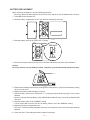
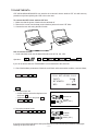
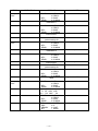
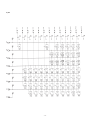
1
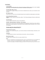
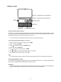
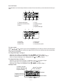
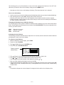
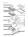
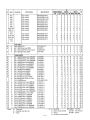
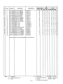
(without price)
CSF-4450A/4650A/4950A/
4970A (ZX-888)
JUN. 1996
CSF-4970A
INDEX
R
CONTENTS
FEATURES ..............................................................................................................................1
SPECIFICATIONS ...................................................................................................................2
GENERAL GUIDE ...................................................................................................................4
BATTERY REPLACEMENT ....................................................................................................7
RESET OPERATION ...............................................................................................................8
TO SAVE THE DATA .............................................................................................................. 9
PIN FUNCTION ...................................................................................................................... 10
DIAGNOSTIC PROGRAM ..................................................................................................... 11
ERROR MESSAGE ...............................................................................................................14
SCHEMATIC DIAGRAMS ..................................................................................................... 15
EXPLODED VIEW .................................................................................................................19
PARTS LIST ..........................................................................................................................20
FEATURES
3-color Display
The display shows data in three colors: orange, blue and green. Different colors can be used to highlight
specific dates in the Calendar, and even the color of text data can be specified.
Selectable Main Menu Format
Choose between a graphic desktop or an icon list for the Main Menu from which you can select the mode
you want.
Do Today Function
Every time you turn on the unit, any Schedule Keeper items scheduled for that date appear on the display.
Powerful Data Bank Functions
Telephone Directory, Business Card Directory, Memo, To Do, Expense Manager, Reminder, and Schedule
Keeper.
Secret Function
Look up confidential information using a secret password.
Calendar - Schedule Keeper - Reminder - To Do Linking
Reminder and To Do items are automatically displayed in the applicable Schedule Keeper dates. Markers
appear on the Calendar display to indicate dates for which Schedule Keeper, Reminder, and To Do items
are scheduled.
Timepiece with Home time and World Time
Dual timekeeping for two different locations.
Powerful Alarm Functions
In addition to the standard daily alarm, you can also set alarms for Schedule Keeper, Reminder, and To
Do items.
Calculator
A 12-digit arithmetic calculator is just the thing for those quick, on-the-go calculations.
Data Communication
Exchange data with another CSF Unit or with a CASIO SF Unit.
Note
• This unit is equipped with a demonstration feature, which is activated before the unit is shipped from
the factory. Be sure to turn the demonstration off before using the unit for normal operation.
If you don't, any display color balance settings you make will be cleared every time you turn the unit off.
—1—
SPECIFICATIONS
Memory Capacity
Memory capacity differs according to model. The following shows the memory capacity for each available
model.
Model
Memory
CSF-4450A
32K bytes
CSF-4650A
64K bytes
CSF-4950A
128K bytes
CSF-4970A
256K bytes
The following shows the number or items that can be stored in each model (CSF-4450A/4650A/4950A/
4970A).
Telephone Directory
Approximately 1,200/2,700/5,700/11,600, under the following conditions:
8-character name
10-character telephone number
Approximately 600/1,300/2,900/5,900, under the following conditions:
8-character name
10-character telephone number
20-character address
Business Card Directory
Approximately 300/700/1,500/3,000, under the following conditions:
10-character employer name
8-character personal name
10-character telephone number
10-character position
10-character department
20-character address
Memo
Approximately 1,100/2,600/5,400/11,100, 20-character memos.
To Do
Approximately 700/1,600/3,400/7,100, under the following conditions:
20 character description
Deadline set
Schedule Keeper
Approximately 700/1,500/3,200/6,500, under the following conditions:
20 character description
Illustration used
Starting time specified, alarm time set
Approximately 900/2,000/4,100/8,500, under the following conditions:
20 character description
Illustration not used
Starting time specified, no alarm time
Reminder
Approximately 1,500/3,300/6,900/14,200, under the following conditions:
10 character description
Alarm time set
Approximately 1,700/3,700/7,800/16,000, under the following conditions:
10 character description
No alarm time
—2—
Expense Manager
Approximately 800/1,800/3,800/7,700, under the following conditions:
10 character description
Expense type and payment type set
Main Modes:
Telephone Directory, Business Card Directory, Memo, Schedule Keeper, To Do, Expense Manager,
Reminder, Calendar, Home Time, World Time and Calculator
Data Storage:
Storage and recall of telephone, business card, memo, schedule, to do, expense, reminder data; calendar
display; secret memory area; editing; memory status display
Clock:
Worldtime; reminder alarm; schedule alarm; to do alarm; daily alarm; accuracy under normal temperatures:
±3 seconds average
Calculation:
12-digit arithmetic calculations; arithmetic constants (+, -, ×, ÷); independent memory; percentages; square
roots; 24-digit approximations; date calculations; other mixed calculations
General:
Display element:
16-column × 4-line LCD
Main component:
LSI
Power supply:
Three lithium batteries (CR2032)
Current consumption:
ON:
OFF:
1.6 mA or under (TEL mode)
13 µA or under
Low battery message:
7.2 V ± 2.0%
Forced power off:
6.7 V ± 2.0%
Battery life:
Main:
Approximately 90 hours continuous display in Telephone Directory; approximately
70 hours repeating one minute of input and 10 minutes of display in Telephone
Directory
Power consumption:
Auto power off:
0.08 W
Approximately 6 minutes after last key operation
Operating temperature:
0°C ~ 40°C (32°F ~ 104°F)
Dimensions:
Unfolded:
Folded:
10.7H × 145W × 174.5D mm (7/16"H × 511/16"W × 67/8"D)
15.3H × 145W × 89.5D mm (5/8"W × 511/16"W × 31/2"D)
Weight:
125 g (4.4 oz) including batteries
—3—
GENERAL GUIDE
OFF key - Press this key to turn power off.
ON key - Press this key to turn power on.
Display
Cursor Key Pad
Keyboard
MENU key
COLOR SELECT keys
About the Demonstration feature...
The CSF Unit comes with a Demonstration feature that shows sample screens and input data for each of
its functions. When the Demonstration feature is turned on, the CSF Unit automatically shows the various
demonstration screens in sequence each time you turn it on.
• You can interrupt an ongoing demonstration at any time by pressing any key.
To turn the Demonstration feature on and off
1. While the main menu is on the display, press FUNC.
2. Press 1 to select SYSTEM.
3. Press
to display the second SYSTEM Menu.
4. Press 2 to select START UP.
5. Use
and
to move the pointer to DEMO.
6. Use
and
to turn the Demonstration feature on and off.
7. After making the setting you want, press OK.
Note
• The demonstration feature screens will not be displayed when the Do Today feature is turned on.
Selecting a Main Menu Format
You can select either a graphic desktop or an icon list as the Main Menu format. You get the same features
and functions, regardless of the Main Menu format you select.
Important!
• All of the examples in this manual are illustrated using the icon list, and all references to the Main Menu
apply to both the graphic desktop and the icon list, unless otherwise specified.
—4—
Icon List Format
The Main Menu icon list format provides two screens of icons from which you can choose the function you
want.
1
2
3
4
5
6
1 Telephone Directory
2 Business Card Directory
3 Memo
7
4 To Do
5 Schedule Keeper
6 Calendar
7 Expense Manager
1
2
3
4
5
6
1 Reminder
2 Home Time
3 World Time
4 Daily Alarm
5 Calculator
6 Secret Memory Area
To enter a mode
cursor keys to move the highlighting to the mode you want to select and press
Use the , , , and
OK. Or you can simply input the number in the upper left corner of an icon to directly enter the corresponding
mode without pressing OK.
To change from Page 1 to Page 2
• While any icon of Page 1 is highlighted, press or MENU to change to Page 2.
• While an icon in the bottom row of Page 1 is highlighted, press
to change to Page 2.
• While the Expense Manager icon is highlighted, press
to change to Page 2.
To change from Page 2 to Page 1
• While an icon in the top row of Page 2 is highlighted, press
to change to Page 1.
• While the Reminder icon is highlighted, press
to change to Page 1.
• While any icon of Page 2 is highlighted, press or MENU to change to Page 1.
Desktop Format
Calendar, Schedule
Keeper, Reminder and
Expense Manager
Home Time, World
Time, and Alarm
Calculator
Telephone Directory
and Business Card
Directory
Secret Drawer
To Do
—5—
Memo
The desktop gives you point-and-select access to the data management features of the CSF Unit.
Whenever you want to return to the desktop, simply press the MENU button.
• Note that one of the icons on the desktop is flashing, This means that the icon is selected.
How to use the desktop
1. Use the cursor keys to move the flashing around the desktop until the one you want is selected (flashing).
2. After selecting an icon, press OK to access the functions of that icon.
• Selecting some icons (like the Clock and Telephone) cause another selection screen to appear.
• Details on actually using the features and functions that you access from the desktop are described in
the other sections of this manual.
Changing the Desktop Screen's Window Scenery
You can change the scenery that is outside the desktop screen's window to any one of the scenes shown
below. Simply display the desktop screen and press the COLOR SELECT key that corresponds to the
scenery you want to select.
ORG:
BLU:
GRN:
Night-time city scene
Daytime city scene
Beach scene
Adjusting the Color Balance
The following procedure describes how to adjust the color contrast, which controls the relative darkness
and lightness of each color on the display.
To adjust the Color Balance
1. While the desktop is on the display, press FUNC.
2. Press 1 to select SYSTEM.
3. Press
to display the second SYSTEM menu.
4. Press 1 to select COLOR BALANCE.
Pointer (currently
selected item)
5. Use
and
(ORG)
(BLU)
(GRN)
INITIALIZE
to move the pointer to the color whose contrast you want to set.
6. Use
and
to adjust the contrast of the currently selected color.
• You can adjust the overall contrast of the display by pressing or .
7. After you finish adjusting the display contrast, press OK.
• Color contrast settings are registered as soon as you make them. Because of this, pressing either OK
or ESC quits the color contrast procedure only. Pressing ESC does not return the color contrast setting
to what is was.
Note
• Temperature changes can cause changes in background color and the tint of display colors .
—6—
BATTERY REPLACEMENT
Before replacing the batteries, note the following precaution:
• Be sure to replace all batteries with a full set of new ones, and do not mix old batteries with new ones.
1. Press OFF to switch power OFF.
2. Slide the battery compartment cover in the direction indicated by the arrow.
+3
2
+
1
+
3. Slide the battery switch to the "REPLACE 1" setting.
REPLACE
+3
3
2
1
2
+
1
+
NORMAL
4. Remove the battery holder by sliding it in the direction indicated by the arrow in the illustration.
Caution
Be sure to remove only one battery at a time. Otherwise, you will lose all data stored in memory.
5. Replace the old battery with a new one, making sure that the positive (+) side of the new battery is facing
up (so you can see it).
6. Replace the battery holder and faten it in place.
7. Slide the battery switch to the "REPLACE 2, 3" setting and repeat steps 4 through 6 for the other
batteries.
• Be sure to replace all three batteries, using CR2032 lithium batteries only. Never mix old batteries with
new ones.
8. Slide the battery switch to the "NORMAL" setting.
• You will not be able to turn the unit on if the battery switch is not in the "NORMAL" setting.
9. Replace the battery compartment cover.
• The Home Time screen always appears whenever you turn power on for the first time after replacing
batteries.
10. Check the Home Time setting and make changes if necessary.
—7—
RESET OPERATION
To perform ALL RESET
1. Open the battery compartment and press the RESET button.
+3
2
+
RESET button
1
+
• At this time the following message appears on the display.
CLEAR MEMORY AND
SET UP THE UNIT
FOR OPERATION?
YES/NO
2. Make sure that YES is highlighted. If NO is highkighted, press
to move the highlighting to YES.
Warning!
The next step deletes all data stored in the CSF Unit's memory. Make sure that you really want
to delete the data before you continue!
3. Press OK to start the RESET procedure.
• After the ALL RESET operation is complete, the LANGUAGE screen appears on the display.
4. Use the procedure under "Setting the System Language" to select a system language.
• After you set the system language, the Home Time Screen appears.
5. Check the Home Time setting and make changes if necessary.
Following the all reset operation, the CSF Unit settings are initialized as noted below.
Home Time:
World Time:
Daily Alarm:
Sound:
Messages:
Character input:
LON
1996/1/1 MON
12:00 AM
12-hour format
NYC
12:00 PM
Data alarm (Schedule alarm, Reminder alarm and To Do alarm) — ON
Daily alarm — OFF
Key — ON
English
CAPS
To perform SECRET RESET
Important!
• The following procedure erases all data stored in the secret drawer. Make sure you do not need any
of the data in the secret drawer before deleting it. You can transfer data you might need to the desktop
(page 9) before performing this procedure.
• Note that this unit has no procedure for deleting the password only (and leaving secret drawer
contents) or secret drawer contents only (and leaving the password).
1. Press the MENU key.
2. Press the FUNC key and then input 1 to select SYSTEM.
3. Press
twice to change to the third screen (3/3), and then input 1 to select SECRET RESET.
4. Press OK.
—8—
TO SAVE THE DATA
CSF-4450A/4650A/4950A/4970A can transfer the customer's data to another CSF unit with memory
protection only when replacing the LCD or the outer case.
To connect the CSF Unit to another CSF Unit
1. Make sure that the power of both units are switched off.
2. Remove the covers from the data communications jacks on the two CSF Units.
3. Connect the two units using the SB-62 cable.
How to transfer the data
1. Under calculator mode, set the date of the slave unit to Feb. 3rd, 1901.
Operation :
ON
OK
1
DATE
2
DATE
3
DATE
M+
If you do not set the date, the "PASSWORD" is not transferred to the slave unit.
2. Check the hardware parameters of both unit, and if both units have another condition, reset as follows;
MENU
FUNC
2
3
//////////// SET UP PAR. ////////////
PARITY
BIT LENGTH
BPS
E/O/N
N
7/8
4800 / 9600
OK
3. Set up the slave unit.
• On the desktop, select the telephone icon
and press OK .
• Select the home icon and press OK .
• FUNC
2
2
4. Set up the customer's unit.
MENU FUNC
2
1
3
RECEIVE OK!
DATA
TO STOP
PRESS [ ESC ]
OK
SENDING!
DATA
TO STOP
PRESS [ ESC ]
If you can not succeed to transfer the data, press ESC key on both units and try to transfer the data again
following the procedure above.
—9—
PIN FUNCTION
CPU HCD62121A02 (HC-3017) : COB
NOTE: The CPU is bonding on the PCB. If the CPU is defective, replace the Z888-1 PCB ass'y
because the CPU cannot be replaced.
Pin No.
Pin Name
Input/Output
1 ~ 14
15 ~ 22
23
24
25
26 ~ 46
47 ~ 54
55
56
57 ~ 64
65
69 ~ 72
73
74
75
76
80
81
82
83
84
85
86
87
88
89, 90
91
92
93
94
95
96
97
98
99
100
101
102
103
104
105
KO14 ~ KO1
KI8 ~ KI1
BUFON
IT2
IT0
AO20 ~ AO0
IO0 ~ IO7
OEBO
WEBO
CS10BO ~ CS3BO
OPT7
OPT3 ~ OPT0
PORT7
PORT6
PORT5
PORT4
PORT0
VSS
PI
PO
VDD
XO
XI
VCC
VREG2
TS1, TS2
VSSR
BZZ1
BZZ2
VSS
OCLK
ITOFF
TEMU
SW
VDB
VREG1
VREG4
VREG5
VDT1I
VDT2I
VREG3
O
I
O
I
I
O
I/O
O
O
O
O
O
I
I
O
O
I
I
I
O
I
O
I
I
O
—
I
O
O
I
O
I
—
I
I
—
O
—
I
I
—
Function
Key common signal
Key input signal
Chip select for RAM
Interrupt input
Interrupt input
Address bus
Data bus
Output enable signal for RAM
Write enable signal for RAM
Chip selecting signals
Reset signal output
Changeover signal
Receiving terminal for data communication
Receiving terminal for data communication
Transmitting terminal for data communication
Transmitting terminal for data communication
Low battery message for back-up battery (2.6V)
GND
1MHz clock input
1MHz clock output
+3V source
4.3MHz clock output
4.3MHz clock input
+3V source
Voltage for main switch detection
Test terminals of factory purpose only
GND
Buzzer signal output
Buzzer signal output
GND
Clock output
Switching terminal from main switch
Test terminals of factory purpose only
Receiving terminal for reset switch
+3V source
Test terminals of factory purpose only
+3V source for ROM
Test terminals of factory purpose only
Forced power off detecting terminal (2.3V)
Low battery message for main battery (2.5V)
+3V source for RAM
— 10 —
DIAGNOSTIC PROGRAM
3
2
Test Pad
1
Reset Button
Bottom View
To enter the diagnostic program, proceed as follows;
1 : Turn the power switch ON and open the battery cover.
2 : Press Reset Button while shorting the Test pad.
STEP
Enter the
diagnostics
OPERATION
Press ON while shorting
the Test pad.
DISPLAY
///// SELF TEST PROG /////
PRESS OK KEY
QUIT BY OFF KEY
1
CASIO MAR 1996
TEST
4 BUZZER
1 DISP
5 I/F
2 MEMORY
6 CONT
3 KEY
7 RESET
DISPLAY
1 DISPLAY
2 FRAME FREQ.
No color, no display
OK
Orange color is displayed
OK
Green color is displayed
OK
Blue color is displayed
OK
Checkers are displayed
OK
Reverse checkers are displayed
OK
Frame is displayed
OK
OK
Dots at the 4 corners are
displayed
Vertical 4 colors are displayed
OK
Horizontal 4 colors are displayed
OK
TEST
1 DISP
2 MEMORY
3 KEY
Main menu
OK
Display
Check
1
— 11 —
4
5
6
7
BUZZER
I/F
CONT
RESET
NOTE
STEP
Memory
Check
OPERATION
2
DISPLAY
MEMORY
1 WR 1
2 READ 1
1
1 WR 1
2 READ 1
Memory
Check
OK
3
RAM WRITE 2
OK
6
OK
ESC
3
4
5
6
WR 2
READ 2
DUMP
CHKSUM
EXECUTING !!
COMPLETE !!
32/64/128/256 KB
MEMORY
3 WR 2
4 READ 2
1 WR 1
5 DUMP
2 READ 1
6 CHKSUM
5
Memory
Check
WR 2
READ 2
DUMP
CHKSUM
COMPLETE !!
32/64/128/256 KB
MEMORY
3 WR 2
4 READ 2
5 DUMP
1 WR 1
2 READ 1
6 CHKSUM
1 WR 1
2 READ 1
OK
3
4
5
6
EXECUTING !!
MEMORY
4
WR 2
READ 2
DUMP
CHKSUM
RAM WRITE 1
MEMORY
2
3
4
5
6
XXXX
MEMORY
3
4
5
6
WR 2
READ 2
DUMP
CHKSUM
1 WR 1
2 READ 1
CHECK SUM
TY SZ SUM XOR
C5 0
512 29CF
XX
MEMORY
3 WR 2
4 READ 2
1 WR 1
5 DUMP
2 READ 1
6 CHKSUM
TEST
4 BUZZER
1 DISP
5 I/F
2 MEMORY
6 CONT
3 KEY
7 RESET
— 12 —
NOTE
Write the test pattern 1 into RAM
After 1 sec.
Read the test pattern 1 from RAM
After 1 sec.
Write the test pattern 2 into RAM
After 1 sec.
Read the test pattern 2 from RAM
After 1 sec.
Wiring check for ROM
STEP
OPERATION
KEY CHECK 3
DISPLAY
KEY & TIME
1 RANDOM
2 AUTO
3 TIME
1
Buzzer
Check
18 19 20 21
OK
TEST
1 DISP
2 MEMORY
3 KEY
BUZZER
ESC
Interface
Check
No display
ESC, 1, 2, 3.......
4
5
TEST
1 DISP
2 MEMORY
3 KEY
I/F
7N9
1
2
Contrast down :
or SHIFT +
BUZZER
I/F
CONT
RESET
BEEP
ALARM 1
ALARM 2
BUZZER
I/F
CONT
RESET
TRANS
RECEIVE
ASCII
LOOP
EXECUTING !!
I/F
TEST
1 DISP
2 MEMORY
3 KEY
(ORG)
(BLU)
(GRN)
INITIALIZE
Cursor keys
To push the key sequentially that
key code is being appeared in
the display.
1 : Key input sound
2 : Sound alarm 1
3 : Sound alarm 2
The parameter can be changed
as follows;
Key "5" : Bit length 7 or 8 bit
Key "6" : Parity bit N(Non),
E(Even) or O(Odd)
Key "7" : BPS 9(9600) or 4(4800)
Send the code "H"
Display the received charactor.
EXECUTING !!
7N9
Contrast up :
or SHIFT +
4
5
6
7
1
2
3
4
5
6
7
1
2
3
4
No display
4
CONTRAST 6
ADJ.
.....
EXECUTING !!
3
ESC
NOTE
1
2
3
4
4
5
6
7
Send the ASCII code
Loop back check
TRANS
RECEIVE
ASCII
LOOP
BUZZER
I/F
CONT
RESET
Contrast adjustment
Adjust the color using cursor keys
until the primary colors appear
accurately.
— 13 —
STEP
OPERATION
OK
RESET
7
DISPLAY
TEST
1 DISP
2 MEMORY
3 KEY
NAME?
4
5
6
7
NOTE
BUZZER
I/F
CONT
RESET
END
TELEPHONE
0
ERROR MESSAGE
Meaning
Action
NO DATA!
Search operation attempted when no data is
stored in memory.
Current search operation cannot be performed.
DATA ITEM NOT
FOUND!
Data specified in search operation does not
exist in memory.
Change specification or cancel search.
MEMORY FULL!
No more room in memory for storage of data.
Delete unnecessary data
items from memory.
ALARM TIME
ALREADY USED!
Attempt to set a Schedule Keeper, a Reminder or a To Do alarm time that is already
used for another entry.
Set a different alarm time or
change the existing alarm time
to another one.
ALARM TIME
ALREADY PASSED!
Attempt to set a Schedule Keeper, a Reminder or a To Do alarm time for a time/date
that is already passed.
Set a different alarm time (for
a future time/date).
SECRET DATA!
Alarm for a secret memory area data item is
sounding.
Enter the secret memory area
to view details of the alarm.
PASSWORD
MISMATCH!
Attempt to enter the secret memory area
using a password that does not match the one
preset for the secret area.
Use the correct password.
TRANSMIT ERROR!
Error during data communications.
Cancel the data communications operation and try again.
STOPPED!
Data communication has been interrupted.
Stop the data communication
procedure and try again.
SAME TYPE
ALREADY USED!
Attempt to store a label that is identical to one
already stored.
Use a different label.
Message
— 14 —
SCHEMATIC DIAGRAMS
Main Block
NOTE: D100 and D101 are not mounted.
— 15 —
Display Block
— 16 —
Memory Block
Model
— 17 —
RAM
LSI4
LSI5
LSI6
LSI7
R32
IC10
IC12
R74
R75
CB7
4950A 128 KB
O
✕
✕
✕
O
✕
✕
✕
✕
✕
4970A 256 KB
O
O
✕
✕
✕
O
O
✕
O
O
4450A
32 KB
✕
✕
O
✕
O
✕
✕
✕
✕
✕
4650A
64 KB
✕
✕
O
O
✕
O
O
O
✕
O
Key block
— 18 —
EXPLODED VIEW
1
10
2
11
3
4
12
13
5
14
15
6
16
17
18
19
20
21
7
22
23
25
8
24
9
— 19 —
PARTS LIST
— 20 —
— 21 —
— 22 —
8-11-10, Nishi-Shinjuku
Shinjuku-ku, Tokyo 160, Japan
Telephone: 03-3347-4926