1
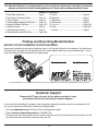
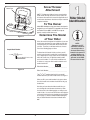
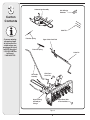
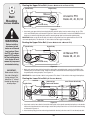
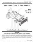
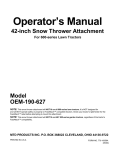
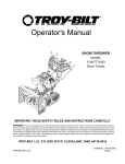
Safety • Assembly • Operation • Tips & Techniques • Maintenance • Troubleshooting • Parts Lists • Warranty
OPERATOR’S MANUAL
Model
OEM-190-032
190-032-101
42-inch Two-Stage Snow Thrower Attachment
For FastAttach™ Compatible Lawn Tractors & Garden Tractors
PRINTED IN U.S.A.
MTD LLC, P.O. BOX 361131 CLEVELAND, OHIO 44136-0019
FORM NO. 769-01933E
4/24/07
This Operator’s Manual is an important part of your snow thrower attachment. It will help you assemble,
prepare and maintain the unit for best performance. Please read and understand what it says.
TABLE OF CONTENTS
1. Rider Model Identification................................. Page 3
2. Snow Thrower Attachment Safety.................... Page 4-5
3. Carton Contents............................................... Page 6-7
4. Assembly Models 600-649 & 800 Series......... Page 8-13
5. Assembly All Model 700 Series........................ Page 14-15
6. Attaching Controls............................................ Page 16
7. Attaching Auger Housing................................. Page 17
8. Routing Upper & Lower Drive Belts.................. Page 18-19
9. Controls............................................................ Page 20
10.Operation......................................................... Page 21
11. Adjustments.................................................... Page 22
12. Maintenance................................................... Page 23
13. Parts List......................................................... Page 24-29
13. Notes.............................................................. Page 30-31
Warranty........................................................... Page 32
Finding and Recording Model Number
BEFORE YOU START ASSEMBLING YOUR NEW EQUIPMENT,
please locate the model plate and copy the information from it in this Operator’s Manual for future reference. The information on
the model plate is very important if you need help from our Customer Support Department or your authorized dealer. You can
locate it by looking on the top rear portion of the auger housing:
Model Number
Serial Number
*Locate the model plate on your snow thrower attachment and copy the information from it in the space provided above for future reference.
Customer Support
Please do NOT return the unit to the retailer from which it was
purchased, without first contacting Customer Support.
If you have difficulty assembling this product or have any questions regarding the controls, operation, or maintenance of this
unit, you can seek help from the experts. Choose from the options below:
• Visit www.mtdproducts.com. Click on the Service & Support menu option.
• Phone a Customer Support Representative at 1-800-800-7310.
• Please have your unit’s model number and serial number ready when you call. See above to locate this information. You will
be asked to enter the serial number in order to process your call.
Snow Thrower
Attachment
Model Plate
.ccotsm 800-800-7310
w td p ro d u
w w .m
MTD LLC
P. O. BOX 361131
44136
CLEVELAND,OH
330-220-4683
NOTE: This Operator’s Manual covers several models.
Snow thrower hook-up instructions vary by model. Not
all features discussed in this manual are applicable to all
snow thrower attachments. Assistance may be needed to
complete instalation.
To The Owner
1
Rider Model
Identification
Model OEM-190-032 two-stage snow thrower attachment is
designed for use on FastAttach™ Compatible Lawn Tractors
and Garden Tractors ONLY. It will NOT fit nor operate
properly or safely on ANY other tractor.
Determine The Model
of Your Rider
Figure 1
Since this manual is designed for installation of your new
snow thrower attachment on several different rider units,
it is important for you to determine which model of rider
you have. Therefore you will know which set of instructions in the following pages to follow.
Sample Model Number
To determine which model of rider you have, you will
need to locate the rider’s model plate, located under the
seat. Simply flip the seat up and locate the model plate,
which will consist of an 11 digit/letter model number
and a serial number. For ease in this installation and
for future use, copy your rider’s model number & serial
number below now:
13AM 7 9 0 G000
Indicates Model Series 700
Rider Model Number:__ __ __ __ __ __ __ __ __ __ __
Figure 2
Rider Serial Number:_________________________
The 5th, 6th & 7th numbers from the left in your model
number determine your rider’s model series. See Figure 2.
When you fill in your model number in the space above,
the actual model series number should fall into the gray
shaded area.
Now that you have determined what model rider you
are attaching this snow thrower attachment to, follow
the instructions in the following pages according to your
model of rider. You can locate which instructions apply to
your model of rider by the gray-shaded area in the border
of each page. For instance, an 809 or 80R would signify
that you should follow the instructions for Model Series
800.
NOTE:
References to LEFT
and RIGHT indicate the
left and right sides of
the tractor when facing
forward in the operator’s
position. Reference to
the FRONT indicates the
grille end; to the REAR,
the rear end of the rider.
3
Undercarriage Assembly
Self-Adhesive
Reflectors
Carton
Contents
Cable Ties
If you are missing
any parts, please
do not contact the
retailer where you
purchased this unit,
call MTD directly at
1-330-220-4MTD or
toll free at
1-800-800-7310.
Extension Spring
Upper Chute Crank Rod
Extension Spring
Cotter Pin
Lift Handle
Assembly
Click Pins &
Clevis Pins
Auger Housing
Assembly w/
Linkage
Spare Shear Bolts
& Hex Lock Nuts
Figure 3
CONTENTS OF CARTON
Before beginning installation, remove all parts from the carton to make sure everything is present. Carton
contents are listed below and shown in Figure 3. Hardware part numbers are shown in parentheses.
• One Auger Housing Assembly w/ Lower V-belt
• One Undercarriage Assembly w/ Upper V-belt
• One Lift Handle Assembly
• One Upper Chute Crank Rod
• Three Cable Ties (725-0157)
• Two Spare Shear Pins (738-04124) & Cotter Pins (714-04040)
• One Cotter Pin (714-0507)
• Two Self-adhesive Reflectors (730-3000)
• Extension Spring (732-04237)
• Extension Spring (732-04237)
• Clevis Pin (711-0332)
• Click Pin (714-0145)
3
Carton
Contents
If you are missing
any parts, please
do not contact the
retailer where you
purchased this unit,
call MTD directly at
1-330-220-4MTD or
toll free at
1-800-800-7310.
4
Assembly
Model Series
600-649 &
All 800 series.
WARNING: Before installing attachment, place tractor on a firm and level surface. Place the
PTO in the disengaged (OFF) position, set the parking brake, shut engine off and remove key
to prevent unintended starting.
NOTE: References to LEFT and RIGHT indicate the left and right sides of the tractor when facing forward in the
operator’s position. Reference to the FRONT indicates the grille end; to the REAR the drawbar end.
IMPORTANT: You must first figure out which model of rider you are attaching this snow thrower to. Refer to Determine
Your Model of Rider on page 3 of this manual to determine what model rider you are attempting to install this attachment
to. Then proceed to the applicable instructions for your model of rider.
Your tractor’s cutting deck, PTO belt and front deck stabilizer bracket must be removed prior to mounting the snow
thrower attachment. Refer to your tractor’s Operator’s Manual for detailed instructions. If your tractor is equipped with
any front-end accessory (i.e. front bumper kit), it must also be removed.
Do you have an Electric PTO or Manual PTO?
If you engage your tractor’s cutting deck by using your left hand to pivot a lever forward, your tractor has a Manual
PTO. If you engage your tractor’s cutting deck by pulling outward on a small knob located on the tractor’s dash, your
tractor has an Electric PTO.
WARNING
Before installing
attachment, place
tractor on a firm
and level surface.
Place the PTO in
the disengaged
(OFF) position, set
the parking brake,
shut engine off and
remove key to prevent
unintended starting.
Mounting the Idler Assembly
Electric PTO Undercarriage
Assembly Setup
Manual PTO Undercarriage
Assembly Setup
1. Attach the PTO cable to the idler bracket, then fit the
cable into the slotted fitting as seen in Figure 4–3.
NOTE: The PTO cable should be hanging down under
you tractor after you removed the mowing deck. You will
need to slide the undercarriage unit under your tractor in
position for which it will be mounted. The slanted side
should be pointed towards the front of your tractor.
Proceed as follows when mounting this snow thrower
attachment to a tractor equipped with a 42, 46, 50 or
54-inch deck with electric PTO:
1. Attach one end of the extension spring (732-0594A)
to the hole in the idler assembly. Mount the opposite
end of the extension spring to the belt keeper pin as
illustrated in Figure 4–1.
2. Refer to Figure 4–4 for correct position.
2. Refer to Figure 4–2 for correct position.
Extension Spring
PTO Cable
Idler Pulley &
Idler Bracket
Idler Pulley &
Idler Bracket
Belt Keeper Pin
Slotted Fitting
Figure 4–1
Figure 4–3
Figure 4–2
Figure 4–4
4
Mounting The
Undercarriage Assembly
1. Remove and retain the four hairpin clips from the
weld pins found on the top side of the undercarriage
assembly. Remove and retain the two clevis pins with
hairpin clips. This hardware is for later installation.
See Figure 4–5.
2. With the undercarriage assembly beneath the tractor,
see figure 4–6, lift the undercarriage assembly up
against the frame of the tractor. The weldpins on the
top of the undercarriage assembly should go through
the aligning holes found along the tractor’s frame.
See Figure 4–7.
Assembly
Figure 4–7
3. Fasten the undercarriage assembly to the frame with
the hairpin clips removed in step 1. See figure 4–8
4. Route the upper drive belt around the engine pulley.
See Figure 4–7.
NOTE: Proceed to the Assembling Controls section of
this manual if you have an Electric PTO.
Model Series
600-649 &
All 800 series.
WARNING
5. Attach the extension spring to the idler pulley. See
figure 4–9. Connect the other end to tractor’s frame rail.
See Figure 4–10.
Figure 4–8
Figure 4–5
Figure 4–9
Figure 4–10
Figure 4–6
Before installing
attachment, place
tractor on a firm
and level surface.
Place the PTO in
the disengaged
(OFF) position, set
the parking brake,
shut engine off and
remove key to prevent
unintended starting.
6
Assembling
Controls
Attaching Chute
Directional Control
Attaching
Lift Handle
1. Attach the chute directional control assembly to the
upper lift link on the left side of the auger housing.
Assemble with two hex screws and washers as
illustrated in Figure 6–1. Secure with two flange nuts.
1. Attach lift handle to lift bracket on the right side of
auger housing assembly with two hex screws and two
flange nuts provided. See Figure 6–3.
2. Fasten the lift cable to the lift handle with two of the
cable ties provided. Pull the cable ties until snug and
trim excess.
1. Secure the upper chute crank rod to the joint block
(A) on the lower chute crank rod with the cotter pin
(B) provided. See Figure 6–2.
Lift Handle
3. Fasten chute tilt cables to chute directional control
with two of the cable ties provided. Pull cable ties
until snug and trim excess.
Upper Lift Link
Chute Directional
Control Assembly
NOTE:
All references to left
or right side of the
snow thrower is
from the operating
position only.
Auger Housing Assembly
Figure 6–3
Mounting Auger Assembly
WARNING: Before installing
attachment, place tractor on a firm
and level surface. Place PTO in the
disengaged (OFF) position, set the
parking brake, shut engine off and remove key to
prevent unintended starting.
Figure 6–1
B
IMPORTANT: If you are installing this snow thrower
attachment on any tractor model with a side discharge
muffler, See Figure 6–4, then the heat shield on the
auger housing must be removed. See figure 6–5. To
A
Figure 6–2
Figure 6–4
Attaching Reflectors
Peel off the backing from each of the reflectors to
expose the adhesive surface. Adhere the reflectors to
the rear of the tractor’s fender (one on the left and one
on the right) so that the reflectors simulate taillights.
7
Mounting
Auger
Housing
Heat Shield
All Models
Figure 6–5
remove the heat shield remove the four lock nuts and
bolts (two on either side of the unit) securing the heat
shield to the lift linkage. See figure 6–5.
IMPORTANT: It will be necessary to have a second
person assist you to complete the following steps.
1. Position the auger housing assembly in front of the tractor
as seen in Figure 6–6. Lay the belt and support tubes on
the installation surface.
Figure 6–7
2. Carefully move the tractor forward (by pushing, NOT
driving it) so that support tubes found on the rear of
the auger housing assembly are positioned between
the tractor’s front tires. Set the parking brake.
3. With the help of an assistant, lift up the auger housing
and move it so that it rests over the shoulder bolts found
on tractor See Figure 6–7.
4. Maneuver the auger housing until the mounting holes
line up. Insert the clevis pins from your hardware pack
and secure with a click pins. See Figure 6–8.
Attaching Support Tubes
1. Secure the left support tube to the front of the
undercarriage assembly with the clevis pin and hairpin
clip removed earlier. See Figure 6–9.
Clevis Pin
Figure 6–8
2. Repeat the previous step on the right side.
Belt
Support Tube
Figure 6–9
Figure 6–6
WARNING
Before installing
attachment, place
tractor on a firm and
level surface. Place
the PTO in the disengaged (OFF) position,
set the parking brake,
shut engine off and
remove key to prevent
unintended starting.
8
Routing the Upper Drive Belt (Tractors Models with an Electric PTO)
Engine Pulley
Spindle Pulley
All electric PTO
Decks 42, 46, 50, 54
Belt
Routing
Various Models
PTO Idler Pulley
Figure 8–1
1. Attach and route upper drive belt around spindle pulley and idler pulley found on undercarriage, electric PTO
clutch and PTO idler pulley as illustrated in Figure 8–1. Make sure that the belt is routed to the INSIDE of the belt
keeper on the undercarriage idler pulley and the remaining keeper pins found around the spindle pulley.
WARNING
Before installing
attachment, place
tractor on a firm and
level surface. Place
the PTO in the disengaged (OFF) position,
set the parking brake,
shut engine off and
remove key to prevent
unintended starting.
IMPORTANT: Make certain that the flat side of the belt is facing outward as it sits against both the electric PTO
clutch and spindle pulley. This allows the “V” side of the belt to ride snugly in both pulleys.
Routing the Upper Drive Belt (Tractor Models with a Manual PTO)
Spindle Pulley
Engine Pulley
All Manual PTO
Decks 38, 42, 46
PTO Idler Pulley
Figure 8–2
IMPORTANT:
Make certain that the
flat side of the belt is
facing outward. This
allows the “V” side of
the belt to ride snugly
in both pulleys.
1. Attach and route the upper drive belt around the engine pulley and spindle pulley, routed to the INSIDE of the
PTO idler pulley on the undercarriage. Make sure the belt is routed inside of the belt keeper pins found around
the spindle pulley and engine pulley. See Figure 8–2.
IMPORTANT: Be certain flat side of belt is facing outward. This allows “V” side of belt to ride snugly in both pulleys.
Routing the Lower Drive Belt (All Tractors Models)
Left Side
Spindle Pulley
Undercarriage
Double-Idler Bracket
Snow Thrower Drive Pulley
Right Side
Figure 8–3
1. Attach and route the lower drive belt around the lower pulley on the spindle assembly, both pulleys on the doubleidler bracket found beneath the undercarriage, and the drive pulley found on the rear of the snow thrower housing
as illustrated in Figure 8–3.
2. Attach tension spring (found on undercarriage double-idler bracket) to the hex screw if it is not already attached.
10
WARNING: Be familiar with all controls
and their proper operation. Know how
to stop the machine and disengage
them quickly.
Engaging the Augers
and Impeller
Power to the snow thrower attachment is activated by
engaging the tractor’s PTO.
1. Place the tractor’s throttle control in the FAST (rabbit)
position and allow it to remain there for efficient snow
removal.
2. Move the PTO knob or PTO lever (on tractor’s so
equipped) into the “ON” position to engage the augers
and impeller.
3. Move the PTO knob or PTO lever (on tractor’s so
equipped) into the “OFF” position to disengage the
augers and impeller.
NOTE: The PTO knob (on units so equipped) cannot be
in the engaged (ON) position when the tractor is driving
in the reverse direction. The PTO knob must be in the
disengaged (OFF) position when the shift lever is placed
in REVERSE or the electric PTO clutch will automatically
shut off.
Refer to your tractor’s Operator’s Manual for more
information regarding your tractor’s PTO and safety
interlock system.
Trigger Control
Lift Handle
The lift handle is located on the right side of tractor and
is used to raise and lower snow thrower attachment.
1. To raise snow thrower attachment off of the ground,
pull rearward and down on the lift handle until
you feel the lift latch on the right side of the snow
thrower engage, locking the snow thrower in a raised
position See Figure 9–1.
9
Controls
2. To lower the snow thrower, push downward on the
lift handle until there is enough slack in the lift cable
so that you may squeeze the trigger control. With
the trigger control squeezed, gently allow the snow
thrower to lower until it reaches the ground.
Chute Directional
Control
The chute directional control assembly is found on
the left side of the tractor and includes both the chute
tilt lever as well as the chute crank. Both affect the
direction that the discharged snow is thrown.
To pivot upper section of discharge chute, affecting the
distance and angle which the snow is thrown, move
the chute tilt lever forward or rearward into a desired
position.
WARNING
Be familiar with all
controls and their
proper operation.
Know how to stop
the machine and
disengage them
quickly.
The direction which snow is thrown can be changed
by rotating the discharge chute with the chute crank.
Turn the chute crank clockwise to rotate the chute and
discharge snow to the left. Crank it counterclockwise to
rotate the chute and discharge snow to the right.
Chute Directional Control
Lift Handle
Figure 9–1
11
NOTE:
The PTO knob (on
units so equipped)
cannot be in the
engaged (ON) position
when the tractor is
driving in the reverse
direction. The PTO
knob must be in the
disengaged (OFF)
position when the
shift lever is placed
in REVERSE or the
electric PTO clutch
will automatically
shut off.
10
Operation
OPERATION
15.If the augers become jammed with a chunk of ice or a
foreign object, move the PTO into the disengaged (OFF)
position immediately and turn off the tractor’s engine
and remove the ignition key. Examine the auger area
thoroughly for damage and do NOT operate the snow
thrower attachment until any damage is repaired.
WARNING: Read, understand, and
follow all instructions and warnings
on the tractor, attachment, and in the
Operator’s Manuals before operating.
Your snow thrower attachment is capable of displacing
snow and clearing a path a width of 42 inches.
IMPORTANT: The augers are secured to the spiral
shaft with two shear bolts and hex lock nuts. If you hit
a hard foreign object or an ice jam, the snow thrower is
designed so that the bolts may shear. Two replacement
shear bolts and hex lock nuts are provided for your
convenience. Store in a safe place until needed. NEVER
replace the auger shear bolts with standard hex bolts.
Any damage to the auger gearbox or other components
as a result of doing so will NOT be covered by your snow
thrower’s warranty.
Observe the following operating instructions for efficient
snow removal.
1. Become familiar with and comfortable using all of
your tractor’s controls as instructed in your tractor’s
Operator’s Manual before operating it with the snow
thrower attachment.
WARNING
Read, understand,
and follow all
instructions and
warnings on the
tractor, attachment,
and in the Operator’s
Manuals before
operating.
IMPORTANT:
The augers are secured
to the spiral shaft with
two shear bolts and hex
lock nuts. If you hit a
hard foreign object or
an ice jam, the snow
thrower is designed
so that the bolts may
shear. Two replacement
shear bolts and hex
lock nuts are provided
for your convenience.
Store in a safe place
until needed. NEVER
replace the auger shear
bolts with standard hex
bolts. Any damage to
the auger gearbox or
other components as a
result of doing so
will NOT be covered
by your snow
thrower’s warranty.
2. Make certain the correct weight (and volume) of
motor oil in is your tractor’s engine as instructed in
the engine Owner’s Guide packed with the tractor’s
Operator’s Manual.
16.Whenever possible, discharge snow downwind.
17. Do NOT attempt to remove ice or hard-packed frozen snow.
18.When the tractor (with the snow thrower attachment
mounted) is not in service, use the lift lever to lower
the auger housing assembly to the ground to relieve
strain on the tractor’s front end between uses.
3. Always operate the snow thrower with the tractor’s
engine at maximum RPM (full throttle).
4. NEVER override any safety features on either your
tractor or the snow thrower attachment.
19.Always use tire chains and rear wheel weights on
your tractor where extra traction is needed. Refer to
the table to the right to determine which kits will fit
your tractor (tire dimensions are can be found on the
sidewalls of your tractor’s tires).
5. Make certain that all nuts, bolts, and hardware are
fastened securely and tight on both the tractor and
the snow thrower attachment prior to use.
6. Make certain snow thrower is assembled
properly and mounted to the tractor as instructed
in this manual.
20.Use drift cutters to aid in displacing snow through
deep, drifted areas.
8. Test all controls (tractor PTO, snow thrower lift
handle, chute tilt lever & chute crank) for smooth
operation prior to operating snow thrower in snow.
Tire Chain Kit Number
Garden Tractors
9. Make all adjustments (i.e. skid shoes, lift latch)
before operating your snow thrower attachment.
Follow instructions in the Adjustments section of this
manual when doing so.
23” x 9.5” tires
22” x 7.5” tires
OEM-190-964
OEM-190-974
Lawn Tractors
10.Engage the tractor’s PTO to activate power to the
augers and impeller BEFORE driving the tractor
forward and into snow.
20” x 10.0” tires
20” x 8.0” tires
18” x 9.5” tires
18” x 8.5” tires
18” x 6.5” tires
11.Keep your tractor’s ground-speed slow. The slower
your tractor is traveling, the more effectively the
snow thrower attachment can displace snow.
OEM-190-916
OEM-190-658
OEM-190-657
OEM-190-754
OEM-190-664
12.Adjust ground speed for snow conditions and
become familiar with different snow applications.
Your snow thrower attachment will operate differently
in wet heavy snow than it will it light, fluffy snow.
Weight Kit Number
13.Overlap a previously cleared path when necessary
(deep snow) so as not to overload the auger housing
with snow.
Drift Cutter Kit Number
14.NEVER drive the tractor into a snow bank. The
snow thrower attachment is not a dozer plow. The lift
linkage and/or the snow thrower drive system can
be damaged as a result of “plowing” with the snow
thrower attachment.
All Garden TractorsOEM-190-784
All Lawn Tractors OEM-190-215
All Tractors
OEM-390-679
NOTE: None of the kits in the table are included as
standard equipment with snow thrower attachment
OEM-190-032. Call our Customer Support Department
as instructed on page 2 of this manual for availability and
information regarding these kits.
12
Making Adjustments
Lift Cable
Hex Nuts
WARNING: Never attempt to make any
adjustments while the engine is running,
except where specified in the Operator’s
Manual. Place tractor on a firm and
level surface. Place the PTO in the disengaged (OFF)
position, set the parking brake, shut engine off, and
remove key to prevent unintended starting.
11
Adjustments
Lift Adjustment
If the lift index rod doesn’t latch securely or the pivot
release has too much slack in it, an adjustment can be
made as follows:
1. Loosen the upper hex nut a few turns, then tighten the
lower hex nut to shorten the cable length. See Figure 11–1.
Lift Index Rod
2. Loosen the lower hex nut a few turns, then tighten the
upper hex nut to lengthen the cable. See Figure 11–1.
WARNING
Figure 11–1
Lower Chute Crank
Support Bracket Adjustment
If the spiral at the base of the lower chute crank isn’t fully
engaging with the notches in the lower chute assembly,
the support bracket can be adjusted inward or outward as
follows:
1. Loosen, but do NOT remove the two hex nuts which
secure the support bracket to the snow thrower
housing. See Figure 11–2.
Spiral
2. Adjust the support bracket inward or outward so that
the spiral is fully engaged in the notches on the chute
before retightening the hex nuts.
Hex Nuts
Skid Shoe Adjustment
The space between the shave plate and the ground can
be adjusted by repositioning the skid shoes found on
either side of the snow thrower’s auger housing. For close
snow removal, place skid shoes in the low position. Use
a middle or high position when the area to be cleared is
uneven.
IMPORTANT: It is NOT recommended that this snow
thrower be operated on a gravel surface, as loose stones
can be easily picked up and thrown by the machine. If
you must operate on a gravel surface, ALWAYS adjust the
skid shoes into the HIGH position to allow the shave plate
maximum clearance.
Support
Bracket
Figure 11–2
Adjust skid shoes as follows:
1. Loosen, but do NOT remove, the three hex nuts which
fasten the skid shoe to the auger housing.
See Figure 11–3.
Skid Shoe
2. Raise or lower the skid shoe to desired position.
NOTE: Make certain the entire base of both skid shoes
are against the ground to avoid uneven wear on the skid
shoes. When one side does wear out, the skid shoes are
reversible.
Hex Nut
3. Retighten the hex nuts loosened earlier.
4. Repeat this adjustment on the skid shoe found on the
opposite side of the snow thrower.
Figure 11–3
13
Never attempt
to make any
adjustments while
the engine is running,
except where
specified in the
Operator’s Manual.
Place tractor on a
firm and level
surface. Place
the PTO in the
disengaged (OFF)
position, set the
parking brake,
shut engine off,
and remove key
to prevent
unintended starting.
12
Maintenance
Maintenance
Lube Spiral
and Chute Base
WARNING: Before lubricating, repairing, or inspecting, place tractor on a
firm and level surface. Place the PTO
in the disengaged (OFF) position, set
the parking brake, shut engine off, and remove key
to prevent unintended starting.
Lubrication of
Chute Directional Control
The spiral on the end of the lower chute crank, the base
of the discharge chute itself and the joint blocks which
connect the lower and upper chute cranks should be
lubed with multi-purpose automotive grease once a
season. See Figure 12–1.
Joint Block
WARNING
Before lubricating,
repairing, or
inspecting, place
tractor on a firm
and level surface.
Place the PTO in
the disengaged
(OFF) position, set
the parking brake,
shut engine off, and
remove key to prevent
unintended starting.
Figure 12–1
Auger Shaft
1. At least once a season, remove the shear bolts on
the auger shaft. Oil or spray lubricant inside and
on the plastic bearings on the shaft and near the
holes where the shear bolts were removed before
reattaching them. See Figure 12–2.
Shear Pin
Spacers
Figure 12–2
14
Bearing
AA
19
BB
6
Part List:
5
Snow
Thrower
Attachment
14
7
4
16
9
11
13
1
18
12
17
8
2
13
3
11
10
For parts and/or
accessories
please call
1-800-800-7310, or
1-330-220-4683.
www.mtdproducts.com
15
REF
NO.
PART
NUMBER
DESCRIPTION
REF
NO.
PART
NUMBER
DESCRIPTION
1
736-3072
Flat Washer, .38 x .93 x .11
11
741-0919
Ball Bearing
2
710-0151
Hex Cap Screw, 3/8-24 x 2
12
750-1096
Spacer
3
710-0521
Hex Cap Screw, 3/8-16 x 3
13
619-0044
Deck Spindle Housing
4
711-0242
Spacer
14
756-0999
Deck Pulley 7”
5
712-0241
Hex Nut, 3/8-24
15
756-1173
Pulley 3.75”
6
732-0978
Extension Spring, .620 x 5.62
16
738-0976
Spindle Shaft
7
736-0169
Lock Washer, 3/8
17
756-0627D
Idler Pulley 3.50 dia.
8
756-0487
Idler pulley, 4” Diameter
18
738-0347
Shoulder Spacer, .625 x .169
9
784-5727
Idler Pivot Arm
19
712-0417
Flange Nut 5/8-18
10
712-0417
Flange Nut 5/8-18
15
NOTE:
For painted parts, please
refer to the list of color
codes below. Please add
the applicable color code,
wherever needed, to the
part number to order a
replacement part.
For instance, if a part
numbered 700-xxxx is
painted powder black, the
part number to order would
be 700-xxxx-0637.
Yardman Green - 0665
Black - 0637
1
6
16
2
52
5
8
17
55
4
3
9
10
60
62
20
7
74
4
57
58
12
4
54
61
18
11
AA
4
4
15
29
C
75
14
22
B
26
19
13
97
59
53
50
21
51
67
67
98
22
56
91
89
99
4
79
78
82
42
28
33
93
4
85
87
48
88
39
86
76
95
24
A
35
80
53
38
43
33
65
36
47
40
B
77
32
32
81
74
BB
34
39
31
A
55
46
64
4
63
4
C
67
49
A
65
25
x
23 29
90
92
41
72
A
81
91
70
69
71
45
30
4
67
68
66
44
73
4
67
65
37
16
27
REF
NO.
1
2
3
4
5
6
7
8
9
10
11
12
13
14
15
16
17
18
19
20
21
22
23
24
25
26
27
28
29
30
31
32
33
34
35
36
37
38
39
40
41
42
43
44
45
46
47
48
49
50
51
PART No.
720-0232
784-5604
731-1313C
712-04063
603-0302
710-0262
736-0451
741-0475
735-0234
747-0697
736-0242
750-04467
714-0507
784-5149
747-1201
746-1108
746-1109
715-0138
720-0201A
726-0100
747-04400
715-0129
611-0132A
783-0880C
783-0879C
683-04150
710-0805
710-0964A
710-3008
711-0332
712-0386A
712-3000
712-3022
714-0470
714-0474
716-0102
784-0402
736-0272
736-0366
736-0452
783-1014A
738-0234
741-0170
756-1181A
747-1192
783-0876
783-0877
783-0878
783-1274B
790-00110
710-1268
DESCRIPTION
REF
NO.
Knob
Chute Tilt Handle
Chute Tilt Cable Guide
Nylon Hex Lock Nut, 5/16-18
Chute Tilt Bracket Assembly
Carriage Bolt, 5/16-18 x 1.5
Saddle Washer, .32 x .93
Plastic Bushing
Rubber Grommet , .44 x .94 x .5
Eye Bolt
Bell Washer, .340 x .872
Support Chute Tube
Cotter Pin, 3/32 x .75
Joint Block Assembly
Chute Crank Rod, .375 x 33
Chute Cable, 62”
Chute Cable w/ Clip, 62”
Rolled Pin, 1/8 x .63
Crank Knob
Push Cap, 3/8 ID
Rod, .375 x 11.375
Spirol Pin, .125 x .82
Rod Assembly
RH Support Plate Assembly
LH Support Plate Assembly
Lift Bracket Assembly
Hex Cap Screw, 5/16-18 x 1.50
Hex Cap Screw, 5/8-18 x 1.31
Hex Cap Screw, 5/16-18 x .75
Clevis Pin, .5 x .78
Slotted Hex Nut, 5/8-18
Hex Lock Nut, 3/8-16
Hex Lock Nut, 1/2-13
Cotter Pin, 1/8 x 1.25
Cotter Pin, .125 x .75
Snap Ring
Skid Plate
Flat Washer, .51 x 1.0 x .060
Flat Washer, .64 x 1.12 x .125
Bell Washer, .396 x 1.14 x .095
Drive Mounting Bracket
Shoulder Screw, .5 x .29, 3/8-16
Flange Bearing w/ Flats
Drive Pulley, 7”
Rod, 1/2 x 11.55
Link, 5.875
Link, 15.4
Link, 13.35
Heat Shield
Snow Thrower Lift Bracket
Hex Index Washer Screw #10-16
17
PART No.
DESCRIPTION
52
53
54
55
56
57
58
59
60
61
62
63
64
65
66
67
68
69
70
710-3143
710-3180
715-0114
720-0274
725-0157
732-0306
736-0140
736-0400
746-1103A
747-1203
750-1221
05931A
703-2736
710-0514
710-3251
712-04065
714-0122
714-0126
717-1714A
Pan Phillips Screw, #10-24 x .75
Hex Cap Screw, 5/16-18 x 1.75
Heavy Duty Spirol Pin, 1/4 x 1.5
Handle Grip
Cable Tie
Compression Spring
Flat Washer, .385 x .62 x .063
Flat Washer, .194 x .62 x .063
Lift Cable, 42” w/ Trigger Control
Lift Index Rod
Lift Handle Tube
Bearing Housing, 1.85 ID
Belt Cover
Hex Cap Screw, 3/8-16 x 1.0
Socket Head Cap Screw
Flange Lock Nut, 3/8-16
Square Key, 3/16 x .75
Hi-pro Key, 3/16 x .75
Right Angle Drive
71
72
73
74
718-0691
741-0309
747-1257
712-3010
Coupling
Flange Ball Bearing, .75 x 1.85
Belt Keeper Rod
Flange Nut, 5/16
75
618-0411
Spindle Assembly (Incl. 38-44)
76
683-04210
Pulley Mounting Bracket
77
684-0149
Double Idler Bracket Assembly
78
710-0347
Hex Cap Screw, 3/8-16 x 1.75
79
710-04511
Pin 5/16-18
80
710-0260A
Carriage Bolt, 5/16-18 x .62
81
711-0310
Clevis Pin, .5 x 1.18
82
711-1000
Belt Keeper Pin
83
712-04064
Nylon Hex Lock Nut, 1/4-20
84
712-04100
Wing Nut 5/16-18
85
714-0145
Click Pin, .092 x 1.64
86
714-0147
Internal Cotter Pin, .125 x 1.75
87
730-3000
Reflector
88
732-04237
Extension Spring .50 x 12.00
89
732-0594A
Extension Spring .91 x 7.33
90
736-0192
Flat Washer, .531 x .93 x .09
91
736-3072
Flat Washer, .38 x .93 x .11
92
738-0145
Shoulder Screw, 3/8-16
93
738-0347
Shoulder Spacer, .625 x .169
94
749-1103
LH Support Tube
95
749-1104
RH Support Tube
96
754-0125A
V-Belt
97
754-0498
V-Belt
98
756-0627D
Idler Pulley 3.50 dia.
99
783-1291
Idler Bracket
13
Part List:
Snow
Thrower
Attachment
For parts and/or
accessories
please call
1-800-800-7310, or
1-330-220-4683.
www.mtdproducts.com
56
52
61
58
55
47
15
46
52
53
51
45
49
60
59
52
3
43
42
54
50
62
44
16
48
52
57
8
A
9
51
2
16
9
63
9
19
10
20
15
16
7
41
6
23
16
38
25
40
35
39
24
1
5
34
37
36
32
A
7
26
28
64
31
40
29
33
30
27
21
14
16
65
11
18
66
18
4
21
17
22
13
12
REF
NO.
PART
NUMBER
DESCRIPTION
REF
NO.
PART
NUMBER
DESCRIPTION
1
618-04315
Auger Gear Box (Incl. Ref. 23-41)
34
721-0327
Grease Seal
2
684-0158
Impeller Assembly, 12”
35
736-0351
Flat Washer, .76 x 1.5 x .030
3
684-0148
Housing Assembly
36
736-0369
Flat Washer, .508 x 1.0 x .020
4
703-2734
Housing Brace Bracket
37
736-0617
Thrust Washer, .75 x 1.25 x .0615
5
684-04163
LH Spiral Auger
38
741-0150
Thrust Bearing, .75 x 1.25 x .078
6
684-04164
RH Spiral Auger
39
748-0108
Flange Bearing, .503 x .75
7
710-0157
Hex Cap Screw, 5/16-24 x .75
40
741-0700
Flange Bearing, .75 x 1.0 x .59
8
710-0260A
Carriage Bolt, 5/16-18 x .62
41
721-0179
Grease Seal
9
710-0276
Splined Carriage Screw
42
684-0061
Chute Crank Assembly
10
710-0726
Self Tapping Screw
43
703-2735A
Chute Crank Bracket
11
714-04040
Bow-Tie Cotter Pin
44
705-5226
Chute Reinforcer
12
712-3010
Hex Nut, 5/16-18
45
710-0276
Splined Carriage Screw
13
712-3057
Hex Nut, 5/16-24
46
710-0262
Carriage Bolt, 5/16-18 x 1.5
14
715-0114
Spirol Pin, 1/4 x 1-1/2
47
710-04071
Carriage Screw, 5/16-18 x 1.0
15
736-0231
Flat Washer, .344 x 1.125 x .12
48
710-0703
Screw, 1/4-20 x .75
16
736-0242
Bell Washer, .340 x .872
49
710-0896
Hex Index Washer Screw
17
741-0245
Hex Flange Bearing, .75 ID
50
710-3015
Hex Cap Screw, 1/4-20 x .75
18
741-0493A
Flange Bushing, .80 x .91
51
712-04064
Nylon Hex Lock Nut, 1/4-20
19
784-0396A
Skid Plate Bracket, 42”
52
712-04063
Nylon Hex Lock Nut, 5/16-18
20
784-5038B
Slide Shoe
53
715-0129
Spirol Pin, .125 x .82
21
711-0469
Spacer, .75 x .125 x .5
54
731-0851A
Chute Flange Keeper
22
784-5618
Hex Bearing Housing, 1.0
55
731-1300B
Lower Chute
23
618-0123A
RH Reducer Housing
56
731-1320
Upper Chute
24
618-0124A
LH Reducer Housing
57
731-1379C
Adapter Chute
25
703-2733A
Housing Brace Plate
58
731-1313C
Chute Tilt Cable Guide
26
710-0642
Self Tapping Screw, 1/4-20 x .75
59
741-0475
Plastic Bushing
27
711-04468
Spiral Axle, 41.5”
60
784-5149
Joint Block Assembly
28
714-0161
Hi-Pro Key, 3/16 x 5/8
61
784-5594
Cable Bracket
29
715-0143
Spring Spirol Pin, .25 x 1.25
62
784-5647
Chute Crank Bracket
30
717-0528A
Worm Gear, 20-tooth
63
712-3004A
Flange Lock Nut, 5/16-18
31
717-3320
Worm Shaft
64
731-04870
Spacer 1.25 x .75 x 1.00
32
718-0513
Thrust Collar
65
731-1086A
Sleeve .758 x 1.00 x 2.70
33
721-0325
Grease Plug
66
738-04124
Shear Pin, .25 x 1.50
19
13
Part List:
Snow
Thrower
Attachment
For parts and/or
accessories
please call
1-800-800-7310, or
1-330-220-4683.
www.mtdproducts.com
NOTE:
For painted parts, please
refer to the list of color
codes below. Please add
the applicable color code,
wherever needed, to the
part number to order a
replacement part.
For instance, if a part
numbered 700-xxxx is
painted powder black, the
part number to order would
be 700-xxxx-0637.
Yardman Green - 0665
Black - 0637