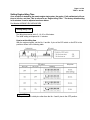
1
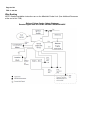
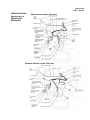
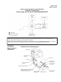
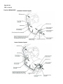
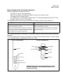
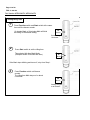
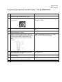
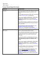
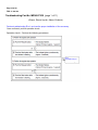
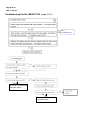
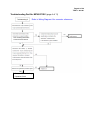
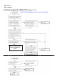
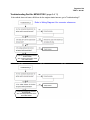
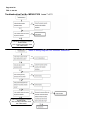
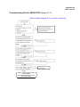
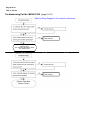
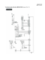
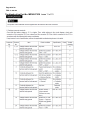
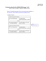
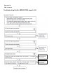
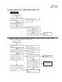
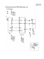
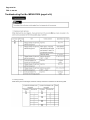
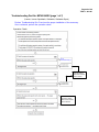
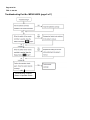
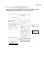
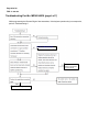
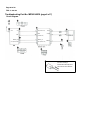
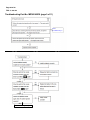
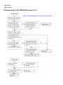
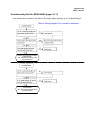
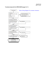
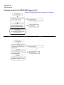
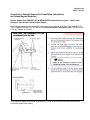
Page 1 of 54 Technical Service Bulletin SUBJECT: ACCESSORY REMOTE ENGINE START No: TSB−11−66−001 DATE: October, 2011 MODEL: See below CIRCULATE TO: [ ] GENERAL MANAGER [ X ] PARTS MANAGER [ X ] TECHNICIAN [ X ] SERVICE ADVISOR [ X ] SERVICE MANAGER [ ] WARRANTY PROCESSOR [ ] SALES MANAGER PURPOSE This TSB contains technical information and troubleshooting for the accessory Remote Engine Start system for affected vehicles. AFFECTED VEHICLES The following vehicles except manual transmission models: 2009−2011 Endeavor 2010−2012 Eclipse/Eclipse Spyder 2009.5−2012 Galant 2009−2011 Lancer 2010−2011 Lancer Sportback 2009−2012 Outlander 2011−2012 Outlander Sport TABLE OF CONTENTS Remote Engine Start Kits and Transmitters Wire Routing Transmitter Operation Setting Engine Idle Time Programming the RKE System Programming the KOS System Programming the Keyless Push Start System Common Remote Engine Start Issues Troubleshooting Part No. MZ360271EX Troubleshooting Part No. MZ360272EX Troubleshooting Part No. MZ360340EX Troubleshooting Part No. MZ360360EX Correction to Eclipse/Spyder/Endeavor Installation Instructions Additional Resources OVERVIEW Remote engine start allows starting the engine from a distance, before entering the vehicle. Use the Remote Engine Start transmitter to start or stop the engine. The engine will idle for a preset period of time (5, 10, 20 or 30 minutes), or when specific conditions are detected. The factory default is 10 minutes. For remote starting to occur, the following requirements must be met: D Transmission in P (Park) D All doors closed, including liftgate/trunk. (Door locking/unlocking is not affected by remote start.) D Engine hood closed Copyright 2011, Mitsubishi Motors North America, Inc. (3789) The information contained in this bulletin is subject to change. For the latest version of this document, go to the Mitsubishi Dealer Link, MEDIC, or the Mitsubishi Service Information website (www.mitsubishitechinfo.com). Page 2 of 54 TSB−11−66−001 D Key removed from ignition (for KOS equipped vehicles, the ignition switch is in the LOCK position) D Transmitter within approximately 150 feet of the vehicle After the engine is started with the Remote Engine Start transmitter, it will stop if any of the following conditions are detected: D A door (or liftgate/trunk) is opened D The accelerator pedal is pressed (except Endeavor, Galant and Eclipse models) D The engine hood is opened. D The key is inserted into the ignition switch (for KOS vehicles, the ignition switch is turned from the LOCK position). Remote Engine Start Kits and Transmitters Model Affected Vehicles Part Number 2009.5 − 2012 Galant VIN 9E024751 and above MZ360271EX / MZ360360EX * 2010 Eclipse/Eclipse Spyder From start of 2010MY production MZ360271EX / MZ360360EX * 2009 − 2011 Endeavor From start of 2009MY production MZ360271EX / MZ360360EX * 2009 Lancer From start of 2009MY production MZ360272EX 2010 − 2011 Lancer After June 1, 2008 production MZ360340EX 2010 − 2011 Lancer Sportback From start of 2010MY production MZ360340EX 2009 Outlander From start of 2009MY production MZ360272EX 2010 − 2012 Outlander From start of 2010MY production MZ360340EX 2011 − 2012 Outlander Sport From start of 2011MY production MZ360340EX * MZ360360EX is a mid-year replacement of the MZ360271EX remote engine start kit. Older transmitter Part number MZ360300EX − Provided with MZ360271EX and MZ360272EX kits Newer transmitter Part number MZ360361EX − Provided with MZ360360EX and MZ360340EX kits This may also be used as a replacement transmitter for the MZ360271EX or MZ360272EX kit. (See Replacement Transmitters below.) Page 3 of 54 TSB−11−66−001 Replacement Transmitters: When ordering a replacement for the MZ360271EX or MZ360272EX original transmitter, a newer one, MZ360361EX will be provided. The features on the new transmitter will be limited to the same functions as the older one that was provided in the kit. To program the replacement transmitter for MZ260271EX, see MZ360360EX Programming. To program the replacement transmitter for MZ360272EX, see MZ360340EX Programming. The procedure for setting the engine idling time must follow the procedure for MZ360272EX. For safety reasons, only one transmitter can be programmed to the system at a time. Page 4 of 54 TSB−11−66−001 Wire Routing NOTE: Detailed installation instructions are on the Mitsubishi Dealer Link. (See Additional Resources at the end of this TSB). Eclipse, Eclipse Spyder, Galant, Endeavor Remote Engine Start Kit Part No. MZ360271EX/MZ360360EX Page 5 of 54 TSB−11−66−001 WIRING DIAGRAM A Galant Harness Layout (Top View) Remote Start p/n: MZ360271EX & MZ360360EX Endeavor Harness Layout (Top View) Page 6 of 54 TSB−11−66−001 WIRING DIAGRAM A (continued) Remote Start p/n: MZ360271EX & MZ360360EX Eclipse/Eclipse Spyder Harness Layout (Top View) Page 7 of 54 TSB−11−66−001 Lancer, Lancer Sportback, Lancer Evolution, Outlander, Outlander Sport Remote Engine Start Kit Part No. MZ360340EX/MZ360272EX Note: Detailed installation instructions can be found on the MITSUBISHI DEALER LINK. (See Additional Resources at the end of this TSB for details on accessing these instructions). Note: A hood switch (MZ360316EX) will have to be installed on Lancer/Lancer Sportback produced before 1/31/2010 and 2010-2011 Lancer DE. Hood switch installation instructions are on the MITSUBISHI DEALER LINK. DIAGRAM B Remote Start p/n: MZ360340EX Outlander/Lancer Harness Layout Page 8 of 54 TSB−11−66−001 Part No. MZ360272EX Outlander Harness Layout Lancer Harness Layout Page 9 of 54 TSB−11−66−001 Remote Engine Start Transmitter Operation Before operating the transmitter, verify that: The shifter is in the “P” (Parking) position. All doors (including the rear gate and spare tire carrier) are securely closed. The engine hood is securely closed The vehicle key is removed from the ignition switch. For vehicles equipped with the F.A.S.T. Key, the ignition switch is on the LOCK position. The transmitter will not start the engine unless all of the above conditions are properly set. Starting Engine Stopping Engine 1. Push the request/function button. The indicator will blink for approximately 2 seconds. 2. Push the start button while the indicator is blinking. The engine starting signal will be transmitted when the indicat or stays on for 3 seconds. When the engine starts, the haz ard warning light on the vehicle will flash once. 1. Push the request/function button. The indicator will blink for approximately 2 seconds. 2. Push the stop button while the indicator is blinking. The engine stop signal will be transmitted when the indicator stays on for 3 seconds. NOTE: Extend the antenna if necessary. The transmitter signal will reach further when the antenna is extended. The remote engine starter will stop running after 10 minutes (factory default setting). The time setting can be changed. Refer to “Setting Engine Idle Time” below. Part No. MZ360300EX Part No. MZ360361EX Switch Lock SW Indicator Antenna Switch Unlock SW Function SW Start SW Stop SW Indicator Start button Key ring Stop button Request button Additional information on these transmitters is on the Mitsubishi Dealer Link. (See Additional Resources at the end of this TSB). Page 10 of 54 TSB−11−66−001 Switch Lock The remote for the MZ360360EX and MZ360340EX accessory parts have a switch lock function. Details are described below: Page 11 of 54 TSB−11−66−001 Setting Engine Idling Time Once a vehicle is started by the remote engine start system, the engine, if left undisturbed, will continue to idle for a set time. This is referred to as “Engine Idling Time.” The factory default setting is 10 minutes. It can be adjusted as shown below. Part Number MZ360271EX/ MZ360272EX Setting Idling Time The idling time can be set to 5, 10, 20 or 30 minutes. The initial setting at shipment is 10 minutes. How to set the idling time With the engine stopped, set the No. 2 and No. 3 pins of the DIP switch on the ECU to the positions shown in the following table. ! CAUTION Always set the DIP switch pins other than the No. 2 and 3 pins to the OFF position. Page 12 of 54 TSB−11−66−001 Part Number MZ360360EX/ MZ360340EX Setting Idling Time 1 Press Function switch and Start switch at the same time until the buzzer sounds. 10 minutes Mark or 30 minutes Mark will blink according to the default setting. 10 MINUTES Preset setting is 10 minutes 2 Press Start switch to set the idling time. The selected idle time Mark blinks. (Example shows 30 minutes idle time) 30 MINUTES If the Mark stops blinking and turns off, retry from Step 1. 3 Press Function switch until buzzer sounds. The idling time Mark stays on for about 2 seconds. 30 MINUTES Setting changed to 30 minutes Page 13 of 54 TSB−11−66−001 Programming the RKE System No. MZ360271EX MZ360272EX MZ360340EX MZ360360EX Response 1 Close all doors and hatch, but open hood. Turn off ignition and remove key. Close all doors, hood and hatch. Turn off ignition and remove key. Close all doors, hood and hatch. Turn off ignition and remove key. Close all doors and N/A hatch, but open hood. Turn off ignition and remove key. 2 Insert ignition key. Turn the key to ACC position. Turn key back to Lock (OFF) 5 times within 10 seconds. Then remove the key from the ignition. ECU beeps once. For MZ360340EX: Insert ignition key. Turn key from Lock (OFF) to ACC. Wait 3 to 5 seconds. Return key to Lock (OFF). Repeat 4 times within 10 seconds. 3 Within 10 seconds after the beep sounds, press the 3 buttons on the transmitter all at once and hold for 2 seconds or longer. HINT: It can be done in the following order: press and hold Start, add Stop, add Request. Buzzer on transmitter sounds once and its indicator light will start blinking. Buzzer on transWithin 5 seconds after the beep sounds, mitter sounds once press the 3 buttons on the transmitter all and its “Start” and “Stop” lights will at once and hold for 1 second or more. begin blinking. HINT: It can be done in the following order: press and hold Start, then add Stop, then add Function. 4 While indicator lights are blinking, insert the ignition key and turn to ACC, then back to Lock (OFF). Then remove the key. While the “Start” and “Stop” lights are blinking, insert the ignition key and turn to ACC, then back to Lock (OFF). Then remove the key. ECU beeps once. 5 Perform the engine stop operation by the remote controller. HINT: Press the “Request” button, then press the “Stop” button and hold both for 1 second or longer. Perform the engine stop operation by the remote controller. Hint: Press the “Stop” button and hold for 1 second or more. ECU beeps twice. 6 N/A Within 10 seconds after the ECU beep, press the unlock button on the vehicle remote 3 times. Press unlock button 3 times 7 Remote Engine Start registration is completed. N/A Door locks automatically lock and unlock. Then several seconds later they lock and unlock again. Page 14 of 54 TSB−11−66−001 Programming the KOS System No. MZ360272EX MZ360340EX Response 1 Close all doors, hood and hatch. Get into the vehicle and make sure the ignition is OFF. Remove the knob cap. Insert emergency key. N/A 2 Turn emergency key to ACC position, then back to Lock (OFF) 5 times within 10 seconds. Then remove the key. ECU beeps once. 3 Within 10 seconds after the beep sounds, press the 3 buttons on the transmitter all at once and hold for 2 seconds or longer. HINT: It can be done in the following order: press and hold Start, add Stop, add Request. Turn emergency key from Lock (OFF) to ACC. Wait 3 to 5 seconds. Return key to Lock (OFF). Repeat 4 times within 10 seconds. Buzzer on transmitter sounds once and its indicator light will start blinking. Within 5 seconds of finishing Step 2, press the 3 buttons on the transmitter all at once and hold for 1 second or more. HINT: It can be done in the following order: press and hold Start, then add Stop, then add Function. Buzzer on transmitter sounds once and its “Start” and “Stop” lights will begin blinking. 4 While indicator lights are blinking, insert the ignition key and turn to ACC, then back to Lock (OFF). Then remove the key. While the “Start” and “Stop” lights ECU beeps once. are blinking, insert the ignition key and turn to ACC, then back to Lock (OFF). Remove the key. 5 Perform the engine stop operation by the remote controller. HINT: Press the “Request” button, then press the “Stop” button, and hold both for 1 second or longer. Perform the engine stop operation by the remote controller. HINT: Press the “Stop” button and hold for 1 second or longer. 6 Within 10 seconds after the ECU beep, press the unlock button on the vehicle remote 3 times. Press the unlock button on the KOS key 3 times 7 Remote Engine Start registration is complete. ECU beeps twice. Door locks automatically lock and unlock. Then several seconds later they lock and unlock again. Page 15 of 54 TSB−11−66−001 Programming the Keyless Push Start System − Part No. MZ360340EX No. Action Response 1 Close all doors, hood, and hatch. Get into the vehicle and make sure the ignition is OFF. N/A 2 Press the Engine Start button once, then wait for 3 to 5 seconds. The indicator light on the transmitter switch changes to orange. 3 Press the Engine Start button twice. The indicator light on the transmitter switch turns off. 4 Within 10 seconds of the last step, press the Engine Start button 12 times. ECU beeps once. 5 Within 5 seconds of finishing Step 4, press the 3 Buzzer on the transmitter sounds once, and the buttons on the transmitter all at once and hold for 1 “Start” and “Stop” lights begin blinking. second or longer. HINT: It can be done in the following order: press and hold Start, add Stop, add Function. 6 While “Start” and “Stop” are blinking, press the Engine Start button 3 times. ECU beeps once. 7 Press the “Stop” button on the transmitter for 1 second or more. ECU beeps twice. 8 Within 10 seconds after the ECU beep, press the Unlock button on the vehicle remote 3 times. Door locks automatically lock and unlock. Then several seconds later they lock and unlock again. 9 Remote Engine Start registration is complete. Page 16 of 54 TSB−11−66−001 Common Remote Engine Start Issues CONCERN SUGGESTIONS Cannot program Remote Engine Start transmitter Verify that the vehicle is not affected by the incorrect wiring instructions for 2009 & later Endeavors and 2010 & later Eclipse/Eclipse Spyder covered later in this bulletin. See programming instructions (RKE, KOS, Push Button) and also Tech Line Video on Programming Verify correct installation (MZ360360EX, MZ360340EX, MZ360272EX, MZ360271EX). Full operation and installation instructions can be found on the Mitsubishi Dealer Link. Proper Radio Frequency operation of the remote can be verified using the Mitsubishi Radio Frequency Detector Part #: MIT47305. Perform hardware troubleshooting diagnostics (MZ 360360EX, MZ360340EX, MZ360272EX, MZ360271EX). Full operation and installation instructions can be found on the Mitsubishi Dealer Link. Engine will not start using Remote Engine Start system User must first press the function button, then the start button, to start the engine with the remote. If the vehicle has been parked for more than two weeks, turn the ignition switch to ACC and then back to OFF. Wait three seconds or more and the system will be reactivated. Verify that the vehicle is not affected by the incorrect wiring instructions for 2009 & later Endeavors and 2010 & later Eclipse/Eclipse Spyder covered later in this bulletin. Verify correct installation (MZ360360EX, MZ360340EX, MZ360272EX, MZ360271EX). Full operation and installation instructions can be found on the Mitsubishi Dealer Link. Proper RF operation of the remote can be verified using the Mitsubishi RF Detector P/N MIT47305. Perform hardware troubleshooting diagnostics. First verify the transmitter setup then proceed to the appropriate model (MZ360360EX, MZ360340EX, MZ360272EX, MZ360271EX). Full operation and installation instructions can be found on the Mitsubishi Dealer Link. Page 17 of 54 TSB−11−66−001 How to change the engine idling time in the Remote Engine Start system? See Setting Engine Idle Time MZ360360EX/MZ360340EX, MZ360272EX/MZ360271EX . Can a second transmitter be programmed to the Remote Engine Start system? No. For safety reasons, only one remote can be programed to a specific remote engine start system at one time. However, a replacement transmitter can be programmed. See Replacement Transmitters. Engine shuts off when the driver’s door is opened. This is normal operation of the system. Refer to the Remote Engine Start system owner’s manual on the Mitsubishi Dealer Link. Parking lights do not flash after the engine Flashing parking lights feature is only available on some is started through the Remote Engine models. Refer to the Remote Engine Start system Start system. owner’s manual on the Mitsubishi Dealer Link. Indicator light on the transmitter does not flash or stay on. Verify that the transmitter is not being operated within 2 seconds of engine start/stop. Verify batteries are properly installed in the transmitter. Replace discharged transmitter battery. Indicator light on the transmitter flashes and stays on. Verify the transmitter setup. Fully extend the antenna on the transmitter or operate the transmitter at a closer range If the vehicle has been parked for more than two weeks, turn the ignition switch to ACC and then back to OFF. Wait three seconds or more and the system will be reactivated. If the buzzer of the remote start system sounds for about three seconds when the key is inserted into the ignition switch or the ignition switch is turned to “ON”, there may be a possible faulty ECU or remote control. Page 18 of 54 TSB−11−66−001 Troubleshooting Part No. MZ360271EX (page 1 of 11) (Eclipse, Eclipse Spyder, Galant, Endeavor) Perform troubleshooting E to L and confirm proper installation of the accessory. Once confirmed, perform operation check. Operation check 1: Perform the following procedures: Go to Troubleshooting A Page 19 of 54 TSB−11−66−001 Troubleshooting Part No. MZ360271EX (page 2 of 11) Operation check 2: Perform the following procedures: Note: On Endeavor models, be sure to set the interior light switch to the “ROOM” position before proceeding. Go to Troubleshooting C Go to Troubleshooting D Go to Troubleshooting B Page 20 of 54 TSB−11−66−001 Troubleshooting Part No. MZ360271EX (page 3 of 11) Go to Troubleshooting C OK Return to Troubleshooting Operation Check OK Return to Troubleshooting Operation Check Page 21 of 54 TSB−11−66−001 Troubleshooting Part No. MZ360271EX (page 4 of 11) Refer to Wiring Diagram A for connector references. See “Checking Harnesses” at the end of this section. OK Return to Troubleshooting Operation Check Page 22 of 54 TSB−11−66−001 Troubleshooting Part No. MZ360271EX (page 5 of 11) Refer to Wiring Diagram A for connector references. Return to Troubleshooting Part No. MZ360271EX page 2 Page 23 of 54 TSB−11−66−001 Troubleshooting Part No. MZ360271EX (page 6 of 11) If the vehicle does not have a 20A fuse for the engine starter harness, go to Troubleshooting F. Refer to Wiring Diagram A for connector references. Perform the remaining connector terminal check. See “Checking Harnesses” at the end of this section. Perform the remaining connector terminal check. See “Checking Harnesses” at the end of this section. Page 24 of 54 TSB−11−66−001 Troubleshooting Part No. MZ360271EX (page 7 of 11) Perform the remaining connector terminal check. See “Checking Harnesses” at the end of this section. Refer to Wiring Diagram A for connector references. Perform the remaining connector terminal check. See “Checking Harnesses” at the end of this section. Page 25 of 54 TSB−11−66−001 Troubleshooting Part No. MZ360271EX (page 8 of 11) Refer to Wiring Diagram A for connector references. Perform the remaining connector terminal check. See “Checking Harnesses” at the end of this section. Page 26 of 54 TSB−11−66−001 Troubleshooting Part No. MZ360271EX (page 9 of 11) Refer to Wiring Diagram A for connector references. Perform the remaining connector terminal check. See “Checking Harnesses” at the end of this section. Perform Operation Checks 1 and 2 Page 27 of 54 TSB−11−66−001 Troubleshooting Part No. MZ360271EX (page 10 of 11) Page 28 of 54 TSB−11−66−001 Troubleshooting Part No. MZ360271EX (page 11 of 11) Page 29 of 54 TSB−11−66−001 Troubleshooting Part No. MZ360272EX (page 1 of 6) (Lancer, Lancer Sportback, Outlander, Outlander Sport) Perform Troubleshooting steps B to D and confirm proper installation of the accessory. Once confirmed, perform the operation check. Operation Check 1: Go to Troubleshooting A Page 30 of 54 TSB−11−66−001 Troubleshooting Part No. MZ360272EX (page 2 of 6) Operation Check 2: Check the vehicle. Refer to the vehicle’s service manual. Check the vehicle. Refer to the vehicle’s service manual. Page 31 of 54 TSB−11−66−001 Troubleshooting Part No. MZ360272EX (page 3 of 6) While registering the Remote Engine Start transmitter, if the Remote Engine Start ECU is found unresponsive (does not beep as indicated in the registration process), perform Troubleshooting B. Check the vehicle. Refer to the vehicle’s service manual. Page 32 of 54 TSB−11−66−001 Troubleshooting Part No. MZ360272EX (page 4 of 6) Refer to Wiring Diagram B for connector references. While programming the Remote Engine Start transmitter, if the keyless operation key is unresponsive, perform Troubleshooting C. Go to Troubleshooting D. Check the vehicle. Refer to the vehicle’s service manual. Troubleshooting D Check the vehicle. Refer to the vehicle’s service manual. Page 33 of 54 TSB−11−66−001 Troubleshooting Part No. MZ360272EX (page 5 of 6) Circuit Diagram 4 2 1 4 2 5 3 6 6 3 1 5 Page 34 of 54 TSB−11−66−001 Troubleshooting Part No. MZ360272EX (page 6 of 6) Page 35 of 54 TSB−11−66−001 Troubleshooting Part No. MZ360340EX (page 1 of 7) (Lancer, Lancer Sportback, Outlander, Outlander Sport) Perform Troubleshooting B to D and confirm proper installation of the accessory. Once confirmed, perform the operation check. Operation Check: Go to Troubleshooting A Check the vehicle. Refer to the vehicle’s service manual. Check the vehicle. Refer to the vehicle’s service manual. Page 36 of 54 TSB−11−66−001 Troubleshooting Part No. MZ360340EX (page 2 of 7) OK Troubleshooting complete. Return to Operation Check. Page 37 of 54 TSB−11−66−001 Troubleshooting Part No. MZ360340EX (page 3 of 7) Refer to Wiring Diagram B for connector references. While registering the Remote Engine Start transmitter, if the Remote Engine Start ECU is unresponsive (does not beep as indicated in the registration process), perform Troubleshooting B. Check the vehicle. Refer to the vehicle’s service manual. OK Troubleshooting complete Page 38 of 54 TSB−11−66−001 Troubleshooting Part No. MZ360340EX (page 4 of 7) While programming the Remote Engine Start transmitter, if the keyless operation key is unresponsive, perform Troubleshooting C. Go D D. GototoTroubleshooting Troubleshooting Check the vehicle. Refer to the vehicle’s service manual. OK Troubleshooting complete Page 39 of 54 TSB−11−66−001 Troubleshooting Part No. MZ360340EX (page 5 of 7) Refer to Wiring Diagram B for connector references. Troubleshooting D. Check the vehicle. Refer to the vehicle’s service manual. Page 40 of 54 TSB−11−66−001 Troubleshooting Part No. MZ360340EX (page 6 of 7) Circuit Diagram 2 4 2 4 ANT 1 +B (to Main Unit) +B GND (to Main Unit) GND 5 +B(IN) ACC(IN) 3 SERIAL_OUT 6 SERIAL_IN GND(IN) ACC (from RF unit) ACC (to Main unit) 5 6 3 1 Connector drawings indicate the terminal layout as seen from the arrow direction. Page 41 of 54 TSB−11−66−001 Troubleshooting Part No. MZ360340EX (page 7 of 7) Page 42 of 54 TSB−11−66−001 Troubleshooting Part No. MZ360360EX (page 1 of 11) (Eclipse/Spyder, Galant, Endeavor) Note: On Endeavor models, be sure to set the interior light switch to the “ROOM” position before proceeding. Perform troubleshooting E to L and confirm proper installation of the accessory. Once confirmed, perform operation check. Operation Check 1: Go to Troubleshooting A Go to Troubleshooting A (continued on next page) Page 43 of 54 TSB−11−66−001 Troubleshooting Part No. MZ360360EX (page 2 of 11) (Eclipse/Spyder, Galant, Endeavor) Operation Check 2: Go to Troubleshooting C Go to Troubleshooting D (continued on next page) Page 44 of 54 TSB−11−66−001 Troubleshooting Part No. MZ360360EX (page 3 of 11) Go to Troubleshooting C OK Troubleshooting complete Page 45 of 54 TSB−11−66−001 Troubleshooting Part No. MZ360360EX (page 4 of 11) Refer to Wiring Diagram A for connector references. OK Troubleshooting complete Page 46 of 54 TSB−11−66−001 Troubleshooting Part No. MZ360360EX (page 5 of 11) Refer to Wiring Diagram A for connector references. Troubleshooting complete Page 47 of 54 TSB−11−66−001 Troubleshooting Part No. MZ360360EX (page 6 of 11) If the vehicle does not have a 20A fuse for the engine starter harness, go to Troubleshooting F. Refer to Wiring Diagram A for connector references. Perform the remaining connector terminal check. See “Checking Harnesses” at the end of this section. Perform the remaining connector terminal check. See “Checking Harnesses” at the end of this section. Page 48 of 54 TSB−11−66−001 Troubleshooting Part No. MZ360360EX (page 7 of 11) Perform the remaining connector terminal check. See “Checking Harnesses” at the end of this section. If the vehicle is a Galant, go to Troubleshooting H. Refer to Wiring Diagram A for connector references. Perform the remaining connector terminal check. See “Checking Harnesses” at the end of this section. Page 49 of 54 TSB−11−66−001 Troubleshooting Part No. MZ360360EX (page 8 of 11) Refer to Wiring Diagram A for connector references. Perform the remaining connector terminal check. See “Checking Harnesses” at the end of this section. Page 50 of 54 TSB−11−66−001 Troubleshooting Part No. MZ360360EX (page 9 of 11) Refer to Wiring Diagram A for connector references. Perform the remaining connector terminal check. See “Checking Harnesses” at the end of this section. Continue to perform Operation Checks 1 and 2. Page 51 of 54 TSB−11−66−001 Troubleshooting Part No. MZ360360EX (page 10 of 11) Circuit Diagram Page 52 of 54 TSB−11−66−001 Troubleshooting Part No. MZ360360EX (page 11 of 11) Page 53 of 54 TSB−11−66−001 Correction to Remote Engine Start Installation Instructions for Eclipse/Spyder/Endeavor Remote Engine Start (MZ360271EX & MZ360360EX) Instructions Correction – 2009 & later Endeavor, 2010 & later Eclipse/Eclipse Spyder. Wire color descriptions in the installation instructions for the section “ROUTING THE HARNESS TO THE COMBINATION METER” are incorrect for affected vehicles listed above only. The wire colors in the pin diagram are correct. If you cannot program the Remote Engine Start, or if the engine will not start with the transmitter, confirm the proper wire routing. Page 54 of 54 TSB−11−66−001 Additional Resources 1. Remote Engine Start installation and basic troubleshooting information are on the Mitsubishi Dealer Link: a. b. c. d. e. Log onto the Mitsubishi Dealer Link. Under the “Parts” tab, click on “accessories”. On the left side of the screen, click on “Parts & Accessories Guide”. Select the appropriate vehicle model year. Enter the Remote Engine Start Kit part number (see part number listing earlier in this bulletin). 2. Remote Engine Start informational videos for some models are on the Mitsubishi Dealer Link: a. b. c. d. Log onto the Mitsubishi Dealer Link. Under the “Service” tab, click on “systems”. On the left side of the screen, click on “Techline Videos”. The videos will be listed on the left menu bar. Click on the desired video link. WARRANTY INFORMATION This TSB provides technical information only.