1
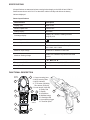
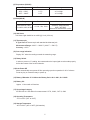
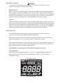
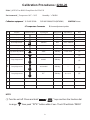
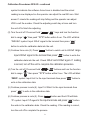
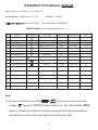
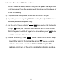
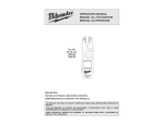
MILWAUKEE ELECTRIC TOOL CORPORATION – TEST & MEASUREMENT PRODUCT
REPAIR SERVICE INSTRUCTIONS — CALIBRATION
2238-20 Clamp Meter for HVAC/R
2239-20 Clamp Meter
Environmental
Condition
Perform all calibration at an ambient temperature of 23°C ± 2°C / 73.4°F ± 3.6°F and relative
humidity of 80% - allow the fork meter to sit at this temperature for a minimum of 30
minutes before proceeding.
REPAIR SERVICE
INSTRUCTIONS
Calibration
MILWAUKEE ELECTRIC TOOL CORPORATION
13135 WEST LISBON ROAD ● BROOKFIELD, WISCONSIN 53005-2550 ● USA
58-92-2238d1 04/2010
TABLE OF CONTENTS
Page
Introduction
1
Precautions and Safety Information
1
Symbols
1
Safety
2
Specifications
3
General Specifications
3
Functional Description
3
Voltage Specifications
4
Current Specifications
4
Resistance Specifications
4
Continuity Specifications
4
Capacitance Specifications
4
Temperature Specifications
5
Hertz Specification
5
Physical and Environment Characteristics
6
Certification and Compliance
6
Basic Maintenance
6
Inserting and Removing the Battery
6
Maintenance - continued
7
Performance Tests
7
Testing the Display
7
Calibration Procedure: 2238-20
8
Calibration Procedure: 2238-20 - continued
Calibration Procedure: 2239-20
9
10
Calibration Procedure: 2239-20 - continued
i
11
Introduction
WARNING
To avoid shock or injury, do not perform the verification tests or calibration procedures
described in the manual unless you are qualified to do so.
The information provided in this document is for the use of qualified personnel only.
CAUTION
The 2238-20 and 2239-20 contain parts that can be damaged by static discharge.
Follow the standard practices for handling static sensitive devices.
Precautions and Safety Information
Use the Meter only as described in the Operator’s Manual. If you do not do so, the protection provided
by the Meter may be impaired. Read the “Safety Information” page before servicing this product.
In this manual, a
WARNING identifies conditions and actions that pose hazard (s) to the user; a
CAUTION identifies conditions and actions that may damage the Meter or the test instruments.
The Symbols
The symbols used on the Meter and in this manual are explained in Table 1.
Table A. The Symbols
Risk of electric shock
See instruction card
DC measurement
Equipment protected by double or
reinforced insulation
Battery
+ +
Earth
AC measurement
Resistance
DC Current
A
Capacitance
Continuity
Temperature
Application around and removal from hazardous
live conductors is permitted.
Conforms to EU directives
C
US
Underwriters Laboratories, Inc.
United States and Canada
Do not discard this product or throw away.
1
SAFETY
Review the following safety precautions to avoid injury and prevent damage to this product or
products connected to it. To avoid potential hazards, use the product only as specified.
WARNING: These statements identify conditions or practices that could result in personal
injury or loss of life.
CAUTION: These statements identify conditions or practices that could result in damage to
the equipment or other property.
Specific precautions
To reduce the risk of injury, user must read and understand operator’s manual.
Do not operate without covers. To avoid personal injury, do not apply any voltage or current to
the product without covers in place.
Electric overload. Never apply a voltage to a connector on the product that is outside the range
specified for that connector.
Avoid electric shock. To avoid injury or loss of life, do not connect or disconnect probes or test
leads from the meter while they are connected to a voltage source.
Do not operate in wet/damp conditions. To avoid electric shock, do not operate this product in
wet or damp conditions.
2
SPECIFICATIONS
All specifications are warranted unless noted typical and apply to the 2238-20 and 2239-20.
Stated accuracies are at 23°C±5°C at than 80% relative humidity and without the battery
indicator displayed.
General specifications
Characteristics
Description
Display count
6000 counts
Numeric update rate
3 times / sec
Polarity display
Automatic
Overrange display
Display "OL" when the reading exceeds
range by 10%
Low voltage indicator
+ +
Automatic power-off time
20 minutes
Power source
12 V Lithium-Ion Milwaukee Battery Pack
49-11-2401, 49-11-2402
Maximum input voltage
1000V CAT lll between IV and COM
Maximum floating voltage
1000V CAT lll between any terminal and earth
ground
V connector
V ,V ,
Temperature Coefficient
0.1×(Spec. Accuracy) / °C, <18°C or >28°C
Battery Run Time
Greater than 12 hours with all functions
is indicated
,
,
FUNCTIONAL DESCRIPTION
R
6
EC TO
4
DE T
1
2
E
AG
LT
O
V
Cat. No.
2239-20
1. Current sensing jaws
2. NCVD sensing area
3. NCVD indicator
4. °F/°C button (2238-20)
Zero button (2239-20)
5.
Inrush button (2239-20)
3
6. Rotary Dial
10
5
6 7. Display
8. Hold button
9. Min/Max button
10. Worklight LED
11. Jaw opening trigger
Cat. No.
12. Terminal inputs
2238-20
7
8
9
3
11
12
Measurement Specifications
Accuracy is ±(% reading + number of digits) at 23°C ± 5°C, less than 80% R.H.
Temperature coefficient: 0.1 * (Specified accuracy)/°C, <18°C, >28°C
(1) DC Voltage
Range
Resolution
600V
0.1V
1000V
1V
Accuracy
±(2% reading + 2 digits)
(2) AC Voltage
Range
Resolution
Accuracy (Sine Wave)
600V
0.1V
±(1.2% reading + 5 digits) (50/60 Hz)
1000V
1V
±(1.8% reading + 5 digits) (45~500 Hz)
(3) DC μ A (2238-20 only)
Range
Resolution
Accuracy
600.0μA
0.1μA
±(1.5% reading + 5 digits)
(4) AC Current
Range
2238-20:
60/600A
2239-20:
60/600/1000A
Resolution
Accuracy
0.01/0.1A
±1.9% rdg ± 5dgt (50/60Hz)
±3.0% rdg ± 5dgt (45-500Hz)
* Add 2% at CF>2
0.01/0.1/1A
(5) Resistance
Range
Resolution
Accuracy
600 Ω/6k Ω/60 kΩ/600 kΩ 0.1 Ω/1 Ω/10 Ω/0.1 kΩ
±1.0% rdg ± 2dgt
(6) Continuity
Range
Continuity Buzzer
600.0Ω
Resolution
Accuracy
Buzzer sounds at 30Ω or less
0.1Ω
(7) Capacitance
Range
Resolution
Accuracy
400μF / 4000μF
0.1μF/1μF
±2.5% ±20dgt
up to 60μF
4
(8) Temperature (2238-20)
Range
Resolution
Accuracy
±1% ±10dgt
±1% ±18dgt
0.1°C
0.1ºF
-40ºC ~ 538ºC
-40ºF ~ 1000ºF
(9) Hertz (2239-20)
Range
Resolution
ACA: 600 Hz, 6 kHz
ACV: 600 Hz, 6 kHz, 60 kHz
0.1 Hz, 1 Hz, 10 Hz
Accuracy
±1%rdg ±1dgt
Sensitivity: Amps 5A RMS;
Volts - 30V RMS
Minimum Hz measurement is 10Hz
(10) Volt Sense
Volt Sense Light should be on at 90V @ 1 inch (2.54 cm).
(11) Thermocouple
K Type Class II Thermocouple with standard dual banana jack.
Measurement Range: -40.0°C ~ 260.0°C (-40.0°F ~ 500.0°F)
Accuracy: ±2.5°C
(12) Over-range Indication
Display “OL” when the reading exceeds the measuring range.
(13) Rotary Switch
In order to prevent a “0” reading, the contacts about the input signal must be made properly
before the contact of the function selection.
(14) Auto Power Off
Meter automatically turns power off after powering up and no operation for 20 ±5 minutes.
Press any key or rotate the rotary to power up.
(15) Battery: Milwaukee 12 V Lithium-Ion Battery Pack: 49-11-2401, 49-11-2402
(16) Battery life:
Approx. 12 hours with all functions
(17) Overvoltage Category
IEC/EN 61010-1 2nd edition for measurement CAT lll, 1000V; CAT lV, 600V
(18) Operating Temperature
-10°C to 50ºC (14ºF to 122ºF)
(19) Storage Temperature
-40°C to 60ºC (-40º to 140ºF) (No batteries)
5
Physical and Environmental Characteristics
Environmental characteristics
Description
Temperature operating
-10 to +50°C
Non-Operating
-40 to +60°C
Humidity (operating)
<80% R.H.
Altitude Operating
2,000M (6560 ft.)
Vibration & shock Operating
MIL-PRF-28800F for Class 2 Instrument
Indoor Use
Certifications and compliances
Safety
Designed to IEC61010-1, UL61010-1 and CSA specifications
Input rating
Category
Ill 1000V.
CAT IV : The source of the Low-Voltage installation.
CAT III : Distribution level mains, fixed installation.
Over voltage category
CAT II : Local level mains, appliances, portable equipment
CAT I : Signal level, special equipment or parts of equipment,
telecommunication, electronics.
Pollution Degree 2
Do not operate in environments where conductive
Pollutants may be present.
Basic Maintenance
WARNING
To avoid shock, disconnect test leads from any voltage source than remove from meter before
opening the case or replacing the battery.
Inserting/Removing the Battery
To remove the battery, use a flat screwdriver
to pry open the lock latch. Push in the release
buttons and pull the battery pack away from
the tool.
Fig. 1
To insert the battery, slide the pack into the
body of the tool. Make sure it latches securely
into place. Press in the lock latch to lock the
battery in place.
Lock latch
6
Maintenance - continued
WARNING
To reduce the risk of personal injury and damage, never immerse your tool, battery pack or
charger in liquid or allow a liquid to flow inside them.
Maintaining Tool
Keep your tool, battery pack and charger in good repair by adopting a regular maintenance program.
After six months to one year, depending on use, return the tool, battery pack and charger to a
MILWAUKEE service facility for service. If the tool does not start or operate at full power with a fully
charged battery pack, clean the contacts on the battery pack. If the tool still does not work properly,
return the tool, charger and battery pack, to a MILWAUKEE service facility for repairs.
Cleaning
Clean dust and debris from charger and tool vents. Keep tool handles clean, dry and free of oil or grease.
Use only mild soap and a damp cloth to clean the tool, battery pack and charger since certain cleaning
agents and solvents are harmful to plastics and other insulated parts. Some of these include gasoline,
turpentine, lacquer thinner, paint thinner, chlorinated cleaning solvents, ammonia and household detergents containing ammonia. Never use flammable or combustible solvents around tools.
Performance Tests
The following performance tests verify the complete operability of the Meter and check the
accuracy of each Meter function against the Meter’s specifications.
Accuracy specifications are valid for a period of one year after calibration, when measured at an
operating temperature of 18°C to 28°C and a maximum of 80% relative humidity.
To perform the following tests, it is not necessary to open the case, no adjustments are necessary,
merely make the required connections, apply the designated inputs, determine if the reading on the
Meter display falls within the acceptable range indicated.
If the Meter fails any of these tests, it needs calibration adjustment or repair.
Testing the Display
Press “HOLD” key while turning the Meter on from the “OFF” position to hold the display in the
Display Test Mode. Compare the display with the example in Figure 2. Turn off the meter to
escape the test mode.
LCD Graphics 2238-20
Figure 2 Display Test
7
Calibration Procedures: 2238-20
Mode:M2238 True RMS Clamp Meter for HVAC/R
Environmental:Temperature 18°C ~ 28°C
Humidity:<70%RH
C a libra tion e quipme nt:1 . FLUKE 5520A
2 . FLUKE 5500A/COIL(50TURNS)
4 . T e mpe ra ture C onne c tor
Switch Position
3 . M 2 2 3 8 Fixture
5 . Screw adjustment probe
Step
Function
Input Signal
Adjustment
Adjust Range
1.
2.
3.
DCV Adjustment
300VDC
ACV Zero Adjustment
Open Circuit
299.9~300.1V
300V/60Hz (sine wave)
VR1
VR2
VR3
ACV Adjustment
4.
DCuA Adjustment
300uADC
VR4
299.9~300.1uA
5.
ACA 600A Adjustment
300A/60Hz
VR5
299.9~300.1A
6.
ACA 60A Adjustment
30A/60Hz
VR6
29.99~30.01A
7.
Capacitor Adjustment
220uF
Soft Key
218.0~222.0
(2)
8.
Capacitor Adjustment
2200uF
Soft Key
2180~2220
(3)
9.
Temp. Adjustment
0mVDC
Soft Key
---
(4)
10.
Temp. Adjustment
16.395mVDC
Soft Key
---
(5)
11.
Temp. Adjustment
0°C
Soft Key
-0.1~0.1°C
(6)
0.0~0.1V
Note
(1)
299.9~300.1V
12.
13.
NOTE:
(1) Turn the unit off. Press and hold “
to range “
+
” keys and turn the function dial
” then push “°F/°C ” button within 2 sec. The LCD will blink “ZERO”
8
Calibration Procedures 2238-20 - continued
symbol to indicate the software forced zero is disabled and the actual
reading is now displayed so the operator can adjust the real AD zero. Wait
around 1 minute the reading will stop falling and the operator can adjust
VR2 to null the number. Check the adjusting result stay at zero and turn
the unit off to finish the adjusting.
(2) Turn the unit off. Press and hold “
dial to range “
+
” keys and turn the function
” then push “°F/°C” button within 2 sec. The LCD will blink
“INRUSH” symbol. Input 220uF signal to the terminal then press “
”
button to write the calibration data into the unit.
” button to switch unit to 4000uF range.
(3) Continue from note (2). Press “
Input 2200uF signal to the terminal then press “
” button to write the
calibration data into the unit. Check 220uF and 2200uF again. If reading
is correct, turn off the unit to complete the calibration procedure.
(4) Turn the unit off. Press and hold “
dial to range “
+
” buttons and turn the function
” then press “°F/°C” button within 2 sec. The LCD will blink
“ZERO” symbol. Input 0mV to the input terminals then press “
” button to
write in the calibration data.
(5) Continue process in note (4). Input 16.395mV to the input terminals then
press “
” to write in the calibration data.
(6) Continue process in note (5). Press “
” button and the LCD will blink
“Ω ” symbol. Input 0°C signal to the input terminals and press “
” button
the write in the calibration data. Check the reading. If the reading is correct,
turn the unit off to complete the process.
9
Calibration Procedures: 2239-20
Mode:M2239 True RMS AC/ DC clamp meter
Environmental:Temperature 18°C ~ 28°C
Humidity:<70%RH
C alibration equipment:
:1 . FLUKE 5520A
2 . FLUKE 5500A/COIL(50TURNS)
3 . M 2 2 3 8 F ix ture
Switch Position
4 . Screw adjustment probe
Step
Function
1.
2.
3.
4.
5.
DCV Adjustment
300VDC
ACV Zero Adjustment
Open Circuit
ACV Adjustment
300V/60Hz (sine wave)
ACA BalanceAdjustment
DCA ZeroAdjustment
ACA 60A Adjustment
6.
7. ACA 600AAdjustment
8. ACA INRUSH Adjustment
Input Signal
Adjustment
Adjust Range
299.9~300.1V
20A/60Hz (sine wave)
VR2
VR4
VR3
VR5
Open Circuit
VR6
-0.03~0.03A
30A /60Hz
29.99~30.01A
300A /60Hz
VR8
VR7
299.9~300.1A
300A/60Hz
VR1
299.0 ~301.0A
(3)
+ INRUSH
0.0~0.1V
Note
(1)
299.9~300.1V
X ± 0.03A
(2)
9.
Capacitor Adjustment
220uF
Soft Key
218.0~222.0
(4)
10.
Capacitor Adjustment
2200uF
Soft Key
2180~2220
(5)
11.
12.
13.
14.
15.
Note:
(1) Turn the unit off. Press and hold “
to range “
+
” keys and turn the function dial
” then push “INRUSH” button within 2 sec. The LCD will blink “ZERO”
symbol to indicate the software forced zero is disabled and the actual reading is
now displayed so the operator can adjust the real AD zero. Wait
10
Calibration Procedures 2239-20 - continued
around 1 minute the reading will stop falling and the operator can adjust VR4
to null the number. Check the adjusting result stay at zero and turn the unit off
to finish the adjusting.
(2) X represents the reading when the wire is at the center of the jaw.
(3) Repeat the procedure of getting “INRUSH” reading then adjust VR1 to make
the reading within the acceptable range.
(4) Turn the unit off. Press and hold “
to range “
+
” keys and turn the function dial
” then push “INRUSH” button within 2 sec. The LCD will blink
“INRUSH” symbol. Input 220uF signal to the terminal then press “
” button
to write the calibration data into the unit.
(5) Continue from note (4). Press “
” button to switch unit to 4000uF range.
Input 2200uF signal to the terminal then press “
” button to write the
calibration data into the unit. Check 220uF and 2200uF again. If the
reading is correct, turn off the unit to complete the calibration procedure.
11