1
EPSON
®
P-80 PORTABLE PRINTER
User's Manual
FCC COMPLIANCE STATEMENT
FOR AMERICAN USERS
This equipment generates and uses radio frequency energy and if not installed and used
properly, that is, in strict accordance with the manufacturer’s instructions, may cause
interference to radio and television reception. It has been type tested and found to comply
with the limits for a Class B computing device in accordance with the specifications in
Subpart J of part 15 of FCC Rules, which are designed to provide reasonable protection
against such interference in a residential installation. However, there is no guarantee that
interference will not occur in a particular installation. If this equipment does cause interference to radio or television reception, which can be determined by turning the equipment off and on, the user is encouraged to try to correct the interference by one or more of
the following measures:
- Reorient the receiving antenna
- Relocate the computer with respect to the receiver
- Plug the computer into a different outlet so that the computer and receiver are on
different branch circuits.
If necessary, the user should consult the dealer or an experienced radio/television technician for additional suggestions. The user may find the following booklet prepared by the
Federal Communications Commission helpful:
“How to Identify and Resolve Radio-TV Interference Problems.”
This booklet is available from the U.S. Government Printing Office, Washington, DC
20402. Stock No. 004-000-00345-4.
WARNING
The connection of a non-shielded printer interface cable to this printer will invalidate the
FCC Certification of this device and may cause interference levels which exceed the limits
established by the FCC for this equipment.
All rights reserved. No part of this publication may be reproduced, stored in a retrieval system,
or transmitted, in any form or by any means, mechanical, photocopying, recording or otherwise, without the prior written permission of Epson America, Inc. No patent liability is
assumed with respect to the use of the information contained herein. While every precaution
has been taken in the preparation of this book, Epson America, Inc. assumes no responsibility
for errors or omissions. Neither is any liability assumed for damages resulting from the use of
the information contained herein.
PX-8 and Geneva are Trademarks of Epson America, Inc.
Portable Scheduler is a Trademark of Epson America, Inc.
Portable WordStar is a Trademark of MicroPro International Corp.
Copyright © 1984 by Epson America, Inc.
Torrance, California 90505
ii
P8492128-0
Y552991020
Contents
Introduction . . . . . . . . . . . . . . . . . . . . . . . . . . . . . . . . . .
1
1
1
1
Setting Up Your P-80 . . . . . . . . . . . . . . . . . . . . . . . . . . .
3
3
5
6
7
9
9
10
11
12
2
Operation and Maintenance . . . . . . . . . . . . . . . . . . . . .
15
15
15
16
17
17
19
22
3
Installing Paper . . . . . . . . . . . . . . . . . . . . . . . . . . . . . . .
23
23
24
24
24
26
26
Control Codes . . . . . . . . . . . . . . . . . . . . . . . . . . . . . . . .
27
27
28
29
29
30
P-80 Features . . . . . . . . . . . . . . . . . . . . . . . . . . . . . . . . .
About This Manual . . . . . . . . . . . . . . . . . . . . . . . . . . . .
4
Printer Preparation . . . . . . . . . . . . . . . . . . . . . . . . . . . .
Covers . . . . . . . . . . . . . . . . . . . . . . . . . . . . . . . . . . . .
Paper guide . . . . . . . . . . . . . . . . . . . . . . . . . . . . . . . .
Ribbon installation . . . . . . . . . . . . . . . . . . . . . . . . . .
Manual-feed knob . . . . . . . . . . . . . . . . . . . . . . . . . . .
DIP Switches . . . . . . . . . . . . . . . . . . . . . . . . . . . . . . . . .
Switch 1 . . . . . . . . . . . . . . . . . . . . . . . . . . . . . . . . . . .
Switch 2 . . . . . . . . . . . . . . . . . . . . . . . . . . . . . . . . . . .
Connecting the P-80 to Your Computer . . . . . . . . . . . .
Switches and Indicators . . . . . . . . . . . . . . . . . . . . . . . . .
The control panel . . . . . . . . . . . . . . . . . . . . . . . . . . . .
Paper control switches . . . . . . . . . . . . . . . . . . . . . . .
Paper-end detector . . . . . . . . . . . . . . . . . . . . . . . . . . .
The Battery and AC Adapter . . . . . . . . . . . . . . . . . . . .
Battery Replacement . . . . . . . . . . . . . . . . . . . . . . . . . . .
Maintenance . . . . . . . . . . . . . . . . . . . . . . . . . . . . . . . . . .
Paper Types . . . . . . . . . . . . . . . . . . . . . . . . . . . . . . . . . .
Paper sizes . . . . . . . . . . . . . . . . . . . . . . . . . . . . . . . . .
Paper Release Lever . . . . . . . . . . . . . . . . . . . . . . . . . . . .
Paper Loading . . . . . . . . . . . . . . . . . . . . . . . . . . . . . . . .
Removing the paper . . . . . . . . . . . . . . . . . . . . . . . . .
The P-80 Self-Test . . . . . . . . . . . . . . . . . . . . . . . . . . . . .
ASCII Codes . . . . . . . . . . . . . . . . . . . . . . . . . . . . . . . . .
Using Control Codes . . . . . . . . . . . . . . . . . . . . . . . . . . .
ASCII Codes as CHR$(n) . . . . . . . . . . . . . . . . . . . . . . .
The ESCape code . . . . . . . . . . . . . . . . . . . . . . . . . . . .
BASIC Example . . . . . . . . . . . . . . . . . . . . . . . . . . . . . . .
iii
5
Combining Print Modes . . . . . . . . . . . . . . . . . . . . . . . .
33
33
34
35
35
36
36
36
37
37
6
Graphics . . . . . . . . . . . . . . . . . . . . . . . . . . . . . . . . . . . . .
39
39
41
41
42
42
43
45
47
47
48
48
A
ASCII Codes and Character Sets . . . . . . . . . . . . . . . . .
ASCII Codes . . . . . . . . . . . . . . . . . . . . . . . . . . . . . . . . .
International Characters . . . . . . . . . . . . . . . . . . . . . . . .
Graphics Characters . . . . . . . . . . . . . . . . . . . . . . . . . . .
Special Characters . . . . . . . . . . . . . . . . . . . . . . . . . . . . .
A-1
A-1
A-3
A-3
A-4
B
Control Code Summary . . . . . . . . . . . . . . . . . . . . . . . .
B-1
C
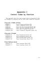
Control Codes By Function . . . . . . . . . . . . . . . . . . . . .
C-1
C-1
C-1
C-1
C-2
C-2
C-2
C-2
D
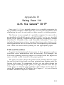
Using Your P-80 with the Geneva PX-8 . . . . . . . . . . . .
D-1
D-1
D-2
Dot-Matrix Printing . . . . . . . . . . . . . . . . . . . . . . . . . . . .
Print Pitches . . . . . . . . . . . . . . . . . . . . . . . . . . . . . . . . . .
Pitch Mode Combinations . . . . . . . . . . . . . . . . . . . . . .
Expandedmode . . . . . . . . . . . . . . . . . . . . . . . . . . . . .
Print Quality Modes . . . . . . . . . . . . . . . . . . . . . . . . . . .
Dress-up Modes . . . . . . . . . . . . . . . . . . . . . . . . . . . . . . .
Mode Conflicts and Priorities . . . . . . . . . . . . . . . . . . . .
Mixing Modes . . . . . . . . . . . . . . . . . . . . . . . . . . . . . . . .
Summary Notes . . . . . . . . . . . . . . . . . . . . . . . . . . . . . . .
iv
Graphics Characters . . . . . . . . . . . . . . . . . . . . . . . . . . .
Dot Graphics . . . . . . . . . . . . . . . . . . . . . . . . . . . . . . . . .
Print Head . . . . . . . . . . . . . . . . . . . . . . . . . . . . . . . . .
Graphics Mode . . . . . . . . . . . . . . . . . . . . . . . . . . . . . . .
Column reservation numbers . . . . . . . . . . . . . . . . . .
PinLabels . . . . . . . . . . . . . . . . . . . . . . . . . . . . . . . . . . . .
A Graphics Program . . . . . . . . . . . . . . . . . . . . . . . . . . .
Graphics Programming Tips . . . . . . . . . . . . . . . . . . . . .
Linespacing . . . . . . . . . . . . . . . . . . . . . . . . . . . . . . . .
WIDTH statements . . . . . . . . . . . . . . . . . . . . . . . . . .
Semicolons and commands placement . . . . . . . . . . .
Character Width (Pitch) . . . . . . . . . . . . . . . . . . . . . . . .
Character Weight . . . . . . . . . . . . . . . . . . . . . . . . . . . . . .
Print Enhancement . . . . . . . . . . . . . . . . . . . . . . . . . . . .
Mode and Character Set Selection . . . . . . . . . . . . . . . .
Line Spacing.. . . . . . . . . . . . . . . . . . . . . . . . . . . . . . . . .
Forms Control . . . . . . . . . . . . . . . . . . . . . . . . . . . . . . . .
Dot Graphics . . . . . . . . . . . . . . . . . . . . . . . . . . . . . . . . .
P-80 and WordStar . . . . . . . . . . . . . . . . . . . . . . . . . . . .
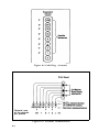
Connecting the Geneva to the P-80 ...............
E
Specifications of the P-80 . . . . . . . . . . . . . . . . . . . . . . .
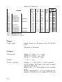
Printing . . . . . . . . . . . . . . . . . . . . . . . . . . . . . . . . . . . . . .
Paper . . . . . . . . . . . . . . . . . . . . . . . . . . . . . . . . . . . . . . . .
Printer . . . . . . . . . . . . . . . . . . . . . . . . . . . . . . . . . . . . . . .
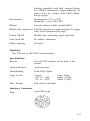
Interface . . . . . . . . . . . . . . . . . . . . . . . . . . . . . . . . . . . . .
Specifications . . . . . . . . . . . . . . . . . . . . . . . . . . . . . . .
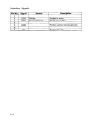
Interface Connector . . . . . . . . . . . . . . . . . . . . . . . . . .
Interface Signals . . . . . . . . . . . . . . . . . . . . . . . . . . . . .
E-1
E-1
E-2
E-2
E-3
E-3
E-3
E-4
V
List of Figures
1-1
1-2
1-3
1-4
1-5
1-6
1-7
1-8
1-9
Unpacking the P-80 . . . . . . . . . . . . . . . . . . . . . . . . .
Identifying the printer parts . . . . . . . . . . . . . . . . . .
Locking lever . . . . . . . . . . . . . . . . . . . . . . . . . . . . . .
Paper guide . . . . . . . . . . . . . . . . . . . . . . . . . . . . . . .
Lifting the front cover . . . . . . . . . . . . . . . . . . . . . . .
Installing the ribbon . . . . . . . . . . . . . . . . . . . . . . . .
Manual-feed knob . . . . . . . . . . . . . . . . . . . . . . . . . .
DIP switches . . . . . . . . . . . . . . . . . . . . . . . . . . . . . .
Connecting the printer cable . . . . . . . . . . . . . . . . .
4
4
5
6
7
8
9
10
13
2-1
2-2
2-3
2-4
2-5
2-6
2-7
2-8
Control panel switches . . . . . . . . . . . . . . . . . . . . . .
Paper control switches . . . . . . . . . . . . . . . . . . . . . .
Plugging in the AC adapter . . . . . . . . . . . . . . . . . .
Removing the screws . . . . . . . . . . . . . . . . . . . . . . .
Lifting the cover . . . . . . . . . . . . . . . . . . . . . . . . . . .
Removing the battery . . . . . . . . . . . . . . . . . . . . . . .
Replacing the power switch cover . . . . . . . . . . . . .
Replacing the battery holder cover . . . . . . . . . . . .
15
17
18
19
20
20
21
22
3-1
3-2
Loading the paper . . . . . . . . . . . . . . . . . . . . . . . . . .
The P-80 self-test . . . . . . . . . . . . . . . . . . . . . . . . . . .
25
26
5-1
5-2
5-3
5-4
5-5
Main columns and intermediate positions . . . . . .
Overlapping dots . . . . . . . . . . . . . . . . . . . . . . . . . .
Comparison between print pitches . . . . . . . . . . . .
Pica and Expanded letters . . . . . . . . . . . . . . . . . . . .
Print quality differences . . . . . . . . . . . . . . . . . . . . .
34
6-1
6-2
6-3
6-4
Pin labels . . . . . . . . . . . . . . . . . . . . . . . . . . . . . . . . .
Pin combinations . . . . . . . . . . . . . . . . . . . . . . . . . .
Data for Space Invader . . . . . . . . . . . . . . . . . . . . . .
Result of incorrect program . . . . . . . . . . . . . . . . . .
44
44
46
49
D-l
Connecting the Geneva to the P-80 ............
D-3
vi
34
35
35
36
List of Tables
1-1
1-2
1-3
1-4
Settings for switch 1 ........................
International character switch settings . . . . . . . . .
Settings for switch 2 . . . . . . . . . . . . . . . . . . . . . . . .
Baud rate switch settings . . . . . . . . . . . . . . . . . . . .
10
11
12
12
4-1
The P-80 and ASCII Codes . . . . . . . . . . . . . . . . . . . . . . .
28
5-1
5-2
Summary of modes . . . . . . . . . . . . . . . . . . . . . . . . .
Typestyles . . . . . . . . . . . . . . . . . . . . . . . . . . . . . . . .
37
38
E-1
Characters...................................................................
E-2
vii
Introduction
The Epson P-80 is a portable, battery-operated printer that enables
you to print anywhere you go. It adds state-of-the-art thermal transfer
technology to other features that have made Epson printers so popular.
P-80 Features
Because the P-80 is lightweight and portable, it is ideal to take along
with you anywhere, yet it still functions as a full-sized printer. Here
are some of the features:
l
l
Uses plain or thermal paper
Contains various print modes that can be combined to produce
different print styles. These include:
Roman and Italic print fonts
Four different print pitches
Bold printing
l
l
l
Has an easy-to-use Underline mode
Creates graphics with two densities and has a special graphics character set to let you create your own charts, diagrams, figures and
illustrations
Generates eight international character sets
About This Manual
Although the P-80 is simple to operate, you will need to take some
time to read this manual and learn about the functions of the printer.
This user’s manual is not long, but it contains a lot of important information.
1
The first three chapters of this manual help you set up, operate, and
maintain your printer. Chapter 4 contains information on how to use
control codes with your printer. Chapter 5 shows you how to combine
print modes and Chapter 6 explains the printer’s graphics features.
The appendixes contain helpful information about selecting print
styles and character sets and about using control codes to obtain certain printer functions. Appendix A lists the control codes and the possible terms for each code. Appendix A also shows the character sets
available on the P-80. Appendix B summarizes the control codes and
Appendix C lists the codes by function. Appendix D gives information on how to use your P-80 with the Geneva TM PX-8™. Finally,
Appendix E provides the specifications for the P-80.
2
Chapter 1
Setting Up Your P-80
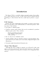
In this chapter, you’ll learn how to prepare your printer for operation and how to connect it to your computer. But first, take inventory.
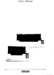
With your P-80 you should receive the items shown in Figure 1-1.
They are:
1. Your P-80 printer
2. Two thermal ribbon cassettes
3. An AC adapter
4. Five sheets of paper
5. This P-80 Printer User’s Manual
Remove any packing adhesive or packing pads that you see. It’s a
good idea to save all your packing materials. You may want to store
or ship your printer someday.
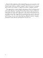
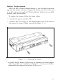
Printer Preparation
Once you have verified that all the items for the printer are
included, you’re ready to prepare the printer for operation. Start by
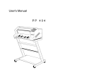
identifying the printer’s main parts (see Figure l-2). Take a couple of
minutes to familiarize yourself with these parts and their names.
Figure l-2 shows how the printer will look when you finish preparing
it for operation.
Note: Do not turn on the P-80 until you complete the printer preparation.
3
Figure 1-1. Unpacking the P-80
(Top view)
Figure 1-2. Identifying the printer parts
4
Covers
The front and back covers are designed to keep your P-80 free from
dust. It is a good idea to keep them closed when your printer is not in
use.
The front cover protects the print mechanism and reduces the noise
level when the printer is on. The serrated edge serves as a convenient
tear-off point.
It’s a good idea to keep the front cover closed while printing as it
helps guide the paper out of the printer. You only need to lift this cover
when you are installing a ribbon cassette.
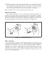
There is a plastic gray lever on the left side of your printer. This
lever holds the back cover shut. Notice the words OPEN and LOCK.
Ignore the words FEED and FREE, above and below the lock lever, for
now. They deal with paper installation functions (discussed in Chapter 3).
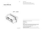
To unlock the back cover, push the lever to the open position (see
Figure l-3). To lock it, hold the back cover shut and pull the lever to
the lock position.
Figure 1-3. Locking lever
When you release the lock lever, the back cover pops up slightly.
Push the cover back until it stands vertically as shown in Figure 1-3.
The back cover now has a new function. It serves as your paper guide.
5
Note: Before you continue, take a moment to look inside your
printer. You will see a gray bar with a line and the word paper.
Remove the thin transparent strip covering this bar.
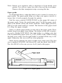
Paper guide
As mentioned above, when the back cover is vertical, it serves as a
paper guide. The paper guide helps you align your paper correctly to
ensure that it feeds properly through the printer.
Find the arrow marked PAPER STAND on the upper left comer of
the paper guide. Notice the metal paper stand. To lift the paper stand,
place your thumb where the arrow indicates. With slight pressure,
pull up on the stand until it is vertical. The function of the paper stand
is to keep the paper straight.
There is a plastic paper holder at each side of the paper guide. These
holders keep your paper from sliding. The holder on the left is stationary and is labelled LEFT EDGE. The right holder is a sliding scale that
will accommodate paper from 5½ to 8½ inches wide. When closing
the back cover, make sure the right holder is pushed all the way to the
right. Otherwise, the cover will not close properly.
Three arrows indicate the paper widths most often used. The first
one is marked INVOICE, the second B5, and the third A4•LEGAL.
The A4•LEGAL is the one you use for 8½-inch wide paper.
Figure 1-4. Paper guide
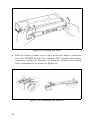
Ribbon installation
When you are using thermal paper, you do not have to install the
ribbon cassette. With any other type of paper, install the ribbon cassette as described below. Chapter 3 gives an explanation of the types
of paper to use.
Before installing the ribbon cassette, you need to lift the front cover
(Figure l-5). Firmly grasp both sides of the cover and pull up. It should
tilt toward you easily. If you happen to lift the cover off completely,
replace it by positioning the hinge at each end of the cover over the
hinge posts at the front of the printer. The hinges allow you to easily
open and close the cover without removing it.
Figure l-5. Lifting the front cover
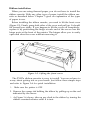
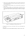
The P-80’s ribbon cassette is easy to install. You never have to
worry about getting ink on your hands. Just follow these simple steps
and refer to Figure 1-6 for quick installation:
1. Make sure the printer is OFF.
2. Remove the orange tab holding the ribbon by pulling up on the end
indicated by the arrow.
3. As Figure 1-6 shows, take up any slack in the ribbon by turning the
ribbon counterclockwise until it is taut.
Figure 1-6. Installing the ribbon
8
4. Hold the cassette so that the exposed ribbon is on the left side and
the closed ends of the ribbon holes are on top. Place the cassette
over the print mechanism. Make sure the ribbon is placed in front
of the silver print head. Press down and snap it into place.
That’s all there is to it. Now just close the front cover.
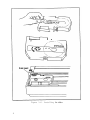
Manual-feed knob
The manual-feed knob is used to advance the paper manually. It is
located on the right side of your printer. When your printer is packed,
the knob is pushed in flush with the right side. To bring it out, push the
center of the knob in and release it. The knob should pop out. To feed
the paper manually, turn the knob clockwise. See Figure 1-7.
Figure 1-7. Manual-feed knob
DIP Switches
Two groups of switches, called DIP switches, are located at the
back of your printer (Figure l-8). The first group of four switches is
referred to as switch 1 and the second group of eight switches is
referred to as switch 2. These switches are set at the factory, and you
probably won’t need to touch them. You may, however, want to take
the time to learn about the switches and their functions in case you
need to make adjustments.
Figure 1-8. DIP switches
Note: Make certain the printer is turned OFF when you change DIP
switch settings. The P-80 checks these settings only at powerup and it will ignore any changes made with the power on
(until it is turned off and back on).
Switch 1
The functions of the four switches that make up switch 1 are summarized in Table 1-1.
Table l-l. Settings for switch 1
Switch No.
1-1
1-2
1-3
1-4
Function
OFF
ON
International Character Sets
(See Table 1-2.)
Auto line feed
(AUTO FEED XT
signal)
No auto
line feed
Auto line
feed
with CR
Factory setting
ON
ON
ON
OFF
Switch 1-1, 1-2, 1-3 - These switches are used to determine the default
international character set. The factory-set condition is for the U.S.A.
characters. Table 1-2 shows the required switch settings for each set.
Appendix A shows the characters included in each of the character
sets.
10
You can also access the International characters by using a control
code. See Chapter 4 for an explanation of control codes and Appendix
B for the appropriate code.
Table 1-2. International character switch settings
Country
U.S.A.
France
Germany
England
Denmark
Sweden
Italy
Spain
SW 1-1
SW 1-2
SW 1-3
ON
OFF
ON
OFF
ON
OFF
ON
OFF
ON
ON
OFF
OFF
ON
ON
OFF
OFF
ON
ON
ON
ON
OFF
OFF
OFF
OFF
Switch 1-4 - This switch controls the automatic line feed. The factory-
set condition is OFF which means the computer must send line feeds.
When this switch is ON, the printer performs an automatic line feed
with each carriage return.
If you are not sure if your computer sends a line-feed code to the
printer at the end of each print line, leave the switch the way you find
it. You can change this switch if your first printing occurs all on one
line or with the lines spaced twice as far apart as you requested.
Switch 2
The P-80 uses the RS-232C serial interface to communicate data
from your computer to the printer. The switches which make up
switch 2 are used to set up the proper serial communications for the
RS-232C serial port.
The factory-set condition is shown in Table l-3 and should be
appropriate for most computers. If you have any problems getting
data to print correctly from your computer, consult your computer
manual or ask your dealer.
11
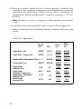
Table 1-3. Settings for Switch 2
Switch No.
SW-2-1
2-2
2-3
2-4
2-5
2-6
2-7
2-8
Function
Data bit length
Party check
Parity
Stop bit
OFF
ON
8 bits
7 bits
No
Yes
Odd
2 bits
Even
1 bit
Factory setting
OFF
OFF
OFF
OFF
ON
Baud rate setting
(See Table l-4.)
OFF
ON
OFF
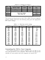
The factory-set baud rate for the P-80 is 4800. If your computer
requires another baud rate, the following chart gives the appropriate
DIP switch settings.
Table l-4. Baud rate switch settings
DIP2-5
DIP2-6
DIP2-7
DIP2-8
Bit rate (bps)
ON
ON
ON
ON
ON
ON
ON
ON
ON
ON
ON
ON
ON
ON
ON
75
110
134.5
150
200
300
600
1,200
1,800
2,400
4,800
9,600
300
1,200
2,400
9,600
OFF
ON
OFF
ON
OFF
ON
OFF
ON
OFF
ON
OFF
ON
OFF
ON
OFF
OFF
OFF
ON
ON
OFF
OFF
ON
ON
OFF
OFF
ON
ON
OFF
OFF
OFF
OFF
OFF
OFF
ON
ON
ON
ON
OFF
OFF
OFF
OFF
OFF
OFF
OFF
OFF
OFF
OFF
OFF
OFF
Connecting the P-80 to Your Computer
Your printer preparation is almost complete. Now it’s time to connect your printer to your computer. First make sure the power
switches for your printer and your computer are turned OFF.
12
For many computers, you merely plug the printer cable into your
computer. However, some computers require a printer interface card,
either mounted inside or outside the computer. Check your computer
installation or operations manual for details on how to connect your
computer to your printer, or consult your dealer.
As mentioned above, the P-80 uses the RS-232C serial interface (but
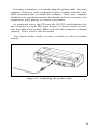
the connector is a 6-pin DIN type). Figure 1-9 shows where you connect the cable to the printer. Make sure that the connector is aligned
correctly. Don’t force it into the socket.
Your Epson dealer stocks a variety of cables as well as interface
boards.
Figure l-9. Connecting the printer cable
13
Chapter 2
Operation and Maintenance
Your P-80 is now connected to your computer and ready for operation. In this chapter you’ll learn how to use the controls and indicators
on the printer to operate it correctly. You’ll also learn how to recharge
the battery and maintain your P-80 to keep it printing smoothly for a
long time.
Switches and Indicators
The few switches and indicators on the P-80 require a brief explanation so that you can have a better understanding of how to use them.
The printer does not have to be connected to your computer to test
these switches.
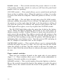
The control panel
The control panel switches are located on the top (right comer) of
your printer (Figure 2-l). These switches control the main functions of
the printer. Here is what they do:
Figure 2-1. Control panel switches
15
POWER switch — This switch activates the power when it is in the
ON position. Push this switch on and you will hear the print head
prepare itself for printing.
ON LINE switch — This switch allows you to switch back and forth
from on-line to off-line status. When the printer is on-line, it is ready
to receive data from the computer. When the printer is off-line, it is not
ready.
ON LINE light — The red light, located above the ON LINE switch,
indicates whether the printer is on or off line. The light glows red when
the printer is on-line, and when the light is off, the printer is off-line. If
you turn the power ON without any paper in the printer, the ONLINE light will not glow, even if you press the ON-LINE switch.
The ON LINE light blinks when the motor has locked or the battery
is low. When the light is blinking, first check to see if the paper or
ribbon cassette is stuck. If either of these is stuck, turn the power off
and correct the problem. The ribbon cassette should return to the
starting position on the left side when you turn the power back on. If
you can not find anything wrong with the printer, the blinking light is
indicating that your battery is low. Turn the power OFF and plug in
the AC adapter as described later in this chapter.
PAPER FEED switch — This switch allows you to automatically
advance the paper one line at a time. You can only activate this switch
when the printer is off-line. Tap this switch to advance the paper one
line at a time. Hold the switch down to advance the paper several lines
at once.
Paper control switches
There are two switches located on the right side of your printer
(Figure 2-2). These switches allow you to make certain adjustments to
improve the print quality on your paper.
DENSITY switch — This switch makes the print lighter or darker.
Move the switch toward the back of the printer to make the print
lighter; move the switch toward the front of the printer to make it
darker.
16
Figure 2-2. Paper control switches
PAPER SURFACE switch — This switch adjusts the print head speed
to improve the print quality on standard paper. Push this lever toward
the front when using coarse paper; push it back when using smooth or
thermal paper.
Note: You have to set the paper surface switch with the power OFF
for the change to take effect.
Paper-out sensor
The P-80 is equipped with a device that warns you when the printer
is at the end of the paper. When your paper reaches the end, the ON
LINE light goes off and printing stops.
To resume printing, place another sheet of paper into the printer,
and press the ON LINE switch. If you do not want to resume printing,
turn the power OFF and back ON again. Each time the printer is
turned ON, it reinitializes-resets to its settings at start up.
The Battery and AC Adapter
Note: Charge the battery with the AC adapter before using your
printer for the first time. To do this, follow the instructions
given below for charging the battery.
The P-80 will print approximately 60,000 characters (or 30 pages on
8½ by 11 paper with 2,000 characters each) on a fully charged battery.
17
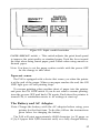
The battery needs charging when the print becomes very slow and
the ON LINE light blinks. To charge the battery, first turn the power
OFF. Then plug the AC adapter into the back of the printer as shown
in Figure 2-3. The battery charges in six to seven hours.
Figure 2-3. Plugging in the AC adapter
The printer can be used with the AC adapter connected without
waiting for the battery to charge. However, when you are finished
printing, switch the power off and charge the battery for six to seven
hours.
Once you unplug the adapter, let the printer run on its own until it
needs recharging. Recharging the battery more often than needed can
weaken it.
WARNING: Do not charge the battery for more than 24 hours. Also,
do not leave the power switch ON when recharging the
battery and the printer is not in use. Doing either of
these may severely shorten the battery life.
18
Battery Replacement
Your P-80 uses a nickel cadmium battery. If the red light keeps flashing after the battery has been charged, the battery has come to the end
of its life and must be replaced. Nickel cadmium batteries are available
through your Epson dealer.
To replace the battery, follow the steps below.
1. See that the power switch is OFF,
2. Remove the two screws on the battery holder cover at the back of
the printer by using a Phillips screwdriver (Figure 2-4).
Figure 2-4. Removing the screws
3. Carefully lift the battery holder cover by placing your index fingers
at the top of the cover as shown in Figure 2-5, and your thumbs
underneath the ridge at the bottom of the cover.
19
Figure 2-5. Lifting the cover
4. With the battery holder cover open, locate the battery connector
near the POWER switch. It is marked CN7. Unplug the battery
connector noting the direction of insertion. Remove the battery
with a screwdriver as shown in Figure 2-6.
Figure 2-6. Removing the battery
20
5. Place the new nickel cadmium battery into the battery holder with
the connector cable at the bottom. Insert the battery connector into
the slot marked CN7.
6. To reinstall the battery holder cover, you first need to remove the
front cover.
7. Push the battery holder cover back into place, at the back of the
printer, seeing that the tabs on each side are inside the cover, and
the switches and indicator light fit properly in their slots (Figure
2-7).
Figure 2-7. Replacing the battery holder cover
8. Replace the two screws at the back of the cover and replace the
front cover.
WARNING: Do not disassemble the battery or throw it into a fire.
21
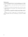
Maintenance
As with any mechanical device, the best maintenace of your P-80 is
preventive maintenance. Here are some general guidelines to follow:
1. Keep your printer in a safe, clean location away from extreme temperatures.
2. Clean particles and dust from the printer with a soft cloth or brush.
3. Clean the outside of the printer with a mild cleanser when it
appears dirty.
4. If your printer is not operating correctly, do not attempt to repair it
yourself. Take your printer to an authorized Epson dealer for service.
Although your P-80 is solidly built, it’s not indestructible. If you
treat your printer with care, it should give you years of reliable
service.
22
Chapter 3
Installing Paper
By this point, you’re probably anxious to start printing. In this
chapter, you’ll learn the different types of paper your P-80 can use and
how to install the paper. Then you can start to print by having the
printer perform a self-test.
Paper Types
The type of paper to use with your P-80 is thermal paper. It will give
you the best quality print. Since thermal paper is heat-sensitive, you
do not need to use the ribbon cassette.
Thermal paper prints only on the glossy side, the side that is slightly
darker. If the glossy side is not facing the print head, nothing prints.
Observe the following precautions in handling and storing thermal
paper:
l
l
l
Do not attach plastic adhesive tape to the paper.
Handle the paper carefully so as not to bend or stain it. Damaged
areas may become discolored or fail to print.
Do not store the paper in hot, humid places (cars, heaters, direct
sunlight).
When you are printing rough drafts, you can use smooth finish
paper like the sample sheets included with your printer. It is necessary
to use a ribbon cassette with this type of paper. Your Epson dealer can
assist you with the correct types of paper to use with your P-80.
23
Remember to adjust the PAPER SURFACE switch for the type of
paper you are using. For coarse paper, set the switch to RGH; for
smooth or thermal paper, set the switch to SMT.
Paper sizes
The printer uses single-sheet paper and handles any paper the width
of the platen (8½ inches) or narrower. You can also use continuousfeed paper or roll paper.
The right paper holder will not hold paper narrower than 5½
inches. When you use paper that is narrower than 5½ inches, make
sure that the paper stays straight as it is feeding through the printer.
Otherwise, your print lines may slant across the paper.
Paper Release Lever
The lock lever on the left side of your printer serves as a paper
release lever. Notice the words FEED and FREE above and below the
lever. In the FEED position, the roller inside the printer holds the paper
and causes it to feed through the printer. The FREE position allows
you to make adjustments if the paper is not aligned correctly in the
printer.
Paper Loading
There are a couple of adjustments to make before loading your
paper. Check to see that the lock lever is in the FEED position and the
paper stand is all the way up. Slide the right holder all the way to the
right side of the printer. Follow these steps to load your paper:
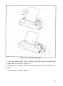
1. Place your paper at the top of the paper guide and slide it underneath the left holder (Figure 3-l).
2. Adjust the right holder to the width of the paper (unless your paper
is less than 5½ inches wide).
3. Make sure the paper is straight and placed in the printer as far as it
can go.
24
Figure 3-1. Loading the paper
4. Turn the manual-feed knob clockwise until the paper feeds through
to the front as shown in Figure 3-1.
5. Put the power switch in the ON position if you have not done so
already.
You are now ready to print.
25
Removing the paper
When you are finished printing, remove the paper by using the
manual-feed knob. If your paper is almost out of the printer, you can
release it by placing the lock lever in the FREE position.
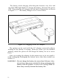
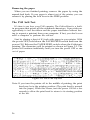
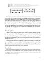
The P-80 Self-Test
It’s time to see how your P-80 operates. The P-80 self-test is a builtin program that prints all the standard characters. It provides an
opportunity to test the ribbon and the paper installation without having to request a printout from your computer. If fact, you don’t even
need a computer to perform the self-test.
Start by placing a sheet of 8½-inch wide paper in your printer. With
the power OFF, hold down the PAPER FEED switch and turn the
power ON. Release the PAPER FEED switch when the P-80 starts
printing. The characters will be printed as shown in Figure 3-2. The
printer will continue indefinitely until you turn the power OFF or run
out of paper.
Figure 3-2. The P-80 self-test
Note: If you turn the printer off in the middle of printing, the print
head may be in the printing position. (The print head is pressed
into the paper.) When this occurs, turn the power ON for a few
seconds to allow the print head to return to its starting position
at the left.
26
Chapter 4
Control Codes
This chapter explains how a computer uses control codes to send
instructions to your printer. Specifically, you’ll learn how the control
codes work with the P-80. (Appendix A shows a complete listing of all
the P-80 control codes.)
If you are going to use your printer with commercial software packages, it is not necessary for you to read this chapter. You can follow
the printer installation instructions given in your computer or software manual. Most software packages include installation routines
for dot matrix printers. It may be that you only have to specify which
type of printer interface, such as RS-232C, you are using.
Note: As mentioned in Chapter 1, the P-80 uses the RS-232C serial
interface. If your software asks for specifications you do not
understand, consult your dealer for assistance.
ASCII Codes
Since there are many different kinds of computers and many
different kinds of printers, almost all computers use a standard set of
codes to communicate with printers. This set of codes is called the
American Standard Code for Information Interchange (ASCII).
Pressing a character key on your computer produces a bit pattern
representing a particular ASCII (pronounced “ask-ee”) code. The code
is interpreted by the printer, which responds by printing the letter,
number, or symbol desired. Control codes control specific printer
functions.
Most of the 256 ASCII numbers are codes for specific characters.
Typically, codes 32 through 126 are reserved for the standard set of
27
alphanumeric characters and special symbols. For instance, 65 represents the capital letter “A”, while 90 represents the capital letter “Z.”
On the P-80, the graphics character set is stored at codes 128 through
159. Other ASCII numbers control computer and printer functions.
Table 4-1 summarizes the range of the ASCII codes used by the
P-80. Appendix B summarizes the functions for each of the ASCII
control codes.
Note: Codes can be expressed in binary, hexadecimal, or decimal
form. For ease of understanding, we use the decimal form.
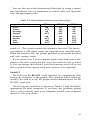
Table 4-1. The P-80 and ASCII Codes
ASCII code group
1 to 32
33 to 126
128 to 159
P-80 Interpretation
Printer control codes
Standard (roman) character set
Graphics character set
In summary, some ASCII codes produce standard characters and
special symbols, some produce graphics characters, and others control the printer’s functions.
Using Control Codes
Most of the time you don’t have to give this code system much
thought. When you are using a word processing system, you press the
letter A on the keyboard, and the computer prints the letter A on the
printer.
Some ASCII codes, however, don’t have characters on the keyboard. The most important of these are the ASCII codes that have
values less than 32. As mentioned above, these codes are the printer
control codes. Most keyboards can produce these codes by holding
down the control key (often marked CTRL) while pressing a letter
key. The combination of CTRL/M produces ASCII 13, which is the
code to start a new line, and referred to as a carriage return. The
28
following chart shows many different ways of referring to the code for
the carriage return function.
Carriage return
CR
13
0DH
CTRL/M
CHR$(13)
Its common name
The abbreviation of its name
The decimal ASCII code
Its hexadecimal ASCII code
Its control-code name
Its usage in BASIC
As you can see there are many different ways to refer to a single
code. This information helps you identify what code is being
referenced. Your computer manual may refer to ASCII 13 while your
software program refers to CTRL/M. You now know that both refer
to the same code.
ASCII Codes as CHR$(n)
The ASCII codes take on a new form when you use them with
programming languages. For example, in BASIC, the ASCII codes
take the form of CHR$(n), where n represents the desired code. The
capital letter A, which is the ASCII code 65, is CHR$(65). You are
telling the computer which code you want by inserting the number
within the parentheses following the CHR$. Depending on the code,
you instruct your printer to print a character, or perform a function
(such as execute a line feed or print italics).
The ESCape code
So many features have been added to printers that even 256 ASCII
codes are inadequate if only single-code CHR$ instructions can be
used. Because of this, the logic of the P-80 has been designed to understand special sequences of control codes, the ESCape code sequences.
This permits major expansion to the availability of control codes.
Each ESCape code sequence consists of the ESCape code (usually
abbreviated (ESC)), which is CHR$(27), plus one or more of the
other P-80 CHR$ codes. You use these code sequences to select one or
more printing features, or modes.
For example, the ESCape code used to turn the italic print function
on is <ESC>“4”. The (ESC) is the abbreviation for CHR$(27) and the
numeral 4 is the ASCII equivalent of CHR$(52). The <ESC>“4” is easier to remember than CHR$(27)CHR$(52).
29
You will have a better understanding of how the (ESC) codes work
when you use them in your programming. Appendix A lists all the
ASCII codes and Appendix B summarizes their functions.
A BASIC example
Keep in mind that the ASCII codes and the ESCape sequences are
mostly used with programming languages. One example is to use
your printer to print listings of your programs.
Different computer systems access the printer in different ways. For
example, most computers that use Microsoft BASIC send PRINT or
LIST commands to the printer by adding a leading L to a screen command: LPRINT, LLIST. Your computer may not use these commands.
If you are not familiar with your computer’s command conventions,
check its manual.
We use BASIC in the following programs since it is widely used in
portable computers. If necessary, substitute the commands required
by your computer.
Once you have discovered how your computer communicates with
the printer using BASIC, enter the following program lines into your
computer.
10 LPRINT CHR$(27);"-1";
20 LPRINT "Underline"
Now list the lines on the printer using your computer’s version of the
LLIST command. RUN the program, and you’ll get this:
Underline
With the underline mode, you can underline characters or blank
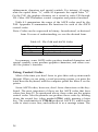
spaces, which is useful when creating forms that have lines for signatures or data. See this for yourself by adding these lines to your program. Enter 10 blank spaces in line 30 and 15 blank spaces in line 40.
30 LPRINT "
40 LPRINT "
"
"
Run your program. The result is:
Underline
30
Underline mode does not use the underline character which is probably used in your word processing software. Since the underline character is only five dots wide, it does not print in the space between each
text character. Type and run a new program:
NEW
10 FOR X=1 TO 41: LPRINT CHR$(95);: NEXT X
20 LPRINT CHR$(13);
30 LPRINT "THIS PROGRAM USES THE UNDERLINE
CHARACTER"
THIS PROGRAM USES THE UNDERLINE CHARACTER
The printer’s underline mode, used in the example on the previous
page, provides you with an idea of how a programming language can
be used. There are many tutorial books available if you would like to
learn more about using BASIC with your printer.
31
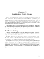
Chapter 5
Combining Print Modes
One of the most pleasing aspects of your P-80 printer is its variety of
print modes that can be combined to make different typestyles. You
access these print modes through programming languages such as
BASIC. You can also access them through your word processing program, if your program allows you to insert print commands in the
text (for example, Portable WordStar’“).
This chapter gives a short explanation of how dot matrix characters
are formed, briefly describes the different print modes, and then
shows you how the print modes can be combined.
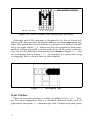
Dot-Matrix Printing
The P-80 uses a dot matrix to plot the characters it prints. Vertically,
the matrix consists of 6 main and 5 intermediate columns. Horizontally, the matrix consists of 9 rows.
The P-80 characters are designed to be five or fewer columns wide.
The sixth column is left blank to allow for space between text characters (some of the graphics characters use the sixth column).
Because the use of 5 dots does not give enough detail for the highest
quality characters, the P-80 prints some dots half way between the
main columns in the 6-dot-wide matrix. This enhancement results in a
matrix grid that is actually 11 dots wide-6 main columns with 5 intermediate columns. You can count the 11 positions on the grid shown in
Figure 5-l.
33
Figure 5-1. Main columns and intermediate positions
Although each P-80 character is designed to be five or fewer columns wide, dots can also be placed midway between each main column. This means that the dot pattern is printed twice, shifted one half
dot to the right. Figure 5-2 shows how the dots printed in these intermediate columns actually overlap with those in the main columns.
You can see this difference between the dots shown in Figure 5-l and
the overlapping dots in Figure 5-2. (An example of a print mode using
overlapping dots is shown later in this chapter.)
Figure 5-2. Overlapping dots
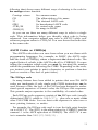
Print Pitches
There are two print pitches (or widths) available on the P-80. They
are Pica and Compressed. Pica is a standard character width used on
typewriters and prints 10 characters per inch. Compressed pitch prints
34
just over 17 characters per inch. The smaller characters allow for
spreadsheets, or other work that requires compact printing, to be
squeezed on an 8½-inch page.
In Figure 5-3, you can see the difference in the two pitches. Pica is
the default, the pitch in effect when the printer is turned on.
1 inch
Pica
ABCDEFGHIJKLMNOPQRSTUVWXYZab
Compressed
ABCDEFGHIJKLMNOPQRSTUVWXYZabcdefghijklmnopqrstuv
Figure 5-3. Comparison between print pitches
Pitch Mode Combinations
Expanded is a print mode that can be used with either Pica or Compressed print pitches. You can add this mode to your program to printout for one line only or for longer passages. Expanded can also be used
with most of the other modes.
Expanded mode
Expanded mode doubles the width of the current pitch mode. It
does this by printing twice as many dots, twice as wide, as you can see
in Figure 5-4.
Pica A
Expanded A
Figure 5-4. Pica and Expanded letters
35
Print Quality Modes
There are two modes that produce boldface (darker) characters
which make your printout more distinctive. These modes are DoubleStrike and Emphasized. Each gets its bold effect by printing overlapping dots as explained earlier in this chapter. Figure 5-5 shows the
difference between Single-Strike (the default), and Emphasized.
On the P-80, Double-Strike and Emphasized produce the same
result. Double-Strike may produce a slightly different result when
printed through your software.
Figure 5-5. Print quality differences
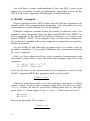
Dress-up Modes
There are two more modes you can mix with any of the other
modes to give your printouts a finished touch-Italic and Underline.
Italic characters are printed in a typeface completely different from
the more usual Roman characters. Any computer system can select
Italic mode without software adjustments.
The P-80 has a built-in Underline mode making it easy for you to
underline anything. You can underline characters or blank spaces as
demonstrated in Chapter 4.
Mode Conflicts and Priorities
Print modes have an order of priority; some modes are assigned
greater value than others. Also, certain modes can be combined and
others cannot. If two modes which are not equal in value are used
36
together, the one with less priority is temporarily ignored. Only when
the higher priority mode is turned off, will the lower priority mode
take effect.
For example, suppose you activate both Emphasized and Compressed. Since these modes cannot be combined, the printer must
make a choice. In this case, the printer chooses Emphasized because it
is assigned higher priority (see Table 5-l).
Table 5-1. Summary of modes
Emphasized
Compressed
Double-strike
Mixing Modes
Not all mode combinations create conflicts. You can combine most
modes to produce the different typestyles shown in Table 5-2 at the
end of this chapter. Appendix B gives you the commands needed to
instruct the printer to print any combination of these modes.
Summary Notes
1. Pica is the default pitch and is active when Compressed is turned
off.
2. The two modes that produce boldface characters are DoubleStrike and Emphasized. Single-Strike is the default.
3. Double-Strike
and Emphasized produce the same result.
37
4. When two modes conflict, the one of lesser priority is masked (not
cancelled). For example, Compressed and Emphasized cannot be
printed at the same time. When both are active, printing is in
Emphasized. When Emphasized is cancelled, printing is in Compressed.
5. When Expanded is active, Compressed takes priority over Empha-
sized.
6. Emphasized and Double-Strike will not mix with Compressed.
7. Italics, Underline, and Expanded modes combine with any print
mode.
Table 5-2. Typestyles
Italic
Underline
Italic
Underline
ABCD
ABCD
AECD
ABCD
ABCDEFG
ABCDEFG
ABCDEFG
ABCDEFG
Single-Strike Emphasized Pica ABCD
ABCD
ABCD
ABCD
ABCD
ABCD
ABCD
ABCD
AB
AB
AB
AB
ABC
ABC
ABC
ABC
A B
AB
AB
AB
AB
AB
AB
AB
Normal
Print
Single-Strike Pica
Single-Strike Compressed
Double-Strike Pica
Single-Strike
Expanded Pica
Single-Strike
Expanded Compressed
Single-Strike Emphasized
Expanded Pica
Double-Strike
Expanded Pica
38
Chapter 6
Graphics
Your P-80 is capable of printing special graphics characters and dot
graphics, but you do need some programming knowledge to use these
graphics features. This chapter is included for those who wish to
design their own programs to take advantage of the printer’s graphics
capabilities.
Some computers allow you to draw figures on the screen using
graphics characters and then dump them to the printer using a screen
dump command. Check your computer’s documentation to see if it
contains this feature.
Graphics Characters
The P-80 contains a set of special graphics characters which are the
same graphics characters available on the GenevaTM PX-8™. The
graphics characters are accessed with ASCII codes 128 through 159. If
your computer cannot access codes greater than 127, you will not be
able to use the graphics characters.
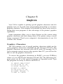
To access the graphics characters in BASIC, you use CHR$(n)
where n is an ASCII code between 128 and 159. The following program prints out all of the special characters in Expanded mode. Type
the program in exactly as shown and RUN it.
10
20
30
40
50
60
70
LPRINT CHR$(27)"W1"
FOR X=128 TO 138
LPRINT CHR$(X)" ";
NEXT X: LPRINT
FOR X=139 TO 149
LPRINT CHR$(X)" ";
NEXT X: LPRINT
39
80 FOR X=150 TO 159
90 LPRINT CHR$(X)" ";
100 NEXT X: LPRINT
110 LPRINT CHR$(27)"@"
Remember that you can print these characters in different pitches
and weights. For example, if you want to see them in Pica, delete line
10 from your program to produce the result below.
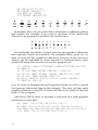
You probably can think of many uses for the graphics characters
that represent objects and symbols. The program below gives you an
idea of how the line graphics characters (shown in the first row
above), can be combined to create artworks or business forms. Type
in the following lines but do not run the program yet:
10
20
30
40
50
60
70
LPRINT CHR$(27)"A"CHR$(7)CHR$(27)"E"CHR$(27)"W1"
READ R
IF R>0 THEN LPRINT CHR$(R);: GOTO 20
IF R=0 THEN LPRINT: LPRINT CHR$(27)"@": END
IF R=-1 THEN LPRINT: GOT0 20
N=-R: READ R: FOR K=1 TO N: LPRINT CHR$(R);
NEXT K: GOT0 20
Line 10 turns on Emphasized and Expanded Modes as well as special
line spacing (discussed later in this chapter). The next six lines print
graphics characters using DATA from the lines to be added in the next
stage of the program.
Add these DATA lines to produce a four-part box with graphics
characters in each part:
80 DATA 135,-6,133,130,-6,133,136,-1
90 DATA 134,-6,32,134,32,154,32,,154,32,154,134,-1
100 DATA 134,144,143,144,143,144,143,134,-6,32,134,-1
110 DATA 132,-6,133,128,-6,133,131,-1
40
120 DATA 134,-6,32,134,-6,149,134,-l
134,152,32,152,32,152,32,134,-6,32,134,-1
130 DATA
140 DATA 137,-6,133,129,-6,133,138,0
Now that you have seen the program work, you can substitute
your own DATA lines to make it print any combination of graphics
characters you need. Notice that each DATA line corresponds to a
print line, and each ends with -1, except for the last, which ends the
program with a zero. For spaces, you use 32, the ASCII code for a
space. You can repeat any character, including the space, by entering
the number of repetitions as a negative number followed by the number of the character to be repeated. For example, the first part of line
90 supplies the DATA for one vertical line (character 134), six spaces,
and another vertical line.
Dot Graphics
Think of your piece of paper as an artist’s canvas waiting for the
images you create. With dot graphics, you use dots instead of brushstrokes to form your pictures and designs. If you plan carefully where
you want the dots to appear and use your computer to give the printer
the proper instructions, your P-80 will generate nearly any pattern or
figure you wish.
Printing high-resolution graphics on the P-80 requires a mode that
is very different from text modes. In dot graphics mode, none of the
predefined characters or symbols in the printer’s memory is used.
Instead, you create the patterns of dots that are printed. Thus, you
control where each and every dot is printed.
Print Head
For each column position on a print line, the print head impresses
the pattern of dots that you have specified. Before you can start
designing these patterns, you need to know a little more about the
way the print head works.
41
Each time the print head makes a horizontal pass, it prints a pattern
of dots. To print figures taller than 7 or 8 dots, the print head must
make more than one pass. Each pass of the print head contains one
piece of the total pattern, which can be as tall or short as you desire.
You don’t have to use the whole page or even an entire line for your
graphics figures. In fact, you can use as little or as much space as you
like for a figure-and put it anywhere on the page.
Graphics Mode
The command to enter the Graphics mode is quite different from
the other commands covered so far in this manual. For graphics, you
must specify not only that you want to use graphics mode, but also in
what density and for how many columns.
There are two graphics densities, single and double. The format for
entering Single-Density Graphics mode is:
LPRINT CHR$(27)"K"CHR$(n1) CHR$(n2);
The CHR$(27)"K" specifies Single-Density Graphics, and the two
numbers (n1 and n2) determine the number of columns reserved for
graphics. The format is the same as above for Double-Density, except
you use CHR$(27)"L".
Column reservation numbers
The graphics mode requires two numbers to specify how many
columns of graphics you want because the CHR$ function in BASIC is
limited to the numbers between 0 and 255. Since you can specify 480
dot positions in Single-Density and 960 in Double-Density, you need
more than one CHR$ number. Therefore, the Graphics mode command is designed to use two CHR$ numbers for reserving columns,
and you must supply two numbers even if you only need one.
The first number that you specify (n1) indicates a number of
columns (0-255). A 255 in that position says “reserve 255 columns for
graphics.” If you don’t need more than 255 columns, you use a 0 for
n2.
To reserve more than 255 columns for graphics, the second number
(n,) must be greater than 0. But n2 does not represent a number of
single dots; it represents a number of groups, each of which contains
256 dots. Using a 1 in the second slot means reserve 1 group of 256
dots plus whatever is in the first slot. For Double-Density Graphics,
you can use a 2 or 3 for n 2. A 2 in the second slot means reserve 2
groups of 256 dots (512) plus whatever is in the first slot and so on-up
to 3 times 256 (or 768) dots.
An easy way to determine the correct numbers for n1 and n1 is to
figure the maximum number of dots per line in the density you want
to use (480 in Single-Density and 960 in Double-Density), then use
that number to calculate the number of columns you need. For example, if you want a line half a page wide in Double-Density, the maximum number of dots in that density is 960, so you will want to reserve
half that number of columns-480. To calculate the numbers for n1
and n2 that will reserve 480 columns, divide 480 by 256. The number
of times that 256 will go into 480 is the number to use for n2 and the
remainder is the number to use for n,. Therefore, n2 would be 1, and
n1 would be 124.
If fact, you can have your program do the calculations for you with
the following format:
LPRINT CHR$(27)"L"CHR$(N MOD 256)CHR$(INT(N/256));
N is the total number of columns you want to specify. The BASIC
MOD (modulus) function calculates the value for n,, and the INT
(integer) function calculates the value for n2.
This format can be used with either graphics density and with any
value of N up to the maximum number of columns per line for that
density.
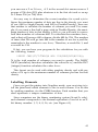
Labelling Elements
Once you put the printer into Graphics mode, your next step is to
tell the print head which elements to fire in each column. You do this
by sending numbers via the CHR$ function. Each number that you
send represents a unique combination of dots.
Since computers use the binary numbering system (0S and 1s only),
each element corresponds to the decimal equivalent of one bit in an 8bit binary number: 1, 2, 4, 8, 16, etc. (see Figure 6-l).
43
Figure 6-1. Labelling elements
Decimal sum
of the desired
pin pattern
Figure 6-2. Element combinations
44
The place values in a binary number are powers of two. Figure 6-2
shows how you use a decimal sum—74—to fire a particular pattern. If
you try adding several numbers together, you’ll see that with this system you get no duplicates. The number 6 represents elements 2 and 4
(since 2 + 4 = 6) and there is no other way to get 6 by adding powers
of two. This means that any combination of the eight elements adds
up to a unique decimal number that falls within the range 0 to 255.
With this labelling system, you fire the top element by sending
LPRINT CHR$(128). To fire the bottom graphics element, you send
LPRINT CHR$(1). If you want to fire only the top and bottom elements, you simply add 128 and 1, then send LPRINT CHR$(129). By
adding the appropriate label numbers together, you can fire any combination of elements you want.
Note: If your computer system cannot send ASCII codes above 127,
you will not be able to fire the top element.
A Graphics Program
Now that we have discussed how Dot Graphics works, the following program gives you an example of what you can do. This program
creates a series of space invaders. Type the program in exactly as you
see it.
10 WIDTH LPRINT 255
20 INPUT "GRAPHICS CODE (K, L)";CODE$
30 INPUT "n1 and n2 PLEASE";N1,N2
40 INPUT "HOW MANY GRAPHICS DATA";DCOUNT
50 DIM D(DCOUNT)
60 FOR J=1 TO DCOUNT
70 INPUT "DATA";D(J)
80 NEXT J
90 LPRINT CHR$(27);CODE$;CHR$(N1);CHR$(N2);
100 FOR L=1 TO (N1+N2*256)/DCOUNT
110 FOR K=1 TO DCOUNT
120 LPRINT CHR$(D(K));
130 NEXT K
140 NEXT L
150 END
When you RUN the program, it will first ask you to enter the control code that you want to use for dot graphics. Your choices are
<ESC> K or <ESC> L. Enter K to run the program in Single-Density.
45
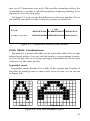
The width of one space invader in this program is 12-dot positions
(plus one blank space). This means that 13-dot positions are enough
data to describe a single invader. We will use a series of 20 invaders for
this program. This gives you a total of 260 (13 x 20) dot positions for
data.
To find n1 and n2, divide 260 by 256 and you get a quotient of 1 with
a remainder of 4. Enter 4 as the value for n,, and 1 as the value for n2.
Enter these values with a comma between them.
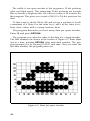
The program then asks you how many data per space invader.
Enter 13 and press RETURN.
The program now asks the order of the data for a single invader.
The data numbers are shown at the bottom of Figure 6-3. Enter them
one at a time, pressing RETURN after each data number. The program prompts you by showing DATA? each time. Once you enter the
last data number, the program prints out.
Figure 6-3. Data for space invader
46
Note: If you don’t understand how the numbers were determined,
refer to Figures 6-1 and 6-2.
It takes a while for your system to compute the data so be patient.
Your printout should look like this:
Run the program once more, but this time use Double-Density
mode. When the program asks you for a control code, enter L. Enter
the rest of the data exactly as you did with Single-Density mode. You
should achieve the following result.
If your printout does not look like this one, be sure you are entering
the correct values for n1 and n2. If the values are not correct, and more
data is sent to the printer than it was told to expect, it will interpret
values as character codes,
Graphics Programming Tips
The information in this section will provide you with a few elements to keep in mind when programming in graphics.
Line spacing
To print figures taller than 7 or 8 dots in Graphics mode, the print
head must make more than one pass. If you use the default 12-dot (1/6
inch) line spacing, the print head will leave gaps between the graphics
lines, just as it does between the text lines. To avoid such gaps in your
patterns, adjust the line spacing to 8-dot with ESCape”A”CHR$(8)
and print consecutive lines until the figure is complete.
ESCape “A”CHR$(n), where n represents n/72-inch, changes the
distance that a line feed covers to n dots. The ESCape “A”CHR$(n)
command sets the line spacing to n/72-inch if the n is any number
from 0 through 85. If n is between 85 and 128, the line spacing is
85/72-inch.
47
WIDTH statements
Many computer systems automatically insert a carriage return and
a line feed after every 80 characters. This insertion usually causes no
problem with text, but it can spoil your graphics. In the Graphics
mode, some systems insert the control codes after 120 columns, which
may be in the middle of a line.
You can usually prevent these unwanted control codes with a
WIDTH statement such as the one below:
WIDTH LPRINT 255
The format for your system may differ. Consult your computer’s documentation to find the correct format for your system. Then put a
WIDTH statement in one of the first lines of all your graphics programs. It is easier to put a WIDTH statement in all but the simplest of
your programs than to examine each one to see whether it needs such
a statement.
Semicolons and command placement
After the graphics command is issued, every number sent to the
printer is interpreted by the P-80 as a dot pattern and is printed on the
paper. Therefore, you must be careful where you put the graphics
command in your program, and you must not put another command
between the graphics command and the graphics data.
For example, suppose you want to print a 50-column graphics line
and you want to set the line spacing to o-dot for future additions to the
program. You might enter the following program:
20 LPRINT CHR$(27)"K"CHR$(50)CHR$(0)
30 LPRINT CHR$(27)"0"
40 FOR G=1 TO 50: LPRINT CHR$(74): NEXT G
This program has all the necessary elements. Line 20 has the command for Single-Density Graphics and specifies 50 columns. (Remember that you must use two CHR$ numbers to reserve columns even if
you only need the first one.) Line 30 has the correct command for
9-dot line spacing, and line 40 calls for the printing of a pin pattern 50
times.
Although this program has all the necessary elements, it will not
give you the printout of a single pattern that you want, as you can see
in the partial printout in Figure 6-4.
48
Figure 6-4. Result of incorrect program
Once the graphics mode is in effect, every number sent to the
printer is interpreted as a dot pattern and printed on the paper. Since
no semicolon appears at the end of line 20, the numbers 13 and 10the codes for carriage return and line feed-are sent to the printer after
CHR$(0), and interpreted as dot patterns.
Line 30, the command for 9-dot line spacing is also interpreted as a
dot pattern. Since no semicolon appears at the end of this line, the
numbers 13 and 10 are sent again and printed as pin patterns as well.
In line 40 nothing is sent to the printer until after the LPRINT. Then
the desired dot pattern-CHR$(74)-is finally sent. Again, since no
semicolon is after CHR$(74), 13 and 10 are sent each time the loop is
executed.
After the P-80 has received all the numbers that are reserved by the
graphics command-50 in this case-it leaves the Graphics mode and
resumes interpreting numbers in the normal way. Because the incorrect program has sent many extra numbers, mainly 10s and 13s, the 50
reserved columns are filled before the loop in line 30 has been executed
50 times. Therefore, during the last passes of the loop, the P-80 interprets CHR$(74) as the ASCI code for “J”. It prints a “J” and issues a
carriage return and line feed for each of the last 35 passes of the loop.
To make the program work correctly, put the line-spacing command in line 10, delete line 30, and add two semicolons: one at the end
of line 20 and one between CHR$(74) and the colon in line 40.
This program is explained in detail so that you remember two
important points about using the graphics command:
l
Use semicolons to prevent the P-80 from printing carriage return
and line feed codes as pin patterns.
49
l
Do not put any other commands between the graphics command
and its data.
We hope this example helps you identify errors if one of your own
programs gives you unexpected results.
50
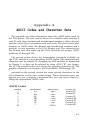
Appendix A
ASCII Codes and Character Sets
This appendix provides information about the ASCII codes used on
the P-80 printer. The first section shows the available codes between 0
and 32 with their decimal and hexadecimal numbers, abbreviations,
and the control keys associated with each code. The first section also
displays, in ASCII order, the decimal and hexadecimal numbers and a
printout of each character in the USA Roman font. The characters for
the Roman font that make up the USA character set occupy ASCII
positions 33 through 126.
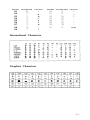
The second section shows the international characters available on
the P-80 and their corresponding ASCII codes. The international
characters can be selected by changing the DIP switches as mentioned
in Chapter 1, or they can be selected by using <ESC>“R” (see Appendix B). The second section also shows the graphics character set. The
graphics character set occupies ASCII positions 128 through 159.
Included in the second section are some special characters in the
USA character set that are worth noting. These characters may not
appear on your computer’s keyboard but you can access them by
using the appropriate ASCII code.
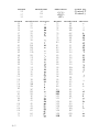
ASCII Codes
Decimal
9
10
12
13
14
15
18
Hexadecimal
Abbreviation
09
<HT>
0A
0C
0D
0E
0F
12
<LF>
<FF>
<CR>
<SO>
<SI>
<DC 2>
Control key
Control-I
Control-J
Control-L
Control-M
Control-N
Control-O
Control-R
A-1
Decimal
Hexadecimal
Abbreviation
20
27
32
14
1B
20
<DC4>
Decimal
33
34
35
36
37
38
39
40
41
42
43
44
45
46
47
48
49
50
51
52
53
54
55
56
57
58
59
60
61
62
63
64
65
66
67
68
69
70
71
A-2
Hexadecimal Character
21
22
23
24
25
26
27
28
29
2A
2B
2C
2D
2E
2F
30
31
32
33
34
35
36
37
38
39
3A
3B
3C
3D
3E
3F
40
41
42
43
44
45
46
47
Control key
Control-T
Control-)
<ESC>
<SP>
Decimal
72
73
74
75
76
77
78
79
80
81
82
83
84
85
86
87
88
89
90
91
92
93
94
95
96
97
98
99
100
101
102
103
104
105
106
107
108
109
110
Hexadecimal Character
48
49
4A
4B
4C
4D
4E
4F
50
51
52
53
54
55
56
57
58
59
5A
5B
5C
5D
5E
5F
60
61
62
63
64
65
66
67
68
69
6A
6B
6C
6D
6E
H
I
J
K
L
M
N
O
P
Q
R
S
T
U
V
W
X
Y
Z
[
\
]
a
b
c
d
e
f
g
h
i
j
k
l
m
n
Decimal
Hexadecimal
111
112
113
114
115
116
117
118
119
6F
70
71
72
73
74
75
76
77
Character
o
p
q
r
s
t
u
V
Decimal
Hexadecimal
Character
120
121
122
123
124
125
126
127
78
79
7A
7B
7C
7D
7E
7F
x
y
z
{
|
}
~
none
W
International Characters
Graphics Characters
A-3
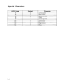
Special Characters
A-4
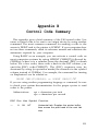
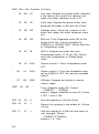
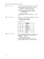
Appendix B
Control Code Summary
This appendix gives a brief summary of the P-80 control codes. You
cause a control code to be sent to an output device by using another
command. The most common command for sending a code to the
screen is PRINT and to the printer is LPRINT. If your computer does
not use these commands, check its reference manual and substitute the
statements required by your computer.
Using BASIC as an example, you can activate a control code on
most computer systems by using LPRINT CHR$(27) followed by
CHR$(n), where n is a number from the decimal (DEC) column
below. For a few codes, those with a dash in the ESC column, you
omit the (ESC) code-CHR$(27). The (ESC) sequence may be
shortened by using (in quotation marks) the character in the symbol
column instead of CHR$(n). For example, the command for turning
on Emphasized can be entered as:
LPRINT CHR$(27)CHR$(69) or LPRINT CHR$(27)"E"
If you are using another programming language or command, be sure
to check your system documentation for the proper syntax to send
codes to the printer.
Abbreviations:
cpi = characters per inch
cps = characters per second
ESC Dec Hex Symbol Function
—
9
09
HT
Horizontal tab. Empties the printer buffer,
then moves the print head to the next tab
stop.
B-l
ESC Dec Hex Symbol Function
-
10
0A
LF
Line feed. Empties the printer buffer, performs
a line feed at the current line spacing, and
resets the buffer character count to 0.
-
12
0C
FF
Form feed. Empties the printer buffer, then
advances the paper to the next top of form.
-
13
0D
CR
Carriage return. Prints the contents of the
buffer and resets the buffer character count
to 0.
-
14
0E
SO
Shift out. Turns Expanded mode ON for the
length of the line. Can be cancelled by
CHR$(20) or CHR$(27)“WO”. Works with Pica
or Compressed mode.
-
15
0F
SI
Shift in. Empties the buffer and turns
Compressed mode (17.16 cpi) ON. Cannot
work with Emphasized or Double-Strike
mode.
-
18
12
DC2
Device control 2. Turns Compressed mode
OFF
-
20
14
DC4
Device control 4. Turns the Expanded mode
set by CHR$(14) OFF Can also be cancelled
with LF
-
27
1B
ESC
ESCape. Prepares the printer to receive
control codes.
ESC
45
2D
-
Turns Underline mode ON. Format:
CHR$(27)” - “CHR$(n)
where n toggles Underline on and off: 0 turns
it OFF 1 turns it ON.
ESC 48
30
0
Sets line spacing to 1/8-inch (9-dot).
ESC 50
32
2
Returns line spacing to the default of 1/6-inch
(12-dot).
ESC 51
33
3
Sets line spacing to n/144-inch and stays on
until changed. Format:
CHR$(27)“3”CHR$(n)
where n = 0 - 255.
B-2
ESC Dec Hex Symbol Function
ESC 52 34 4
Turns Italic mode ON.
ESC 53 35 5
Turns Italic mode OFF
ESC 64 40 @
Reset Code, which resets the printer to its
power-up state, including resetting top of
form. Clears all text and control codes from
the print buffer.
ESC 65 41 A
Sets line spacing to n/72 inch (n-dot). Format:
CHR$(27)“A”CHR$(n)
where n = 0 - 127.
ESC 67 43 C
Sets the form length to n lines in the current
line spacing. The default is 66 lines. Also
resets top of form. Format:
CHR$(27)“C”CHR$(n)
where n = 1 - 127.
ESC 67 43 C
Sets the form length to n inches, regardless
of the current line spacing. The default is 11
inches. Also resets top of form. Format:
CHR$(27)“C”CHR$(0)CHR$(n).
where n = 1 - 22.
ESC 69 45 E
Turns Emphasized mode ON. Cannot mix with
Compressed mode or Double-Strike mode.
ESC 70 46
Turns Emphasized mode OFF
F
ESC 71 47 G
Turns Double-Strike mode ON. Cannot mix
with Emphasized and Condensed modes.
ESC 72 48 H
Turns Double-Strike mode OFF
ESC 75 4B K
Turns Single-Density Graphics mode ON.
Prints 480 dots per 8-inch line. Format:
CHR$(27)“K”CHR$(n 1)CHR$(n 2)
followed by n data numbers, where
n = total number of dot columns,
n1 = n MOD 256,
n2 = INT (n/256).
For example, to print 480 dots, n1 = 224,
n 2 = 1.
B-3
ESC Dec Hex Symbol Function
ESC 76 4C L
Turns Double-Density Graphics mode ON.
Prints 960 dots per 8-inch line. Format:
CHR$(27)”L”CHR$(n 1)CHR$(n 2)
followed by n data numbers, where
n = total number of dot columns,
n1 = n MOD 256,
n2 = INT (n/256).
For example, to print 960 dots, n1 = 192,
n 2 = 3.
ESC 82 52 R
Selects an international character set by its
country’s number. Format:
CHR$(27)“R”CHR$(n)
where n = 0 - 7.
ESC 87 57 W
Turns Expanded mode ON; stays ON until
turned OFF Cannot be turned off with
CHR$(20). Format:
CHR$(27)“W”CHR$(n)
where n toggles the mode on and off:
0 or 48 turns it OFF 1 or 49 turns it ON.
B-4
Appendix C
Control Codes by Function
This appendix shows the same control codes as Appendix B; they
are arranged by categories and by ASCII order within the categories.
Character Width (Pitch)
CHR$(5)
CHR$(18)
CHR$(14)
CHR$(20)
CHR$(27)“W0”
CHR$(27)"W1”
Turns Compressed Mode ON.
Turns Compressed Mode OFF.
Turns One-Line Expanded Mode ON.
Turns One-Line Expanded Mode OFF.
Turns either Expanded Mode OFF.
Turns Continuous Expanded Mode ON.
Character Weight
CHR$S(27)“E”
CHR$(27)“F”
CHR$(27)“G”
CHR$(27)“H”
Turns Emphasized Mode ON.
Turns Emphasized Mode OFF.
Turns Double-Strike Mode ON.
Turns Double-Strike Mode OFF.
Print Enhancement
CHR$(27)“-0”
CHR$(27)“-1”
Turns Underline Mode OFF.
Turns Underline Mode ON.
C-l
Mode and Character-Set Selection
Turns Italic Mode ON.
CHR$(27)“4”
Turns Italic Mode OFF.
CHR$(27)“5”
Reset Code.
CHR$(27)"@”
CHR$(27)“R” CHR$(n)
Selects an international character set.
Line Spacing
Sets line spacing to l/S-inch.
CHR$(27)“0”
Sets line spacing to 1/6-inch (default).
CHR$(27)“2”
CHR$(27)“A”CHR$(n)
Sets line spacing to n/72-inch.
CHR$(27)“3”CHR$(n)
Sets line spacing to n/l&inch.
Forms Control
CHR$(9) or CHR$(137)
Activates a horizontal tab.
Produces a form feed.
CHR$(12)
Produces a carriage return.
CHR$(13)
CHR$(27)“C”CHR$(0)CHR$(n)
Sets the form length in inches.
CHR$(27)“C”CHR$(n)
Sets the form length in lines.
Dot Graphics
CHR$(27)“K”CHR$(n 1)CHR$(n 2)
Turns Single-Density Graphics Mode ON.
CHR$(27)“L”CHR$(n 1)CHR$(n2)
Turns Double-Density Graphics Mode ON.
c-2
Appendix D
Using Your P-80
with the Geneva™ PX-8™
Since your P-80 is a portable printer, it is a suitable companion for
any portable computer. With the P-80, you can print anywhere, thus
eliminating the need to wait until you have access to a desktop printer.
The Geneva is one example of a portable computer. It comes with a
pre-installed utility ROM capsule with CP/M-80™ and a pre- installed
BASIC ROM capsule. Additional ROM capsules containing Portable
WordStar™, Portable Calc, and Portable Scheduler’” are also
included. Instructions on how to print data from each of these software applications can be found in their accompanying documentation. Check the index under printing for the appropriate pages.
P-80 and WordStar
To print the desired results from some of these programs such as
WordStar, some modifications may be necessary. For example, the
P-80 stops printing when no paper is in contact with the paper-out
sensor (a reed switch located on the paper guide).
The paper-out sensor keeps the printer from printing after the paper
has run out, but it also keeps you from printing page numbers near the
bottom of the page. To compensate for this, you can either change the
page length or footing margin, place your page numbers near the top
of the page, or omit the page numbers. All of these can be done by
using dot commands in WordStar. See Chapter 7 in your Geneva
Portable WordStar Reference Manual.
D-l
Note: If you do not use a dot command, or omit page numbers, as
described above, the P-80 stops printing near the bottom of the
page. Although printing has stopped, the printer and the computer remain in the print stage. To end your print session, in
WordStar, press the P to stop print and then Y to abandon
print.
If you are going to be using WordStar most of the time, you can
tape a business card or a small piece of paper over the paper-out sensor. Then you can easily print to the bottom of your page.
When you are using single-sheet paper and have more than one
page in a document, you will need to activate the print pause command. The print pause command keeps the printer from printing
without any paper and allows you to, change sheets. The print pause
command is one of the print options displayed when you press P to
print-from the main menu in WordStar. Select Y for yes for the printer
to pa&e between pages. You can also insert a print pause code in your
document. See Chapter 7 of your Geneva Portable WordStar Reference Manual. Be sure to line the top of your sheet of paper with the
serrated edge on the printer as the printer expects 66 print lines (the
default in WordStar).
If a particular function exists on WordStar, but not on the P-80, the
printer will ignore the command to execute this function. For example, if you want to print in Elite, the P-80 will ignore this command
since it does not have this capability. Before using print commands in
your software applications, check to see that they are available on the
P-80 by consulting Appendix C in this manual.
Connecting the Geneva to the P-80
The P-80 uses the RS-232C serial interface and is factory set at 4800
baud. This is the appropriate setting for use with the Geneva. Your
Geneva can be set to the RS-232C or serial interface using the CONFIG command. Consult your Geneva User’s Manual. RS-232C is the
factory setting for the Geneva.
You need Epson cable #723 to connect the Geneva to your P-80 as
shown in Figure D-l. When you plug the cable into your Geneva, be
sure you insert it into the serial port designated in the CONFIG command. If the designation is RS-232C, plug the cable into the serial port
marked RS-232C.
D-2
Figure D-l. Connecting the Geneva to the P-80
Be sure you have properly connected your printer and it is ON and
on-line before you begin to print. If the P-80 won’t respond to any of
the computer’s print commands, hold down CTRL and press STOP
on the Geneva. Then check to see that you have the proper serial port
connection, the cable is connected correctly, and the printer is ON and
on-line.
D-3
Appendix E
Specifications
of the P-80
Printing
Printing Method
Thermal transfer
Printing Direction
Unidirectional (left to right)
Paper feed speed
2 lines per second (at 1/6 inch/line)
Character Sets
96 Roman characters
96 Italic characters
32 Graphics characters
8 International character sets
Line Spacing
1/6 inch (default), 1/8 inch or programmable
in increments of 1/72 inch and 1/144 inch
E-l
Table E-1 Characters
Number
Pica
Pica
Pica
Pica
Pica
Pica
Expanded
Emphasized
Emphasized
Condensed
Condensed
Print
Character
pitch
speed
CPI
CPS
spacing
80
40
80
40
136
68
10
5
10
5
17 1/7
8 4/7
45
22.5
22.5
11.25
38.6
19.3
10
5
5
5
17 1/7
8 4/7
.083
.166
.091
,182
.043
.083
.096
.096
.096
.096
.096
.096
80
40
80
40
135
68
10
5
10
5
17 1/7
8 4/7
22.5
11.2
22.5
11.25
38.6
19.3
10
5
10
5
17 1/7
8 4/7
,110
.193
.118
.209
,079
,110
.096
.096
.096
.096
.096
,096
Columns
CPL
Expanded
Expanded
Italic
Italic Expanded
Italic Emphasized
Italic Emphasized
Expanded
italic Condensed
Italic Condensed
Expanded
CPL= characters per line
CPI = characters per inch
CPS = characters per second
Character
size (in)
Character
Of
Print mode
CPI
Width Height
Paper
Paper types
Single-sheet or roll paper, up to 8.5 inches
wide
Thermal or Standard
Printer
Dimensions
Height: 2½ inches (62.2 mm)
Width: 11¾ inches (297 mm)
Depth: 4¼ inches (107 mm)
Weight
2.4 lbs (1.1 kg)
Power required
Voltage: 4.8 VDC (TYP) 4 Ni-Cd batteries
Ni-Cd battery: Pen light (AA) size nominal
capacity: 500 mAh
Battery life: 300 recharging cycles possible
(avg.)
Power consumption: 3 W avg. during use AC
adapter (HOOCAA): 6V output DC 700 mA
E-2
Printing capability with fully charged batteries: 60,000 characters (approximately 30
pages on 8½ by 11 paper with 2,000 characters per page)
Environment
Temperature: 5°C to 35°C
Humidity: 10% to 80% RH
Ribbon
Cassette ribbon, black, model #8760
Ribbon life expectancy 40,OOO characters (approximately 20 pages
with 2,000 characters per page)
Printer MCBF
500,000 lines (excluding print head life)
Print head life
20 million characters
Buffer memory
240
bytes
Interface
The P-80 has an RS-232C serial interface
Specifications
Bit rate
Set with DIP switches on the back of the
printer
Synchronization
Asynchronous
Handshaking
With DTR signal
Logic Levels
Voltage
+3V to +18V
-3V to -18V
Data Format
Dip switch selectable
Logic Value
Space 0 (ON)
Mark 1 (OFF)
Interface Connector
Plug
6-pin DIN type
E-3
Interface Signals
E-4
Index
A
A4•Legal6
AC adapter 17-18
Arrows 6
ASCII (American Standard Code for Information Interchange) 27-30,
A-l
codes and graphics 39, A-3
codes and international characters A-3
codes and special characters A-4
codes listed for all characters A-2 -A-4
codes on the P-80 28
Automatic line feed 11
B
Baud rate 12
B56
Back cover 5
BASIC 30-31, 33, 39, 42, B-l
Battery 16-21
Battery holder cover 19-22
Battery replacement 19-22
Bold printing. See Double-Strike, Emphasized
C
Cable, connection of 13
Carriage return 28-29, B-2, C-2
Cassette, ribbon See Ribbon cassette
Characters, graphics See Graphics characters
Characters, international See International character set
Characters, specifications of E-2
CHR$29, 39
Codes. See ASCII codes; Control codes; ESCape
Compressed mode 34-35, 37, B-2, C-l
Computer, connecting printer to 12-13
Control codes 27, 28
listed by function C-l -C-2
listed by number B-l -B-4
See also specific modes and functions
Control key (CTRL) 28
Control panel 15
Covers, front and back 5
CTRL 28
Index-l
D
Density. See Graphics mode
Dimensions, of printer E-2
DIP switches 9-12
switch 1 10
switch 2 11
DENSITY switch 16
Dot
in dot graphics 39, 41, 45
matrix 33
positions 33
Double-Density graphics 42-43, 47, B-4, C-2
Double-Strike mode 36-37, B-3, C-l
Dress-Up Modes. See Underline mode; Italic mode
E
Emphasized mode 36-37, 40, B-3, C-l
Environment, of printer E-3
Epson computers. See Geneva PX-8
ESCape code (ESC) 29-30, B-2
Expanded mode 35, 37-40, B-2, B-4, C-l
F
FEED 5, 24
Foreign characters. See International characters
Form, length of B-3, C-2
Form feed B-2, C-2
FREE 5, 24,26
Front cover 5, 7
Function switches. See DIP switches
G
Geneva PX-8 39, D-l -D-3
connecting to printer, D-2
Graphics
characters 39-41
command placement 48, 50
densities in. See Graphics mode
dot 39, 41, 45
line 40
line spacing 47, 49
programming tips 47-50
program 45-47
semicolons 48-49
Index-2
width of 48
See also Graphics mode
Graphics mode 42, 47-48
Single-Density 42-43, 45, B-3, C-2
Double-Density 42-43, 47, B-4, C-2
H
Hinges 7
Holders. See Paper holders
Horizontal tab B-l, C-2
I
Indicators 15
Installation
battery 19-21
printer cable 12-13
ribbon cassette 7-9
Interface E-3
connector E-3
signals E-4
specifications E-3
International character set 10-11, A-l, A-3, B-4, C-2
INVOICE 6
Italic mode 36, 38, B-3, C-2
K
Knob. See Manual-feed knob
L
LEFT EDGE 6
Lever
lock 5, 24
paper-release 24
Lids. See Covers
Light, ON LINE 16
Line feed B-2
automatic 11
Line spacing B-2-B-3, C-2
LIST command 30
LPRINT. See PRINT
Loading paper 24-25
Lock lever. See Lever
LOCK 5
Index-3
M
Maintenance 22
Manual-feed knob 9, 25-26
Metal paper stand 6
Modes,
combining 33, 35-38
priorities 36
summary, table of 37
See also specific modes by name
0
Off line 16
ON LINE light 16
ON LINE switch 16-18
OPEN 5
Orange tab 7
P
Paper
coarse 24
loading 24
placement 24
roll paper 24, E-2
sizes 24
thermal 7, 23
types 23
widths 6
Paper control switches 16
PAPER FEED switch 16, 26
Paper guide 5-6
Paper holder 6
right 24
Paper-out sensor 17, D-l-D-2
Paper release lever. See Lever
PAPER STAND 6
metal 6
PAPER SURFACE switch 17, 24
Pica mode 34-35, 40
Pin combinations 44-45
Pin labels 43-44
Pitch 34-35
Plastic paper holder 6
left 6
right 6
Portable Calc D-l
Index-4
Portable Scheduler D-l
Portable WordStar 33, 37-38, D-l-D-2
POWER switch 16
PRINT command 30, B-l
Print head 9
and dot graphics, 41-43
life of E-3
Print modes 33, 36
See also specific print mode
Print typestyles D-2
Print width. See Characters, specifications of
Printer parts 3-4
Printer preparation 3
Priorities. See Modes, priorities
R
Reset code B-3
Ribbon cassette 7-9, 16, 23
installation 7
T
Technical specifications E-l-E-4
characters E-2
interface E-2-E-4
paper E-2
printer E-2-E-3
printing E-I
Temperature, of printer 22, E-3
Test. See Self-test
Typestyles chart D-2
U
Underline mode 30, 36, 38, B-2, C-l
W
Weight, of printer E-2
Width
See Characters, specifications of
statement 48
Index-6
ASCII Code Summary
Dec
0
1
2
3
4
5
6
7
8
9
10
11
12
13
14
15
16
17
l8
19
20
21
22
23
24
25
26
27
28
29
30
31
32
33
34
35
36
37
38
39
40
41
42
43
44
45
46
47
48
49
50
51
52
Hex
CHR
Dec
Hex
00
01
02
03
04
none
none
none
none
none
none
none
none
none
53
54
55
56
57
58
59
60
61
62
63
64
65
66
67
68
69
70
71
72
73
74
75
76
77
78
79
80
81
82
83
84
85
86
87
88
89
90
91
92
93
94
95
96
97
98
99
100
101
102
103
104
105
35
36
37
38
39
3A
3B
3C
3D
3E
3F
40
41
42
43
44
45
46
47
48
49
4A
4B
4C
4D
4E
4F
50
51
52
53
54
55
56
57
58
59
5A
5B
5C
5D
5E
5F
60
61
62
63
64
65
66
67
68
69
05
06
07
08
09
0A
0B
0C
0D
0E
OF
10
11
12
13
14
15
16
17
18
19
1A
1B
1C
ID
1E
IF
20
21
22
23
24
25
26
27
28
29
2A
2B
2C
2D
2E
2F
30
31
32
33
34
HT
LF
none
FF
CR
SO
SI
none
none
DC2
none
DC4
none
none
none
none
none
none
ESC
none
none
none
none
space
!
"
#
$
%
&
'
(
)
+
'
/
0
1
2
3
4
CHR
5
6
7
8
9
:
;
<
=
>
?
@
A
B
C
D
E
F
G
H
I
J
K
L
U
N
0
P
Q
R
S
T
U
V
W
X
Y
Z
[
\
]
^
Dec
106
107
108
109
110
111
112
113
114
115
116
117
118
119
120
121
122
123
124
125
126
127
128
129
130
131
132
133
134
135
136
137
138
139
140
141
142
143
144
145
146
147
148
149
150
151
152
153
154
155
156
157
158
159
Hex
6A
6B
6C
6D
6E
6F
70
71
72
73
74
75
76
77
78
79
7A
7B
7C
7D
7E
7F
80
81
a2
a3
a4
a5
86
a7
88
a9
8A
8B
8C
8D
8E
8F
90
91
92
93
94
95
96
97
98
99
9A
9B
9C
9D
9E
9F
CHR
j
k
International Characters
1
m
n
o
p
q
r
s
t
u
V
USA
FRANCE
GERMANY
U.K.
DENMARK
SWEDEN
ITALY
SPAIN
W
X
Y
z
{
|
}
~
none
Graphics Characters
Special Characters
Character Width (Pitch)
Turns Compressed Mode ON.
CHR$(15)
Turns Compressed Mode OFF.
CHR$(18)
Turns One-Line Expanded Mode ON.
CHR$(14)
Turns One-Line Expanded Mode OFF.
CHR$(20)
CHR!$(27)“W0”
Turns either Expanded Mode OFF.
CHR$(27)“Wl”
Turns Continuous Expanded Mode ON.
Character Weight
CHR$(27)“E”
CHR$(27)“F”
CHR$(27)“G”
CHRS(27)“H”
Turns
Turns
Turns
Turns
Emphasized Mode ON.
Emphasized Mode OFF.
Double-Strike Mode ON.
Double-Strike Mode OFF.
Print Enhancement
Turns Underline Mode OFF.
CHR$(27)“-0”
CHR$(27)“-1”
Turns Underline Mode ON.
Mode and Character-Set Selection
CHR$(27)“4”
Turns Italic Mode ON.
CHR!$(27)“5”
Turns Italic Mode OFF.
Reset Code.
CHR$(27)“@”
CHR$(27)“R” CHR$(n)
Selects an international character set.
Line Spacing
CHR$(27)“0”
Sets
CHR$(27)“2”
Sets
CHR$(27)“A”CHR$(n)
Sets
CHR$(27)“3”CHR$(n)
Sets
line spacing to l/8-inch.
line spacing to l/6-inch (default).
line spacing to n/72-inch.
line spacing to n/144-inch.
Forms Control
CHR$(9) or CHR$(137)
Activates a horizontal tab.
Produces a form feed.
CHR$(12)
Produces a carriage return.
CHR$( 13)
CHR$(27)“C”CHR$(0)CHR$(n)
Sets the form length in inches.
CHR$(27)“C”CHR$(n)
Sets the form length in lines.
Dot Graphics
CHR$(27)“K”CHR$(n 1)CHR$(n 2)
Turns Single-Density Graphics Mode ON.
CHR$(27)“L”CHR$(n 1)CHR$(n 2)
Turns Double-Density Graphics Mode ON.
EPSON AMERICA, INC.
LIMITED WARRANTY
Epson America, Inc. hereby warrants that it will repair or replace, at its option, any
part of the Epson product with which this warranty is enclosed which proves defective
by reason of improper workmanship and/or material, without charge for parts or
labor, for a period of one (1) year. This warranty period commences on the date of
original purchase by the buyer other than for purposes of resale, and this warranty
applies only if such original purchase by the buyer was made in the United States.
To obtain service under this warranty you must return your Epson product, properly packaged in its original container or an equivalent, to the nearest authorized
Epson Service Center or the Dealer from whom the product was purchased. Any
postage, insurance and shipping costs incurred in presenting or sending your Epson
product for service are your responsibility.
The Dealer’s original bill of sale or other satisfactory proof of the date of the original buyer purchase of your Epson product must be made available to obtain service
under this warranty.
This warranty applies only if your Epson product fails to function properly under
normal use and within the manufacturer’s specifications. Batteries, as well as optional
software packages (ROMs) not contained in the original container of your Epson
product, are excluded from coverage under this warranty. This warranty does not
apply if the Epson label or logo, or the rating label or serial number, has been removed
from your Epson product, or if, in the sole opinion of Epson, your Epson product has
been damaged by faulty or leaking batteries not supplied by Epson, or by accident,
misuse, neglect, or improper packing, shipping, modification or servicing, by other
than Epson or an authorized Epson Service Center.
SOME EPSON PRODUCTS HAVE A COMPARTMENT CONTAINING
STATIC-SENSITIVE ELECTRONIC CIRCUITRY. THIS COMPARTMENT IS
CLEARLY LABELED. DO NOT OPEN IT! THIS WARRANTY WILL BECOME
VOID IF YOU ATTEMPT TO MODIFY OR ADJUST ANY ROM OR OTHER PART
OR DEVICE IN SUCH A COMPARTMENT OR IF YOU ATTEMPT TO ADD OR
INSERT ANY ROM OR OTHER PART OR DEVICE. IF ANY OF THESE STEPS IS
REQUIRED, BRING YOUR EPSON PRODUCT TO AN AUTHORIZED EPSON
DEALER.
THE DURATION OF ANY IMPLIED WARRANTY OF MERCHANTABILITY,
FITNESS FOR A PARTICULAR PURPOSE, OR OTHERWISE, ON YOUR EPSON
PRODUCT SHALL BE LIMITED TO THE DURATION OF THE EXPRESS WARRANTY SET FORTH ABOVE. IN NO EVENT SHALL EPSON AMERICA, INC. OR
ITS AFFILIATES BE LIABLE FOR ANY LOSS, INCONVENIENCE OR DAMAGE
WHETHER DIRECT, INCIDENTAL, CONSEQUENTIAL OR OTHERWISE, OR
WHETHER CAUSED BY NEGLIGENCE OR OTHER FAULT RESULTING FROM
BREACH OF ANY EXPRESS OR IMPLIED WARRANTY OF MERCHANTABILITY, FITNESS FOR A PARTICULAR PURPOSE, OR OTHERWISE, WITH RESPECT TO YOUR EPSON PRODUCT, EXCEPT AS SET FORTH HEREIN. SOME
STATES DO NOT ALLOW LIMITATIONS ON HOW LONG AN IMPLIED WARRANTY LASTS AND SOME STATES DO NOT ALLOW THE EXCLUSION OR
LIMITATION OF INCIDENTAL OR CONSEQUENTIAL DAMAGES, SO THE
ABOVE LIMITATIONS AND EXCLUSIONS MAY NOT APPLY TO YOU.
You may request information on how to obtain service under this warranty by
contacting the Dealer from whom your Epson product was purchased, or by contacting Epson America, Inc. at the address printed below:
Epson America, Inc.
Service Division
23155 Kashiwa Court
Torrance, CA 90505
(213) 534-0360
This warranty gives you specific legal rights, and you may also have other rights
which vary from state to state.