1
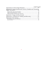
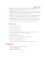
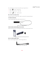
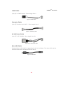
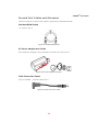
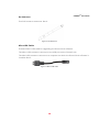
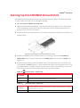
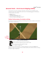
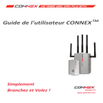
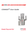
CONNEXTM User Guide 333 CONNEX TM User Guide Simply Plug-and-Fly! Version 1.0 www.amimon.com 1 CONNEXTM User Guide About This Guide This user guide describes how to setup and use the CONNEXTM wireless video link in order to transmit video from an aircraft. This user guide consists of the following chapters: • Chapter 1, Introducing CONNEX, page 9, introduces the CONNEX system, its components, its connectors, buttons and cables. • Chapter 2, Setting Up CONNEX, page 19, describes how to setup and connect the CONNEX Air Unit and Ground Unit. • Chapter 3, Using CONNEX, page 29, describes how to get started using the Air Unit and the Ground Unit. This chapter also describes the Ground Unit’s On Screen Display (OSD), how to set up multicasting and how to set up control of the aircraft’s camera gimbal from a gimbal remote control. • Chapter 4, CONNEX Management Application, page 37, describes how to configure and upgrade the CONNEX Air Unit and Ground Unit. For a quick summary of the essential steps for setting up quickly, you may refer to the CONNEX Quick Start Guide. Support and Contacting Information Support: www.AMIMON.com/support When contacting a support representative, make sure to have the Air Unit’s and Ground Unit’s serial number available. This number appears on the label on the bottom of each device. 2 CONNEXTM User Guide Important Notice Copyright © 2015 AMIMON. All rights reserved. All intellectual property rights are owned by AMIMON and protected by applicable copyright laws and international treaty provisions. All software/hardware is furnished under a license agreement. All other trademarks are the property of their respective owners. AMIMON reserves the right to make corrections, modifications, enhancements, improvements, and other changes to its products and services at any time and to discontinue any product or service without notice. Customers should obtain the latest relevant information before placing orders and should verify that such information is current and complete. All products are sold subject to AMIMON’s terms and conditions of sale supplied at the time of order acknowledgment. AMIMON warrants performance of its hardware products to the specifications applicable at the time of sale in accordance with AMIMON’s standard warranty. Testing and other quality control techniques are used to the extent AMIMON deems necessary to support this warranty. Except where mandated by government requirements, testing of all parameters of each product is not necessarily performed. AMIMON assumes no liability for applications assistance or customer product design. Customers are responsible for their products and applications using AMIMON components. To minimize the risks associated with customer products and applications, customers should provide adequate design and operating safeguards. AMIMON does not warrant or represent that any license, either express or implied, is granted under any AMIMON patent right, copyright, mask work right, or other AMIMON intellectual property right relating to any combination, machine, or process in which AMIMON products or services are used. Information published by AMIMON regarding third-party products or services does not constitute a license from AMIMON to use such products or services or a warranty or endorsement thereof. Use of such information may require a license from a third party under the patents or other intellectual property of the third party, or a license from AMIMON under the patents or other intellectual property of AMIMON. Reproduction of information in AMIMON data books or data sheets is permissible only if reproduction is without alteration and is accompanied by all associated warranties, conditions, limitations, and notices. Reproduction of this information with alteration is an unfair and deceptive business practice. AMIMON is not responsible or liable for such altered documentation. Resale of AMIMON products or services with statements different from or beyond the parameters stated by AMIMON for that product or service voids all express and any implied warranties for the associated AMIMON product or service and is an unfair and deceptive business practice. AMIMON is not responsible or liable for any such statements. All company and brand products and service names are trademarks or registered trademarks of their respective holders. CE1588 This equipment is in compliance with the essential requirements and other relevant provisions of Directive 1999/5/EC. Revision History Version Date Description 1.0 March 2015 Initial Release 3 Safety Instructions and Maintenance CONNEXTM User Guide All the instructions in this user guide must be adhered to when operating this equipment. Keep these instructions in a safe and accessible place for future use. Safety Symbols High Voltage Sign: Warns the user of the presence of uninsulated dangerous voltage within the product enclosure, which may be of sufficient magnitude to constitute a risk. General Warning Sign: Warns the user of the presence of important operating and maintenance (servicing) instructions in the product manual. Safety Instructions • Do not open the Air Unit or Ground Unit enclosures. There are no user-serviceable parts inside. Refer servicing to qualified service personnel only. The use of controls, adjustments or procedures other than those specified in this user guide may result in exposure to shock and/or electrical or mechanical hazards. • Do not immerse the units in water. • Do not block the air ventilation openings. • Always disconnect a unit’s power by pulling the mains plug. • Only clean with a dry cloth. • Keep powered on units at least 20 cm from your body. • Do not expose the units to moisture or excessive heat. Unit operating temperature is 32–104⁰F or 0−40⁰C. • Unplug the units during lightning storms or when not using them for long periods of time. • Only use the originally approved power supply adapter and only use it indoors. • Only use the supplied accessories or those recommended on the Amimon website. Accessories (including cables) must not be replaced, as they may affect performance or functionality or damage the unit. We highly recommend that you use the provided Amimon cables. If an alternate cable is used, make sure that it is of the highest quality. • Do not use the product if there is any physical damage to the enclosure. • It is normal for the product to become slightly hot during use. However, if the enclosure’s temperature becomes unbearable to touch, turn the product off and contact support. The internal fan of the Air Unit (transmitter) should work at all times when the power is on. • Do not let the product come into contact with corrosive materials. • Do not let the product come into contact with explosives, corrosive gas or nuclear weapons. • Do not let the product come into contact with fire. 4 CONNEXTM User Guide Potential Hazards The CONNEXTM Air Unit and Ground Unit contain HD wireless video modules devices that should be operated according to the same rules and limitations as expected from normal HD wireless video modules devices. Do not operate the units in an environment that may be susceptible to radio interference resulting in danger, specifically: • Areas where prohibited by the law: Follow any special rules and regulations and obey all signs and notices. Always ensure that the unit is turned off (the power switch is not lit) when instructed to do so or whenever it may cause interference or danger. • Where explosive atmospheres may be present: Do not operate the CONNEX units in any area where a potentially explosive atmosphere may exist. Sparks in such areas could cause an explosion or fire, resulting in bodily injury or even death. Be aware and comply with all signs and instructions. • It is not advisable to operate the CONNEX units while at a refueling point or service station: Users are reminded to observe restrictions on the use of radio equipment in fuel depots (fuel storage and distribution areas), chemical plants or where blasting operations are in progress. • Areas with a potentially explosive atmosphere are often, but not always, clearly marked: Potential locations can include gas stations, below deck on boats, chemical transfer or storage facilities, vehicles using liquefied petroleum gas (such as propane or butane), areas where the air contains chemicals or particles, such as grain, dust or metal powders and any other area where it would normally be advisable to turn off a vehicle’s engine. • Near medical and life support equipment: Do not operate the CONNEX units in any area where medical equipment, life support equipment or near any equipment that may be susceptible to any form of radio interference. In such areas, the host communications device must be turned off. The CONNEX unit may transmit signals that could interfere with this equipment. For more information, visit www.AMIMON.com. 5 CONNEXTM User Guide Contents About This Guide ................................................................................. 2 Support and Contacting Information ................................................................................ 2 Safety Instructions and Maintenance ............................................................................... 4 Contents................................................................................................................................ 6 Chapter 1, Introducing CONNEXTM .................................................... 9 About CONNEX ..................................................................................................................... 9 Key Features.............................................................................................................................. 10 In the Box ............................................................................................................................ 10 Air Unit (Transmitter) ............................................................................................................... 11 Ground Unit (Receiver) ............................................................................................................ 15 Chapter 2, Setting Up CONNEXTM .................................................... 19 Setting Up the CONNEX Air Unit ...................................................................................... 19 Connecting the Telemetry Port .............................................................................................. 23 Placement Guidelines – Air Unit Cable Antennas ................................................................ 23 Air Unit Antenna Mounting Accessories ............................................................................... 25 Setting Up the CONNEX Ground Unit .............................................................................. 26 Placement Guidelines – Ground Unit .................................................................................... 27 Chapter 3, Using CONNEXTM ............................................................. 29 Getting Started – Air Unit.................................................................................................. 29 Getting Started – Ground Unit.......................................................................................... 29 Ground Unit – On Screen Display (OSD) .......................................................................... 30 Default Information Overlaid on Video ................................................................................. 30 Additional Telemetry Information Overlaid on Video ......................................................... 31 Alert and System Messages .................................................................................................... 33 Multicasting to Multiple Ground Units ........................................................................... 34 Overview .................................................................................................................................... 34 Pairing Additional Ground Units with an Air Unit ................................................................ 34 Controlling the Aircraft Camera Gimbal ......................................................................... 36 Chapter 4, CONNEXTM Management Application .......................... 37 Overview ............................................................................................................................. 37 Installing the CONNEX Management Application ......................................................... 38 Connecting the Air Unit or Ground Unit to a Computer ............................................... 39 Upgrading the Air Unit or Ground Unit Firmware ......................................................... 40 Configuring the Link .......................................................................................................... 42 Checking the Ground Units Registered to an Air Unit ................................................... 44 Unregistering All Ground Units ........................................................................................ 45 6 CONNEXTM User Guide Appendix A, Technical Specifications ............................................. 47 Appendix B, Supported Remote Controls, Gimbals and Telemetry Flight Controllers ............................................................................... 48 Supported Air Unit Camera Gimbals ............................................................................... 48 Supported Gimbal Remote Controls ................................................................................ 48 Supported Flight Controllers for Telemetry ................................................................... 48 Appendix C, Supported Resolutions................................................ 49 Appendix D, Limitation of Liability and Warranty ........................ 50 Appendix E, FCC Caution................................................................... 51 FCC Radiation Exposure Statement ................................................................................. 51 About Amimon ................................................................................................................... 52 7 CONNEXTM User Guide Blank Page for Double-sided Printing 8 CONNEXTM User Guide Chapter 1, Introducing CONNEX TM This chapter introduces the CONNEX system, its components, its connectors, buttons and cables. About CONNEX Amimon’s CONNEX provides a high-end, high-performance wireless HD connection that can operate in challenging unmanned air or ground platforms under harsh conditions with zero latency, such as UAV/UGV. The small and lightweight CONNEX system transmits commercial, industrial, inspection and monitoring video in real time to its Ground Unit, which can be located up to 1,000 meters away. Figure 1: How CONNEX Works 9 CONNEXTM User Guide • Air Unit: The Air Unit is connected to an aircraft in order to capture video from the aircraft camera and to transmit it to up to four Ground Units simultaneously (multicast), thus creating a wireless video link. • Ground Unit: The Ground Unit connects to various types of monitors, video goggles or a portable video monitor via the HDMI port. This enables the pilot and/or camera operator to monitor the video transmitted from the Air Unit. • Pilot: The pilot can view the video on a monitor or wear video goggles connected to the Ground Unit. Flight control (telemetry) information from the aircraft is overlaid on the video. The pilot uses a remote flight controller to control the aircraft. • Camera Operator: The camera operator can hold a portable or PC video monitor on which the video can be viewed. The camera operator can use a gimbal remote control to control the aircraft camera’s gimbal through the S.BUS port of the Air Unit. Key Features • True full HD 1080P at 60fps • Up to 1,000 meter range (LOS) • Zero latency, real-time video • Extremely resilient 5GHz digital link • Automatic Frequency Selection (AFS) that fully complies with regulations and automatically selects the best free frequency available • Encrypted and secure • Sturdy design for harsh conditions • Built-in OSD view with embedded MAVLInk-based telemetry • Gimbal control over Futaba® S.BUS • Plug-and-Fly, ready to operate out of the box • DFS support enables multiple free channels, thus boosting robustness In the Box CONNEX is comprised of the following components: • Air Unit (Transmitter), page 11 • Ground Unit (Receiver), page 15 10 CONNEXTM User Guide Air Unit (Transmitter) Two Tx Cable Antenna Ports LEDs Reset Button Link Button HDMI IN Port USB Port Power S-BUS Port Telemetry Port Figure 2: Air Unit (Transmitter) Table 1: Air Unit Components S.BUS: Control port for the gimbal, which can be connected to a flight controller compatible with the S.BUS protocol or directly to an Air Unit receiver for the purpose of controlling the camera gimbal. S.BUS properties can be configured using the CONNEX Management application, which runs on the computer connected to the Ground Unit, as described in Chapter 4, CONNEXTM Management Application on page 37. Do not try to use the S.BUS signal for controlling the aircraft’s flight. This port should only be connected to the gimbal’s S.BUS of D.BUS port. Telemetry: Enables the display of flight control data from an aircraft that has a MAVLink-supported flight controller overlaid on an On Screen Display (OSD). Telemetry information includes flight mode, number of connected GPS satellites, speed, height and more. To receive telemetry data on Ground Unit, the Air Unit should be connected to the aircraft’s telemetry port. You may refer to Appendix B on page 48 for more information. Power Connector: 8-26-VDC voltage (3−6 cells). Micro USB Port: This port enables configuration and upgrade of the Air Unit software using the CONNEX Management application, as described in Chapter 4, CONNEXTM Management Application section on page 37. Mini HDMI IN: For receiving video from the camera. HDMI Connector Screw: For stabilizing the HDMI cable to the Air Unit. Link Button: The Air Unit is provided pre-paired (preregistered) with the Ground Unit that comes in the box. The Link button can be used to pair up to three additional Ground Units with the same Air Unit. You may refer to the Multicasting to Multiple Ground Units section on page 34 for a description of how to pair additional Ground Units with an Air Unit. Reset Button: Resets the Air Unit. Tx Cable Antenna Ports: Two lightweight 2dbi cable antenna ports. 11 CONNEXTM User Guide For a description of the Air Unit LEDs, you may refer to: • Table 3: Air Unit – Power LED • Table 4: Air Unit – Video LED • Table 5: Air Unit – Network LED Air Unit Accessories The box number in which each cable is provided is indicated below. Tx Cable Antennas Two flat lightweight 2dbi cable antennas. Box 2. Figure 3: Flat Tx Cable Antennas Cable Antenna Mounting Accessories Plastic accessories for mounting the antennas on the aircraft. Box 2. Figure 4: Cable Antenna Mounting Accessories Micro to Mini HDMI Cable Micro to Mini (Right Angled) – 50cm length. Box 1A. Figure 5: Micro to Mini HDMI Cable 12 CONNEXTM User Guide S-BUS Cable 5-pin JST to S-BUS female – 50cm length. Box 6. Figure 6: S-BUS Cable Telemetry Cable 6-pin JST female to 6-pin DF13 – 50cm length. Box 6. Figure 7: Telemetry Cable Air Unit Power Cable 4-pin JST to XT-60 Male – 50cm length. Box 1B. Figure 8: Air Unit Power Cable Micro USB Cable Standard Micro USB cable for upgrading the Air Unit software. The same cable can be used for both the Air and Ground Units. Box 6. Figure 9: USB Cable 13 CONNEXTM User Guide Mounting Plate For connecting the Air Unit to the aircraft. This item consists of two parts. Box 3. Figure 10: Mounting Plate Note: For information about additional accessories, go to www.AMIMON.com. 14 CONNEXTM User Guide Ground Unit (Receiver) The following shows both sides of the Ground Unit. Rx Antennas LEDs S.BUS Trainer Port USB Port Power Port Tripod Mount Hole Figure 11: Ground Unit (Receiver) – 1 HDMI Port Link Button OSD Button ON/Off Switch Figure 12: Ground Unit (Receiver) – 2 Table 2: Ground Unit Components Tripod Mount Hole: Enables you to connect the Ground Unit to a tripod. Connection to a tripod is optional. Power Port: 7-17VDC voltage. Micro USB Port: This port enables configuration and upgrade of the Ground Unit software using the CONNEX Management application, as described in Chapter 4, CONNEXTM Management Application section on page 37. S.BUS Trainer: This port can be connected to the Futaba Remote Control trainer port. This port enables you to remotely control the gimbal on the aircraft using the link between the Ground 15 CONNEXTM User Guide Unit and the Air Unit. The bit rate of this control can be configured in the S.BUS Rate field using the CONNEX Management application, as described in the Configuring the Link section on page 42. Five Rx Antennas Connectors: The five provided antennas must be screwed onto these connectors. On/Off Switch: Set this switch to On in order to power on the Ground Unit. OSD Button: Enables/disables the OSD display. The OSD display presents a screen of telemetry MAVLink-based information collected by the CONNEX system on the monitor connected to the Ground Unit, such as Air Unit flight parameters, height, direction, signal strength and so on. You may refer to the Ground Unit – On Screen Display (OSD) section on page 30 for more information. By default, OSD is enabled (displayed). Pressing this button disables OSD and pressing this button again redisplays it. Link Button: The CONNEX system supports up to four Ground Units per Air Unit. The Ground Unit is provided out-of-the-box to automatically search for and connect to the Air Unit that is provided in the same box. The Link button enables you to connect additional Ground Units to the same Air Unit. You may refer to the Multicasting to Multiple Ground Units section on page 34 for a description of this procedure. HDMI Port: Enables the display of the received video. Connect this port to a monitor’s HDMI port using the provided Standard HDMI cable. Battery Plate Screws: Four screws are provided on the bottom of the Ground Unit for connecting a battery plate. The battery plate is an optional accessory and is not included. It is available to be purchased from the Amimon’s website. For a description of the Air Unit LEDs, you may refer to: • Table 6: Ground Unit – Power LED • Table 7: Ground Unit – Video LED • Table 8: Ground Unit – Network LED 16 Ground Unit Cables and Antennas CONNEXTM User Guide The box number in which each cable is provided is indicated below. Standard HDMI Cable 1.2 meters. Box 7. Figure 13: Standard HDMI Cable AC Power Adapter and Cable Four different adapters are provided for indoor use only. Box 5. Figure 14: AC Power Adapter and Cable S.BUS Trainer Port Cable 3-pin to Futaba – 1meter cable. Box 6. Figure 15: S.BUS Trainer Port Cable 17 CONNEXTM User Guide Rx Antennas Five 2dbi screw-on antennas. Box 4. Figure 16: Rx Antennas Micro USB Cable Standard Micro USB cable for upgrading the Ground Unit software. The Micro USB connector connects to the USB port on the Ground Unit. The Mini USB connector connects to a computer on which the Ground Unit software is installed. Box 6. Figure 17: Micro USB Cable 18 CONNEXTM User Guide Chapter 2, Setting Up CONNEXTM This chapter describes how to setup and connect the CONNEX Air Unit and the CONNEX Ground Unit. This chapter contains the following sections: • Setting Up the CONNEX Air Unit, page 19 • Setting Up the CONNEX Ground Unit, page 26 Setting Up the CONNEX Air Unit Set up the CONNEX Air Unit (transmitter) and connect it to the aircraft, as described in this section. We highly recommend that you use the provided Amimon cables. If an alternate cable is used, make sure that it is of the highest quality. To set up the CONNEX Air Unit: 1 Assemble the Air Unit/aircraft mounting plate: If attaching the Air Unit to a flat surface on the aircraft, then perform the following: • Place the Air Unit in the center of the provided mounting plate on the side with the mounting plate bumps protruding. • Use screws or plastic ties to hold the Air Unit to the mounting plate. You can thread the plastic ties through any of the holes on the mounting plate. Figure 18: Attaching the Air Unit to the Mounting Plate 19 CONNEXTM User Guide If attaching the Air Unit to a bar on the aircraft, then perform the following before attaching the Air Unit to the mounting plate: • A clear plastic holder is provided to help attach the mounting plate to a bar or to the landing gear of the aircraft. The square plastic insert can be placed in the opening in the center of the mounting plate either horizontally or vertically according to how you want to position the mounting plate relative to the bar to which you are attaching it. • Insert the plastic holder into the opening in the square center of the mounting plate, as shown below: Square plastic insert for attaching the mounting plate to a bar Figure 19: Connecting the Mounting Plate to a Bar on the Aircraft 2 Attach the mounting plate (with the Air Unit attached to it as described above) to the aircraft using screws or plastic ties. Typically, it can be placed on the bottom of the aircraft. Make sure that the Air Unit’s ventilation openings are not obstructed. 3 IMPORTANT! For optimal performance, carefully read and then implement the guidelines provided in the Placement Guidelines – Air Unit Cable Antennas section on page 23. These guidelines describe the best mounting options for the Air Unit cable antenna options. Attach the Air Unit cable antenna mounting accessories to the aircraft. Make sure the mounting accessories are placed close enough to the Air Unit for the cable antennas to reach the Air Unit antennas port. 20 CONNEXTM User Guide 4 Connect the two Air Unit flat cable antennas to the two Air Unit cable antenna ports, as shown below: Figure 20: Connecting the Antennas to the Air Unit 5 Connect the provided Micro to Mini HDMI cable (Figure 5) from the HDMI IN port on the Air Unit to the camera. The right side of this cable (as shown in Figure 18) goes into the Air Unit HDMI IN port (Figure 2). The left side of this cable (as shown in Figure 18) goes into the aircraft’s camera. Figure 21: Connecting the Air Unit HDMI Cable – Box 1A Micro to Mini HDMI Close the HDMI Connector Screw (which is to the right of the HDMI IN port) to stabilize the connected HDMI cable to the Air Unit. 6 Connect the provided Air Unit Power cable (Figure 8) to the power port on the Air Unit. The right side of this cable (as shown in Figure 22) goes into the Air Unit power port labeled 8-26-VDC (Figure 2). The left side of this cable (as shown in Figure 22) goes to the battery. Figure 22: Connecting the Air Unit Power Cable – Box 1B 7 Connect the other end of the provided Air Unit power cable to the power source (battery). Use an 8-26-VDC voltage battery. Note that the Air Unit Power LED states of the Air Unit Power LED: lights up. The following describes the various 21 CONNEXTM User Guide Table 3: Air Unit – Power LED On (White) The Air Unit is powered on. Off No power is being supplied to the Air Unit. Blinks Quickly Indicates a system error. 8 The Air Unit automatically connects with the powered on Ground Units that are paired with this Air Unit. A connection is established between the Air and Ground Units regardless of whether video is transmitted on the wireless link, as follows: If video is transmitting, then the Ground Units display the video. If video is not transmitting, then the Ground Units display the message: Video signal not detected upon linking to the Air Unit. The Air Unit’s video and transmission status is indicated by its LEDs, as described below: Table 4: Air Unit – Video LED On (White) The video signal from the camera is locked, meaning that it is being correctly received by the Air Unit from the camera. Off The video from the camera is not locked, meaning that the Air Unit is not receiving the video from the camera. Blinks Quickly The Air Unit is powered down or the camera is transmitting a video resolution that is not supported by the Air Unit. Table 5: Air Unit – Network LED On (White) A link has been established to the Ground Unit, meaning that video is being transmitted to it. Off The Air Unit is not broadcasting because it has not recognized any Ground Units with which it was paired previously. Blinks Quickly The Air Unit is pairing with a Ground Unit or the Air Unit has gone out of range of the Ground Unit and is searching for it. Blinks Slowly The Air Unit is establishing a link with a Ground Unit. Blinks Very Slowly The Air Unit is searching for an available frequency on which to transmit. Note: This may take up to 70 seconds when working outdoors in Japan. 9 [Optional] To display information received from the aircraft’s flight controller overlaid on the video on the Ground Unit monitor, you may refer to the Connecting the Telemetry Port section on the following page. 22 CONNEXTM User Guide Connecting the Telemetry Port The following describes how to connect the Air Unit Telemetry port to the aircraft’s flight controller so that the Ground Unit monitor can display information received from the aircraft’s flight controller overlaid on the video, such as flight mode, number of connected GPS satellites, speed, height, orientation and more. To connect the Telemetry port: 1 Connect the Air Unit Telemetry port to the aircraft using the provided Air Unit Telemetry cable (Figure 7). The right side of this cable goes into the Air Unit Telemetry port (Figure 2). The left side of this cable goes into the Telemetry port of the flight controller on the aircraft. Figure 23: Connecting the Air Unit Telemetry Cable – Box 6 Note: Not all flight controllers are supported. You may refer to Appendix B on page 48 for a list of the supported flight controllers. Placement Guidelines – Air Unit Cable Antennas The following describes the mandatory requirements and the best practices for optional placement of the Air Unit vertical cable antennas. • Antennas Must Face the Ground: Both Air Unit cable antennas must be placed on the aircraft so that the antennas are pointing to the ground (vertical) when the aircraft is in flight. For example, as shown below: Vertical Antenna Vertical Antenna Figure 24: Antennas Must Be Placed so That They Point to the Ground • Avoid Obstacles between the Antennas and the Ground Unit: Place the Air Unit cable antennas as low as possible on the aircraft in order to avoid line of sight obstacles between the antennas and the Ground Unit while the aircraft is flying. • Avoid Interference: Place the Air Unit cable antennas as far away as possible from other transceiver devices on the aircraft, especially from a transmitter in the 5 GHz band. 23 CONNEXTM User Guide • Avoid Proximity to Metal Objects: The antennas must be at least 7 cm away from any metal object, such as the landing gear or a battery. For example do not tie the antenna directly onto the landing gear even if it is made of carbon. The mounting accessories enable you to attach the antennas while leaving the required distance. • Place the Antennas so That They Are Facing Outwards: Do not place the antennas facing the inside of the aircraft structure. • Place the Antennas so That They Are Still Facing the Ground When the Aircraft Takes Flight • Place the Antenna so That They Are Vertical (Pointing to the Ground), but Are Perpendicular: The following diagrams show two optimal placement options in which both antennas are facing different directions (perpendicular), achieving a 90° angle between them. Figure 25: Two Optimal Placement Examples Note: In order to achieve optimal transmission, you must also follow the Ground Unit placement requirements described in the Placement Guidelines – Ground Unit section on page 27. 24 Air Unit Antenna Mounting Accessories CONNEXTM User Guide The Air Unit antenna mounting accessories provide a variety of options for attaching the two provided flat cable antennas to the aircraft so that they are pointing the towards the ground (vertical). Antenna Mounting Screw Antenna Clamp Antenna Cable Antenna Mounting Piece Antenna Figure 26: Air Unit Cable Antenna Mounting Accessory – With Flat Cable Antenna – Box 2 Plastic ties can be threaded through here to attach this to the aircraft Aircraft leg/bar is here Figure 27: Front and Back of the Antenna Mount Piece This Antenna Clamp attaches to the rotary on the Antenna Mount Piece (shown above) using the provided screw. The Antenna Clamp has two holes through which you can insert the screw to attach it to the Antenna Mount Piece according to the direction you would like the antenna to point. Once the Antenna Clamp is connected to the Antenna Mount you can rotate it in the direction that you require the antenna to point, as shown below: Figure 28: Rotating the Antenna Clamp versus the Antenna Mount Piece 25 Setting Up the CONNEX Ground Unit CONNEXTM User Guide We highly recommend that you use the provided Amimon cables. If an alternate cable is used, make sure that it is of the highest quality. To set up the CONNEX Ground Unit: 1 Refer to the Placement Guidelines – Ground Unit section on page 27 for a description of the mandatory requirements and the best practices for optional placement of the Ground Unit and its antennas. 2 Screw on the five provided antennas to the five Ground Unit antenna connectors, as shown below: Figure 29: Connecting the Ground Unit Antennas – Box 4 3 Enable the display of the received video by connecting the provided Standard HDMI cable (Box 7) from the Ground Unit HDMI port to the monitor’s HDMI port (Figure 11). 4 Connect the provided power AC adapter (Box 5) to the power port on the Ground Unit labeled 7-17-VDC (Figure 11) and connect the other end to a power source. The provided power AC adapter should only be used in doors. The objective is to see all three LEDs on the Ground Unit light up (On), as described below. Table 6: Ground Unit – Power LED On (White) The Ground Unit is powered On and the unit’s On/Off switch (Figure 11) is on. Off No power is being supplied to the Ground Unit. Blinks Quickly Indicates a system error. Table 7: Ground Unit – Video LED On (Blue) The video signal from the Ground Unit is locked, meaning that it is being received from the Air Unit. Off The Ground Unit is powered down. 26 CONNEXTM User Guide Table 8: Ground Unit – Network LED On (Blue) A link has been established to the Air Unit, meaning that the Ground Unit is receiving video transmission from the Air Unit. The Network LED displays one of three colors to indicate the strength of the signal received by the Ground Unit, as follows: • Red: Poor • Green: Fair • Blue: Excellent Off No paired devices, meaning that the Air Unit is powered down or the Ground Unit is not paired with any Air Units. Blinks Quickly The Ground Unit is pairing with an Air Unit or the Air Unit has gone out of range of the Ground Unit, which is searching for it. Blinks Slowly The Ground Unit is searching for an Air Unit with which to establish a link. Placement Guidelines – Ground Unit The following describes the mandatory requirements and the best practices for optional placement of the Ground Unit and its antennas. • Place the Ground Unit as High as Possible: Place the Ground Unit on a tripod, pole or table so that it is as high as can be. A height of 2 meters is optimal. • Place the Ground Unit Antennas Facing the Air Unit: Place the Ground Unit so that its antennas are facing upwards in the general direction in which the aircraft will be flying. The five Ground Unit antennas can be placed as if the Ground Unit and its antennas are an open hand with the palm facing the aircraft, as shown below: Figure 30: Ground Unit Antennas Facing the Aircraft Like an Open Palm • Avoid Interference: Place the Ground Unit cable antennas as far away as possible from other transceiver devices, especially from a transmitter in the 5 GHz band. 27 CONNEXTM User Guide Blank Page for Double-sided Printing 28 CONNEXTM User Guide Chapter 3, Using CONNEX TM This chapter describes how to get started using the Air Unit and the Ground Unit. This chapter also describes the Ground Unit’s On Screen Display (OSD), how to set up multicasting and how to set up control of the aircraft’s camera gimbal from a gimbal remote control. Getting Started – Air Unit The Air and Ground Units provided in the same box are preconfigured to automatically search for and connect to each other. To get started with the Air Unit: 1 Set up the Air Unit, as described in the Setting Up the CONNEX Air Unit section on page 19. 2 The Air Unit can be configured to transmit video downlink to up to three additional Ground Units, as described in the Multicasting to Multiple Ground Units section on page 34. Getting Started – Ground Unit The Air and Ground Units provided in the same box are preconfigured to automatically search for and connect to each other. To get started with the Ground Unit: 1 Set up the Ground Unit, as described in the Setting Up the CONNEX Ground Unit section on page 26. The monitor connected to the Ground Unit then automatically displays video and an overlay of information received from the Air Unit, as described in the Ground Unit – On Screen Display (OSD) section on page 30. 29 CONNEXTM User Guide Ground Unit – On Screen Display (OSD) The Ground Unit monitor displays information collected by the CONNEX system overlaid on the video received from the Air Unit. The following types of information can be overlaid on the video: • Default, below • Telemetry [Optional], page 31 • Alerts and System Messages, page 33 Default Information Overlaid on Video By default, the Ground Unit displays the following information overlaid on the bottom of the video in a black strip: Default information overlay on video Figure 31: OSD ON – Default View • • • • : Distance of the Air Unit from the Ground Unit : Video resolution captured by the aircraft camera : Air Unit to Ground Unit video signal strength : Air Unit power voltage level By default, this OSD information is enabled (displayed). Pressing the OSD button (shown in Table 2) on the Ground Unit disables (hides) this OSD information. Pressing this button again redisplays it. 30 CONNEXTM User Guide Additional Telemetry Information Overlaid on Video Additional telemetry information can be overlaid on the video received from the aircraft’s flight controller. This information appears in a black strip on the top of the video, as shown below: Telemetry information overlay on video Figure 32: OSD View – With Additional Telemetry Information H: Aircraft Height. VS: Vertical Speed. GS: Ground Speed. : Flight Mode. The following standard 4-character Arducopter flight modes may be displayed: Table 9: Flight Modes Flight Mode Description STBL ARCO ALTH AUTO GUID LOIT RTL CIRC POS LAND DRFT Stabilize Arco Alt Hold Auto Guided Loiter RTL Circle Position Land Drift 31 SPRT CONNEXTM User Guide Sport : Number of Connected GPS Satellites. : Aircraft Battery Charge. This additional information is displayed when: • The aircraft has a MAVLink-based flight controller. • The Air Unit Telemetry port is connected to the aircraft’s flight controller, as described in the Connecting the Telemetry Port section on page 23. • The OSD button (shown in Table 2) on the Ground Unit is set to enable the display of flight control (Telemetry) information. When the Air Unit receives valid Telemetry MAVLink messages from the aircraft flight controller, these messages are transmitted to the Ground Unit, which displays the additional Telemetry information on the OSD. This may require a few seconds to take effect. You may refer to Appendix B on page 48 for a list of the supported flight controllers. To display OSD information: • While all three LEDs on the Ground Unit are lit, press the OSD button on the Ground Unit (Figure 11). The following is an example of the OSD View: Figure 33: OSD View – with Telemetry Information 32 Alert and System Messages CONNEXTM User Guide The following describes the messages that may appear on the monitor connected to the Ground Unit HDMI port. Alert Messages – Overlaid on Video during Link These alert messages may be displayed on top of the live video. Table 10: Alert Messages Out of Range A link still exists, but the video signal has been lost. This message is displayed regardless of the OSD button position. Approached Range Limit Is displayed for 30 seconds, from the moment the Air Unit has been detected as out of range until the Out of Range warning is displayed. This message represents a warning that the video signal is about to be lost. We recommend flying the aircraft back within the range of the Ground Unit. When the aircraft is within range, the video signal is automatically reacquired. This message is only displayed if the OSD button enables OSD display. Video Signal Not Detected A link has been established between the Air Unit and the Ground Unit, but no video signal has been detected. This message is displayed regardless of the OSD button position. System Messages – No Link These system messages may be displayed when no live video is displayed. Table 11: System Messages (in Link) Searching for Air Unit This message is displayed until a link is established. This may occur when the Air Unit is out of range, unavailable or has removed the Ground Unit from its list of paired devices. Starting Pairing Process Press OK to continue. Pairing in Progress Is displayed while the Air Unit is pairing with a Ground Unit. 33 CONNEXTM User Guide Multicasting to Multiple Ground Units Overview A single Air Unit can transmit video downlink to up to four Ground Units. This is called multicasting. The following procedure describes how to pair an additional Ground Unit with the same Air Unit. Note: The Air and Ground Units provided in the same box are preconfigured to automatically search for and connect to each other. Therefore, there is no need to perform this procedure on the Air Unit / Ground Unit provided in the same box. Note: Controlling the Air Unit's camera gimbal is not supported when multicasting to more than two Ground Units. Pairing Additional Ground Units with an Air Unit To pair an additional Ground Unit with an Air Unit: 1 Set up the additional Ground Unit, as described in the Setting Up the CONNEX Air Unit section on page 26. The Ground Unit must be placed between one and 10 meters from the Air Unit. Each Ground Unit must be placed at least a few meters away from other Ground Units in order to enable optimal reception. The following message is then displayed on the monitor connected to the Ground Unit’s HDMI port (Figure 11). Ground Unit not registered to Air Unit 2 Press and hold the Link button (Figure 11) on the Ground Unit (for approximately five seconds) until its Network LED starts blinking. The following message is displayed on the monitor connected to the Ground Unit: Please activate registration on Air Unit 3 Power on the Air Unit with which to pair this Ground Unit. This step assumes that the Air Unit has already been set up, as described in the Setting Up the CONNEX Air Unit section on page 19. Press the Air Unit’s Link button for five seconds until the Network LED starts blinking. After the LED begins blinking, the following message is displayed on the monitor connected to the Ground Unit. Air Unit detected. Please press the Link button. 34 CONNEXTM User Guide 4 Press and hold the Link button on the Ground Unit. The following message is then displayed: Pairing in progress After a while, the monitor connected to the Ground Unit should display the video received from the Air Unit, as described in the Ground Unit – On Screen Display (OSD) section on page 30. Note: If a black screen is displayed (as shown below), then check that the camera on the aircraft is operating. To see a list of Ground Units with which an Air Unit is currently paired and connected: You may refer to the Checking the Ground Units Registered to an Air Unit section on page 44. To clear all the Ground Units with which an Air Unit is paired: You may refer to the Unregistering All Ground Units section on page 45. 35 CONNEXTM User Guide Controlling the Aircraft Camera Gimbal The CONNEX Gimbal Control feature enables an operator on the ground to control the aircraft’s camera gimbal using a Futaba remote control over the video uplink channel. Only gimbals that can input S.BUS are supported. Gimbal control is supported for up to 1 Km. This feature can only be used when an Air Unit is paired with a single Ground Unit. Verify that this is the case , as described in the Checking the Ground Units Registered to an Air Unit section on page 44 before proceeding with the instructions below. To enable the CONNEX Gimbal Control feature: 1 Connect the Air Unit S.BUS port to the S.BUS or D.BUS port on the camera’s gimbal using the provided S.BUS cable (Figure 6). The right side of this cable goes into the Air Unit S.BUS port (Figure 2). The left side of this cable goes into the gimbal controller (GCU) on the aircraft. Figure 34: Connecting the Air Unit S-BUS Cable – Box 6 2 Ensure that the Futaba remote control is configured to output S.BUS on its Trainer port. Configuration is usually performed by setting the number of output channels to 16. 3 Connect the Futaba gimbal remote control’s Trainer port to the Ground Unit’s S.BUS Trainer (Figure 15) port using the S.BUS Trainer Port cable. 4 The default gimbal command transmission bit rate is FASSTest 12CH Mode (6.3m sec). If this bit rate is not supported by the gimbal controller, then use the CONNEX Management application to configure the S.BUS Bit Rate manually, as described in the Configuring the Link section on page 42. The Ground Unit automatically detects the S.BUS and transmits the gimbal commands over the wireless return channel to the Air Unit’s S.BUS port. You may refer Appendix B on page 48 for a list of supported remote controls and gimbals. 36 TM CONNEXTM User Guide Chapter 4, CONNEX Management Application This chapter describes how to configure and upgrade the CONNEX Air Unit and Ground Unit. Overview The Air Unit and the Ground Unit come preconfigured to communicate with each other. If needed, you can reconfigure the wireless video datalink by connecting the Air Unit to a PC and using the CONNEX Management application, as described in the Configuring the Link section on page 42. The Air Unit and the Ground Unit come preinstalled with the latest firmware version. If needed, you can upgrade the firmware of each, as described in the Upgrading the Air Unit or Ground Unit Firmware section on page 40. To use the CONNEX Management application: 1 Install the CONNEX Management application, as described in the Installing the CONNEX Management Application section on page 38. 2 Connect the Air Unit or Ground Unit to a computer, as described in the Connecting the Air Unit or Ground Unit to a Computer section on page 39. Note: Only a single CONNEX Air Unit or CONNEX Ground Unit can be connected to the CONNEX Management application at a time. 37 Installing the CONNEX Management Application CONNEXTM User Guide This application can run on a standard computer running Windows 7 and up. To install the CONNEX Management application: 1 Download the latest version from the Amimon website www.AMIMON.com/connex/management to a computer connected to a Ground Unit. 2 Run the installation file and follow the displayed instructions to install the CONNEX Management application. 3 Launch the application by double-clicking its desktop icon. The following window displays: Figure 35: Upgrading the Air Unit (shown on left) or Ground Unit (shown on right) The current version of the CONNEX Management application is displayed in the top left corner of the window. To upgrade the CONNEX Management application: • Download the latest version from the Amimon website and reinstall it, as described above. 38 CONNEXTM User Guide Connecting the Air Unit or Ground Unit to a Computer The Air Unit or Ground Unit must be connected to a computer on which the CONNEX Management application is installed in order to configure or upgrade that unit. To connect the Air Unit or Ground Unit to a computer: • Connect the Micro USB cable (Box 6) to the Air Unit’s or Ground Unit’s USB port (Figure 11). Figure 36: Connecting the Ground Unit to PC USB Cable – Box 6 If you launch the CONNEX Management application before connecting an Air Unit or Ground Unit to the computer, then the following message is displayed. Connect the unit, as described above. Figure 37: Connect the Unit Using a USB Cable 39 CONNEXTM User Guide Upgrading the Air Unit or Ground Unit Firmware Upgrading the Air Unit or Ground Unit firmware does not affect the settings of the wireless video downlink. To upgrade the Air Unit or Ground Unit firmware: 1 Make sure that the computer on which the CONNEX Management application is installed is connected to the Internet and is connected to the Air Unit/Ground Unit via a Micro USB cable. 2 Launch the CONNEX Management application by double-clicking its desktop icon. The following shows the window displayed on the Air Unit (on the left) and on the Ground Unit (on the right). The Software Upgrade tab is selected by default. This is the only tab that appears for the Ground Unit. Figure 38: Upgrading the Air Unit (shown on left) or Ground Unit (shown on right) The following describes the options in this window: Module: Specifies whether the connected unit is an Air Unit (Tx) or a Ground Unit (Rx). SW Version: Specifies the version of the firmware currently installed on the unit. SN / MAC ID: Specifies the unique identifiers of this unit: Serial number and MAC ID. Upgrade Button: The application automatically verifies with Amimon servers whether the latest firmware version of the connected unit is already installed. If the latest version is not installed, then the Upgrade button is active. 40 CONNEXTM User Guide 3 Click the Upgrade button. The latest software version is automatically downloaded from the Amimon website and installed on the connected unit. The bottom of the window displays the progress of the upgrade and lists the processes as they are performed, as shown below: Figure 39: Upgrading a Unit 4 If you upgrade an Air Unit, then you must upgrade all the Ground Units registered to it. We highly recommend that you only start the upgrade process after the Air Unit and its Ground Units have been collected and are placed next to the computer. An Air Unit and a Ground Unit that have different software versions may not communicate with each other. 41 CONNEXTM User Guide Configuring the Link The following describes how to configure the link between an Air Unit and the Ground Units. This procedure is performed on an Air Unit only. Link Mode S.BUS Rate Spectrum per Region Figure 40: Link Configuration To configure the link: 1 Make sure that the computer on which the CONNEX Management application is installed is connected to the Air Unit via a Micro USB cable and is connected to the Internet. 2 Launch the CONNEX Management application by double-clicking its desktop icon. 3 Select the Link Configuration tab. 4 In the Link Mode field, select the bandwidth channel mode, as follows: Optimized Quality (40 MHz): This is the default option. It provides the best quality. This is the only option that can be used with 1080P60 video resolution. Range Boost (20 MHz): Use this mode when a long range link is required (up to 1 KM). This mode enables higher stability, but only supports lower resolutions on the video link. 42 CONNEXTM User Guide 5 The SBUS Rate field specifies the data rate of the S.BUS link between the Ground Unit and the Air Unit that controls the Air Unit’s camera gimbal. CONNEX configures the data rate of the S.BUS remote control to be 6.3mSec (FASSTest 12CH) by default. You can select one of the following S.BUS Rate modes: Auto: 15m sec – FASSTest 18CH or T-FHSS Mode. The S.BUS rate is received and sampled from the remote control trainer port. The Air Unit then automatically outputs the same S.BUS rate. 6.3m sec – FASSTest 12CH Mode 6 The Spectrum per Region dropdown menu appears for CONNEX units used in Europe and Japan. This dropdown menu provides different options for your selection, as follows: In Europe, select either 5.8 GHz, 25mW or 5 GHz, 200mW, Ground use. In Japan, select either Indoor or Outdoor. Make sure that you select the frequency setting that complies with the local RF regulations in the region in which you are operating. 7 Click the Update button to apply the configured changes to the Air Unit. This affects how the Air Unit communicates with all the Ground Units with which it is registered, meaning those that are listed in the Registered Receivers list on the bottom right of the window. 43 CONNEXTM User Guide Checking the Ground Units Registered to an Air Unit To see which Ground Units are registered to an Air Unit: 1 Make sure that the computer on which the CONNEX Management application is installed is connected to the Air Unit via a Micro USB cable. 2 Launch the CONNEX Management application by double-clicking its desktop icon. 3 Click the Link Configuration tab. 4 The bottom right of the window displays a list of the MAC IDs of the Ground Units registered with this Air Unit, as shown below: Ground Units Registered to the Air Unit Figure 41: Registered Receivers The MAC ID of a specific Ground Unit can be seen using the CONNEX Management application as described on page 40. 44 Unregistering All Ground Units CONNEXTM User Guide Note: There is no option to unregister one Ground Unit at a time. To unregister all Ground Units from a specific Air Unit: 1 Make sure that the computer on which the CONNEX Management application is installed is connected to the Internet and is connected to the Air Unit via a Micro USB cable. 2 Launch the CONNEX Management application by double-clicking its desktop icon. 3 Click the Link Configuration tab. The bottom right of the window displays a list of Ground Units registered with this Air Unit, as shown below: Figure 42: Unregistering Ground Units 4 Click the Unregister all receivers button. For information about registering, you may refer to the Multicasting to Multiple Ground Units section on page 34. 45 CONNEXTM User Guide Blank Page for Double-sided Printing 46 CONNEXTM User Guide Appendix A, Technical Specifications Table 14: CONNEX Technical Specifications Transmission Distance Outdoor Up to 1,000m/3,000 ft. (LoS) Transmission Delay Zero [Less than 1 msec.] Radio Frequency 5.1-5.8 GHz, 17 channels Channel Selection Automatic frequency selection [AFS] Video Formats 60/59.94, 1080p/50, 1080i/60, 1080i/50, 30/29.97, 24/23.98, 60/59.94, 720p/50, 480i/60, 576i/50 Multicast Mode Up to 4 receivers with no delay or quality degradation. [Requiring extra Ground Unit(s)] OSD Support MAVLink Telemetry based Encryption AES-128 & RSA 1024 for key exchange Operating Temperature 0-45o Celsius Regulation CE, FCC, MIC Air Unit Ground Unit Video Interface Mini HDMI HDMI (Type A) Antenna Connectors MMCX (x2) SMA (x5) Power Connector 4-pins DC round Power Input 8-26V (3S-6S) 7-19V Dimensions (mm) 103 x 63.6 x 15.6 129 x 89 x 20 Weight 120 grams 290 grams 47 CONNEXTM User Guide Appendix B, Supported Remote Controls, Gimbals and Telemetry Flight Controllers The following lists the Air Unit camera gimbals and the remote controls that are supported by CONNEX. Supported Air Unit Camera Gimbals DJI – Zenmuse Z15 • • • • • • Zenmuse Z15-GH4 (HD) –, support S.BUS 6.3ms mode only Zenmuse Z15-GH3 Zenmuse Z15-BMPCC Zenmuse Z15-5D Zenmuse Z15-5D III (HD) Zenmuse Z15 Features Tarot Gimbal • Tarot T-2D Supported Gimbal Remote Controls Futaba • • • • 14GS FX22 18MZ FX32 Supported Flight Controllers for Telemetry • 3DR Pixhawk • 3DR APM • 3DR ArduPilot 48 CONNEXTM User Guide Appendix C, Supported Resolutions This appendix lists the video resolutions supported by CONNEX. Table 12: CONNEX Supported Resolutions Video Format Timings 720(1440) x 480i @ 59.94Hz 720(1440) x 480i @ 60Hz Format Name 40MHZ Supported 20MHz Supported Primary CEA Video Formats Yes Yes Yes Yes Yes Yes Yes Yes Yes Yes Yes Yes 480i 640 x 480p @ 59.94/60Hz 720 x 480p @ 59.94Hz 480p 720 x 480p @ 60Hz 720(1440) x 576i @ 50Hz 576i Yes Yes 720 x 576p @ 50Hz 576p Yes Yes Yes Yes Yes Yes Yes Yes Yes Yes Yes Yes Yes Yes Yes No 1920 x 1080p @ 60Hz Yes No PsF No No 1280 x 720p @ 50Hz 1280 x 720p @ 59.94/60Hz 1920 x 1080i @ 50Hz 1920 x 1080i @ 59.94/60Hz 720p 1080i Secondary CEA Video Formats 1920 x 1080p @ 23.98/24Hz 1920 x 1080p @ 50Hz 1080p 49 CONNEXTM User Guide Appendix D, Limitation of Liability and Warranty This CONNEXTM product is provided “as is” without warranty of any kind. The company disclaims all other warranties, either express or implied, including but not limited to implied warranties of merchantability and fitness for a particular purpose and noninfringement. Under no circumstances shall the company be liable for any damages whatsoever (including, without limitation, consequential, special, or incidental damages or damages for loss of business profits, business interruptions, loss of business information or other pecuniary loss) arising out of the use of or inability to use the CONNEX product, even if the company has been advised of the possibility of such damages. NOTICE TO CUSTOMERS Notice Required for the License Granted under Articles 2.1 and 2.6. As a condition of the licenses granted pursuant to Articles 2.1 and 2.6 hereof, Licensee agrees to provide to any party that receives from Licensee an AVC Royalty Product the following notice: THIS PRODUCT IS LICENSED UNDER THE AVC PATENT PORTFOLIO LICENSE FOR THE PERSONAL USE OF A CONSUMER OR OTHER USES IN WHICH IT DOES NOT RECEIVE REMUNERATION TO (i) ENCODE VIDEO IN COMPLIANCE WITH THE AVC STANDARD (“AVC VIDEO”) AND/OR (ii) DECODE AVC VIDEO THAT WAS ENCODED BY A CONSUMER ENGAGED IN A PERSONAL ACTIVITY AND/OR WAS OBTAINED FROM A VIDEO PROVIDER LICENSED TO PROVIDE AVC VIDEO. NO LICENSE IS GRANTED OR SHALL BE IMPLIED FOR ANY OTHER USE. ADDITIONAL INFORMATION MAY BE OBTAINED FROM MPEG LA, L.L.C. SEE HTTP://WWW.MPEGLA.COM Notice Required for the License Granted under Article 2.6 and for Sales to Codec Licensee customer(s). As a condition of the license granted under Article 2.6 and the license granted to a Codec Licensee to make sales to Codec Licensee Customer(s), Licensee agrees to provide any party that receives an AVC Product from Licensee exercising such license rights the following notice: THIS PRODUCT IS LICENSED UNDER THE AVC PATENT PORTFOLIO LICENSE. SUCH LICENSE EXTENDS TO THIS PRODUCT ONLY AND ONLY TO THE EXTENT OF OTHER NOTICES WHICH MAY BE INCLUDED HEREIN. THE LICENSE DOES NOT EXTEND TO ANY OTHER PRODUCT REGARDLESS OF WHETHER SUCH PRODUCT IS INCLUDED WITH THIS LICENSED PRODUCT IN A SINGLE ARTICLE. ADDITIONAL INFORMATION MAY BE OBTAINED FROM MPEG LA, L.L.C. SEE HTTP://WWW.MPEGLA.COM 50 Appendix E, FCC Caution CONNEXTM User Guide Any changes or modifications not expressly approved by Amimon may void the user’s authority to operate this equipment. Note: This equipment has been tested and found to comply with the limitations for a Class B digital device, pursuant to part 15 of the FCC Rules. These limits are designed to provide reasonable protection against harmful interference in a residential installation. This equipment generates, uses and can radiate radio frequency energy. If this equipment is not installed and used in accordance with the instructions, it may cause harmful interference to radio communications. However, there is no guarantee that interference will not occur in a particular installation. FCC Radiation Exposure Statement This equipment complies with FCC RF radiation exposure limits set forth for an uncontrolled environment. This transmitter must not be co-located or operating in conjunction with any other antenna or transmitter. This equipment complies with Part 15 of the FCC Rules. Operation is subject to the following two conditions: • This device may not cause harmful interference. • This device must accept any interference received, including interference that may cause undesired operation. The antenna used for transmission must be installed to provide a separation distance of at least 20cm from all persons and must not be co-located or operating in conjunction with any other antenna or transmitter. 51 CONNEXTM User Guide About Amimon Established in 2004, AMIMON develops and manufactures HD wireless video systems recognized as the standard solution of realtime wireless video for the pro-Camera, unmanned, medical, A/V installation and other markets. Its highly disruptive digital and RF semiconductor video modem technology addresses the stringent requirements of realtime HD video connectivity augmented by multicast and control capabilities. by Ordering Information: CONNEXTM Set: AMN0811MS CONNEXTM Extra Ground Unit: AMN0911MS 52