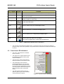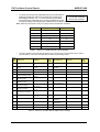
1
ZX1Se ZX2Se ZX5Se ZX10Se Document No.996-175-000-3, Revision 03 commissioning manual This manual should not be left with the end user. ZX Fire Alarm Control Panels MORLEY-IAS Table of Contents 1 INTRODUCTION ...................................................................................................1 1.1 1.2 1.3 1.4 2 USER CONTROL LEVELS ...................................................................................4 2.1 2.2 2.3 3 NOTICE ........................................................................................................................................1 WARNINGS AND CAUTIONS ............................................................................................................1 NATIONAL APPROVALS..................................................................................................................2 EN54 INFORMATION .....................................................................................................................2 LEVEL DEFINITION ........................................................................................................................4 USER PASSWORDS .......................................................................................................................4 LEVEL 3 PASSWORD .....................................................................................................................4 CONTROLS AND DISPLAYS ...............................................................................5 3.1 CONTROL KEYS ............................................................................................................................5 3.2 FRONT PANEL LED INDICATIONS ...................................................................................................6 3.3 ALPHANUMERIC DISPLAY INDICATIONS ...........................................................................................8 3.3.1 Normal Condition ................................................................................................................8 3.3.2 Display Examples – Fire Alarms.........................................................................................8 3.3.3 Display Examples – Faults..................................................................................................8 3.4 MEMORY LOCK .............................................................................................................................9 3.5 ENABLING LEVEL 2 OR LEVEL 3 ACCESS ......................................................................................10 3.5.1 Selecting the commissioning option .................................................................................10 3.6 OVERVIEW OF MENU STRUCTURE ...............................................................................................11 4 COMMISSIONING A NEW INSTALLATION.......................................................13 4.1 4.2 4.3 4.4 4.5 4.6 4.7 5 STEP 1 – GENERAL SETUP..........................................................................................................13 STEP 2 – CONFIGURE EACH SIGNALLING LOOP ............................................................................13 STEP 3 – CONFIGURE PERIPHERALS (IF REQUIRED)......................................................................13 STEP 4 – CONFIGURE OUTPUTS (SOUNDERS AND RELAYS) ...........................................................13 STEP 5 – CONFIGURE DAY MODE OPERATION (IF REQUIRED) .......................................................14 STEP 6 – CONFIGURE NETWORK OPTIONS (IF REQUIRED) ............................................................14 STEP 7 – COMMENCE NORMAL OPERATION .................................................................................14 CONFIGURE OPTION ........................................................................................15 5.1 ACCESSING THE CONFIGURE OPTION ..........................................................................................15 5.2 SIGNALLING LOOPS ....................................................................................................................15 5.2.1 Auto Learn ........................................................................................................................16 5.2.1.1 5.2.1.2 5.2.2 5.2.3 5.2.4 Full Auto Learn............................................................................................................................ 16 Quick Status Check .................................................................................................................... 16 Calibrate............................................................................................................................17 Zones ................................................................................................................................17 Devices .............................................................................................................................18 5.2.4.1 Changing Device Information...................................................................................................... 20 5.2.4.2 Location Text .............................................................................................................................. 21 5.2.4.3 Device Events ............................................................................................................................. 22 5.2.4.4 Alarm Thresholds (Device Sensitivity) ........................................................................................ 23 5.2.4.5 Restoring Sensitivity Defaults ..................................................................................................... 24 5.2.4.6 Device Actions ............................................................................................................................ 24 5.2.4.7 Class Change ............................................................................................................................. 25 5.2.4.8 Groups / Group Disablements ....................................................................................................26 5.2.4.8.1 Group Assignment................................................................................................................. 26 5.2.4.8.2 Group Disablement Input....................................................................................................... 26 5.2.4.8.3 Operation............................................................................................................................... 26 5.2.4.9 Apollo Ancillary Sounder Outputs ...............................................................................................26 5.2.4.10 Ancillary LED (Morley-IAS & System Sensor)............................................................................. 27 5.3 PERIPHERALS .............................................................................................................................28 5.3.1 Auto Learn ........................................................................................................................28 5.3.2 Calibrate............................................................................................................................29 5.3.3 Zones ................................................................................................................................29 Commissioning Manual Document No. 996-175-000-3, Revision 3 Page i MORLEY-IAS 5.3.4 5.3.4.1 5.3.4.2 5.3.5 5.3.5.1 5.3.5.2 ZX Fire Alarm Control Panels Devices............................................................................................................................. 29 Changing Device Information ..................................................................................................... 29 8-Way Input Units....................................................................................................................... 30 Remote Control ................................................................................................................ 30 Panel Status Outputs ................................................................................................................. 30 Simulating Control Keys ............................................................................................................. 30 5.4 SOUNDERS ................................................................................................................................ 31 5.4.1 Sounder Output Types ..................................................................................................... 31 5.4.2 Allocating Sounders ......................................................................................................... 31 5.4.2.1 5.4.2.2 5.4.2.3 5.4.2.4 5.4.2.5 5.4.2.6 5.4.2.7 5.4.2.8 Pattern ON ................................................................................................................................. 32 Pattern OFF................................................................................................................................ 32 Pattern DELAY ........................................................................................................................... 32 Pattern PULSE ........................................................................................................................... 33 Pattern DOUBLE KNOCK .......................................................................................................... 34 Pattern OFF-PULSE-ON ............................................................................................................ 34 Pattern OFF-ON-ON .................................................................................................................. 35 Pattern PULSE-ON-ON.............................................................................................................. 35 5.4.3 Detector Loop Addressable Sounder Circuit Controller Units (SCC)............................... 35 5.4.4 Peripheral Loop Addressable Sounder Circuit Controller Units ....................................... 36 5.4.5 Overriding Delays at Level 1 ............................................................................................ 36 5.4.6 Sounder Fault Monitoring ................................................................................................. 37 5.5 RELAYS ..................................................................................................................................... 38 5.5.1 Fault Relay ....................................................................................................................... 38 5.6 CONTROL KEYS DISABLE OPTION ............................................................................................... 38 5.7 PC (REMOTE PROGRAMMING) .................................................................................................... 38 6 INSPECT OPTION .............................................................................................. 38 7 TIME / DATE OPTION ........................................................................................ 39 7.1 7.2 7.3 8 PROGRAM INTEGRITY OPTION....................................................................... 41 8.1 9 TIME / DATE ............................................................................................................................... 39 SYSTEM (CLEAR MEMORY)......................................................................................................... 39 CRYSTAL ................................................................................................................................... 40 PROGRAM A PANEL FROM A PC USING THE ‘FIRE’ PROGRAM ...................................................... 41 POWER SUPPLIES OPTION ............................................................................. 42 10 PASSWORDS OPTION ...................................................................................... 42 11 DAY MODE OPTION .......................................................................................... 44 11.1 DAY MODES .............................................................................................................................. 44 11.2 DELAYED MODE ......................................................................................................................... 45 11.2.1 Commissioning Delayed Mode......................................................................................... 45 11.3 SENSITIVITY MODE ..................................................................................................................... 47 11.3.1 Commissioning Sensitivity Mode...................................................................................... 47 11.4 VERIFICATION MODE .................................................................................................................. 48 11.4.1 Commissioning Verification Mode .................................................................................... 48 12 SETUP OPTION.................................................................................................. 50 12.1 EVENT LOG ............................................................................................................................... 51 13 NETWORKS OPTION......................................................................................... 53 13.1 PANEL NETWORKS ..................................................................................................................... 53 13.1.1 Network - Panel Network Address ................................................................................... 53 13.1.2 Standard Network Settings for Shared Zones.................................................................. 53 13.2 PORT B PROTOCOLS .................................................................................................................. 54 Page ii Document No. 996-175-000-3, Revision 3 Commissioning Manual ZX Fire Alarm Control Panels MORLEY-IAS 14 SYSTEM EVENTS OPTION ................................................................................56 14.1 EVENT MODES ...........................................................................................................................56 14.1.1 General Events .................................................................................................................57 14.1.2 Event Logic .......................................................................................................................57 14.1.3 Define Event Outputs........................................................................................................58 15 NORMAL OPERATION.......................................................................................58 16 SUPPLEMENTARY INFORMATION ..................................................................59 16.1 LOCATING EARTH FAULTS ...........................................................................................................59 16.2 OVERRIDING DELAYS ON INDIVIDUAL OUTPUTS ............................................................................60 16.3 OPTIONAL FEATURES (OPERATIONAL FEATURES WITH REQUIREMENTS).......................................60 16.3.1 Output to fire alarm devices:.............................................................................................60 16.3.2 Delays to Outputs: ............................................................................................................60 16.3.3 Double Knock (Dependency) ............................................................................................60 16.3.4 Fault Signals from points: .................................................................................................60 16.3.5 Disablement of addressable points:..................................................................................61 16.3.6 Test Condition:..................................................................................................................61 16.3.7 Network Disablement / Enablement .................................................................................61 16.4 PRINTER SET-UP OPTIONS .........................................................................................................61 16.5 HOCHIKI MULTI-SENSOR SUPPORT..............................................................................................62 16.6 SYSTEM SENSOR/ MORLEY-IAS MULTI-SENSOR & LASER SUPPORT.............................................62 16.6.1 System Sensor/ M-IAS Multi & Laser Diagnostics............................................................62 16.6.2 System Sensor/ M-IAS Multi-sensor & Laser detectors ...................................................63 Appendix A - Day Mode Outputs ..........................................................................A-1 Table of Figures Figure 1 – ZX1Se /ZX2Se Controls and Displays ................................................................................... 5 Figure 2 – ZX5Se & ZX10Se Controls and Displays............................................................................... 5 Figure 3 – System Control LED Display .................................................................................................. 6 Figure 4 – Memory Lock Switch Location ............................................................................................... 9 Table of Tables Table 1 – Control Key Functions ............................................................................................................. 5 Table 2 – Alphanumeric and Interactive Control Keys ............................................................................ 6 Table 3 – LED Functions ......................................................................................................................... 7 Table 4 – Menu Function Overview....................................................................................................... 12 Table 5 – Discovery Sounder Beacon Volume Settings........................................................................ 19 Table 6 – Discovery Sounder Beacon Mode (Tone) Settings ............................................................... 19 Table 7 – Alarm Threshold Setting ........................................................................................................ 23 Table 8 – List of Device Actions ............................................................................................................ 25 Table 9 - Peripheral Relay Unit, remote control operation .................................................................... 30 Table 10 - Peripheral 8-way Input card, remote control operation ........................................................ 31 Table 11 - PC Programming tool - software compatibility ..................................................................... 41 Commissioning Manual Document No. 996-175-000-3, Revision 3 Page iii MORLEY-IAS ZX Fire Alarm Control Panels This page intentionally blank Page iv Document No. 996-175-000-3, Revision 3 Commissioning Manual ZX Fire Alarm Control Panels MORLEY-IAS 1 Introduction 1.1 Notice The material and instructions covered in this manual have been carefully checked for accuracy and are presumed to be correct. However, the manufacturer assumes no responsibility for inaccuracies and reserves the right to modify and revise this document without notice. These instructions cover the programming of the Fire Alarm Control Panel. Refer to the Installation Manual (P/N 996-174-000-X) for details of how to install the system and refer to the User Manual (P/N 996-182-000-X) for information on operation and use of the panel. For use with software version 837 onwards If System Sensor / Morley-IAS / Honeywell Multi-sensor or Laser devices are incorporated into your installation, ensure that you have the current Universal Loop Driver card appropriate to the protocol you are using. If you have any doubt as to the correct version to fit, please contact Technical Support. The ZX1Se, ZX2Se, ZX5Se and ZX10Se Fire Alarm Control Panels are 1, 1-2, 1-5 and 1-10 loop panels for use with analogue addressable devices from the following detector manufacturers’ ranges: Apollo S90 Hochiki Morley-IAS Nittan System Sensor 1.2 Warnings and Cautions These instructions contain procedures to follow in order to avoid injury and damage to equipment. It is assumed that the user of this manual has been suitably trained and is familiar with the relevant regulations. All equipment is to be operated in accordance with the appropriate standards applicable Commissioning Manual Document No. 996-175-000-3, Revision 3 Page 1 MORLEY-IAS 1.3 ZX Fire Alarm Control Panels National Approvals This equipment must be installed and operated in accordance with these instructions and the appropriate national, regional and local regulations specific to the country and location of the installation. Consult with the appropriate Authority Having Jurisdiction (AHJ) for confirmation of the requirements. 1.4 EN54 Information EN54-2 13.7 EN54 ! Maximum of 512 sensors / manual call points per panel. EN54 The ZX1Se, ZX2Se, ZX5Se and ZX10Se range of panels has many features, which if used inappropriately, may contravene the requirements of EN54. Where such a possibility may arise, a suitable warning is given with brief details of the EN54 requirement and the relevant section it pertains to. A typical EN54 non-compliance warning is illustrated. This Fire Control Panel complies with the requirements of EN54-2/4. In addition to the basic requirements of EN54, the panel conforms to the following optional functions. Option EN54-2 Clause Indications: Fault signals from points 8.3 Controls: Delays to outputs 7.11.1 Manual or automatic switching of delays to outputs 7.11.2 Dependency on more than one alarm signal: Type C 7.12.3 Disablement of each address point 9.5 Test condition 10 Outputs: Outputs to fire alarm device(s) EN54 The power supplies for the ZX1Se, ZX2Se, ZX5Se and ZX10Se range of panels complies with the following clauses of EN54-4. Power Supply Functions Page 2 7.8 EN54-4 Clause Derive power supply from main power source 5.1 Derive power supply from a standby battery source 5.2 Charge and monitor the standby battery source 5.3 Detect & signal power supply faults 5.4 Document No. 996-175-000-3, Revision 3 Commissioning Manual ZX Fire Alarm Control Panels EN54 N/A MORLEY-IAS In addition to the functions required by EN54-2, the panel supports a number of ancillary functions that are not required by EN54. These are outlined below: Ancillary Function Manual Section Day Mode Options: Sensitivity Mode & Verification Mode 4.5, 11.3 & 11.4 Network Options: 4.6 & 13 Configure Peripherals 4.3 & 5.3 Device Events 5.2.4.3 & 14 Alarm Thresholds (Device Sensitivity) 5.2.4.4 Device actions 5.2.4.6 Groups & Group Disablement 5.2.4.8 Sounder Output Patterns 5.4.1 PC Remote Programming 5.7 Setup Options 12 Event Log 12.1 Printer Setup Options 16.4 Class Change Input 5.2.4.7 Group Disable Input 5.2.4.8 Ancillary Sounder Outputs (Panel software 826 & later) 5.2.4.9 Commissioning Manual Document No. 996-175-000-3, Revision 3 Page 3 MORLEY-IAS ZX Fire Alarm Control Panels 2 User Control Levels 2.1 2.2 Level Definition The ZX1Se, ZX2Se, ZX5Se and ZX10Se Fire Alarm Control Panels have three user control levels. At all three levels, the LED Displays indicate the condition of the installation, the Zone LED Displays indicate the location of any fire alarm or fault and the alphanumeric display gives more detailed fire alarm or fault information. At USER LEVEL 1, all the displays are functional but the front panel control keys are inhibited. At USER LEVEL 2, all front panel controls are functional and some system operation parameters and functions can be changed. User Level 2 is reached by entering a password from level 1. At USER LEVEL 3, all front panel controls are functional and full system configuration and programming is possible. User Level 3 is reached by entering a password from either Level 1 or Level 2. User Level 3 is intended for use by the system installer / maintenance contractor. User Passwords Up to ten USER LEVEL 2 passwords can be programmed into the panel. The USER LEVEL 2 passwords can be assigned / changed at Level 3 by the installer / maintenance contractor. Level 2 passwords do not allow access to Level 3 functions. The default Level 2 Password is 1234. This should be changed. Caution: When changing the password DO NOT use ‘0’ as the first digit. 2.3 Level 3 Password The Level 3 Password is 9898. Page 4 Document No. 996-175-000-3, Revision 3 Commissioning Manual ZX Fire Alarm Control Panels MORLEY-IAS 3 Controls and Displays 3.1 Control keys The control panel has two groups of control keys. A bank of five keys contains the four system control keys: Sound Alarms, Silence / Resound, Mute, Accept and System Reset. A bank of 17 keys contains interactive and alphanumeric keys. Alphanumeric Display 0 1 2 A N B O C 3 4 5 D Q E R F 6 7 8 G T H U I P Control Keys S > < 2 3 4 5 6 7 J W K X L 8 9 10 1 2 N B O C 3 4 5 D Q E R F 6 7 8 G 9 T H U I > < J W K X L M P S V Y Z 11 Z Program / Interactive Keys Y Zone LED Display 1 0 A V 9 M System Status LED Display 12 13 14 15 16 17 18 19 2 3 4 5 6 7 8 9 10 11 12 13 14 15 16 17 18 19 20 21 22 23 24 25 26 27 28 29 30 31 32 33 34 35 36 37 38 39 40 41 42 43 44 45 46 47 48 49 50 51 52 53 54 55 56 57 58 59 60 61 62 63 64 65 66 67 68 69 70 71 72 73 74 75 76 77 78 79 80 20 Optional Zone LED Display Figure 1 – ZX1Se /ZX2Se Controls and Displays Key Legend Symbol 1 Figure 2 – ZX5Se & ZX10Se Controls and Displays Function Sound Alarms Press to Turn on ALL Sounder Outputs (i.e. evacuate building manually). NB: This will only function where EVAC (Evacuate Enable) is Enabled in the Setup menu. The default state of EVAC is Evacuate Enabled. If it has been disabled in a prior commissioning, pressing this key will have no effect. Silence / Resound Press to Turn off all activated sounders. Mute Buzzer Press to silence the internal buzzer. Accept Press to accept a Stage 1 Investigation Delay Alarm System Reset Press to cancel all alarm conditions and reset the panel. Press again to re-activate the sounders. Table 1 – Control Key Functions The alphanumeric keys normally function as a numeric keypad. During programming, these keys can be toggled to Letter Keys by pressing the CHANGE key. This gives access to letters A-M. For access to letters N-Z, press and hold the SHIFT key while pressing the appropriate letter key. Commissioning Manual Document No. 996-175-000-3, Revision 3 Page 5 MORLEY-IAS ZX Fire Alarm Control Panels Key Legend Symbol Function 0 to 9 Press to enter numbers 0-9 or letters A-J (N-W with Shift) > Press to scroll through fire alarms or faults manually on the display or letter K (X with Shift) < Press to scroll back through fire alarms or faults manually on the display or letter Z (Y with Shift) Change Press to change a display option (where allowed) or letter M (Z with Shift) M Z Enter Press to confirm entry of a multiple digit number No Press to answer No, or terminate a display option Yes Press to answer Yes, or step through a display option Shift Press to show user options on the display Press, during programming, to allow entry of Letters N-Z Table 2 – Alphanumeric and Interactive Control Keys 3.2 The control keys are disabled at USER LEVEL 1. Pressing the SHIFT key will cause the display to prompt for entry of the Level 2 password. The password must be entered to re-enable the control keys at Level 2. Front Panel LED Indications The Level 1 LED Indicators are divided into two sections. The upper array of LED Indicators shows the operational conditional of the panel and the installation. FIRE FAULT Acknowledged Disablement Test The lower array of Zone LED indicators shows the location of a fire alarm or fault. The standard Zone LED Indicators provide identification for up to 20 zones. On the ZX5Se and ZX10Se panels, this can be extended by adding either a further 20 zones (to give a total of 40 zones) or a further 60 zones (to give a total of 80 zones). Sounder Fault Delayed Mode Relays Disabled Earth Fault System / CPU Fault Sounders Disabled Alarms Silenced Supply Fault The LED Indicators illuminate as red, yellow or green to give a clear indication of the panel status as follows: Power Figure 3 – System Control LED Display Page 6 Document No. 996-175-000-3, Revision 3 Commissioning Manual ZX Fire Alarm Control Panels Indicator Colour MORLEY-IAS Function How to Clear FIRE Red The panel has detected a fire alarm condition, or the ‘Sound Alarms’ key has been pressed. Identify and correct the condition causing the alarm and then perform a panel reset. Fault Yellow The panel has detected a fault. Correct the condition causing the fault and then perform a panel reset. Acknowledged Yellow A fault or alarm has been acknowledged and the internal buzzer silenced. Correct the condition causing alarm or fault and then perform a manual reset. NOTE: If another alarm or fault occurs, the internal buzzer automatically resounds. Disablement Yellow Part of the system, either input or output, has been disabled manually by the user. Re-enable the device or devices. Refer to Disablement Function. Test Yellow The system is in test mode. Zone LED indicators show which zones are being tested. Cancel test when finished. Sounder Fault Yellow This indicates a wiring fault with one of the sounder output circuits. Correct the fault condition and then perform a panel reset. Delayed Mode Yellow This indicates that the system is operating with delays to the sounder outputs and the delays are active (in force). The delays may be enabled or disabled. Refer to Disablement Function. Relays Disabled Yellow The relay outputs have been disabled. Refer to Disablement Function. Earth Fault Yellow An earth connection fault has occurred on a cable. Correct the fault condition and then perform a panel reset. System / CPU Fault Yellow The CPU has reset or a system fault has occurred. Correct the problem, if appropriate, and then perform a panel reset. Sounders Disabled Yellow Some or all of the sounder outputs have been disabled. Alarms Silenced Yellow The sounder outputs have been silenced. Correct the alarm condition and then perform a panel reset. NOTE: Press SILENCE / RESOUND again to reactivate the sounders. If a new alarm occurs, the alarms will resound. Supply Fault Yellow There is a problem with the power supply, battery or supply input. Correct the fault condition and then perform a panel reset. Power Green STEADY: Indicates AC Power is present. FLASHING: Indicates a loss of AC Power. See Supply Fault. Zone FIRE Red FLASHING: The zone is in a fire alarm condition. Correct the alarm condition and then perform a panel reset. Zone Fault Yellow FLASHING: The zone contains faulty devices. Correct the fault condition and then perform a panel reset. STEADY: The zone is either disabled or in test mode. Re-enable devices or cancel test mode. 1 1 Refer to Disablement Function. Table 3 – LED Functions 1 This includes loop-based sounders. Commissioning Manual Document No. 996-175-000-3, Revision 3 Page 7 MORLEY-IAS 3.3 ZX Fire Alarm Control Panels Alphanumeric Display Indications The alphanumeric liquid crystal display gives 160 characters of information on a 4-line display. The display is illuminated to assist viewing under dim ambient light conditions. NOTE: Should the AC Mains fail; the back lighting on the liquid crystal display will be turned off to conserve battery power. When the numeric keypad is not in use, the display will revert to automatically scrolling through any fire alarm or fault conditions present on the panel. If there are no alarm or fault conditions, the display will show the date and time. Pressing the SHIFT key will show a list of optional functions or prompt for the level 2 password. 3.3.1 Normal Condition 3.3.2 Display Examples – Fire Alarms 3.3.3 Display Examples – Faults Page 8 Document No. 996-175-000-3, Revision 3 Commissioning Manual ZX Fire Alarm Control Panels 3.4 MORLEY-IAS Memory Lock To make changes that affect the configuration of the system, such as adding detectors, the system memory must first be unlocked. I SO LA TE EL SE WHE RE FS 1: T5 A 98 - 264 VA C A ZX2Se Only Open the enclosure door and move the memory lock switch to the open position. The Memory Lock Switch is located on the CPU Board. The figure opposite shows the interior of the ZX1Se and ZX2Se Fire Alarm Control Panels. The ZX5Se and ZX10Se Fire Alarm Control Panels use the same CPU Board and have a similar arrangement. AUX O/P SOUNDER OUTPUTS REL AY 1 REL AY 2 CPU Board Port A: Programming Printer Port/ Printer Header Memory Lock Figure 4 – Memory Lock Switch Location Ensure that the Memory Lock Switch is in the open position prior to performing any programming. Ensure that the Memory Lock Switch is in the lock position before returning the panel to normal operation (wait for prompt on display). Commissioning Manual Document No. 996-175-000-3, Revision 3 Page 9 MORLEY-IAS 3.5 ZX Fire Alarm Control Panels Enabling Level 2 or Level 3 Access To enable Level 2 or Level 3 operation, press the SHIFT key. The display will then show: Press the ‘Yes’ key and the display will prompt for entry of the password. Enter the 4-digit, Level 2 password. The display then shows the Main Menu of user options. If a key has not been pressed for a certain period, the display will revert to the normal Level 1 display showing the system status message. To re-show the menu display, press the ’SHIFT’ key. If a key has not been pressed for a specified period of time, (normally 5-minutes – programmable), then ‘Level 2’ access will be automatically cancelled. It will be necessary to re-enter the password to re-activate Level 2 functions. Note: As a commissioning aid the level 2 automatic timeout can be disabled at access level 3 (refer to Section10 Passwords Option). Leaving the panel in this state is not recommended and must only be done with the written agreement of the local fire officer. For detailed information on the Level 2 user options, refer to the User Manual (P/N 996-182-000-X). 3.5.1 Selecting the commissioning option To access the commissioning functions in the panel, press ‘1’ to select the commission option. The display will prompt for entry of the Level 3 password. Enter the Level 3 password using the numeric keys. The display will then show the commissioning menu options. Page 10 Document No. 996-175-000-3, Revision 3 Commissioning Manual ZX Fire Alarm Control Panels 3.6 MORLEY-IAS Overview of Menu Structure The commissioning menu options are presented in three different screens (Pages). When the commissioning menu option is selected, the display will show: PAGE 1 To move between the three commissioning screens, press the ‘Yes’ key. PAGE 2 PAGE 3 Page 1 Option Configure Function To configure the connection and operation of the signalling loop devices, peripheral devices, sounder circuits and relay outputs. Also provides configuration for upload / download of configuration data from a PC. 2 Inspect Provides the same functionality as the configure option but with view only. This allows the data to be inspected without risking any inadvertent changes. Normal Operation To return the panel to normal operation – Level 2. Time / Date To allow the date and time and other clock functions to be changed. Also allows the system memory to be cleared to return the panel back to factory default settings. Program Integrity To show the version of the software installed in the panel. To show the status of the operating program and configuration memory. Power Supplies Shows the current state of the AC Mains and Battery supply conditions. Passwords To define the number of User Level 2 passwords. To define the value of each Level 2 password. To define the maximum time the panel will remain at Level 2, without any key pressed, before inhibiting the keys and returning to Level 1 operation. Commissioning Manual Document No. 996-175-000-3, Revision 3 Page 11 MORLEY-IAS 3 Day Modes ZX Fire Alarm Control Panels To define which, if any, of the following day modes are in operation. Delayed Mode Sensitivity Mode Verification Mode To define the effective times of operation, (i.e. start and finish). Setup Options To define system setup parameters. Network To define and configure the operation of the panel in a networked system. Events To define system events that provide a more flexible cause and event function than that available from standard zone-based,0 ringing options. Table 4 – Menu Function Overview Page 12 Document No. 996-175-000-3, Revision 3 Commissioning Manual ZX Fire Alarm Control Panels MORLEY-IAS 4 Commissioning a New Installation 4.1 4.2 This section provides a guide to the steps that are required to commission a new installation. Precise details on how to perform each step, and on the functionality of each programming option, are given in appropriate sections of this manual. Step 1 – General Setup Ensure that the panel configuration memory is cleared and returned to factory settings. Refer to Time / Date – System on Page 2 of the Commissioning Menus. Select the ‘Setup options’ from Page 3 of the Commissioning Menus. Press ‘Yes’ to step through each item to inspect the factory default settings and to make changes as required. For example, to enter service telephone number and company name. Step 2 – Configure Each Signalling Loop Select the CONFIGURE option from Page 1 of the Commission Menus and then perform the following. 1. Select ‘Signalling Loop 1’. 2. Perform an ‘Auto Learn’ 3. Select ‘Devices’ and change sensor location text as required. 4. Assign Zones. Repeat actions 1-4 above for each signalling loop connected to the panel. Enter Zone descriptions. NOTE: 4.3 4.4 1. If using a PC to program the panel, actions 3 and 4 above will already have been defined on the PC. 2. When using ZX panel software version 826, or later, and the Apollo protocol with ancillary sounders fitted, refer to Section 5.2.4.9. 3. When using ZX panel software version 834, or later, and Morley-IAS or System Sensor protocol with ancillary LEDs fitted, refer to Section 5.2.4.10. For use with software version 826 onwards For use with software version 834 onwards Step 3 – Configure Peripherals (if required) Select the CONFIGURE option from page 1 of the Commission Menus and then perform the following. 1. Select ‘Peripheral’. 2. Perform an ‘Auto Learn’. 3. Select ‘Devices’ and change each unit’s location text as required. 4. Assign Zones and set the operation of the unit. Step 4 – Configure Outputs (sounders and relays) Select the CONFIGURE option from page 1 of the Commission Menus and then perform the following. 1. Select ‘Sounders’, if zoned ringing patterns are required and program accordingly. 2. Select ‘Relays’, if zoned operation is required and program accordingly. Commissioning Manual Document No. 996-175-000-3, Revision 3 Page 13 MORLEY-IAS 4.5 Finally, select the INSPECT option from page 1 of the Commission Menus. Compare the commissioning data entered against the installation sheets. This facility allows the data to be inspected without risking any inadvertent changes. Step 5 – Configure Day Mode Operation (If required) EN 54-2 7.11 EN54 ! Select the DAY MODES option from Page 3 of the Commission Menus and then perform the following. 1. Select ‘Delayed Mode’, if the sounders and outputs are to be delayed. (NOTE: Must be enabled at Level 2 to activate). 2. Select ‘Sensitivity Mode’, if the detectors are to have different pre-alarm and fire alarm settings during day / night. 3. Select ‘Verification Mode’, if the analogue signals are to be verified before the panel registers a fire alarm. Program the required mode as required. Refer to Appendix A Day Mode Options for details of the alternative strategies that may be configured for delays to outputs. Step 6 – Configure Network Options (If required) 4.7 Delays to Outputs Delayed mode complies with the requirements of EN54-2 7.11 4.6 ZX Fire Alarm Control Panels Select the ‘NETWORK’ option from page 3 of the Commission Menus. Press ‘Yes’ to step through each item to inspect the factory default settings and change as required. For example, panel address, number of slave panels, etc. Step 7 – Commence Normal Operation Before finally commencing normal operation, perform the following. 1. Select ‘PASSWORDS’ from page 2 of the Commission Menus. Set the number of Level 2 passwords and define the value of each password. 2. Select ‘PROGRAM INTEGRITY’ from page 2 of the Commission Menus. Check and record the program checksums. Select ‘NORMAL OPERATION’ from page 1 of the Commission Menus. Remember to lock the memory!!! Page 14 Document No. 996-175-000-3, Revision 3 Commissioning Manual ZX Fire Alarm Control Panels MORLEY-IAS 5 Configure Option 5.1 Accessing the Configure Option Page 1 of the Commission menu is shown below: The CONFIGURE option allows the Signalling Loops, peripherals, sounders and relays to be programmed. It also enables the function to allow the panel to be programmed by a PC. Press ‘1’ to select the ‘CONFIGURE’ option. The CONFIGURE option and all sub menu options require the Memory Lock to be open. The display then shows a menu of options as follows: NOTE: The menu will only show the number of signalling loops programmed during setup (Refer to the Setup Option). The ZX2Se can only have two loops maximum. 5.2 Signalling Loops After selecting a loop from the configure menu, the display will present a list of options as follows: The words ‘CONFIGURE: Loop 1’ on the top line of the menus provides a reminder that panel is in configuration mode, with loop 1 selected. Select the required option by pressing the appropriate numeric key. When commissioning a new panel, start by performing an ‘Auto Learn’. This will cause the panel to search for all devices installed on the loop. Commissioning Manual Document No. 996-175-000-3, Revision 3 Page 15 MORLEY-IAS ZX Fire Alarm Control Panels 5.2.1 Auto Learn This facility saves considerable time and effort when installing a system, or when changing sensor configuration. It allows the system to learn for itself what devices have been installed on a particular loop. Press ‘3’ from the CONFIGURE menu to select ‘Auto Learn’. The display will respond with the message: 5.2.1.1 Full Auto Learn To proceed with ‘Auto Learn’, press the ‘Yes’ key. The system will confirm your command with the message ‘Program running’ on the display. It may take several minutes to learn a complete loop. Each possible sensor address is checked to see if any detector is installed at that address. If a detector has been installed, the panel determines the type of the detector. If more than one detector is located at a single address, or the detector type code is invalid, a warning message will appear on the display. Do not press any key until the display changes from the ‘program running’ message. Once the system has finished learning, it will respond with a display giving a summary of the detectors found on the loop. For example. This display should be checked, against the installation sheets, to ensure that the system has found the correct number of devices. Pressing any key then restores the display to the normal commissioning menu. The Auto Learn sequence should be repeated for each loop on the system. It can be used as many times as required and does not affect the text description used to describe the location of each sensor. Always verify that the system has found all devices correctly. Use the ‘Devices’ option to obtain detailed information on the device type and to see the address of each device found on the loop. 5.2.1.2 Quick Status Check To perform a ‘Quick Status Check’, press the ‘No’ key instead when prompted to perform the Auto Learn. The system will respond immediately with a display giving a summary of the detectors already programmed for this loop. For example. Page 16 Document No. 996-175-000-3, Revision 3 Commissioning Manual ZX Fire Alarm Control Panels MORLEY-IAS This function is useful to establish what the panel thinks should be physically connected to the loop prior to performing a full Auto Learn. 5.2.2 Calibrate The panel does not perform any automatic drift compensation on the analogue values returned from the detectors. However, the panel may be commanded to perform a calibration / contamination check either manually or automatically (refer to Section 12). Always ensure that: 1. The detectors are clear of smoke. 2. Re-calibrate when replacing detectors. The devices connected to the loop can be manually calibrated. Press ‘4’ from the configure menu to select ‘Calibrate’ option. The display will confirm that the calibration function is in operation and will return to the normal commissioning menu on completion. For further information, refer to the documentation supplied with the loop driver. 5.2.3 Zones The system can be divided into 20, 40 or 80 ‘zones’ for the ZX5Se and ZX10Se panels & 20 ‘zones’ for the ZX1Se and ZX2Se panels. Each zone may contain one or more devices. The zone assignment option allows the commissioning engineer to quickly assign the sensors to the appropriate zone. The default allocates all devices to zone 1. Press ‘1’ from the configure menu to select the ‘zones’ option. The display will then show: This display shows several pieces of information. To avoid ambiguity as to what can be changed the left-hand numeric value of the editable item will flash. If you want to change it then simply type the new value over the top. For example: The ‘from’ address number (i.e. 001) will be flashing to show this item can be changed, if required. To make this address 24, enter ‘024’. The display will then show the new zone range as: The ‘>’ and ‘<’ keys can be used to move across the display. For example, if the ‘200’ in the ‘to’ address field is flashing, then the ‘zone’ field can be modified by pressing the ‘>’ key to make the zone number flash and then entering the desired value. The backspace ‘<’ key also moves back one digit - useful for correcting errors when entering numbers. The configuration shown on the display becomes effective immediately after the ‘Enter’ or ‘Yes’ key is pressed. Pressing the ‘No’ key will abort the operation and return to the commissioning menu. If the ‘to’ address value is less than 200, the ‘Yes’ or ‘Enter’ key automatically advances to the next zone to be defined. When all of the devices for the loop being configured are assigned to zones, then the program will advance to the zone description - text entry menu. Commissioning Manual Document No. 996-175-000-3, Revision 3 Page 17 MORLEY-IAS ZX Fire Alarm Control Panels Each zone can have a description assigned to it to identify the area covered by the zone. This description will appear on the liquid crystal display if any sensor in the zone detects a fault or fire. The description can be amended by highlighting the location text (using the ‘>‘ and ‘<‘ keys), pressing ‘Change’ and entering either, letters, numbers or keywords. This procedure is identical to that used for editing the sensor location text described in Section 5.2.4.2 below. 5.2.4 Devices The ‘Devices’ option from the display gives information on the various types of device fitted on a loop. Press 2 to select the ‘Devices’ option. The system will ask which address you want to start at: If you would like to start at a different address, then press the ‘Change’ key and enter your required address, otherwise say ‘Yes’ to continue. The display then gives detailed information about the Device at the chosen address. Loop Zone Address Location Text Event Device Typ Analogue Signal Digital input status (Apollo only) H=Logic High L=Logic Low For Apollo protocol loops with Ancillary Sounders attached to applicable sensors, the display then gives detailed information about the device at the chosen address with an indicator ‘+’ at the end of the text description of the device (to which For use with software the ancillary sounder is attached). Applicable sensors to which Apollo version 826 onwards. ancillary sounders can be connected include ionisation, temperature detectors, etc. For Morley-IAS and System Sensor protocol loops with ancillary LEDs attached to applicable modules: the display gives information about the device at the chosen address with an indicator ‘+’ at the end of the text description of the device (to which the ancillary LED is attached). These ancillary LEDs are, in fact, configured as if they were relays, meaning that they perform in the same way a relay does. These outputs, therefore, cannot be pulsed. The ZX For use with software Series of fire control panels can turn on four device LEDs in alarm. The version 834 onwards panel can turn on additional ancillary LEDs, up to the maximum current supported by the loop. Page 18 Document No. 996-175-000-3, Revision 3 Commissioning Manual ZX Fire Alarm Control Panels MORLEY-IAS For Apollo protocol loops with addressable Discovery Sounder Beacon (DSB) types 58000-005, 58000-007 and 45681-393, the digital input For use with software status displays ‘DISCOV 2-0 = LLL’ and the devices may be edited, version 845 onwards. through the device configuration menu, to allow the default volume and mode (tone) settings to be changed (refer to tables below for available volume and mode settings). Note: Selecting volume level 1 does not comply with the requirements of EN54-3. Volume Level dB(A) (58000-005/007) dB(A) (45681-393) 1 60 60 2 69 70 3 75 74 4 81 78 5 87 82 6 93 86 7 100 90 Table 5 – Discovery Sounder Beacon Volume Settings Mode /Byte Value The alarm (primary tone) and alert (secondary tone) tone pair may be configured from the options given in Table 6 – Discovery Sounder Beacon Mode (Tone) Settings below. Primary Tone Frequency 1 Apollo – Evacuation Tone 2 Alternating – (Hochiki & Fulleon) 3 Medium Sweep 800Hz to 970Hz at 1Hz 4 Fast Sweep 2500Hz – 280Hz at 9Hz Dutch Slow Whoop (sweep) 500Hz – 1200Hzfor 3.5s, 0.5s off 5 6 7 8 9 10 11 12 13 Tone Number Secondary Tone Frequency 550Hz for 0.5s, 825Hz for 0.5s T1 Apollo Alert Tone 1s off, 825Hz for 1s T0 925Hz for 0.25s, 626Hz for 0.25s T12 Continuous – (Hochiki & Fulleon) 925Hz T11 T14 Continuous 970Hz T13 T16 Continuous 2850Hz T15 T3 Continuous 825Hz T2 1200Hz – 500Hz for 1s T4 Continuous 825Hz T2 Swedish Fire Tone 660Hz, 150ms on, 150ms off T18 Swedish all clear signal - Continuous 660Hz T17 Aus (fast rise sweep) 3x (500Hz – 1200Hz for 0.5s), 0.5s off T6 Aus Alert Tone 420Hz, 0.625s,0.625s off T5 NZ (slow rise sweep) 500Hz – 1200Hz for 3.5s, 0.25s off T7 NZ Alert Tone 420Hz, 0.625s,0.625s off T5 US Temporal LF (ISO 8201) 3x (970Hz, 0.5s on, 0.5s off), 1s off T19 Continuous 970Hz T13 US Temporal HF (ISO 8201) 3x (2850Hz, 0.5s on, 0.5s off), 1s off T20 Continuous 2850Hz T15 n/a T8 Simulated Bell intermittent 1s off, 1s on T9 n/a T10 Emergency Warning Siren All Clear n/a T22 DIN Tone (sweep) Simulated Bell - Continuous Emergency Warning Siren Tone Number 14 Continuous 970Hz T13 Pulsed at 1s off, 1s on 970Hz T21 15 Apollo Evacuation Tone 550Hz for 0.5s T1 Apollo Alert Tone 1s off, 825Hz fro 1s T0 Table 6 – Discovery Sounder Beacon Mode (Tone) Settings Commissioning Manual Document No. 996-175-000-3, Revision 3 Page 19 MORLEY-IAS ZX Fire Alarm Control Panels The Loop & Battery Calculator must be used to determine the maximum number of LEDs able to be turned on in alarm. Loop Zone Address Location Text Event Device Type 5.2.4.1 Ancillary Sndr Attached Indicator Analogue Signal Digital input status (Apollo only) H=Logic High L=Logic Low Changing Device Information Changes are made by first pressing the ‘Change’ key. A menu of items that can be changed will appear according to the type of device, For example. An ionization smoke detector will allow changes on: For Apollo protocol loops with Ancillary Sounder attached (or to be attached or removed) to/from an ionization smoke detector will allow changes on: Page 1 Page 2 To add or remove an ancillary sounder to this device, select ‘7) Sndr’ and respond to the prompt given. For Apollo protocol loops with Sounder Beacon types 58000-005/007 and 45681-393 an additional menu option on page 2 is displayed to allow the sounder volume and mode settings to be edited: [ Page 20 Document No. 996-175-000-3, Revision 3 Commissioning Manual ZX Fire Alarm Control Panels MORLEY-IAS Select ‘9) Level and Mode’ to select Level (volume) and Mode (tone) option. The default settings* are displayed as below: [ * Level (volume) 3 = 75dB A. Mode (tone) 14 = Primary (Continuous 970Hz) and Secondary (Pulsed at 1s off, 1s on 970Hz). Press the ‘Change’ key to edit the Level (volume) and Mode (tone) settings and then press ‘Enter’ or ‘Yes’ to accept the changes and exit. Note: The Level and Mode setting option is only available with Apollo Discovery sounder beacons. A call-point will allow changes on: Press the appropriate number to select the required option. Press ‘No’ to return to the device information display. NOTE: This change facility is only available while in the configure mode. It cannot be invoked from the INSPECT option, thus preventing inadvertent changes to the system. 5.2.4.2 Location Text To enter or modify the location text assigned to a device, press ‘1’ to select the ‘Sensor Text’ option. The display will show the current location text and provide additional information to assist in making any changes. Three modes of text entry are available – ‘KeyWords’, ‘Numbers’ and ‘Letters’. The mode currently in use is always shown in square brackets in the top right hand corner of the display. The required mode is selected by pressing either the’ Yes’ (KeyWords) button or the ‘No’ (Letters/Numbers) button. A) Numbers The number mode allows you to add numbers 0 to 9 on the display. Advance (>) and Backspace (<) editing keys are also available in this mode. For example, to change from ‘ROOM 86’ to ‘ROOM 87’, first press the backspace key once to erase the ‘6’, then press key ‘7’. The display will immediately show the new description as below: Commissioning Manual Document No. 996-175-000-3, Revision 3 Page 21 MORLEY-IAS ZX Fire Alarm Control Panels The cursor symbol ‘_’ indicates where you are on the line. It will not appear in the description shown on the device display. B) Letters Any letter in the alphabet can be entered from the Letter Mode. Pressing the appropriately-labelled key enters letters A to M. To obtain letters N to Z, first hold down the ‘Shift’ key before pressing the required letter. If you are in letter mode and wish to remove any previously entered text or add spaces, change to number mode, use the ‘<’ key to erase the text, or the ‘>’ key to insert a space then return to letter mode. C) KeyWords This mode is selected by pressing the ‘Yes’ (KeyWords) key. The mode is again confirmed in the box at the top right of the display. KeyWords mode provides a quick means of entering frequently-used text with a single keystroke. For example, suppose the word ‘CORRIDOR’ is to replace the text ‘ROOM 87’ from the above example. Select ‘KeyWords’ mode and use the ‘<’ key to erase ‘ROOM 87’ from the display. The cursor symbol ‘_’ will then be positioned ready to enter the new text as shown below: To enter the word ‘CORRIDOR’, press the ‘3’ key: NOTE: When in ‘Keywords’ entry mode a number of different pre-programmed keywords can be displayed and selected by using the ‘Yes’ key to step through the list. NOTE: To change back to numbers or letters mode, press the ‘No’ key. 5.2.4.3 Page 22 Device Events Assigning an event number to a device causes the panel to generate the event whenever the device goes into alarm. Document No. 996-175-000-3, Revision 3 Commissioning Manual ZX Fire Alarm Control Panels MORLEY-IAS For detailed information on events, refer to Section 14. The event is latched until the panel is reset. Transient events that automatically unlatch are created for devices with actions set to ‘Non-latched’. 5.2.4.4 Alarm Thresholds (Device Sensitivity) If the panel has the day -sensitivity mode option enabled, then an individual detector (heat or smoke) can be programmed to have alternative pre-alarm and alarm values. For example, assume a temperature detector located on loop 1, address 26 requires: Time Period Pre-alarm Level Alarm Level Between 06:30 and 17:45 50 62 At all other time of the day – default settings 45 55 Table 7 – Alarm Threshold Setting This can be achieved as follows: 1. Select the required device address and then press the ‘Change’ key. 2. Press ‘4’ to select the ‘Alarm Threshold’ option. (This option is only displayed for smoke and temperature detectors). The display will then prompt the alternative thresholds to use when in day mode. 1. Press ‘No’ to reject the value shown and then enter the required numeric value. For example, enter a level of 62. 2. The display will then prompt the pre-alarm threshold level. 1. Press ‘No’ to reject the value shown and then enter the required numeric value. For example, enter a level of 50. The panel will not allow the pre-alarm threshold to be higher than the fire alarm. If the value shown is correct, press Yes to step on and leave the value unchanged. The values presented and entered depend on the make of signalling device. Refer to the instructions supplied with the loop driver card for information on allowed settings. Both thresholds have now been set and the display reverts to showing the present analogue output from the sensor. However, because alternative pre-alarm and fire alarms have been set the display will automatically show these whenever this device is called up in the inspect or configure modes. Commissioning Manual Document No. 996-175-000-3, Revision 3 Page 23 MORLEY-IAS ZX Fire Alarm Control Panels P=050 signifies the daytime pre-alarm is now at 50. F=062 signifies the daytime fire alarm is now at 62. Step through and adjust any other devices as required. These alternative thresholds are enabled as defined in the Day Mode setup configuration. The panel will not allow the threshold to be raised above the measuring range for the sensor. However, the commissioning engineer should always test the detector and prove that the system is giving proper fire protection. Apollo ‘Discovery’ detectors also support programmable sensitivity bands, defaulting to ‘band 3’. When the panel detects a Discovery device, it will precede the fire threshold level shown above with an option to also change the sensitivity band during day mode operation. If required, change the sensitivity bias towards band 1 (smoke) or band 5 (heat). 5.2.4.5 Restoring Sensitivity Defaults Each time the panel performs an ‘Auto Learn’, it will check to see if a different type of detector has been installed to the device type information stored in memory. If so, the panel will automatically reset the pre-alarm and fire alarm settings back to the standard factory defaults. To reset the sensitivity thresholds for all devices: 1. Disconnect the devices from the loop and perform an auto-learn. 2. Reconnect the devices to the loop and perform an auto-learn. NOTE: Apollo I/O Units will reset to the factory default setting of FAULT. 5.2.4.6 Device Actions The action taken by both smoke and temperature detectors is fixed to always give pre-alarms and fires. Most other devices can have their alarm action re-defined as required. This ability to change the alarm action is signified on the display by the option ‘Action’ appearing on the device menu when the change key is pressed. Press ‘6’ to select the action option and the display will show the current action assigned to the input device. For example a call-point (pull station) will normally show: EN54 ! Page 24 If the action shown is not correct for the application, press the ‘Change’ key. Each time the ‘Change’ key is pressed the action will cycle through the available options. The available actions are given in the table overleaf. Note: The selection of certain device actions must be used with extreme care. If used inappropriately, the requirements of EN54-2 may be contravened. Document No. 996-175-000-3, Revision 3 Commissioning Manual ZX Fire Alarm Control Panels 1. Fault MORLEY-IAS Closing the input produces a ‘warning’ message on the display. The common ‘Fault’ LED and the corresponding zone fault LED will also illuminate. 2. Zone Fire Closing the input forces the designated zone into fire. Any action resulting from the first zone event depends upon the programmed zone output pattern. Used for Double-knock applications. Note: With panel software prior to version 834 this was called ‘Fire’. 3. Bomb Alert Closing the input produces a ‘bomb alert’ from the designated zone. All sounders / relay outputs will operate according to their programming for this zone. 4. Class Change 1 5. Security 6. Non-latch 7. Plant 8. Group Disable 9. Confirmed Fire Closing the input forces all system sounders to operate. This condition is not latched. Once the input is removed the sounders will stop operating. Allows the input class ‘security alert’ to be configured. 1 Allows an input device to create a temporary system event that is cleared when the input is restored to its normal condition. This option is not normally used on fire systems. Contact technical support department for further information before using this option. Closing the input produces a ‘warning’ message on the LCD, but does not illuminate the yellow fault LED’s. 1 Allows an input device, remote from the panel, to disable a group of detectors. Closing this input, e.g. using an MCP, initiates a full Evacuate condition unless the Confirmed Fire input is from a zone with a programmed delay. 10. Panel Reset This will reset the panel. Performs in the same way as the panel RESET key. 11. Evacuate Will operate all configured outputs immediately. 12. Silence Alarms Will de-activate all currently active sounder outputs. 13. not used Allows an input device to be turned off. Any action or state change at the input will be ignored. Table 8 – List of Device Actions Press the Yes key once the desired option is shown. The display will then revert to the normal device display, but will in addition show in the bottom right corner the alarm action of the input. For example: 5.2.4.7 The display can also be placed in this ‘action display’ mode at any time by pressing the ‘6’ key when viewing any device. Class Change EN54-2 EN54 N/A 1 Class Change The operation of a ‘Class Change’ input MUST be restricted to LEVEL 2 ACCESS only. Install accordingly using a key switch to activate or locate in a restricted area. These are local to the panel only and are not broadcast across a network. Commissioning Manual Document No. 996-175-000-3, Revision 3 Page 25 MORLEY-IAS 5.2.4.8 Groups / Group Disablements The group assignment / group disablement function allows a range of detectors and input devices to be disabled remotely from the panel using a single input device. The initiating input device can be any loop-input circuit, call point or peripheral input circuit. EN54-2 EN54 N/A 5.2.4.8.1 5.2.4.8.2 ZX Fire Alarm Control Panels Group Disable The operation of a ‘Group Disable’ input MUST be restricted to LEVEL 2 ACCESS only. Install accordingly using a key switch to activate. Group Assignment Each detector or input device that is to be disabled must be assigned to a specific group using the Group command in the Change Device options. The input device that will initiate the group disablement must also be assigned to the same group. Press ‘8’ to select the group option. Group Disablement Input The input device to be used to control the group disablement must have its ‘Action’ set to GroupDisable. ONLY one input device must be assigned to act as the Group Disable input for a specific group. 5.2.4.8.3 Operation When the input device is activated, the detectors and input devices within the specified group will be disabled. The LCD on the panel will indicate there are ‘xxx Inputs Disabled’ where, ‘xxx’ is the number of devices. The Disablement LED will illuminate to indicate that devices are disabled. If all the devices in a zone are disabled, then the relevant zone LED will also be illuminated. The internal buzzer of the panel will not sound. When the input device is returned to normal, the group disablement will be cancelled. If the initiating input device is assigned to the same zone as the group-disable devices, then the Zone LED will not illuminate. The input device itself cannot be disabled and hence, not all devices in the zone will be disabled. To disable the initiating input device, use the Disable Device function in the panel. 5.2.4.9 Apollo Ancillary Sounder Outputs For the Apollo protocol only with software version 826 onwards: where Apollo Ancillary Sounders have been fitted to appropriate devices on the loop, ensure that you have noted the location / address of each device to which an ancillary For use with software sounder has been attached. From the Control Panel, Commissioning version 826 onwards menu: 1. Select the appropriate Apollo loop 2. Select ‘Devices’ 3. Select the address which has an ancillary sounder attached 4. Select ‘Change’ 5. Select ‘7) Sndr’ to add (or remove) an ancillary sounder Page 26 Document No. 996-175-000-3, Revision 3 Commissioning Manual ZX Fire Alarm Control Panels MORLEY-IAS Repeat the last 3 items above for each ancillary sounder fitted. Note that when you have added an ancillary sounder to a device, the Text description displayed in the ‘Devices’ menu will be modified such that a ‘+’(positive) sign will be appended to the description. This is used to indicate that the device described has an ancillary sounder attached to it. Note that to remove ancillary settings you must wipe the panel memory or download a new configuration, with the device removed, or change the EEPROMs for a different software version. Ancillary settings will persist across auto-learn operations. 5.2.4.10 Ancillary LED (Morley-IAS & System Sensor) For the System Sensor and Morley-IAS protocol only with software version 834 onwards, the MI-MM3 micro-monitor module ancillary LED can be configured to activate as a ‘relay’. Where MMI-MM3 micro-monitor devices have been fitted to appropriate devices on the loop, make sure that you have noted the location /address of each device to which an ancillary LED has been connected. From the control Panel, Commissioning menu: 1. Select the appropriate loop 2. Select ‘Devices’ menu 3. Select the address which has an ancillary LED attached 4. Select ‘Change’ 5. Select ‘7) LED’ to add (or remove) an ancillary LED. Repeat the last 3 items above for each ancillary LED fitted. Note that when you have added an ancillary LED to a device, the Text description displayed in the ‘Devices’ menu will be modified such that a ‘+’(positive) sign will be appended to the description. This is used to indicate that the device described has an ancillary LED attached to it. Note that to remove ancillary settings you must wipe the panel memory or download a new configuration, with the device removed, or change the EEPROMs for a different software version. Ancillary settings will persist across auto-learn operations. Commissioning Manual Document No. 996-175-000-3, Revision 3 Page 27 MORLEY-IAS 5.3 ZX Fire Alarm Control Panels Peripherals All panels have the facility to drive various Input and Output devices on the RS485 peripheral bus (the left-hand serial port D on all base cards). Select the configure option from page 1 of the Commission menus. Press ‘6’ to select the 'Peripherals' option. The display will present a list of options for you to choose from as follows: The top left hand corner of the display reminds you that you are in configuration mode and shows that it is the peripheral bus that is being examined. Press the appropriate number to select the required menu option. 5.3.1 Auto Learn This facility saves considerable time and effort when installing a system, or when changing the units connected to the peripheral bus. It allows the system to learn for itself what devices have been installed on the peripheral bus. Press ‘3’ from the configure menu to select ‘Auto Learn’. The display will respond with the message: To proceed with ‘Auto Learn’, press the ‘Yes’ key. The system will confirm your command with the message ‘Program running’ on the display. It may take up to half a minute to learn the peripheral loop. Each possible peripheral device address is checked to see if any device is installed at that address. If a device has been installed, the panel determines its type. If more than one device is located at a single address, or the device type code is invalid, a warning message will appear on the display. Do not press any key until the display changes from the ‘Program running’ message as the keypad will not respond to any key presses during this period. Once the system has finished learning, it will respond with a display giving a summary of the detectors found on the loop. For example. Page 28 Document No. 996-175-000-3, Revision 3 Commissioning Manual ZX Fire Alarm Control Panels MORLEY-IAS This display should be checked, against the installation sheets, to ensure that the system has found the correct number of devices. Pressing any key then restores the display to the normal commissioning menu. The Auto Learn sequence can be used as many times as required and does not affect the text description used to describe the location of each sensor. Always verify that the system has found all devices correctly. Use the ‘Devices’ option to obtain detailed information on the device type and to see the address of each device found on the loop. 5.3.2 Calibrate The calibrate function is identical to the routines described in Signalling Loops Section. Refer to Section 5.2.2. 5.3.3 Zones The Zone function is identical to the routines described in Signalling Loops Section. Refer to Section 5.2.3. 5.3.4 Devices The ‘Devices’ option presents detailed information for the various types of peripheral device fitted on the bus. Address Zone Location Text Device Type Analogue Signal Digital inputs status 1=Logic High 0=Logic Low The signal from the peripheral device is fixed at 16. It will drop to 0 if communications or power to it is lost. 5.3.4.1 Changing Device Information Changes are made by first pressing the ‘Change’ key. The display will present a menu of options that can be changed, as follows: Select the required option by pressing the appropriate number. Press the ‘No’ key to return to the normal, device information display. Commissioning Manual Document No. 996-175-000-3, Revision 3 Page 29 MORLEY-IAS ZX Fire Alarm Control Panels If only the device text can be changed, the display will jump straight to the location text. 5.3.4.2 8-Way Input Units To change the input action on 8-way input boards press ‘6’ to select the ‘Action’ option. The display will then show how the first input has been configured: Press the ‘<’ or ‘>’ key to scroll through inputs 1 to 8. Press the CHANGE key to change the action produced by a contact closure occurring at the input to the unit. The options available are as listed above for signalling loop devices. Press the ENTER key once all inputs have been set. Each of the inputs can have a different action. For example, input 1 could put the zone in fire, input 2 could put the zone in security alert, input 3 could put the zone in bomb alert, etc. For information on commissioning and expanded / non-expanded mode use of the 8-Way Input Unit, refer to the documentation supplied with the card. 5.3.5 Remote Control 5.3.5.1 Remote activation of some front panel control key functions and monitoring of panel status can be achieved through specific use of peripheral input and relay cards from software version 830 onwards. Panel Status Outputs A 4-way relay card must be configured to address ‘19’ on the peripheral bus and an auto-learn performed. Operation of the first three outputs will then be as follows: Relay Card Output ‘Remote’ Operation 1 Reset (momentary – 4 sec typical) 2 Muted 3 Silenced Table 9 - Peripheral Relay Unit, remote control operation 5.3.5.2 Page 30 Simulating Control Keys An 8-way input card must be configured to address ‘20’ on the peripheral bus and an auto-learn performed. It is also important that the input card is configured in non-expanded mode with each of the following inputs configured as ‘No Action’ – for those inputs requiring control key functionality as follows: Input Card - Input ref ‘Remote’ Operation 1 Reset Document No. 996-175-000-3, Revision 3 Commissioning Manual ZX Fire Alarm Control Panels MORLEY-IAS 2 Mute/ Accept 3 Silence 4 Evacuate Table 10 - Peripheral 8-way Input card, remote control operation 5.4 Sounders 5.4.1 Sounder Output Types EN54-2 7.11 EN54 ! Delays to Outputs. The system supports three different methods of connecting sounders: 1. Connected directly to terminals on the base card. 2. Connected to addressable sounder modules on any of the signalling loops. 3. Connected to addressable 4-way sounder cards on the RS485 peripheral loop. 5.4.2 Allocating Sounders All sounder outputs, on-board, loop-driven and peripheral bus units are programmed in the same way. The only functional difference between the three types of device is that some loop-driven units (depending on type and manufacturer) cannot be synchronized. Therefore, it is recommended that any single installations that require multiple, pulsed sounder circuits should only use the on-board and the peripheral bus outputs. Press ‘7’ to select the sounders option from the configure menu. The display will show which ringing pattern numbers are assigned to which sounders. Each ringing pattern maps the sounders operation relative to zones in alarm. Immediately after a ‘wipe system’, followed by ‘auto learn’ of both loop driven and peripheral bus devices, the system defaults to: All ringing patterns are set to ON for all zones. Base card sounder A set to pattern number 3 Base card sounder B set to pattern number 4 Base card sounder C set to pattern number 5 (ZX5Se & ZX10Se only) Base card sounder D set to pattern number 6 (ZX5Se & ZX10Se only) All other loop and peripheral sounders set to pattern number 1 On selecting the sounder option, the display will show the setting for the base card, sounder A, as follows: A flashing cursor over the number field on the display indicates that a new pattern number can be entered from the keyboard. To inspect or change the zoned ringing rules associated with the pattern number, press the ‘Enter’ key. The display will then show: Commissioning Manual Document No. 996-175-000-3, Revision 3 Page 31 MORLEY-IAS ZX Fire Alarm Control Panels 5.4.2.1 This display shows several pieces of information. To avoid ambiguity, as to what can be modified, the display will flash the item that can be changed. If this item is a number and you want to change it, simply type the new value over the top. If the item is not numeric, then use the ‘Change’ key to make your change. For example. Pattern ON On entry, the ‘to zone’ number (i.e. 80 in this example) will be flashing to show this item can be changed, if required. To make this zone 12, enter ‘12’ using the number keys. The display will then show the new zone range. 5.4.2.2 RESULT: Sounder circuit controller A will be immediately activated if a fire is detected in zones 1, 2, 3, 4, 5, 6, 7, 8, 9, 10, 11 or 12. Pattern OFF The display will then automatically flash the next changeable item, which is the mode of operation. As this is not numeric, use the ‘Change’ key to change the mode. Each press of the change key will cycle through each of the possible operating modes for this output. For example. 5.4.2.3 RESULT: Sounder circuit controller A will not be activated if a fire is detected in zones 1, 2, 3, 4, 5, 6, 7, 8, 9, 10, 11 or 12. Pattern DELAY EN54-2 7.11 EN54 Note: Following the confirmed alarm condition, some buildings may require a phased evacuation strategy. This may be achieved through the use of auxiliary outputs configured through event logic, (see Section 14.1.2) and pattern delay (see Section 5.4.2.3) options. These auxiliary outputs may be subject to delay in addition to that defined by delayed mode. Auxiliary outputs are not EN 542 type C outputs and pattern delays should not be confused with the day mode, delayed mode feature. Refer to Appendix A Day Mode Options for details of the alternative strategies that may be configured for delays to outputs. Delays to Outputs ! Page 32 The ‘>’ key can be used to move across the display. For example, if the mode is flashing ‘Delay’ then the delay period can be modified by pressing the ‘>’ key to select the delay time value. Then enter the Document No. 996-175-000-3, Revision 3 Commissioning Manual ZX Fire Alarm Control Panels MORLEY-IAS desired period using the number keys. The backspace ‘<’ key moves back one digit - useful for correcting errors when entering numbers. RESULT: Sounder circuit controller A will be activated 10 seconds after a fire is detected in zones 1, 2, 3, 4, 5, 6, 7, 8, 9, 10, 11 or 12. Delays can be set in multiples of 10 seconds up to 600 seconds. Zone 1 Call Point in Alarm Zone 1 Sensor 1 in Alarm 10 S Pattern Validated SOUNDERS OFF SOUNDERS ON NOTE: ALL delay and pulse timers start and count down from the recognition of the first alarm condition. 5.4.2.4 Pattern PULSE In addition to the ON, OFF and DELAY modes, the following modes of operation are available. All pulsing-related modes will pulse outputs set to ‘can pulse = Yes’ from the P.C. programming tool. For loop-powered Hochiki sounders the ‘can pulse’ attribute should be the same for all sounders sharing the same pattern. RESULT: Sounder circuit controller A will be immediately activated in a pulsing mode when a fire is detected in zones 1, 2, 3, 4, 5, 6, 7, 8, 9, 10, 11 or 12. After 10 seconds, the sounder will change from pulsing sound to continuous sound. Pulsing durations can be set in multiples of 10 seconds up to 600 seconds. Zone 1 Call Point in Alarm Zone 1 Sensor 1 in Alarm 10 S Pattern Validated SOUNDERS PULSE Commissioning Manual SOUNDERS ON Document No. 996-175-000-3, Revision 3 Page 33 MORLEY-IAS 5.4.2.5 ZX Fire Alarm Control Panels Pattern DOUBLE KNOCK EN54-2 7.12.3 Dependency on more than one alarm signal: Type C EN54 ! Pattern ‘Double Knock’ is a feature that may be used to reduce the incidence of false alarms. With this configuration alarm signals from two or more detectors (double knock), on the same zone, are required before the panel is promoted to a confirmed fire state. RESULT: Sounder circuit controller A will be immediately activated only if two (or more) detectors go into fire in zone 1, or two (or more) detectors go into fire in zone 2, etc. Zone 1 Call Point in Alarm Zone 1 Sensor 1 in Alarm 5.4.2.6 Zone 2 Sensor 1 in Alarm Zone 1 Sensor 2 in Alarm No Action No Action Pattern Validated SOUNDERS OFF SOUNDERS OFF SOUNDERS ON Pattern OFF-PULSE-ON The following options allow the sounder to behave differently according to whether a single detector or several detectors have gone into a fire condition. After a programmable period, the sounder will then turn on, regardless of how many detectors are in alarm. RESULT: Sounder circuit A will pulse if two or more detectors have gone into fire in zone 1, or two or more in zone 2 etc. After 120s the sounder will change from a pulsing sound to a continuous sound if 1 or more detectors are in fire. Zone 1 Call Point in Alarm Zone 1 Sensor 1 in Alarm Zone 2 Sensor 1 in Alarm Zone 1 Sensor 2 in Alarm 120 S Page 34 No Action No Action Pattern Validated SOUNDERS OFF SOUNDERS OFF SOUNDERS PULSE Document No. 996-175-000-3, Revision 3 SOUNDERS ON Commissioning Manual ZX Fire Alarm Control Panels 5.4.2.7 MORLEY-IAS Pattern OFF-ON-ON RESULT: Sounder circuit A will turn on if two or more detectors have gone into fire in zone 1, or two or more in zone 2 etc. If only one detector is in fire in any zone from 1-12 after 120s, then the sounder will turn on. Zone 1 Call Point in Alarm Zone 1 Sensor 1 in Alarm Zone 2 Sensor 1 in Alarm Zone 2 Sensor 2 in Alarm 120 s 5.4.2.8 No Action No Action Pattern Validated SOUNDERS OFF SOUNDERS OFF SOUNDERS ON SOUNDERS ON Pattern PULSE-ON-ON RESULT: Sounder circuit A will turn on if two or more detectors have gone into fire in zone 1, or two or more in zone 2 etc. If only one detector is in fire the sounder will pulse. The configuration shown on the display becomes effective immediately after the ‘Enter’ or ‘Yes’ key is pressed. Pressing the ‘No’ key will abort the operation and return to the commissioning menu. The ‘Yes’ key also automatically advances to the next zones to be defined. Zone 1 Call Point in Alarm Zone 1 Sensor 1 in Alarm Zone 2 Sensor 1 in Alarm Zone 1 Sensor 2 in Alarm 120 s No Action No Action Pattern Validated SOUNDERS PULSE SOUNDERS PULSE SOUNDERS ON SOUNDERS ON 5.4.3 Detector Loop Addressable Sounder Circuit Controller Units (SCC) One or more addressable sounder controller units may be included on each loop of the system. Refer to the relevant manufacturer’s literature for precise details on how to wire these devices. Open and short circuits on the sounder wiring are detected by the SCC module, logged, and displayed by the control panel. Wiring faults on the loop are also detected by the panel and again logged and displayed. Any SCC connected to the system can be configured to sound for fires in ANY zone in the system. Commissioning Manual Document No. 996-175-000-3, Revision 3 Page 35 MORLEY-IAS ZX Fire Alarm Control Panels When SCC units are used, their zone programming selection is shown by using the same ‘Sounder’ configuration option as the on-board outputs. For example, an SCC module wired onto loop 2 at address number 117 may be shown as: This shows all sounders wired into the SCC module located on loop 2 at address 117 will use ringing pattern number 1. From Version 828 Onward When using an Hochiki CHQ-AB beacon device in combination with a CHQ-BS base sounder (using the same address), both devices may have independent pattern settings. Settings associated with the CHQ-AB will be displayed with a suffix ’a’ appended to the address e.g. ‘2:117_a’ and CHQ-BS with a suffix ‘b’ e.g. ‘2:117_b’. 5.4.4 Peripheral Loop Addressable Sounder Circuit Controller Units Up to 15 4-way sounder cards can be added to the system via the RS485 peripheral loop. These sounders are programmed in the same way as the other sounders. When shown on the display, the letter ‘P’ appears in front of the address. This indicates the output is on the peripheral bus. A letter is added after the address to indicate relay A, B, C or D. When peripheral bus units are used, their zone programming selection is shown by using the same ‘Sounder’ option as the on board and loop-driven outputs. For example, a sounder circuit controller SCC module wired onto the peripheral bus with an address of 11 may be shown as: This shows that all sounders wired into the output 'B' of the sounder circuit controller wired onto the peripheral bus at address 11 will use ringing pattern 004. An auto-learn must be performed on the peripherals before they will be added to the list of sounder circuit outputs. Refer to the 4-Way Sounder Installation Guide for further information. 5.4.5 Overriding Delays at Level 1 EN54-2 7.11d EN54 Page 36 Override delays at Level 1. It shall be possible to override all delays to outputs at Level 1. Refer to Section 16.2 for further information. If ZX1Se, ZX2Se, ZX5Se and ZX10Se panels are to be configured with delays to outputs a manual call point (MCP) will be located next to the panel to enable any delays to be overridden. Document No. 996-175-000-3, Revision 3 Commissioning Manual ZX Fire Alarm Control Panels MORLEY-IAS 5.4.6 Sounder Fault Monitoring Once commissioned any open or short circuits occurring on any of these inputs, either on-board or remote, are automatically detected, recorded in the event log and displayed. For example: Commissioning Manual Document No. 996-175-000-3, Revision 3 Page 37 MORLEY-IAS 5.5 ZX Fire Alarm Control Panels Relays Most of the programming and functions of the relay outputs are the same as for the programmable sounders. The exceptions are: 1. There is no circuit monitoring on any relay outputs and as such any open or short circuits occurring on any external wiring cannot be detected and is, therefore, ignored. 2. Unlike the programmable sounders, the relay outputs cannot be programmed to pulse. 5.5.1 Fault Relay EN54 5.6 5.7 EN54-2 8.8 Fault output relay 1 is configured for failsafe operation as standard. The CIE shall have an output which signals the fault warning condition. This output signal shall be given if the CIE is deenergized. Relay No.1 is pre-programmed to function in this manner. DO NOT configure the fault relay to be de-energized in quiescent condition. Control Keys Disable Option An optional keyswitch can be fitted to allow the panel’s control keys to be disabled. Refer to the Installation Manual for a description on fitting the keyswitch. When correctly fitted and configured (at access level 3) access to the panel’s function menus will be by keyswitch only. However, as part of the keyswitch setup you will still need to enter a valid level 2 password. Afterwards, operating the keyswitch will permit access to the controls without entry of a valid password. From the Commissioning menu (access level 3) navigate to the Passwords option. Set the timeout delay to ‘0’ minutes. Come out of the Commissioning menu and remove the key – the control keys are now disabled. Entering a valid access level 2 password will not enable the control keys. PC (Remote Programming) This configuration option allows a PC connected to the serial port to control the panel for uploading and downloading panel text and configuration details. It is possible to prepare or alter installation information using an IBM-compatible PC and upload the data from a portable PC into the panel. This is particularly convenient when large amounts of text or complex ringing patterns are required. In this way, a backup copy of the site configuration can be kept to allow rapid reprogramming if required. Refer to the PC programming manual (P/N 996-076) for details. Note: To upload configuration settings to panel version 834, Fire6.16 must be used. Any attempt to use a previous version of the Fire configuration tool to do this will be prevented by the panel. This is due to the additional data requirements of later versions resulting from improved device support. 6 Inspect Option This option allows the entered commissioning data to be viewed and inspected without the risk of inadvertently changing an entered setting. The operation and functions available are similar to the CONFIGURE option. Advanced test and interrogation functions are available but differ between protocols. Refer to the documentation supplied with the relevant loop driver for further information on the functions available. Page 38 Document No. 996-175-000-3, Revision 3 Commissioning Manual ZX Fire Alarm Control Panels MORLEY-IAS 7 Time / Date Option Page 2 of the Commission menu is shown below: The Time / Date option allows the various time and date functions to be checked or modified. Press ‘1’ from page 2 of the commission menus to select the Time and Date option and show the current date and time. Then press ‘CHANGE’ and the display then shows a menu of functions available, as follows: 7.1 Select the required option using the numeric keys. Time / Date These options allow the current date and time to be specified and entered into the panel memory. To change the time or date select the appropriate option (Time = 1, Date = 2) and enter the correct values. The time is in 24-hour format. On networked systems, the master panel will automatically set the time and date. 7.2 System (Clear Memory) This option allows the system configuration memory to be cleared. The operation returns all commissioning data to factory default settings. To select the option, press ‘6’ and follow the instructions. WARNING: This option will completely wipe the configuration memory. All previously entered data will be lost. Press the ENTER key to start to wipe the system. Commissioning Manual Document No. 996-175-000-3, Revision 3 Page 39 MORLEY-IAS 7.3 ZX Fire Alarm Control Panels Crystal The bus operating frequency is precisely measured during manufacture. The measured value is marked on the CPU board. This option allows the measured crystal frequency to be entered into the memory so that the software can employ an adjustment factor to maintain an accurate date and time clock. To select the option, press ‘7’ and the display shows: If the frequency is correct, press ‘Yes’ to return to the previous menu. If the frequency is not as marked on the CPU, press ‘No’ and enter the least-significant three digits using the number keys. Increasing the number by one will make the time clock lose two seconds per week. Decreasing the number by one will give a gain of two seconds per week. Page 40 Document No. 996-175-000-3, Revision 3 Commissioning Manual ZX Fire Alarm Control Panels MORLEY-IAS 8 Program Integrity Option This option shows the status of the system memory. To select the Program Integrity option, press ‘2’ from page 2 of the Commissioning Menus. The display then shows the status in the following format: The top line shows the status of the ROM (Program Memory) and RAM (Configuration Memory). The ROM status will show either ‘Program ok’ or ‘Program FAIL’ depending on the calculation of the checksum. Should the ROM status indicate a failure, it is important to contact the factory immediately. Please make a note of the software version number and ROM checksum displayed. The RAM status will show as PASS, UNLOCKED or FAIL. If the display indicates a Configuration Memory failure, perform the following actions and recheck. Set the memory lock switch to OPEN, select and then exit from the CONFIG option (page 1 of the commissioning menus, set the memory lock switch to LOCK and select NORMAL OPERATION. Then re-check the Program Integrity. The bottom line of the display shows three parameters. These are, from left to right, the software version code (8XX-MXXX shown here is typical of MIAS 800 Series panel software), the ROM checksum and the RAM checksum. The ROM and RAM checksums are in hexadecimal notation and the examples shown are typical of the type of hexadecimal data displayed here. The ROM version and checksum are not alterable and should be quoted in all correspondence. The RAM checksum will alter whenever the configuration is changed. For example, the figure will change when either adding or removing devices, changing text assignments, etc. When the configuration has been changed, the program integrity should be checked and the RAM checksum should be recorded. 8.1 Program a Panel from a PC Using the ‘FIRE’ Program The distribution disk also contains previous versions of PC programs. The following table shows the panel software versions supported by each program on the disk. Software version Fire Panel program FIRE6 Windows versions 6.16 From 760 to date FIRE5.EXE 5.06 From 601 to 706 FIRE4.EXE 4.31 548 to 565 Program File name (on distribution disk) Table 11 - PC Programming tool - software compatibility Commissioning Manual Document No. 996-175-000-3, Revision 3 Page 41 MORLEY-IAS ZX Fire Alarm Control Panels 9 Power Supplies Option This option displays the current state of the AC Mains and Battery supplies. Should a fault occur and the AC Mains fail, the backlighting on the alphanumeric liquid crystal display will be turned off to conserve battery power. To select the option, press ‘3’ from page 2 of the Commission menus. 10 Passwords Option This option allows the number of User Level 2 passwords and the value of each password to be defined. To select the option, press ‘4’ from page 2 of the Commission menus. The display then prompts the number of User Level 2 passwords allowed. Up to ten User Level 2 passwords can be assigned and used. Press ‘Yes’ to accept the number of passwords and step on. Press No if the number of passwords is incorrect. Then enter the required number using the number keys. The display then prompts the value of the first User Level 2 password as follows: Press ‘Yes’ to accept this value and step on to the next password. Press Change and then enter the new number using the number keys to assign a new code value. Caution: When changing the password DO NOT use ‘0’ as the first digit. Repeat for each password. When all passwords have been accepted or changed, the display prompts the period that the panel should remain in Level 2 (without a key being pressed) before automatically inhibiting the keys and returning to User Level 1. Press ‘Yes’ to accept this value and return to the commission menu. Alternatively, change the value as required. The default time is 5 minutes. Access level 2 timeout can be cancelled by entering a value of ‘0’. Use this option with extreme care, as it is BS5839 or EN54-2 non-compliant to leave the panel in state where it is possible to be operated by a ‘non-responsible’ person. Page 42 Document No. 996-175-000-3, Revision 3 Commissioning Manual ZX Fire Alarm Control Panels MORLEY-IAS Be aware that if the level 2 access timeout has been set to ‘never’, i.e. a value of ‘0’ was entered, accessing this menu will clear it, although the value of ‘1’ is displayed and a one minute timeout will be instigated. To return the status to ‘never’, re-configure the timeout value to ‘0’. Commissioning Manual Document No. 996-175-000-3, Revision 3 Page 43 MORLEY-IAS ZX Fire Alarm Control Panels 11 Day Mode Option Page 3 of the Commission menus is shown below: 1 This option is displayed if the panel is networked to a slave panel. Press ‘1’ to select the ‘Day Mode’ option from page 3 of the Commission menus. The DAY MODE option and all sub-menu options require the Memory Lock to be open. 11.1 Day Modes The display then shows three possible day mode options: The panel can be commissioned to automatically invoke different operating modes according to the time of day. Each mode has adjustable start and finishing times. Outside of the designated start and finishing times, the panel reverts to normal operation. If required, a mode can be set independent of time by setting the start to ‘00:00’ and finish to ‘24:00’. The operating modes available are summarized in the table below. Operating Mode Delayed mode Description During the day/night the alarm signal from detectors is immediately recognized and identified on the panel display, but no outputs turn on until stage1/stage2 timers have expired. Call points / Pull Stations override this mode. Sensitivity mode Allows smoke and temperature detectors to use different pre alarm and fire alarm thresholds during the day/night. Verification mode Allows smoke detectors to tolerate transient alarms according to the programmed verification delay time during either day or night. Table 10 – Day Mode Options Configure each mode by selecting it from the day mode menu. NOTE: Only one mode of operation can be selected to be operational at one time. Page 44 Document No. 996-175-000-3, Revision 3 Commissioning Manual ZX Fire Alarm Control Panels MORLEY-IAS 11.2 Delayed Mode EN54-2 7.11 EN54 ! Delays to Outputs The panel can be configured to operate in a delayed mode during the daytime in any specified zone. During this time, high sensor signals will generate a fire message at the panel, but delay the output to the sounders. The panel will initiate a full fire alarm if action is not taken on this warning within a specified time. Refer to Appendix A Day Mode Options for details of the alternative strategies that may be configured for delays to outputs. Manual call points (Pull Stations) will always generate an immediate fire alarm, regardless of any day mode setting. Ensure that at least one sounder circuit is configured for immediate operation when the fire alarm is confirmed (end of stage 2 time). Ensure that the fire output relay is configured with the appropriate pattern so that it does NOT turn on until the fire alarm is confirmed (end of stage 2 time). 11.2.1 Commissioning Delayed Mode Press ‘1’ to select Delayed mode from the Day Mode Menu. The display will prompt whether the mode is to be used. Press ‘No’ to inhibit the mode and return to the Day Mode menu. Press ‘Yes’ to enable the mode. The display will then prompt the start and end times for the day period. Press ‘Yes’ to accept and step on. Press ‘No’ to change and then enter the required start time using the number buttons. Press ‘Yes’ to accept and step on. Press ‘No’ to change and then enter the required end time using the number buttons. Note: the delay mode will remain active for the extent of the ‘FINISH at’ minute. A two-stage timer is built into the day mode. After entry of the start / end times, the display prompts the stage timers as follows: Commissioning Manual Document No. 996-175-000-3, Revision 3 Page 45 MORLEY-IAS ZX Fire Alarm Control Panels Press ‘Yes’ to accept and step on. Press ‘No’ to change and then enter the required end time using the number buttons. In the above example, the internal warning buzzer will sound and the sensor location will be shown on the display immediately a fire is detected. If this Stage 1 alarm is not acknowledged at the panel by pressing the ‘ACCEPT’ button within the 30 seconds a full alarm will be generated. Pressing the ‘ACCEPT’ button within this period will cause stage 2 to be entered. The stage ‘2’ timer will start counting down as soon the panel detects an alarm signal (i.e. starts at the same time as stage 1). Setting the stage 2 time for a longer period than stage 1 provides the user with the opportunity to investigate the cause of the alarm and take appropriate action. If the panel is not reset by the time stage 2 has expired, or if a new fire alarm signal is detected during stage 2, a full fire alarm will be raised. Finally, the display prompts the zones that are to be used in delayed mode. The above example shows that zones 1 to 12 inclusive will not use the day mode times and hence, a fire alarm will be generated immediately any sensor in these zones detects a high sensor reading. To change the zones, use the ‘<’ or ‘>’ to select the appropriate field. Use the number keys to change the zone numbers. Use the Change key to toggle between [TRUE] and [FALSE]. The user can choose to enable and disable the delayed day mode at level 2. This is as described in the User Manual. Page 46 Document No. 996-175-000-3, Revision 3 Commissioning Manual ZX Fire Alarm Control Panels MORLEY-IAS 11.3 Sensitivity Mode The commissioning engineer can adjust the sensitivity of both temperature and smoke detectors by adjusting the threshold at which pre-alarm and fire alarm signals are generated. These alternative thresholds are programmed to operate only at certain times of the day and at all other times the thresholds will return to normal. This facility is very flexible. It should only be used in certain specialized applications and with great care. The default mode is for all detectors to default to the manufacturer’s recommended alarm level. 11.3.1 Commissioning Sensitivity Mode Press ‘2’ to select Sensitivity mode from the Day Mode Menu. The display will prompt whether the mode is to be used. Press ‘No’ to inhibit the mode and return to the ‘Day Mode’ menu. Press ‘Yes’ to enable the mode. The display will then prompt the start and end times for the day period. Press ‘Yes’ to accept and step on. Press ‘No’ to change and then enter the required start time using the number buttons. When entering the numbers for start times before 10 am, if you enter ‘08’, for example, the ‘0’ is ‘removed’ when moving to the ‘minutes’ entry. Press ‘Yes’ to accept and step on. Press ‘No’ to change and then enter the required end time using the number buttons. There is no restriction on the range of times entered. Any special pre-alarm and fire alarm values entered for the devices will then be used within the specified period. Commissioning Manual Document No. 996-175-000-3, Revision 3 Page 47 MORLEY-IAS ZX Fire Alarm Control Panels 11.4 Verification Mode Alarm verification can be used to reduce false alarms by placing a delay on a transient alarm signal received from a smoke detector. This delay time can be set when commissioning the panel. When an alarm is first received from a smoke detector the panel will start an internal timer and attempt to reset the detector. If the detector is still in alarm after the verification timer has expired the control panel will go into alarm. If the detector is not in alarm at this point, the panel will enter a 60-second Confirmation period. Any alarm received during the confirmation period will then be deemed a genuine fire alarm. The alarm verification feature should not be used as a substitute for proper detector location/applications or regular system maintenance. Alarm verification features are intended to reduce the frequency of false alarms caused by transient conditions. They are not intended to compensate for installation design errors or lack of maintenance. Keep the verification delay to a minimum. A maximum delay of 5 secs is recommended. 11.4.1 Commissioning Verification Mode Press ‘3’ to select Verification mode from the ‘Day Modes Menu. The display will prompt whether the mode is to be used. Press ‘No’ to inhibit the mode and return to the ‘Day Mode’ menu. Press ‘Yes’ to enable the mode. The display will then prompt the start and end times for the day period. Press ‘Yes’ to accept and step on. Press ‘No’ to change and then enter the required start time using the number buttons. Press ‘Yes’ to accept and step on. Press ‘No’ to change and then enter the required end time using the number buttons. The display then prompts how long to delay the alarm. Page 48 Enter the desired delay (see above guidelines for maximum times). Document No. 996-175-000-3, Revision 3 Commissioning Manual ZX Fire Alarm Control Panels MORLEY-IAS When the event log is set to ‘Normal’ the panel will record the high, analogue output signal from the detector that initiated the verification timer. If the detector is still in alarm at the end of the verification delay, a fire alarm will be recorded in the log. With the event log in ‘Diagnostic’ the panel will record all analogue signals received from the detector until the smoke level drops back to normal. Commissioning Manual Document No. 996-175-000-3, Revision 3 Page 49 MORLEY-IAS ZX Fire Alarm Control Panels 12 Setup Option Setup options define the way in which the panel is configured, such as the number and type of loop driver boards fitted. They should be checked when a panel is first installed, but will rarely need altering after this time. The options are presented as a series of questions. Press ‘Yes’ if the setting is as required. The following table details the options: Option Language Description Default Determines the language displayed on the alphanumeric display. Options: Language options depend on the software version installed. If only one language available, this option is not displayed. English Qty of Loop Drivers Determines the number of loop driver boards installed in the panel. (ZX2Se = 1 to 2, ZX5Se/ZX10Se = 1 to 5). -- Type of Loop Driver Determines the type of loop driver installed. Options: Morley-IAS, System Sensor, Apollo, Hochiki ESP, Nittan. -- NOTE: Isync compatible, loop driver boards self identify and do not need to be changed manually. The Isync software version installed in the board is also displayed on the bottom line. Approvals Standard1 Determines the standard to which the panel software complies. Options: EN54, BS, UL864. Calibration /Check Time Determines whether calibration should be performed on the detectors. Device Interrupts2 Device interrupts provide a way for call point devices to interrupt the normal polling sequence and so give a fast response. It is possible to ignore interrupts, if required, by changing this item to FALSE instead of the default TRUE setting. EN54 0:00 Automatic checking of device calibration can be performed at the time specified. A warning will be given if a device drifts outside its calibration limits or approaches the pre-alarm threshold. Setting a time of 0:00 will prevent this check from taking place. Choose a time of day when the environment can be expected to be in a normal (clean air) condition. TRUE This option should normally be set to TRUE unless faultfinding on a system during the early commissioning phase. For Apollo, Hochiki and Nittan, this option should be set to TRUE. For Morley IAS and System Sensor (SSD) devices, this option should be set to FALSE. AC Fail Timer3 As soon as the ac power is lost, the panel will flash the green power supply indicator on the front panel. 1 minute The panel will not latch a fault condition, until the AC Fail Timer has elapsed. The AC Fail Timer can be set in the range 1 – 720 minutes in oneminute intervals. Reset Inhibit Time3 The reset key can be inhibited for a period after the receipt of a fire alarm condition at the panel. 0 seconds The Reset Inhibit Time can be set in the range 0 – 900 seconds in onesecond intervals. Silence Inhibit Time3 The Silence / Resound key can be inhibited for a period after the panel receives a fire alarm condition. 0 seconds The Silence Inhibit Time can be set in the range 0 – 900 seconds in onesecond intervals. This option is only shown if the Reset Inhibit Time is not equal to zero. If the Reset Inhibit Time is set to zero, this function is made inactive. 1 Standard panel software will have options for EN54 and BS5839 operation. UL864 operation may be provided for other worldwide market areas. 2 Hochiki ESP devices rely on interrupts for their basic operation and so this parameter is not displayed when the panel is configured for Hochiki. 3 Only Available if the panel is configured for UL Operation. Page 50 Document No. 996-175-000-3, Revision 3 Commissioning Manual ZX Fire Alarm Control Panels Site Name Service Phone Number MORLEY-IAS During normal operation when everything is working normally, a message will appear on the bottom line of the alphanumeric display. This can be the installers name, site name etc. -- If a fault occurs the alphanumeric display will automatically show a telephone number to call for help. -- Up to 20 characters can be entered as required. Memory Lock Check The position of the memory lock switch is continually monitored. In normal operation, the internal buzzer will sound if this switch is left open. This may be inconvenient during certain operation (e.g. during commissioning tests with assistance over a modem line). Changing this option to ‘No’ will stop the panel producing a fault if the memory is left open. YES For maximum system integrity this option should always be set to ‘[Yes]’ once the panel has been commissioned. Enable Blinking The SLC Devices can be configured to blink their LED indicators when the panel polls (addresses) them. TRUE To turn off the blinking, set this option to FALSE. Log Mode The panel event log can be set to either Diagnostic or Normal mode. Normal is the default mode. NORMAL When in diagnostic mode it will log every event including single response failures from a device (The buzzer will not sound until a device fails at least three times in succession). This function is useful to track and determine spurious or transient fault conditions. However, the FACP should NOT be kept in this mode for prolonged periods. The primary purpose of the event log is to record true alarms and faults – the event log can be quickly filled with detailed fault diagnostic information – thereby potentially losing the historic log of previous alarms. Evacuate Function When set TRUE (default), all outputs controlled by this panel, which are individually configured as Can Evacuate = TRUE, will activate in response to an Evacuate/ Sound Alarms event. When set FALSE, the same outputs will not respond to an Evacuate/ Sound alarms event. TRUE Setting this parameter FALSE can be useful when it is undesirable for all sounders to immediately respond to an evacuate command – e.g. in phased evacuation scenarios. Automatic Resound (with software version 837 onwards) Non Fire Tone (with software version 845 onwards) YES configures the automatic re-activation of sounders with ANY new alarms after silencing of sounder outputs. YES If NO is configured then no re-activation of sounders occurs with ANY new alarm after silencing of sounder outputs. All Apollo Discovery Sounder Beacons (DSB) can be configured for use with the class change function as non fire tones. 12 A range of 30 modes (tones) is available: option numbers 1-15 will select from the 15 ‘Primary’ tones and 16-30 will select from the ‘Secondary’ tones (see Table 6 for a description of the available tone options). Any one of the 30 tones listed in the table may be assigned as a non fire tone. The volume of each device will be as configured through the Devices menu option (see 5.2.4.1 Changing Device Information for details). On Class Change activation all DSBs sound with the selected ‘non fire tone’ – for all other types of sounder the operation for Class Change remains unchanged. Table 11 – Setup Options Press ’2’ to select the ‘Setup’ option from page 3 of the Commission menus. 12.1 Event Log The diagnostic mode can be used to help pinpoint loop wiring and detector problems, particularly if these are intermittent. Any failure in response during a loop wiring break test will also be logged. The break test is performed every minute. During a break test, the panel checks that it can read the detectors from both ends of the loop wiring. A test from one end is termed 'break Test 1' and from the opposite end 'break Test 2'. For example, if the detector on loop 1, address 76 fails to respond during 'break Test 2' the panel would show in the log: Commissioning Manual Document No. 996-175-000-3, Revision 3 Page 51 MORLEY-IAS ZX Fire Alarm Control Panels Page 52 Therefore, by checking which devices are lost during each break test, it is possible to determine where the loop is open circuit. Document No. 996-175-000-3, Revision 3 Commissioning Manual ZX Fire Alarm Control Panels MORLEY-IAS 13 Networks Option Network options define the way in which the panel is configured to operate on a networked system. These options, such as the panel address, should be checked when a system is first installed, but will rarely need changing after this time. The network can operate as either a ‘Shared Zone’ or ‘Report and Control’ network. A summary of the network options for various network configurations is given below. Refer to the Network Interface Guide (P/N 996-075) for detailed information. Press ’3’ to select the ‘Network’ option from page 3 of the Commission menus. To change a setting, press either CHANGE or ‘No’ and then enter the desired setting. Move on using the ‘Yes’ key. 13.1 Panel Networks 13.1.1 Network - Panel Network Address The Network Address will have been set to ‘1’ when the panel leaves the factory. If the panel is to be installed as part of a networked system the address may need to be changed – each panel must have a unique network address in the range 1 to 99. If the panel is not required on a network, then this address must be left at ‘1’. Each panel should be given a unique panel address number. 13.1.2 Standard Network Settings for Shared Zones The following tables give typical settings for a ‘shared zone’ mini-network system. Network Option Option setting Panel network-address number 1 to 99 Quantity of slave processors 0 Comments Enter slave panel address, i.e. 3. Number of slaves connected to port C. (DO NOT CHANGE). Use modem [TRUE]/[FALSE] Set to TRUE if a modem is connected to port C. Share zones [TRUE]/[FALSE] Zones are shared between panels Peer-to-Peer [TRUE]/[FALSE] Pass MUTE / ACCEPT, SILENCE / RESOUND and RESET key presses back to master. Port B Protocol * System events 0 [GLOBAL]/[LOCAL] Use default of 0 unless special application interface Global 1. Passes system events over network 2. Accepts other network events. Local 1. 2. Does not pass events over the network. Ignores other network events. NOTE: The zoned fire status is passed over a shared-zone network regardless of events being global or local. Table 12 – Slave Panel Network Settings * Port B is not available on ZX1Se or ZX2Se panels. Commissioning Manual Document No. 996-175-000-3, Revision 3 Page 53 MORLEY-IAS Network Option ZX Fire Alarm Control Panels Option setting Comments Panel network-address number 1 to 99 Enter Master’s own address, e.g. 4. Quantity of slave processors 1 to 99 Number of slaves DIRECTLY connected to the Master, i.e. via port C. Slave CPU 1 is at network address 1 to 99 The address of the first slave panel. Slave CPU 2 is at network address 1 to 99 The address of the second slave panel. Etc. Use modem [TRUE]/[FALSE] Set to TRUE if a modem is connected to port C. Share zones [TRUE]/[FALSE] Zones are shared between panels Peer-to-Peer [TRUE]/[FALSE] Allow MUTE / ACCEPT, SILENCE / RESOUND and RESET key presses from a slave panel. Port B Protocol * System events 0 [GLOBAL]/[LOCAL] Use default of 0 unless special applications interface. Global 1. 2. Passes system events over network Accepts other network events Local 1. 2. Does not pass events over the network. Ignores other network events NOTE: The zoned fire status is passed over a shared-zone network regardless of events being global or local. Table 13 – Master Panel Network Settings For full information on how to commission and program a network installation, refer to document P/N 996-075. 13.2 Port B Protocols NOTE: Port B Protocol is not available on ZX1Se or ZX2Se panels. The Port B serial interface supports a number of different protocols. These can be used to define the connections as: 1. Standard MORLEY-IAS Panel Network / Graphics PC Interface 2. Pager Interface 3. Other PC System Interface The following table defines the settings to be entered for each interface type. Page 54 Document No. 996-175-000-3, Revision 3 Commissioning Manual ZX Fire Alarm Control Panels Network Option MORLEY-IAS Protocol Option setting Panel Network / Graphics PC 0 Pager A 20 Comments Default setting. (Fire Zone ‘nnn’) Pager B 21 (Fire Zone ‘nnn’ + 40 character zone and sensor location.) Two-way PC Interface 30 (Gives Faults and Alarms with acknowledgment.) One-way PC Interface 31 (Gives Faults and Alarms.) Table 14 – Port B Protocol Settings Commissioning Manual Document No. 996-175-000-3, Revision 3 Page 55 MORLEY-IAS ZX Fire Alarm Control Panels 14 System Events Option System Events provide a flexible way of performing more complex cause-and-effect programming than that available from the standard zoned ringing. Most systems do not require system events. Individual detectors can be made to generate system events. Entry via a PC is strongly recommended if many detectors are to generate events. (Refer to the PC Programming Manual for further information). If there are only a small number to enter, then this can be done directly from the ‘Device’ change option on any of the loops. System Event numbers can be any number from 1 to 200. Event number 0 is used to denote an ‘unused’ event input or output. These events can be shared over a network of panels, if required, by setting the Network, System Events to be ‘[Global]’. For example, say the operation of a call-point on panel 1 on loop 2, address 3 in one building is required to energize an extract fan connected to relay 2 on panel 6. The steps to achieve this would be as follows: 1. At panel 1, add an arbitrary system event number (Say 20) to the call-point. 2. At panel 6, allocate the extract fan output to system event 20. 3. Check that both panels have the Network option set for System events to be global. Most system events are latched and held until the panel is reset. Transient system events will automatically be removed once the device that caused the event is restored to its normal condition. Input devices with action set to ‘Non-latched’ create transient events. A transient event is held local to the panel of origin - it is not transmitted over the network. An unlatched (transient) event used with a second event through a logic sequence to create a third event will be latching. 14.1 Event Modes Press ‘4’ to select the ‘Events’ option from page 3 of the Commission menus. The display shows the event options available: Page 56 All System Events apart from the ‘General’ events are normally programmed on a PC. Document No. 996-175-000-3, Revision 3 Commissioning Manual ZX Fire Alarm Control Panels MORLEY-IAS 14.1.1 General Events This option allows special system-event operation on several general functions as shown below. Any item set to event ‘0’ means that this item is not in use. General System Event Name When the event is generated Fault Event Detection of a fault Pre-Alarm Event Any detector entering a pre-alarm condition Delayed Day mode Event Detection of a fire in a delayed-day mode Local Fire Event Any detector connected to the panel entering a fire condition Common Fire Event Any panel connected to a Master entering a fire condition. Silence Event (1) When the external alarms are silenced Simple Co-incidence Event When any 2 devices enter a fire condition. (This is independent of device type). AC Fail Event When the AC fail timer has expired (1 minute) Reset Event (2) Generated when the panel is reset. General Disablement Event (3) Active whenever the control panel’s general disablement indicator is illuminated. (available in software version 830 onwards) Table 15 – General System Events (1) The silence event is automatically created as non-latching. The event is removed when silence is cancelled (e.g. by re-sounding the alarms or resetting the panel). (2) A reset event is transient. It is removed 15s after the panel has reset. (3) A general disablement event is not transmitted across the network, though the same event number can be assigned on each panel – giving the same effect. An output associated with a general disablement event may briefly de-activate on a reset before re-asserting itself – until the event is cleared. 14.1.2 Event Logic The System event logic allows complex logic sequences to be programmed into the fire panel. The logic modes support both ‘AND’ and ‘OR’ functions on events, together with timers adjustable in 1 second steps up to 600 seconds. A PC is essential for programming event logic. The ‘Logic’ display allows any event sequence uploaded from the PC to be inspected on the Panel. Commissioning Manual Document No. 996-175-000-3, Revision 3 Page 57 MORLEY-IAS ZX Fire Alarm Control Panels 14.1.3 Define Event Outputs All output devices can have two system events directly assigned to them. A relay style device will turn on if either of the assigned events occurs. A sounder style device will turn on if the primary event occurs, (Shown as ‘Event-A’), or will pulse if only the secondary event occurs (‘Shown as Event-B’). The ‘Define outputs’ display option allows the events assignments to be inspected and changed if required. It strongly recommended that a PC be normally used to define events. Press the ‘No’ key to terminate this display option. 15 Normal Operation The panel is placed in its normal operating state by selecting ‘NORMAL OPERATION’ from page 1 of the Commissioning menu. Press ‘3’ to select the function. Once this is done the panel will perform a reset and then become fully active. The alphanumeric display may prompt for entry of the time and date – enter the correct time and date as appropriate. Refer to the User Manual for further information on the operation and functions available at User Levels 1 and 2. Remember to lock the memory. Page 58 If the memory lock switch is left in the open position for an extended period of time the panel will report a ‘CONFIG MEMORY’ fault. Refer to Section 8 for further information. Document No. 996-175-000-3, Revision 3 Commissioning Manual ZX Fire Alarm Control Panels MORLEY-IAS 16 Supplementary Information 16.1 Locating Earth Faults The control panel continually checks the wiring to determine if any external wiring has become short circuit to earth. An indication of an earth fault is given by amber LED Indicators on the panel front. The earth point is normally maintained at 1V above the battery negative terminal. The polarity of the fault will be indicated with a ‘negative’ or ‘positive’ sign on the alphanumeric display. For example: The panel will normally continue to work with a single earth fault on the system. The fault, however, should be rectified as soon as possible. Locating the Earth fault Most earth faults are found by performing resistance measurements on the cables before connecting them to the panel. Earth faults can appear on the following external cables: 1. Sounder circuit wiring 2. Detector circuit loop wiring 3. Auxiliary 24V output feed. It is also possible to use a dc voltmeter in conjunction with a working panel to find out which circuit is shorted to earth. This is particularly useful if the fault is past a loop isolator, as this type of fault can often not be detected by a resistance check at the end of the loop. The following method describes how to locate this fault by disconnecting the external wiring. 1. Measure the voltage from the battery negative input to the supply board earth input. On a healthy system, this will read approximately 1V. 2. If the voltage is less than 0.3V, the panel will register an earth fault to negative. 3. If the voltage is more than 1.5V, the panel will register an earth fault to positive. 4. Each of the external cables can be disconnected in turn while monitoring this voltage. As soon as the faulty wiring is disconnected, the voltage will return to 1V. This identifies which cable is shorted to earth. Please take great care not to disconnect any of the internal board-to-board connections while the panel is powered up, otherwise damage may be caused to the circuits! Commissioning Manual Document No. 996-175-000-3, Revision 3 Page 59 MORLEY-IAS ZX Fire Alarm Control Panels 16.2 Overriding Delays on Individual Outputs The panel allows delays to be set on individual outputs, as required. It is recommended that a facility is provided, in the installation, to override any delayed circuits at access Level 1. This can be achieved in either of two ways as follows: 1. Assign a manual call point to a zone in which all outputs act immediately. 2. Allocate all delayed outputs to a system event. Arrange a manual call-point to generate this event. If a specific manual call-point (pull station) is to be used for this purpose, it may be desirable to locate the call point either adjacent to the control panel or on a main exit route and label it accordingly. 16.3 Optional Features (Operational Features With Requirements) EN54 The Fire Alarm Control Panel has a number of optional features. The definition and operating characteristics of these features are described below. 16.3.1 Output to fire alarm devices: It is possible to silence the fire alarm devices at access level 2 Following silencing, it is possible to re-sound the fire alarm devices at access level 2. 16.3.2 Delays to Outputs: The operation of delays to fire alarm devices is selected at User Level 3 and applies to: 1. Fire detectors 2. Manual call points 3. Signals from specific zones. The delay times are configurable at User Level 3 and can be adjusted in 10-second increments up to a maximum delay of 10 minutes. Refer to Appendix A – Day Mode Options for details of the alternative strategies that may be configured for delays to outputs. It is possible to override these delays. The delay to one output signal does not affect the action of the other outputs. 16.3.3 Double Knock (Dependency) The fire alarm control panel can inhibit the output to fire alarm devices until two or more signals are received from detection points operating within the same zone. When programmed to operate in this manner the following applies: 1. It can only be selected at User Level 3. Inhibiting the programmed fire alarm output signal in this manner does not affect the action of any other outputs. 16.3.4 Fault Signals from points: Page 60 The control panel can receive & process fault signals from points, under these conditions the faults are indicated as zone faults. Document No. 996-175-000-3, Revision 3 Commissioning Manual ZX Fire Alarm Control Panels MORLEY-IAS 16.3.5 Disablement of addressable points: The control panel has the facility to disable / enable signals from addressable points at User Level 2, either individually or by complete zones. Each device disabled in this manner is identified at User Level 1 and zone disablements are only indicated as such, when all devices within that zone are disabled. With regard to network disablement / enablement of relays, sounders, zones and devices (addressable points), refer to Section 16.3.7 below. 16.3.6 Test Condition: A test facility exists, in which the user, at User Level 2, can test the operation of fire alarm detectors. When testing the fire alarm system in this manner, the following conditions apply: 1. The control panel is in a test condition and indicates such, when one or more zones are in test. 2. The test mode can only be entered or cancelled by manual operation at User Levels 2 or 3 3. It is possible to test the operation of each zone on an individual basis. 4. Zones in a test state do not prevent the mandatory indications or outputs from zones, which are not in a test state. 5. Signals from a zone under test do not lead to the operation of outputs to fire alarm devices, except for short periods, during which the devices’ function can be tested in relation to the zone under test. 16.3.7 Network Disablement / Enablement Disablement information is provided on the LCD display for relays, sounders, zones and devices (addressable points). If the disablement is subsequently removed (re-enabled) the indication is removed automatically from the display (Version 818 onwards). It is recommended that all such disable/ enable operations on a networked system be performed from the network Master panel. 16.4 Printer Set-Up Options The Printer ‘Set-up’ allows the panel to be configured for the type of printer connected. A Level 3 password must be entered before access to the printer set-up function is given. Refer to the FACP User Manual for further information on the use and operation of the printer. The default printer type code (2) is displayed on the printer set-up screen. To change the value, either press NO or CHANGE and then enter the required number. The following table lists the settings for each available printer type. Model Part Number Description EXP-051 795-051 Compact, internal 1200 bps ink-ribbon printer (ZX5Se & ZX10Se) 2 EXP-055 795-055 PC Print Capture Software 2 EXP-060 795-060-002 Boxed Local / Remote 9600 bps thermal printer 3 Setting The Local or Remote Boxed Printer (Type 3) provides additional options to selectively print only certain types of message. Refer to the Installation Instructions supplied with the printer for further information. Commissioning Manual Document No. 996-175-000-3, Revision 3 Page 61 MORLEY-IAS ZX Fire Alarm Control Panels 16.5 Hochiki Multi-Sensor Support The Hochiki Multi-Sensor is supported as detailed below from panel software version 824 onwards. Previously, from version 698, the multi-sensor was partially supported – operating as an optical smoke device becoming more sensitive with temperatures above 40 C. Where the control panel is in normal operation or sensitivity day mode is invoked, the multi-sensor mode and threshold parameters can be modified according to the specific site requirements. This allows a different mode of operation at different times of the day (see Section 11.3 Sensitivity Mode). For each multi-sensor address, in the edit device menu, choose to ‘edit thresholds’. Firstly, the mode of operation will be presented. Select 0 for multi-mode, 1 for optical-smoke only mode or 2 for heat only mode. Normal threshold set-up will follow. These settings will take effect on a device by device basis throughout the day mode period (where sensitivity mode is programmed). Where night mode is invoked (as part of sensitivity day mode), the device operates in the multi-sensor mode providing the control panel with an analogue value representing a combination of the smoke and heat elements of the sensor. The pre-alarm threshold is fixed at 45 and the full-alarm threshold at 55. 16.6 System Sensor/ Morley-IAS Multi-Sensor & Laser Support 16.6.1 System Sensor/ M-IAS Multi & Laser Diagnostics When viewing the device from the user menus, the meaning of the analogue value is as follows: Value displayed 0 1 2 3 4 4 or 7 5 10 15 20 29 multi / 32 laser 50 multi / 50 laser 64 multi / 57 laser 79 multi / 64 laser 93 multi / 71 laser 107 multi / 79 laser 121 multi / 86 laser - / 93 laser - / 100 laser - / 107 laser Multi No device Mid-range invalid Mid-range invalid Mid-range invalid Mid-range invalid Out of range Low chamber trouble Maintenance alert Maintenance urgent initialising Normal Level 1 alarm Level 2 alarm Level 3 alarm Level 4 alarm Level 5 alarm Level 6 alarm (HEAT) - laser No device Mid-range invalid Mid-range invalid Mid-range invalid Mid-range invalid Out of range Drift alert 0.3% Maintenance alert Drift alert 0.6% Initialising Normal Level 1 alarm Level 2 alarm Level 3 alarm Level 4 alarm Level 5 alarm Level 6 alarm Level 7 alarm Level 8 alarm Level 9 alarm System Sensor Multi-sensor & Laser Diagnostics Page 62 Document No. 996-175-000-3, Revision 3 Commissioning Manual ZX Fire Alarm Control Panels MORLEY-IAS 16.6.2 System Sensor/ M-IAS Multi-sensor & Laser detectors The System Sensor / Morley-IAS Multi-sensor and laser detectors are supported in panel software version 824 onwards and loop driver software version 9 onwards. There are 6 modes of operation (alarm levels) available on the multi-sensor and 9 on the laser detector, as in the tables below. Threshold 45 55 72 86 101 116 Mode Level 1 alarm Level 2 alarm Level 3 alarm Level 4 alarm Level 5 alarm Level 6 alarm Sensitivity 1% / ft obscuration. 1% - 2% / ft obscuration (self-adjusting). 2% / ft obscuration. 2% - 3.5% / ft obscuration (self-adjusting). 3.5% / ft obscuration. Heat only. System Sensor Multi-sensor Modes of Operation Threshold 47 55 62 69 76 83 90 97 105 Mode Level 1 alarm Level 2 alarm Level 3 alarm Level 4 alarm Level 5 alarm Level 6 alarm Level 7 alarm Level 8 alarm Level 9 alarm Sensitivity 0.02% / ft obscuration. 0.03% / ft obscuration. 0.05% / ft obscuration 0.10% / ft obscuration. 0.20% / ft obscuration 0.50% / ft obscuration 1.00% / ft obscuration 1.50% / ft obscuration 2.00% / ft obscuration System Sensor Laser Modes of Operation Where the control panel sensitivity day mode is used, the multi-sensor/laser mode can be modified according to the specific site requirements. This allows a different mode of operation at different times of the day (see ‘Sensitivity Mode’ in Section 11.3). When night mode is invoked, the multi-sensor mode is fixed at alarm level 4, with pre-alarm fixed at alarm level 3. The laser mode is fixed at alarm level 5 and pre-alarm level 4. To program the day mode operation for each multi-sensor/laser device, select ‘edit thresholds’ from the edit device menu. Set the required threshold level for both fire and pre-alarm that corresponds to the desired mode of operation (refer to tables above). Note that it is important to adhere strictly to the suggested threshold settings for each mode – these are chosen to allow for various system / device tolerances. It is also important that after any Multi-Sensor device replacement, an Auto Learn must be performed. This has the effect of re-initialising the device (enabling the heat only alarm level) Commissioning Manual Document No. 996-175-000-3, Revision 3 Page 63 MORLEY-IAS ZX Fire Alarm Control Panels This page is intentionally blank. . Page 64 Document No. 996-175-000-3, Revision 3 Commissioning Manual ZX Fire Alarm Control Panels MORLEY-IAS Appendix A - Day Mode Operations The ZX1-5Se panels have three day mode configuration options that provide alternative strategies for the management and reduction of false alarm signals that may be generated when the building is occupied, (Day mode). Day mode operation can be configured to one of the following: - Delayed Mode, (see Section 11.2) - Sensitivity Mode, (see Section 11.3) - Verification Mode, (see Section 11.4) Delayed Mode Delayed mode provides a strategy where a first alarm signal causes the panel to enter a first alarm state where fire indications are given, (panel buzzer, fire LED and zonal LED) but type C fire outputs are delayed from immediate operation. This delay is to allow manual investigation but the delay will be terminated on receipt of a confirmation alarm signal. During the first stage delay the responsible person is able to confirm that an investigation is taking place allowing the delay to continue to the full delay set by the second stage delay. The first and second stage delay timers may be set to a maximum of 10minutes, (600s); (the delays use the same timer running concurrently). Following the completion of the second stage delay, or on receipt of a confirmation alarm signal, the panel will enter the confirmed alarm condition and fire outputs will activate. These features comply with the requirements of EN 54-2, 7.11, delays to outputs. Note: Following the confirmed alarm condition, some buildings may require implementation of a phased evacuation strategy. This may be achieved through the use of auxiliary outputs configured through event logic, (Commissioning Manual, 14.1.2) and pattern delay, (Commissioning Manual 5.4.2.3) options. These auxiliary outputs may be subject to further delay. Auxiliary outputs are not EN 54-2 type C outputs and pattern delays should not be confused with the day mode, delayed mode feature. The following flow chart describes the strategy of delays to outputs: Delayed Mode Flow Chart MCP Alarm Signal First Alarm Signal First Alarm State Second Alarm Signal in Same Zone Fire LED Panel Buzzer Zonal Indicator First Stage Delay Confirm Investigation Maximum Delay 600s No Yes Second Stage Delay (Investigation) Commissioning Manual Confirmed Fire Condition Pattern Delay, Event Logic Type C Fire Outputs Active Auxiliary Fire Outputs Active Document No. 996-175-000-3, Revision 3 Page A-1 MORLEY-IAS ZX Fire Alarm Control Panels Sensitivity Mode With the sensitivity mode, detectors are switched to a different sensitivity or mode of operation when the building is not occupied. These settings would be liable to false alarm when the building is occupied but will provide a reliable early alarm warning when the building is empty. Verification Mode Alarm verification is used to reduce false alarms by filtering a transient alarm signal received from a smoke detector. The cie does not enter the fire alarm condition unless the detector is still in alarm following the verification period. The verification delay can be set between 0-60 seconds when commissioning the panel. To comply with EN 54-2, 7.1.3, do not set the verification time in excess of 5 seconds. Page A- 2 Document No. 996-175-000-3, Revision 3 Commissioning Manual ZX Fire Alarm Control Panels MORLEY-IAS NOTES Commissioning Manual Document No. 996-175-000-3, Revision 3 Page 65 MORLEY-IAS ZX Fire Alarm Control Panels NOTES Page 66 Document No. 996-175-000-3, Revision 3 Commissioning Manual © MORLEY-IAS. All rights reserved. ® The MORLEY-IAS Logo is a registered trademark. MORLEY-IAS Fire Systems, Charles Avenue, Burgess Hill. West Sussex. RH15 9UF. England. Web site: www.morleyias.co.uk