1
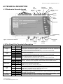
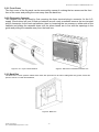
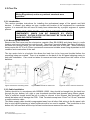
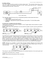
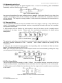
FireTrax VFT-P Engineer / Instillation Manual VI 51.1 FIRETRAX PROFESSIONAL CONVENTIONAL FIRE ALARM CONTROL PANEL Engineer / Installation Manual Printed : 04/01/2010 Doc : PROFESIONAL Engineer VI 51.1.doc -1 - FireTrax VFT-P Engineer / Instillation Manual VI 51.1 Ventcroft Ltd VFT-PFP 1/2/4/6/8Conventional Fire Alarm Control Panel Engineer / Installation Manual First Printed: 09/03/03 Document : PROFESIONAL Engineer VI 51.1 Revision: Rev 01 Last Revised : 12/4/03 Copyright © 2003 by Ventrcroft Ltd. All rights reserved. No part of this manual may be reproduced or transmitted in any form or by any means, electronic or mechanical, including photocopying, recording, or by any information storage or retrieval system, without prior written permission from the publisher. Notice of Liability Every effort has been made to ensure that this manual / instructions contains accurate and current information. However, Ventcroft Ltd shall not be liable for any loss or damage suffered by the readers as a result of information held herein. Trademarks. Ventcroft and the Ventcroft logo / device are trademarks of Ventcroft Ltd. All other trademarks are acknowledged as trademarks of their respective companies. Ventcroft Ltd Goddard Road Astmoor Industrial Estate Runcorn, Cheshire, WA7 1NQ, United Kingdom Tel: +44 (0)1928 581098 Fax: +44 (0)1028 581099 Email: [email protected] Web: http://www.ventcroft.co.uk If you have a questions about this product please do not hesitate to ring, Technical Help: +44 (0)1928 581098 Printed : 04/01/2010 Doc : PROFESIONAL Engineer VI 51.1.doc -2 - FireTrax VFT-P Engineer / Instillation Manual VI 51.1 Table of Contents 1.0 DESCRIPTION ........................................................................................................................... 4 2.0 FEATURES ................................................................................................................................ 4 3.0 KIT CONTENTS ......................................................................................................................... 4 4.0 TECHNICAL DESCRIPTION...................................................................................................... 5 4.1 Electronics Cassette Layout .................................................................................................... 5 4.2 Fire Panel Field Terminals Description .................................................................................... 5 4.3 Front mounted LED Descriptions............................................................................................. 6 4.4 External Controls ..................................................................................................................... 6 4.4 Internal Controls ...................................................................................................................... 7 4.5 Internal Features (Inside Electronics Cassette) ....................................................................... 7 4.6 Internal Safety Fuses and Current Limiting.............................................................................. 7 5.0 Installation .................................................................................................................................. 8 5.1 System Design ........................................................................................................................ 8 5.2 Fire Control Panel Enclosure................................................................................................... 8 5.3 First Fix.................................................................................................................................. 10 5.4 Pre-Connection Checks......................................................................................................... 13 5.5 Commissioning ...................................................................................................................... 14 6.0 Programming ............................................................................................................................ 17 6.1 Overview of the panel’s external controls. ............................................................................. 17 6.2 Enabling Engineer Options .................................................................................................... 18 6.3 Programming Repeater Panels. ............................................................................................ 19 7.0 Fault Finding............................................................................................................................. 20 7.1 Fault Overview....................................................................................................................... 20 7.2 Detailed Fault Finding............................................................................................................ 21 Appendix......................................................................................................................................... 24 i: Stand-by battery calculation guide............................................................................................ 24 ii: EOL Devices ............................................................................................................................ 25 iii: Detector Base and Call Point Wiring Information. ................................................................... 26 iv: System Configuration Data ..................................................................................................... 27 8.0 Specifications. .......................................................................................................................... 28 Printed : 04/01/2010 Doc : PROFESIONAL Engineer VI 51.1.doc –3– FireTrax VFT-P Engineer / Instillation Manual VI 51.1 1.0 DESCRIPTION The Professional range of conventional fire alarm control panels has been designed to be fully compliant with EN54-2:1997 and EN54-4:1997 and provide 1 to 8 zones of detection. 2.0 FEATURES The main features of the panel include: One, two, four, six or eight zones of detection (Model Dependant) Two conventional sounder circuits, fully monitored 1 Amp total sounder current Single 12V battery backup operation (With space for 2 x 7AHr VRLA batteries) Class Change Keypad access code with Keyswitch option Keypad Disable Programmable non-latching zone for networking Fire or Fault Relay Fully monitored fire output One man walk test feature Current saving zone disable Zone Short equals Fire option Electronics Cassette Metal Back Box (33 x 20mm Cable Entry Holes) Head Removal Detection (Requires Schottky Diode Bases) 3.0 KIT CONTENTS Contents 1 x 1-8 x 3 x 1 x 1 x 1 x 1 x 1 x 1 x Professional Firetrax Conventional Control Panel 10µF 36v End of Line Capacitors 6K8Ω End of Line Resistors Engineer/Installation Manual User manual/Log Book Quick Start Engineer Guide Quick Start User Guide Battery Leads Spares Kit Comprising Of:1 x 20mm Fuse 2 x 10µF 36v End of Line Capacitor 2 x 6K8Ω End of Line Resistors 1 x 470Ω Resistor 2 x Battery retainers Printed : 04/01/2010 Doc : PROFESIONAL Engineer VI 51.1.doc –4– FireTrax VFT-P Engineer / Instillation Manual VI 51.1 4.0 TECHNICAL DESCRIPTION 4.1 Electronics Cassette Layout Zone Inputs Fire Output Alarm Outputs Repeater Connections Relay Output Class Change Auxiliary Power Supply Access Jumper Relay Jumper Keyswitch Programming Pins Figure 1: Electronics Cassette A.C. Input Battery Short Terminals = Fire Battery Fuse 4.2 Fire Panel Field Terminals Description Section ZONE 1-8 ALARM 1-2 FIRE OUTPUT RELAY OUTPUT REPEATER CLASS CHANGE AUX 24V AC 12V BATTERY Legend + Terminal Numbers 1,4,6 etc - 2,5,7etc + + N/O 3,8,13 etc 21,24 22,25 23 27 28 29 30 C N/C 0v DATA +24v CC 0V 31 32 33 34 35 36 37 +24V 38 ~ ~ + 39 40 41 42 - 43 Printed : 04/01/2010 Doc : PROFESIONAL Engineer VI 51.1.doc Zone 1 Latch Engineer Button Keypad Access Description The zone terminals + and - are used to connect to either manual or automatic fire detection devices such as manual call points or smoke detectors and are fully monitored for open/short circuit and detector head removal. The terminal is used to connect the drain or cpc core of the screened cable. The Alarm terminals + and – are used to connect fire sounders and are fully monitored for open/short circuit detection. The terminal is used to connect the drain or cpc core of the screened cable. The Fire Output terminals + and – are used to connect external warning or routing devices and are fully monitored for open/short circuit detection. The terminal is used to connect the drain or cpc core of the screened cable. These are volt free contacts capable of switching 3 Amps @ 30VDC or 3 Amps @ 125VAC. This relay can be configured to switch on either a Fire or Fault activation. These connections are for the external repeater panels, up to 8 repeater panels (Active or passive) can be connected to this system. NOTE: this may affect the standby battery time. A switched 0v will allow a remote source to operate the sounders. The AUX 24v terminals provide a 24v polyfused output to drive external devices. Please check with the specifications for the maximum supply current. NOTE: this may affect the standby battery time. The ~ terminals are used to connect the 17v A.C. from the mains transformer The terminal is used to connect the Earth wire. These connections are pre-wired to a removable 3 way terminal block. The battery terminals are use for connection to the standby backup battery. These connections are already pre-wired to a removable 2 way terminal block. –5– FireTrax VFT-P Engineer / Instillation Manual VI 51.1 4.3 Front mounted LED Descriptions 4.3.1 LED Display Types Quick Reference Guide The Professional Fire Panel has various status LED’s to provide user feedback on the status of the fire panel. The Green LED is relating to the condition of the power supply, Red LED’s so if the fire panel is in a fire condition and the Yellow LED’s show Fault, Test or Disablement. FAULT/TEST/DISABLED FIRE 4.3.2 LED Descriptions LED Colour Green Power Yellow Access Red Fire Red Zones(1-8) Red Fire Output Yellow General Fault Yellow Repeater Auxiliary Supply Yellow Yellow Power Supply Yellow System Fault Yellow Zones (1-8) Yellow Test Yellow Disabled Yellow Earth Yellow Alarm Yellow Fire Output Description Status of the power supply Code Entry/ Access Level 2 Granted Fire Detected on one of the zones Zone in Fire Fire Output operated Fault Detected on one of the features below Communication Lost with repeater panel, or in setup mode Auxiliary supply fault Power Supply fault, 24V, 16V, 13.8V, 5V, Battery or Mains Supply System Fault detected. System or Site data corrupt Zone in Fault, Test or Disabled or currently being set-up A zone has been put in Test or currently being set-up A zone has been Disabled or currently being set-up Earth fault has been Detected or Disabled or currently being set-up Sounders fault Detected/Disabled or currently being set-up Fire Output Fault Detected/Disabled or currently being set-up 4.4 External Controls There are several buttons which control the operation of the fire panel on the front of the fire panel case. These controls are available from various levels: Level 1 or Level 2 (User Access) 4.4.1 Button Descriptions Button Description Silence/Activate Silence/ Activate the Sounders. (Level 2) Sounders Mute Panel Mute the internal buzzer in either fire or quiescent mode and in any access Buzzer level. Reset System This key will reset the fire panel from either a fire or a fault condition. (Level 2) Disable/Next/1 Enter Disablements mode/Scroll through options/Code Entry Test/Toggle/2 Test Display or Enter Test mode/Toggle feature/Code Entry Accept/3 Accept feature/Code Entry Code/Exit/4 Initiate Code entry/Exit out of Option/Code Entry Keyswitch Keyswitch to Enable Access Level 2 (Optional) Printed : 04/01/2010 Doc : PROFESIONAL Engineer VI 51.1.doc –6– FireTrax VFT-P Engineer / Instillation Manual VI 51.1 4.4 Internal Controls The following controls are only available from access level 3 (Engineer Access) 4.4.1 Jumper/Button Descriptions Control Description Engineer Button This is used to set-up the repeater panels. Access Jumper Enables the bypass of code entry for level 2 access Selects the action of the onboard relay from Fire or Fault Relay Jumper activation Zone 1 Latch Enables Zone 1 to be latching or Non-Latching Keypad Access Enables or Disables Access to Level 2 via the keypad code entry Globally enables a short on a zone to give a Fire not Fault Short = Fire activation. ‡ Please read relevant notes as this option may change EN54 compliance. Notes See Section 6.2.1 6.2.2 6.2.3‡ 6.2.4 6.2.5 6.2.6‡ 4.5 Internal Features (Inside Electronics Cassette) 4.5.1 Internal Buzzer This buzzer will operate during a fire, fault and test. The buzzer may be muted by pressing the Mute Buzzer button, this will silence all current activations, and the buzzer will resound on subsequent activations. 4.5.2 Internal Relay This relay is selectable between Fire and Fault output via a jumper (See Internal Controls above). 4.6 Internal Safety Fuses and Current Limiting The Firetrax Professional fire control panel has seven internal safety fuses to protect the sensitive electronics from external current overloads short circuits and thermal transformer fuse to conform regulation to limit any change of overload and fire. 4.6.1 F1: Battery, 6.3A, Anti Surge / Timed. The battery fuse protects the Firetrax battery supply from overload either while charging, standby or mains fail conditions. 4.6.2 F2: Auxiliary Supply Fuse, 100mA Polyfuse (Resetable) The auxiliary supply is protected by a 100mA polyfuse. This will be tripped when excess current is drawn through the device and will automatically reset when the fault has been removed. 4.6.3 F3: Fire Output fuse, 100mA Polyfuse (Resetable) The Fire Output is protected by a 100mA polyfuse. This will be tripped when excess current is drawn through the device and will automatically reset when the fault has been removed. 4.6.4 F4: Mains Fuse, 1 Amp 240V HRC ceramic 20mm The Mains fuse protects the Firetrax equipment from external short circuits of faults which could cause the fire panel damage. 4.6.5 F5: Mains Transformer Thermal Fuse, 1A, 102 OC. (Non Replaceable.) The Mains Transformer Thermal Fuse protects the transformer from overheating. The chance of this fuse blowing or breaking is very rare and highly unlikely and is circuit protection is mandatory and is non-replaceable. 4.6.6 Current Limiting: Alarm Outputs 500mA per Circuit Both of the alarm outputs are current limited to 500mA each and will automatically reset once the short circuit has been removed. Printed : 04/01/2010 Doc : PROFESIONAL Engineer VI 51.1.doc –7– FireTrax VFT-P Engineer / Instillation Manual VI 51.1 5.0 Installation 5.1 System Design This manual does not cover the design of a fire alarm system. Although it is assumed that you have a basic knowledge of fire system components and there correct usage before attempting to install this fire panel. It is recommended that the design of the fire system should be completed by a qualified person and that the final system is commissioned and serviced in accordance to the specifications and national standards. It is also recommended that you read BS 5839-1:2000 “Fire Detection and Alarm Systems for Buildings (Code of Practice for System Design, Installation and Servicing)” which is available at your local reference library or may be purchased from the BSI. 5.2 Fire Control Panel Enclosure The Fire panel consists of three parts, the front cover, the electronics cassette and the metal back box. As shown below. Front Cover Back Box Electronics Cassette Figure 2: Exploded view of Fire Panel NOTE: The panel must be installed internally in such a position that it will not be affected by surrounding conditions, e.g. Extremes of Temperature, Damp, water, physical abuse, etc. Ideally it should be mounted with the LED indicators at eye level in a prominent position were it is easily accessible. Typical locations are in the entrance hallway or foyer of a building or a security office that is permanently manned these being locations were the emergency services will go to first. Printed : 04/01/2010 Doc : PROFESIONAL Engineer VI 51.1.doc –8– FireTrax VFT-P Engineer / Instillation Manual VI 51.1 5.2.1 Front Cover The front cover of the fire panel can be removed by means of undoing the two screws on the front face of the cover and pulling the cover away from the back box. 5.2.2 Electronics Cassette The cassette can be removed by first removing the three terminal plug-in connector for the A.C. supply (See bottom left) and if back-up batteries are all ready connected remove the two terminal plug-in connector for the back-up batteries, then by loosening the two screws on either side of the cassette and sliding the cassette down until the screw heads are in line with the openings in the guide and pulling the cassette away from the back box. Figure 3: A.C. Input Terminal Block Figure 4: Electronics Cassette and back box 5.2.3 Back Box The back box is 1.2mm powder coated zintec steel, with provision for 33 20mm cable gland entry points; it also has space to house 2 x 7AHr SLA batteries, Figure 5: Back box Printed : 04/01/2010 Doc : PROFESIONAL Engineer VI 51.1.doc –9– FireTrax VFT-P Engineer / Instillation Manual VI 51.1 5.3 First Fix All wiring should conform to BS5839-1:2002 and BS7671:2001 (Wiring Regulations) and to any national standards were applicable. 5.3.1 Introduction This section provides instructions for installing the professional range of fire panels and field devices. It doesn’t give advice on type, number and location of the equipment for a particular system; it is assumed this will have all ready been determined by a project engineer or system planner. NOTE: THE FIRE PANEL AND FIELD DEVICES USE CMOS COMPONENTS, WHICH CAN BE DAMAGED BY STATIC DISCHARGE. SUITABLE PRECAUTIONS MUST BE TAKEN WHEN HANDLING CIRCUIT BOARDS. 5.3.2 Mounting the Back Box Remove the front cover and the electronics cassette (See 5.2.1-5.2.2) and place them in a safe location, and mount the back box onto the wall. There are 5 mounting holes (see figure 6 below) in the back box through which you can securely mount the back box to the wall. These mounting holes require No.10-12 or 5-5.5mm countersunk screws and suitable screw fixing dependant on the condition and construction of the wall. The top centre hole is a keyhole this allows the back box to be hung and levelled before the remaining holes are marked. There is a template on the back of the fire panel shipping carton to help with installation. Care must be taken to remove and dust and swarf from the interior of the back box. Figure 6: Back box mounting holes Figure 7: Knockouts for mains use Figure 8: How to remove knockouts 5.3.3 Cable Installation Cables should be in accordance with BS5839-1:2002, they should be brought into the back box through the top, bottom, left, right or rear knockouts provided and glanded using 20mm glands. Tails of sufficient length should be left in order to connect to the relevant field terminals. Care should be taken not to damage the PCB. Field Terminals accept one 0.5mm2 to 2.5 mm2 stranded or solid conductor cable. The Mains supply cable should be segregated away from all other field wiring in the fire panel, with this in mind careful planning of what knockouts are to be used is needed. The knockouts on the bottom left, left hand side and the top left two knockouts are reserved for mains cable. Printed : 04/01/2010 Doc : PROFESIONAL Engineer VI 51.1.doc – 10 – FireTrax VFT-P Engineer / Instillation Manual VI 51.1 5.3.4 Mains Wiring The mains supply should be exclusive to the fire alarm panel. This should be fixed wiring using three core cable or equivalent(not less than 0.75 mm2 and not more than 25 mm2 ), fed from an isolating switched fuse spur, fused at 3A. Figure 9: Mains Wiring This fused spur should be secure from unauthorised operation and be marked with either: “FIRE ALARM” “FIRE ALARM. DO NOT SWITCH OFF” “WARNING. THIS SWITCH ALSO CONTROLS THE SUPPLY TO THE FIRE ALARM SYSTEM” 5.3.5 Detector and Manual Call Point Wiring Field Devices should be wired with a minimum of 1mm2 copper cables, there should be no spurs, or ‘T’ offs from the main run. NOTE: Please refer to the specification for the maximum number of devices that may be fitted to each zone. Figure 10: Zone wiring example 1 Figure 11: Zone wiring example 2 The EOL Device must be connected across the terminals of the last device on each zone to enable head removal detection. Detector bases with integrated continuity diode to ensure manual call points will continue to work when a detector head is removed from its base (Please see note below). Manual call points with integrated resistors (470-680Ω) must be used in order to prevent an activation being processed as a fault instead of a fire condition. (See Appendix IV for various connection details). Please refer to manufactures instructions for more detailed wiring diagrams. NOTE: Although it is possible to connect both automatic (Smoke detectors) and manual (Call points) activation devices to the zones it is recommended that these different types are kept on individual zones. Figure 12: Zone wiring example 3 The wiring for each zone should be connected to the relevant terminal on the control panel and their screens connected to the terminal. NOTE: Please observe the polarity of the connections. Printed : 04/01/2010 Doc : PROFESIONAL Engineer VI 51.1.doc – 11 – FireTrax VFT-P Engineer / Instillation Manual VI 51.1 5.3.6 Networking with Zone 1 In order to network multiple fire panels together Zone 1 is set to non-latching (See 4.4 Internal Controls), and the following circuit is used:- Figure 13: Zone1Network Wiring As soon as the auxiliary fire relay contacts close on panel B it will cause Panel A to go into a fire condition immediately, when the fire condition on Panel B is cleared the fire condition on Panel A will be cleared. This stops the lockup problem if both panels are networked with connections in both directions. 5.3.7 Sounder Wiring Two conventional sounder circuits are available which can supply a total of 1 Amp (500mA per circuit). All sounders must be polarised versions; non-polarised sounder will show as a sounder fault on the control panel. A 6k8Ω resistor must be fitted in the last sounder in each of the alarm circuits to enable correct monitoring of the alarm circuits. Please refer the manufactures instructions for details wiring descriptions. Figure 14: Sounder Wiring The wiring for each alarm circuit should be connected to the relevant terminal on the control panel and their screens connected to the terminal. Note: Please observe the polarity of the connections. A relay may be connected on the sounder circuit providing that two diodes are fitted as shown below. The relay must have a 24V DC coil. Note: EN 54-4:1998 states that all sounder output circuits must be monitored by adding this relay you will bypass this fault monitoring. Figure 15: Sounder wiring with Additional relay output 5.3.8 Fire Output Wiring The fire output circuits can supply a total of 100mA. Any external devices connected to the fire output must be polarised; non-polarised devices will show as a fire output fault on the control panel. A 6k8Ω resistor must be fitted in the last device in the fire output circuit to enable correct monitoring of the circuit. Figure 16: Example of a relay connected to the fire Output Printed : 04/01/2010 Doc : PROFESIONAL Engineer VI 51.1.doc – 12 – FireTrax VFT-P Engineer / Instillation Manual VI 51.1 5.3.9 Relay Output Wiring A volt free set of relay contacts are available for switching various external devices. These are able to switch up to 3 Amps @ 30VDC or 3 Amps @125VAC. This relay can be configured to switch state on either fire activation or fault activation via a jumper (See 4.4 Internal Controls). Figure 17: Example of a SD1 speech dialler connected to the fire Output 5.3.10 Class Change Wiring If this terminal is wired to an auxiliary 0V it will cause the sounders to active continuously while the connection is applied. The Fire Output will not be activated. Figure 18: Example of a timed contact connected to the class change inputs 5.3.11 Repeater Wiring Up to eight active/passive repeaters may be added to the fire control system. Figure 19: Example of repeater panel wiring 5.3.12 Auxiliary 24V This provides a 24V supply for external loads; it is able to supply a maximum of 100mA. Any current drawn from this auxiliary supply must be taken in to account when calculating the standby battery size. Note: It is not recommended to power door closures from these terminals 5.4 Pre-Connection Checks Before connecting to the panel all wiring should be checked, the field wiring should be checked for insulation, continuity, earth faults and short circuits etc. Connect the EOL capacitor (End of Line) across the last device in each of the zone wiring runs and the EOL resistor across the sounder circuits and fire output runs. Then connect all field devices, once connected DO NOT USE A HIGH VOLTAGE MEGGER to test the circuitry; only low voltage meters or equivalent should be used. Using a multi-meter verify that all zone, sounder and fire output circuits EOL devices can be seen. If a zone, sounder or fire output circuit is not used the EOL device should be left fitted in the panel field terminals. Printed : 04/01/2010 Doc : PROFESIONAL Engineer VI 51.1.doc – 13 – FireTrax VFT-P Engineer / Instillation Manual VI 51.1 5.5 Commissioning WARNING: Damage may occur by connecting cables to the panel while the panel is powered. Ensure this section has been read and understood before attempting to commission the panel. 5.5.1 Introduction Commissioning the fire panel involves the following procedures: Connecting Field devices and external wiring Configuring hardware settings Powering the panel Testing the system In order to avoid unnecessary problems this procedure should be completed in a logical step by step order and each step being verified that it is correct before attempting the next step. Before connecting the field devices, it is recommended that the panel is powered up and checked for correct operation. 5.5.2 Connecting the Mains Before starting ensure that the fire panel back box is earthed and that the mains supply is isolated. The incoming mains cable should be brought through the back box by either the bottom left hand knockouts, top left hand side knockouts or by top left knockout (See 5.3.3). This should then be terminated to CON1 at the left of the transformer. (See figure 21) Figure 21: Example of mains wiring. Figure 20: Recommended mains entry points. Printed : 04/01/2010 Doc : PROFESIONAL Engineer VI 51.1.doc – 14 – FireTrax VFT-P Engineer / Instillation Manual VI 51.1 5.5.3 Connecting the back-up batteries The professional series of fire panels only requires a single 12v sealed valve regulated lead acid battery in order to maintain correct working. A new fully charged battery should be fitted in the back box as shown below left. The plug-in connector with the battery leads should be removed from the electronics cassette and the battery leads connected to the backup battery (Please ensure that the polarity of the leads are correct). Figure 22: Example of a single 7.0 AHr battery Figure 23: Example of two 7.0 AHr batteries The fire panel incorporates a sophisticated battery charge and monitoring circuit, this ensure correct charging over varying temperatures and prevents deep discharge of the battery in mains fail condition. If a battery is not fitted, discharged or damaged the fire panel will show a PSU fault. The capacity of this battery will depend upon the stand-by time, to calculate this battery capacity please refer to Appendix i. If you require a larger capacity than then two of the same capacity batteries can be placed in parallel. NOTE: Please ensure if two batteries are used that they are from the same manufacturer and have the same capacity. 5.5.4 Connecting the Electronics Cassette Ensure all EOL devices are in place for the zones, sounder and fire output circuits. Place the electronics cassette up to the back box lining up the holes in the guide rails with the bolts in the back box. 5.5.5 Initial Power Up and Test 1. Connect the three terminal plug-in A.C. connector into the electronics cassette. 2. Switch on the Mains supply 3. All LED’s should light and the internal buzzer will sound 4. Only the Power (Flashing), General Fault and the PSU Fault should remain lit. 5. The internal Buzzer will still be sounding. NOTE: This may be muted by pressing Mute Panel Buzzer. 6. If any other LED’s are lit or abnormal conditions indicated, these should be investigated and rectified before proceeding. See 7.0 Fault Finding. 7. Connect the two terminal plug-in Battery connector into the electronics cassette. 8. The Power Led should go constant and the General and PSU fault LED should go out. 9. If any other LED’s are lit or abnormal conditions indicated, these should be investigated and rectified before proceeding. See 7.0 Fault Finding. 10. Switch of the Mains Supply and remove the Battery plug-in connector. Printed : 04/01/2010 Doc : PROFESIONAL Engineer VI 51.1.doc – 15 – FireTrax VFT-P Engineer / Instillation Manual VI 51.1 5.5.6 Connecting the Detectors 1. Remove the EOL device from the first Zone terminals, and connect it to the last device on that Zone. (Please observe the polarity: See Appendix ii – EOL Devices). 2. Connect the external wiring into the zone terminals in the control panel (Please observe correct polarity for zone and connect the screen to the terminal) 3. Check correct operation of control panel follow procedure 5.5.5 above. 4. Repeat steps 1-3 for each of the zones to be connected, if any zones are left unused leave the EOL device in the zone terminals in the control panel. 5.5.7 Connecting the Sounder Circuits 1. Remove the EOL device from the first Alarm terminals, and connect it to the last device on that circuit (Please observe the polarity: See Appendix ii – EOL Devices). 2. Connect the external wiring into the Alarm terminals in the control panel (Please observe correct polarity for zone and connect the screen to the terminal) 3. Check correct operation of control panel follow procedure 5.5.5 above. 4. Repeat steps 1-3 for the other Sounder circuit. 5.5.8 Connecting the Fire Output Circuit 1. Remove the EOL device from the Fire Output terminals, and connect it to the last device on that circuit (Please observe the polarity: See Appendix ii – EOL Devices). 2. Connect the external wiring into the Fire Output terminals in the control panel (Please observe correct polarity for zone and connect the screen to the terminal) 3. Check correct operation of control panel follow procedure 5.5.5 above. 5.5.9 Connecting the Relay 1. Connect the external wiring to the required terminals (N/O, C, N/C). Please ensure you do not exceed the current rating of the relay contacts 2. Check correct operation of control panel follow procedure 5.5.5 above. 5.5.10 Connecting Repeater Panel 1. Connect the external wiring to the repeater terminals (0V, DATA, 24V). Please ensure the connections are correct. 2. Check correct operation of control panel follow procedure 5.5.5 above. 5.5.11 Connecting Class Change 1. Connect the external wiring to the required terminals (CC, 0V). Please ensure that a volt free switch or contact is used. 2. Check correct operation of control panel follow procedure 5.5.5 above. 5.6 Replace the Front Panel Ensure all the jumpers are in the correct positions and the Access jumper is in the keeper position. If the electronics cassette has been lowered to aid cable installation this should be pushed up to its top position and the two bolts tightened. The front panel can now be replaced and the final two bolts tightened up. Printed : 04/01/2010 Doc : PROFESIONAL Engineer VI 51.1.doc – 16 – FireTrax VFT-P Engineer / Instillation Manual VI 51.1 6.0 Programming 6.1 Overview of the panel’s external controls. On the professional range of fire panels there are three levels of access: Level 1 (General User ) Level 2 (Authorised User ) Level 3 (Engineer) The functions of each of these levels are detailed below. 6.1.1 General User (Access Level 1) This is the normal state for the fire panel, the LED’s give a complete overview of the current status of the system; the display clearly shows any zones in fire or fault condition as well as any zones or outputs that are currently disabled or in test. The only functions that are available at this level are: Mute the panel buzzer Test the Led display and panel buzzer Code Entry to gain Level 2 access 6.1.2 Authorised User (Access Level 2) Access to this level of controls is limited via entering the code 2143 (or turning the keyswitch to the ON position); this is required to stop unauthorised changes to critical functions of the fire alarm. The following functions are available at this access level: Silence the sounders Resetting the panel from a fire condition Manually activating the sounders (To perform a routine test or evacuate the building) Putting/Removing a zone from test Disabling/Enabling any (or all) of the following: Zones, Earth faults, Sounders or the Fire output For details on the above functions and there correct operation please refer to the USER GUIDE. 6.1.3 Engineer (Access Level 3) Access to this level is gained by the removal of the front cover. The following controls should only be changed by competent service personnel. Override Access Required Relay Activation Selection Zone 1 Latching/Non-Latching Keypad Access Disabled Short=Fire Enabled Program Repeater Panels The following section will detail the above features and how they can be enabled or disabled. Printed : 04/01/2010 Doc : PROFESIONAL Engineer VI 51.1.doc – 17 – FireTrax VFT-P Engineer / Instillation Manual VI 51.1 6.2 Enabling Engineer Options 6.2.1 Engineer Button This button allows the engineer to enter engineer mode. And will scroll through the available options. 6.2.2 Access Jumper This is a two position jumper which gives the engineer the option to bypass the need to enter the user code to gain access to Level 2. This is useful during the commissioning of a fire panel. This jumper can be used to permanently enable the keypad while the engineer is working on the fire panel. NOTE: This jumper must be ACCESS placed back in the keeper position before the fire panel cover is Access replaced. Jumper This is the default place for this jumper, and must be replaced here KEEPER before the panel installation is finished. 6.2.3 Relay Jumper This jumper controls the function of the onboard relay; the relay can be switched on either a fire condition or a fault condition. With the jumper in this position the relay will be de-energised during a FIRE fire condition. Relay With the jumper in this position the relay will be de-energised during a Jumper FAULT fault condition. NOTE: To comply with EN54 the jumper must be in this position. 6.2.4 Zone 1 Latch This jumper controls the facility to turn zone 1 from latching to non-latching. This jumper makes zone one a latching fire zone or a non-latching fire ON zone. Non-latching zones can be used for networking multiple fire Zone 1 panels together. Latch OFF Zone 1 acts as a normal latching fire zone. 6.2.5 Keypad Access This jumper can be used to disable code entry from the keypad; you must have the keyswitch option fitted to the panel to be able to use this option. This enable level 2 access by either keypad code entry or via the ON keyswitch (if fitted) Keypad Access This jumper disables keypad code access to level 2 of the fire panel. OFF This function must only be used were the keyswitch option is fitted. 6.2.6 Short=Fire This jumper enables the use of older style smoke detectors which present a short it fire condition not the usual resistance load. This option is used when the panel is connected to old style smoke ON detectors that apply a short to the zone in fire condition. This option is global to all the zones. Short = Fire The Fire zones act as normal: A short on a zone produces a fault condition A 230Ω to 680Ω generates a Fire condition. OFF NOTE: To comply with EN54 the jumper must be in this position. Printed : 04/01/2010 Doc : PROFESIONAL Engineer VI 51.1.doc – 18 – FireTrax VFT-P Engineer / Instillation Manual VI 51.1 6.3 Programming Repeater Panels. The following section will detail the programming and reviewing of repeater panels to the main fire control panel. LED Buttons The Following Controls are used:Control Action Description Engineer Pressed Scrolls through the available Engineer options Press to enter into Repeater Program mode, Learn Mode or Review Accept Pressed Mode To scroll the options in Repeater Program mode (Learn or Review Toggle Pressed mode) Exit Pressed To Exit out of either of the Programming modes (Learn or Review) ON In Engineer Mode, press accept to enter into Repeater Program Mode 7 Off / 1 On Learn Mode: Press ACCEPT to enter into Learn mode Repeater 7 On / 1 Off Review Mode: Press ACCEPT to enter into Review mode 1 On / 1 Off In Review Mode: Press EXIT to return to Engineer options 6.3.1 Repeater Learn Mode 1. Press Engineer button until the repeater LED is illuminated 2. Press the TOGGLE until the Learn mode is selected (Learn Mode = Repeater LED will flash 7 OFF/1 ON) 3. Press ACCEPT to enter Learn Mode. 4. The panel will then search for Repeater Panels connected to the fire control panel. a. If the panel finds any repeater panels it will give 2 beeps and advance back to Engineer options with Review mode highlighted. b. If no repeaters are found the panel will give a long beep and return to Engineer options with Learn mode highlighted. 5. Press EXIT to leave Engineer options. 6.3.2 Repeater Review Mode 1. Press Engineer button until the repeater LED is illuminated 2. Press the TOGGLE until the Review is selected (Review Mode = Repeater LED will flash 7 ON/1 OFF) 3. Press ACCEPT to enter Review Mode. 4. The repeater LED will then flash 1 ON/1 OFF to display your in Repeater Review Mode. 5. If any repeaters have been programmed into the fire control panel the Fault LED on zone 1 will illuminate. 6. Zone 1 Fire LED will then flash to show the number of repeaters currently programmed into the fire control panel followed by a 5 second gap before repeating then number of programmed repeaters. 7. Press EXIT to return to Engineer options. 8. Press EXIT to leave Engineer options. 6.3.3 Check All Repeaters After programming the fire control panel with repeater panels you should review the number of repeater panels that the system has programmed in corresponds to the number of repeater panels you have installed. If there is a discrepancy check that each of the repeater panels are not showing any communication faults. Printed : 04/01/2010 Doc : PROFESIONAL Engineer VI 51.1.doc – 19 – FireTrax VFT-P Engineer / Instillation Manual VI 51.1 7.0 Fault Finding When the fire control panel detects a fault in a critical part of the system it will illuminate the General Fault and the corresponding Fault LED, the internal buzzer will sound and if configured the fault relay will activate. The following section will give a brief overview of the faults followed by a detailed description and solutions for remedying the fault. Upon detection of a fault the internal buzzer may be silenced from any Access Level by pressing the Mute Panel Buzzer button (see 4.5.1). All faults with the exception of a mains fault are latching faults requiring a panel reset, mains faults will automatically be reset when the fault is removed. 7.1 Fault Overview The following section gives a brief overview of system faults. 7.1.1 General When the fire control panel detects a fault within the system, the General Fault LED will start to flash along with the corresponding fault LED. 7.1.2 Zone All of the zones on the fire control panel are constantly monitored for head removal, open and short circuit. Once a fault is detected on a zone the relevant zone fault Led will illuminate (Unless the zone is in test or has been disabled). See 7.2.1 for detailed Zone fault finding 7.1.3 Repeater This Led illuminates when the fire control panel cannot communicate to one or more of the repeater panels. See 7.2.2 for detailed repeater panel fault finding 7.1.4 Auxiliary This Led illuminates when either too much current is drawn or the auxiliary supply is shorted out. See 7.2.3 for detailed Auxiliary power supply fault finding 7.1.5 Power Supply The Power supply fault Led illuminates when there is a fault on the battery charge circuit, 24/28V supply,16V supply, 13.8V supply, or the 5v supply or when the battery or mains is removed. See 7.2.4 for detailed Power Supply fault finding 7.1.6 System The system fault illuminates when there is one of the following faults: - Watchdog timeout, Site or program memory has become corrupted, or there is a fault on the fire control panel circuit board. See 7.2.5 for detailed System fault finding 7.1.7 Earth This fault will occur when a connection is made between earth and one of the transmission paths to the fire control panel. See 7.2.6 for detailed Earth fault finding 7.1.8 Sounder Output This illuminates if a fault is detected on one of the sounder circuits either open or short circuit. These are constantly monitored in quiescent and in fire alarm condition. See 7.2.7 for detailed sounder Output fault finding Printed : 04/01/2010 Doc : PROFESIONAL Engineer VI 51.1.doc – 20 – FireTrax VFT-P Engineer / Instillation Manual VI 51.1 7.1.9 Fire Output This Led illuminates when either an open or short circuit is detected on the Fire Output cabling or devices connected to the terminals. See 7.2.8 for detailed Fire Output fault finding 7.2 Detailed Fault Finding The following section gives a detailed description of the fault and the steps needed to be taken to remedy the fault. 7.2.1 Zone Faults. 1) Visually check all detectors on the zone to ensure all smoke heads are fitted and correctly seated on there bases. Replace or reseat any smoke detector heads and reset the panel, continue if fault remains. 2) Remove the wiring for that zone from the panel and refit the EOL device into the control panel zone terminals. 3) Reset the fire panel and check if the fault is removed. 4) If the fault is removed then the fault is on the wiring, continue to step 6 5) If the fault continues the fault is in the fire panel. Please contact Ventcroft Ltd. Technical Support. 6) Remove the EOL device from the control panel terminals and reconnect the zone wiring. 7) Select the first device from the fire control panel. 8) Remove the output wiring to the next device and connect your EOL device across the zone wiring (see figures 24, 25). 9) Reset the fire control panel. 10)If the fault clears go to step 13. 11)If the fault returns there is a problem with either this detector (or call point) or the wiring that connects it. 12)Check this detector and the wiring connections in the base. Go to step 14 Checking Fault Type. 13)The fault is in the subsequent wiring; remove the EOL device and replace the output wiring in the detector, go to the next detector (or call point) on the zone wiring and repeat steps 8-10 until the fault is found. To Last Device on Zone To Fire Control Panel Figure 24: Fully wire detector base Figure 25: Detector base with output wires removed and EOL capacitor fitted. Printed : 04/01/2010 Doc : PROFESIONAL Engineer VI 51.1.doc – 21 – FireTrax VFT-P Engineer / Instillation Manual VI 51.1 Checking Fault Type 14)Remove the zone wiring from the fire control panel. 15)Using a multi-meter check for continuity between the + and – wires for the zone. 16)If you get a continuity reading then there is either a short on the cable run or in the detector. If you don’t get a reading go to step 22. 17)Remove the detector head and check for continuity again. 18)If you still get a continuity reading then there is a short in either the base of the detector or in the cable connecting it. Check the wiring in the detector base and the cable run and replace which ever is necessary. Recheck continuity. 19)If you don’t get a continuity reading then the fault is in the smoke detector head, replace the head with a new one and retest. 20)The fault should have now cleared remove the EOL device from this base and reconnect the output wiring to the next detector (or Call point) and replace the EOL device in the last detector (or Call point) in the zone wiring. 21)Go to step 30 22)The fault is either an open circuit in the wiring or the detector head is not fitted properly (or faulty) 23)Short (Connect together) the zone wires in control panel (should have been removed already in step 14) 24)In the detector base check for continuity between the Positive in and the Negative in terminals. 25)If you don’t get a continuity reading then the fault is in the smoke detector head, replace the head with a new one and retest. 26)If you don’t get a continuity reading then there is a break in the cable or incorrectly fitted in the detector base. 27)Recheck the connections in the base and replace the wiring from this detector to the previous one if necessary. 28)The fault should have now cleared remove the EOL device from this base and reconnect the output wiring to the next detector (or Call point) and replace the EOL device in the last detector (or Call point) in the zone wiring. 29)Remove the short between the zone wires in the control panel and replace them into the correct terminals. 30)Reset the control panel, the fault on this zone should be cleared. If not there was more than one fault on the cable run repeat steps 1-30. 7.2.2 Repeater Panel Faults 1) Visually check all of the repeater panels connected to the fire alarm control panel 2) On the ones that show a communications error. a. Check the terminations in the repeater itself. b. Check the wiring from the main panel to the repeater. 7.2.3 Auxiliary Power Supply Faults 1) There is a short on the wiring from the auxiliary power supply terminals or the devices attached to these terminals are drawing too much current. a. Check the wiring for short circuits. b. Remove external devices until the current drawn is of an acceptable level. 7.2.4 Power Supply Faults 1) There is a problem with one of the power supplies within the fire control panel. a. Check that the mains supply is present and healthy. b. Check the Isolating Fused Spur’s fuse has not blown. c. Check the mains terminal block fuse has not blown. d. Check that the backup battery is connected and healthy. Printed : 04/01/2010 Doc : PROFESIONAL Engineer VI 51.1.doc – 22 – FireTrax VFT-P Engineer / Instillation Manual VI 51.1 e. Check the battery fuse has not ruptured. f. If the problem still persists please contact Ventcroft Ltd. Technical Help 7.2.5 System Faults 1) There is a problem with the system, the system site data or the system program code. a. Reset the system – Check if the fault is cured b. Try reprogramming a zone (i.e. disable one zone, reset the system, then reenable that zone) c. Contact Ventcroft Ltd. Technical Help 7.2.6 Earth Faults 1) There is a connection between earth and one of the transmission paths to the Fire control panel (i.e. one of the zones wiring is shorted to the building’s metal work) a. Remove all of the zone wiring, sounder wiring and any other external wiring (repeaters etc.) and replace the End of line devices in the appropriate terminals. b. Reset the fire control panel – The fault should have cleared. If not contact Ventcroft Ltd. Technical Help c. One at a time, replace the zone wiring and sounder wiring etc, resetting the fire control panel on each reconnection. d. Check of earth faults. e. Once the earth fault reappears check the wiring for that zone or sounder etc, make sure all cables and devices are free from defect and replace as necessary. 7.2.7 Sounder Output Faults 1) Remove the sounder wiring from all the sounder circuits in turn and using a multi-meter measure the resistance across the wires. You should see a reading equal to the EOL resistor any other value (e.g. zero ohms, open circuit or a reading too high or too low) indicates a fault on the wiring. 2) If all the sounder circuits’ resistance measurements are good, leave the sounder circuit wiring out of the panel sounder terminals and place the EOL resistor across each of the sounder circuits. If the fault still persists then there is a fault in the panel sounder circuitry. Please consult Ventcroft Ltd. Technical support. 3) If the sounder fault is present only during a fire alarm then the sounder circuits are drawing too much current, check that there are not too many sounders on the circuit or that all the sounders are operating correctly. Note: The sounder circuits use polyfuses to protect the outputs these will reset themselves after the short circuit has been removed. 7.2.8 Fire Output Faults 1) Remove the wiring from the fire output circuit and using a multi-meter measure the resistance across the wires. You should see a reading equal to the EOL resistor any other value (e.g. zero ohms, open circuit or a reading too high or too low) indicates a fault on the wiring. 2) If the Fire Output circuit resistance measurement is good, leave the Fire Output circuit wiring out of the panel fire output terminals and place the EOL resistor across the circuit. If the fault still persists then there is a fault in the panel Fire Output circuitry (See note below). Please consult Ventcroft Ltd. Technical support. 3) If the Fire Output fault is present only during a Fire Output then the Fire Output circuit is drawing too much current, check that there are not too many devices on the circuit or that all the devices are operating correctly. Note: The Fire Output circuit uses a polyfuse to protect the output this will reset itself after the short circuit has been removed. This may take a few seconds. Printed : 04/01/2010 Doc : PROFESIONAL Engineer VI 51.1.doc – 23 – FireTrax VFT-P Engineer / Instillation Manual VI 51.1 Appendix i: Stand-by battery calculation guide The standby time of a control panel is dependant upon the quiescent current drawn by the panel and ancillaries in mains fail, the alarm current and duration of alarm and the capacity of the standby batteries installed. The following equation should be used to calculate the size of battery to be used for any given stand-by period. Stand-by Time in AHr = 1.25 x ((TxA) + H x (Q+Z)) A de-rating factor of 1.25 is included in the equation to compensate for aging and loss of capacity in the batteries over time. T A = = H Q = = Z = Time in hours the alarm is required to ring for. (Usually being half an hour) Alarm Current. This is the total current for the sounders and any devices connected to other alarm outputs. Hours of stand-by required. Quiescent current of the panel = 0.055A (55mA) This is with the Mains failed, buzzer sounding and the Power Supply and General Fault indicators lit. If there are any other ancillary devices added to the system the quiescent current of these devices must be added to this value. Zone devices quiescent current. This value will nominally be 50µA per detector and zero for call points. The manufacturer of the zone device should be consulted for the actual value. Example 1: System has 100 detectors each with a quiescent current of 50µA, and a total sounder current of 400mA which must ring for 30 minutes, the system stand-by time required is 24 hours. T = 0.5 A = 0.4A H = 24 Q = 0.055A Z = (100 x 0.00005) = 0.005A Stand-by Battery Size = 1.25 x ((0.5 x 0.4) + 24 x (0.055 + 0.005)) = 2.05 AHr Therefore choosing the closest next size up battery capacity means this system requires: 1 x 2.1 AHr SLA battery. Example 2: System has 240 detectors each with a quiescent current of 50µA, and a total sounder current of 1 Amp which must ring for 30 minutes and the system stand-by time required is 72 hours. T = 0.5 A = 1A H = 72 Q = 0.055A Z = (240 x 0.00005) = 0.012A Stand-by Battery Size = 1.25 x ((0.5 x 1) + 72 x (0.055 + 0.012)) = 6.655 AHr Therefore choosing the closest next size up battery capacity means this system requires: 1 x 7 AHr 12v SLA battery. Printed : 04/01/2010 Doc : PROFESIONAL Engineer VI 51.1.doc – 24 – FireTrax VFT-P Engineer / Instillation Manual VI 51.1 ii: EOL Devices The Firetrax fire control panel uses two different types of End of Line device. These are Capacitors on the zones and Resistors for the Alarm outputs, and Fire outputs. Capacitor EOL Device. The capacitors used on the Firetrax fire control systems are 10µF 36V capacitor. This should be fitted in the last device on the zone between the Positive out and the Negative out (See Figure 26). This capacitor is polarised and the lead witch is connected to the Negative terminal will be denoted by a white stripe down the side of the capacitor case (See Figure 27) Figure 26: Nittan (Diode) base with Capacitor EOL Device fitted. Figure 27: Capacitor End of Line Device Resistor EOL Device. The resistors used on the Firetrax fire control systems are 6K8Ω resistors (Blue, Grey, Red, Brown). These should be fitted in the last device on the Alarm Circuits and the Fire Output circuit. To Fire Control Panel Alarm Sounder Circuits Figure 30: Close-up of a 6K8Ω Resistor EOL Device with colour bands shown. Figure 28: Vimpex Banshee Sounder with Resistor EOL Device Fitted Printed : 04/01/2010 Doc : PROFESIONAL Engineer VI 51.1.doc – 25 – FireTrax VFT-P Engineer / Instillation Manual VI 51.1 iii: Detector Base and Call Point Wiring Information. Detector Bases Manufacturer Hochiki Model YBK-R/5ZD YBN-R/4 Positive In Positive Out Negative In Negative Out Screen Remote Indicator Positive Remote Indicator Negative Head Removal Detected L1 L2 C5 C6 S3 L1 S4 Yes 1 2 5 6 3 N/A N/A No Manufacturer Model Positive In Positive Out Negative In Negative Out Screen Remote Indicator Positive Remote Indicator Negative Head Removal Supported Manufacturer Model Positive In Positive Out Negative In Negative Out Printed : 04/01/2010 Doc : PROFESIONAL Engineer VI 51.1.doc Standard STB-4 3 3 1 6 N/A 3 5 No Nittan Resistor Diode STB-4R STB-4SD 4 3 4 3 1 1 6 6 N/A N/A 3 3 5 5 No Yes Diode/ Resistor STB-4SDR 4 4 1 6 N/A 3 5 Yes Apollo Series 60/65 ORBIS Diode Common Diode Common L1 IN L1 IN IN+ IN+ L1 OUT L1 OUT OUT+ OUT+ L2 L2 COMCOML2 L2 COMCOMEARTH EARTH 4 4 L1 IN L1 IN IN+ IN+ -R -R LEDLEDYes No YES NO Detector Bases K.A.C Standard 5 5 1 2 Diode 4 4 1 2 3 1 No 3 1 Yes Ventcroft VCP RANGE IN+ OUT+ INOUT- K.A.C. 1 1 2 2 – 26 – Call Points Fulleon 470 Ohms 470 Ohms Common Common Tamtech FSGBG 3 3 2 2 CQR FP2 TB2-C TB3-A TB3-C TB3-B Ziton Standard 5 5 3 2 5 8 No FireTrax VFT-P Engineer / Instillation Manual VI 51.1 iv: System Configuration Data Fire Zone Information Zone Number 1 2 3 4 5 6 7 8 Zone Description A concise explanation of areas and rooms contained in each zone Fire Panel Input/Output Routing Information Type Of Input Connected? Class Change Type Of Output Yes No Connected? Fire Output Relay Output Yes Yes How is it connected? What Happens When Activated? No No Additional Information Any additional information the user needs to know should be entered here; Repeater locations, additional outputs routing information, etc. The information above was completed by: Name (in block letters): Position: Signature: Date: For and on behalf of: Printed : 04/01/2010 Doc : PROFESIONAL Engineer VI 51.1.doc – 27 – FireTrax VFT-P Engineer / Instillation Manual VI 51.1 8.0 Specifications. Power Supply Mains Supply Voltage Mains Fuse Output Voltage Number of Batteries required Maximum Battery size and type Batteries monitored for disconnection/failure Batteries protected against deep discharge Battery charger temperature compensated Battery Fuse Detector Circuit Number Of Zones Maximum Cable Length Zone Faults monitored Maximum Cable Resistance Maximum Cable Capacitance Maximum Number of Devices per zone Sounder Circuits Number Sounder Circuits Alarm Voltage Maximum Sounder Current Sounder Circuit Protection Sounder Circuit Faults Monitored Maximum number of bells @ 25mA Maximum number of electronic sounders @ 20mA End of line resistor value Auxiliary Outputs Fire Output End of line resistor value Relay Output (Fire/Fault Selectable) Auxiliary 24V Auxiliary 24V Circuit Protection Auxiliary Inputs Class Change 230V a.c. +10% -15% 50/60Hz 240V 1A HRC ceramic 20mm (IEC60127 pt2 compliant) 24v/28v 1 2 x 7.0AHr SLA connected in parallel (14 AHr max. capacity) YES YES (Cut off approx 10.5 Volts) YES 6.3A F 20mm (IEC60127 pt2 compliant) 1,2,4,6 or 8 model dependant 1000 meters Short, Open circuit and Detector head removal 20Ω 1µF 30 2 24v/28v d.c. 2 x 500mA = 1 Amp Each circuit has over current protection which is limited to 500mA per circuit and will automatically reset once the fault is removed. Short and Open circuit in both quiescent and alarm condition 40 (Must be polarised) 50 (Must be polarised) 6K8Ω 1% Tolerance 0.25W (Blue, Grey, Red, Brown) 100mA. Fully monitored for Open/Short Circuit 6K8Ω 1% Tolerance 0.25W (Blue, Grey, Red, Brown) Volt free contacts rated 3A @ 30Vdc or 3A @ 125Vac (N/O , Common, N/C) 24v/28v dc Auxiliary 24V circuit has over current protection which is limited to 100mA and will automatically reset once the fault is removed. 0V input will activate the sounders for the duration of the trigger signal Dimensions and Weights Physical size 340 x 282 x 118mm approximately Weight 3.3kg (without batteries) approximately Operating Conditions The Firetrax system is designed to operate within its specification as long as the environmental conditions outside the enclosure comply with class 7k5 of IEC 721-3-3:1978. -5 to +400C Printed : 04/01/2010 Doc : PROFESIONAL Engineer VI 51.1.doc – 28 –


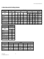
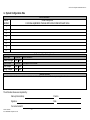


![AWD10SS [obsolete] User Manual](http://vs1.manualzilla.com/store/data/005777265_1-bc3e4afb4b891fb2fe3c32a930faa0e5-150x150.png)