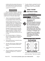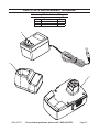
1
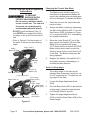
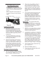
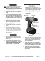
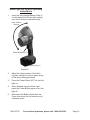
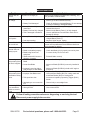
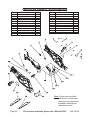
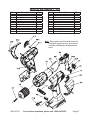
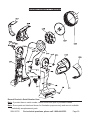
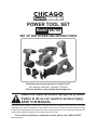
Power TOOL set
Model 66755
Set up and Operating Instructions
Distributed exclusively by Harbor Freight Tools®.
3491 Mission Oaks Blvd., Camarillo, CA 93011
Visit our website at: http://www.harborfreight.com
Read this material before using this product.
Failure to do so can result in serious injury.
Save this manual.
Copyright© 2009 by Harbor Freight Tools®. All rights reserved. No portion of this manual or any artwork
contained herein may be reproduced in any shape or form without the express written consent of Harbor
Freight Tools. Diagrams within this manual may not be drawn proportionally. Due to continuing improvements,
actual product may differ slightly from the product described herein.
For technical questions or replacement parts, please call 1-800-444-3353.
Manual Revised 09l
Contents
Important SAFETY
Information���������������������������������3
General Power Tool Safety
Warnings������������������������������������������� 3
Reciprocating Saw Set Up and
Operating Instructions����������� 16
Installing the Saw Blade������ 16
Operating the
Reciprocating Saw���������������� 16
Plunge Cutting������������������������������� 17
Circular Saw Safety Warnings� 5
Metal Cutting���������������������������������� 17
Drill Safety Warnings������������������� 7
Drill/Driver Set Up and
Operating Instructions����������� 17
Operating the Drill/Driver�� 18
Reciprocating Saw Safety
Warnings������������������������������������������� 7
Additional Safety Warnings������� 8
Vibration Safety������������������������������ 9
Grounding��������������������������������������9
Double Insulated Tools:
Tools with Two Prong Plugs��� 9
Symbology���������������������������������������� 10
Specifications����������������������������� 11
Unpacking������������������������������������� 11
Instructions for putting
into use��������������������������������������� 11
The Battery Packs������������������������� 12
To Charge the Battery
Pack:�������������������������������������������� 12
Set Up and Operating
Instructions�����������������������������13
Tool Set Up��������������������������������������� 13
Work Piece and Work Area
Set Up����������������������������������������������� 13
Circular Saw Set Up and
Operating Instructions����������� 14
Changing the Circular Saw
Blade������������������������������������������� 14
Set the Cutting Angle������������ 14
Set the Cutting Depth������������ 15
Using the Rip Fence������������������ 15
Operating the Circular Saw15
Page 2
Work Light Set Up and
Operating Instructions����������� 19
Maintenance And Servicing���20
Cleaning, Maintenance, and
Lubrication������������������������������������ 20
Troubleshooting��������������������������� 21
Parts Lists and Assembly
Diagrams�������������������������������������23
Accessory Parts List and
Diagram������������������������������������������� 23
Parts List A Circular Saw�������������������������������� 24
Assembly Diagram A Circular Saw�������������������������������� 25
Parts List and Diagram B Reciprocating Saw��������������������� 26
Parts List and Diagram C Drill�������������������������������������������������� 27
Parts List D Flashlight�������������������������������������� 28
Assembly Diagram D Flashlight�������������������������������������� 29
LIMITED 90 DAY WARRANTY���������30
For technical questions, please call 1-800-444-3353.
SKU 66755
NOTICE is used to
address practices not
related to personal injury.
Save This Manual
Keep this manual for the safety warnings
and precautions, assembly, operating, inspection, maintenance and cleaning procedures.
Write the serial number of the products in the
back of the manual near the assembly diagram (or month and year of purchase if product has no number). Keep this manual and
the receipt in a safe and dry place for future
reference.
CAUTION, without the
safety alert symbol, is
used to address practices not
related to personal injury.
General Power Tool Safety Warnings
WARNING Read all safety warnings
and instructions. Failure to follow the
warnings and instructions may result
in electric shock, fire and/or serious
injury.
Save all warnings and instructions
for future reference.
The term ″power tool″ in the warnings
refers to your mains-operated (corded)
power tool or battery-operated
(cordless) power tool.
Important SAFETY
Information
In this manual, on the labeling, and
all other information provided with
this product:
This is the safety alert
symbol. It is used to alert
you to potential personal
injury hazards. Obey all
safety messages that follow
this symbol to avoid possible
injury or death.
1.
a.Keep work area clean and well lit.
Cluttered or dark areas invite accidents.
b.Do not operate power tools in explosive atmospheres, such as in the
presence of flammable liquids, gases
or dust. Power tools create sparks
which may ignite the dust or fumes.
DANGER indicates a
hazardous situation
which, if not avoided, will result
in death or serious injury.
WARNING indicates a
hazardous situation
which, if not avoided, could
result in death or serious injury.
CAUTION, used with
the safety alert
symbol, indicates a hazardous
situation which, if not avoided,
could result in minor or moderate
injury.
SKU 66755
Work area safety
c.Keep children and bystanders away
while operating a power tool. Distractions can cause you to lose control.
2.
Electrical safety
a.Do not expose power tools to rain or
wet conditions. Water entering a power
tool will increase the risk of electric
shock.
3.
Personal safety
a.Stay alert, watch what you are doing
and use common sense when operating a power tool. Do not use a power
tool while you are tired or under the
For technical questions, please call 1-800-444-3353.
Page 3
influence of drugs, alcohol or medication. A moment of inattention while operating power tools may result in serious
personal injury.
b.Use safety equipment. Always wear
eye protection. Safety equipment such
as a )dust mask, non-skid safety shoes,
hard hat, or hearing protection used for
appropriate conditions will reduce personal injuries.
c.Prevent unintentional starting. Ensure
the switch is in the off-position before
connecting to power source and/or
battery pack, picking up or carrying
the tool. Carrying power tools with your
finger on the switch or energizing power
tools that have the switch on invites accidents.
d.Remove any adjusting key or wrench
before turning the power tool on. A
wrench or a key left attached to a rotating part of the power tool may result in
personal injury.
e.Do not overreach. Keep proper footing and balance at all times. This
enables better control of the power tool
in unexpected situations.
f. Dress properly. Do not wear loose
clothing or jewelry. Keep your hair,
clothing and gloves away from moving parts. Loose clothes, jewelry or long
hair can be caught in moving parts.
g.If devices are provided for the connection of dust extraction and collection facilities, ensure these are
connected and properly used. Use of
these devices can reduce dust-related
hazards.
h.Only use safety equipment that has
been approved by an appropriate
standards agency. Unapproved safety
equipment may not provide adequate
protection. Eye protection must be
ANSI-approved and breathing protection
Page 4
must be NIOSH-approved for the specific
hazards in the work area.
4.
Power tool use and care
a.Do not force the power tool. Use the
correct power tool for your application. The correct power tool will do the
job better and safer at the rate for which
it was designed.
b.Do not use the power tool if the
switch does not turn it on and off.
Any power tool that cannot be controlled
with the switch is dangerous and must
be repaired.
c.Disconnect the plug from the power
source and/or the battery pack from
the power tool before making any adjustments, changing accessories, or
storing power tools. Such preventive
safety measures reduce the risk of starting the power tool accidentally.
d.Store idle power tools out of the reach
of children and do not allow persons unfamiliar with the power tool
or these instructions to operate the
power tool. Power tools are dangerous
in the hands of untrained users.
e.Maintain power tools. Check for
misalignment or binding of moving
parts, breakage of parts and any other
condition that may affect the power
tool’s operation. If damaged, have the
power tool repaired before use. Many
accidents are caused by poorly maintained power tools.
f. Keep cutting tools sharp and clean.
Properly maintained cutting tools with
sharp cutting edges are less likely to
bind and are easier to control.
g.Use the power tool, accessories and
tool bits etc. in accordance with these
instructions, taking into account the
working conditions and the work to
be performed. Use of the power tool for
For technical questions, please call 1-800-444-3353.
SKU 66755
operations different from those intended
could result in a hazardous situation.
5.
Battery tool use and care
a.Recharge only with the charger specified by the manufacturer. A charger
that is suitable for one type of battery
pack may create a risk of fire when used
with another battery pack.
b.Use power tools only with specifically
designated battery packs. Use of any
other battery packs may create a risk of
injury and fire.
c.When battery pack is not in use, keep
it away from other metal objects, like
paper clips, coins, keys, nails, screws
or other small metal objects, that can
make a connection from one terminal
to another. Shorting the battery terminals together may cause burns or a fire.
d.Under abusive conditions, liquid may
be ejected from the battery; avoid
contact. If contact accidentally occurs, flush with water. If liquid contacts eyes, additionally seek medical
help. Liquid ejected from the battery may
cause irritation or burns.
6.
Circular Saw Safety Warnings
1.
DANGER: Keep hands away from
cutting area and the blade. Keep your
second hand on auxiliary handle, or
motor housing. If both hands are holding the saw, they cannot be cut by the
blade.
2.
Do not reach underneath the workpiece. The guard cannot protect you
from the blade below the workpiece.
3.
Adjust the cutting depth to the thickness of the workpiece. Less than a full
tooth of the blade teeth should be visible
below the workpiece.
4.
Never hold piece being cut in your
hands or across your leg. Secure the
workpiece to a stable platform. It is
important to support the work properly to
minimize body exposure, blade binding,
or loss of control.
5.
Hold power tool by insulated gripping
surfaces when performing an operation where the cutting tool may contact hidden wiring. Contact with a″ live″
wire will also make exposed metal parts
of the power tool ″ live″ and shock the
operator.
6.
When ripping always use a rip fence
or straight edge guide. This improves
the accuracy of cut and reduces the
chance of blade binding.
7.
Always use blades with correct arbor hole for the tool. Blades that do
not match the mounting hardware of the
saw will run eccentrically, causing loss of
control.
8.
Never use damaged or incorrect blade
washers or bolt. The blade washers
and bolt were specially designed for your
saw, for optimum performance and safe-
Service
a.Have your power tool serviced by a
qualified repair person using only
identical replacement parts. This will
ensure that the safety of the power tool
is maintained.
SKU 66755
For technical questions, please call 1-800-444-3353.
Page 5
ty of operation. Observe thread direction
of the bolt.
9.
Causes and Operator Prevention of
Kickback:
• Kickback is a sudden reaction to a
pinched, bound or misaligned saw
blade, causing an uncontrolled saw to
lift up and out of the workpiece toward
the operator;
• When the blade is pinched or bound
tightly by the kerf closing down, the
blade stalls and the motor reaction
drives the unit rapidly back toward the
operator;
• If the blade becomes twisted or misaligned in the cut, the teeth at the back
edge of the blade can dig into the top
surface of the wood causing the blade
to climb out of the kerf and jump back
toward the operator.
Kickback is the result of saw misuse
and/or incorrect operating procedures or
conditions and can be avoided by taking
proper precautions as given below:
a.Maintain a firm grip with both hands
on the saw and position your arms to
resist kickback forces. Position your
body to either side of the blade, but
not in line with the blade. Kickback
could cause the saw to jump backwards,
but kickback forces can be controlled by
the operator, if proper precautions are
taken.
b.When blade is binding, or when interrupting a cut for any reason, release
the trigger and hold the saw motionless in the material until the blade
comes to a complete stop. Never
attempt to remove the saw from the
work or pull the saw backward while
the blade is in motion or kickback
may occur. Investigate and take cor-
Page 6
rective actions to eliminate the cause of
blade binding.
c.When restarting a saw in the workpiece, center the saw blade in the cut
and check that saw teeth are not engaged into the material. If saw blade is
binding, it may walk up or kickback from
the workpiece as the saw is restarted.
d.Support large panels to minimize the
risk of blade pinching and kickback.
Large panels tend to sag under their own
weight. Supports must be placed under
the panel on both sides, near the line of
cut and near the edge of the panel.
e.Do not use dull or damaged blades.
Unsharpened or improperly set blades
produce narrow kerf causing excessive
friction, blade binding and kickback.
f. Blade depth and bevel adjusting locking levers must be tight and secure
before making cut. If blade adjustment
shifts while cutting, it may cause binding
and kickback.
g.Use extra caution when making a
″plunge cut″ into existing walls or
other blind areas. The protruding blade
may cut objects that can cause kickback.
10. Check Lower Guard (A7) on Circular
Saw for proper closing before each
use. Do not operate the saw if Lower
Guard does not move freely and close
instantly. Never clamp or tie the Lower
Guard into the open position. If saw
is accidentally dropped, Lower Guard
may be bent. Raise the Lower Guard
with the retracting handle and make sure
it moves freely and does not touch the
blade or any other part, in all angles and
depths of cut.
11. Check the operation of the Lower
Guard (A7) spring on the Circular
Saw. If the Guard and the spring are
not operating properly, they must
For technical questions, please call 1-800-444-3353.
SKU 66755
be serviced before use. Lower Guard
may operate sluggishly due to damaged
parts, gummy deposits, or a build-up of
debris.
12. Lower Guard (A7) on the Circular Saw
should be retracted manually only for
special cuts such as ″plunge cuts″
and ″compound cuts.″ Raise Lower
Guard by retracting handle and as
soon as blade enters the material, the
Lower Guard must be released. For all
other sawing, the Lower Guard should
operate automatically.
13. Always observe that the Lower Guard
(A7) on the Circular Saw is covering
the blade before placing saw down on
bench or floor. An unprotected, coasting
blade will cause the saw to walk backwards, cutting whatever is in its path. Be
aware of the time it takes for the blade to
stop after switch is released.
Reciprocating Saw Safety Warnings
1.
Hold power tool by insulated gripping
surfaces when performing an operation where cutting tool may contact
hidden wiring or its own cord. Contact with a ″live″ wire will make exposed
metal parts of the tool ″live″ and shock
the operator.
2.
Use clamps or another practical way
to secure and support the work piece
to a stable platform. Holding the work
by hand or against your body leaves it
unstable and may lead to loss of control.
3.
When using the Reciprocating Saw,
do not cut material that is thicker than
the Saw Blade is long. Allow for blade
stroke.
14. The Circular Saw is designed for use
only with a 5-1/2” diameter Saw Blade
having a 10mm arbor and rated to
4,000 RPM or greater. Do not use any
other rated blade.
15. To prevent serious injury from flying
shrapnel, do not use any abrasive
wheels on the circular saw. The saw
and its guards are not designed to accommodate abrasive wheels.
Drill Safety Warnings
1.
Hold power tools by insulated gripping surfaces when performing an
operation where the cutting tool may
contact hidden wiring or its own cord.
Contact with a ″live″ wire will make exposed metal parts of the tool ″live″ and
shock the operator.
SKU 66755
For technical questions, please call 1-800-444-3353.
Page 7
Additional Safety Warnings
1.
Maintain labels and nameplates on the
tool. These carry important safety information. If unreadable or missing, contact Harbor Freight Tools for a replacement.
2.
Avoid unintentional starting. Prepare to
begin work before turning on the tool.
3.
When using a handheld power tool,
maintain a firm grip on the tool with both
hands to resist starting torque.
5.
Do not leave the Charger unattended
when it is plugged into an electrical
outlet. Unplug it from its electrical outlet
before leaving.
6.
The battery charger gets hot
during use. The charger’s
heat can build up to unsafe
levels and create a fire hazard if it does not receive adequate ventilation, due to an electrical fault, or if it is
used in a hot environment.
Do not place the charger on a flammable
surface. Do not obstruct any vents on
the charger. Especially avoid placing
the charger on carpets and rugs; they
are not only flammable, but they also
obstruct vents under the charger.
Place the charger on a stable, solid,
nonflammable surface (such as a stable
metal workbench or concrete floor) at
least 1 foot away from all flammable
objects, such as drapes or walls. Keep a
fire extinguisher and a smoke detector in
the area. Frequently monitor the charger
and battery during use.
This product is not a toy. Keep it out of
reach of children.
Page 8
People with pacemakers should consult
their physician(s) before use. Electromagnetic fields in close proximity to
heart pacemaker could cause pacemaker interference or pacemaker failure.
In addition, people with pacemakers
should:
• Avoid operating alone.
• Do not use with power switch locked
on.
Do not lay the tool down until it has come
to a complete stop. Moving parts can
grab the surface and pull the tool out of
your control.
4.
7.
8.
• Properly maintain and inspect to avoid
electrical shock.
• Any power cord must be properly
grounded. Ground Fault Circuit Interrupter (GFCI) should also be implemented – it prevents sustained electrical shock.
9.
Some dust created by power sanding, sawing, grinding, drilling, and other
construction activities, contains chemicals known [to the State of California]
to cause cancer, birth defects or other
reproductive harm. Some examples of
these chemicals are:
• Lead from lead-based paints
• Crystalline silica from bricks and cement or other masonry products
• Arsenic and chromium from chemically
treated lumber
Your risk from these exposures varies,
depending on how often you do this type
of work. To reduce your exposure to
these chemicals: work in a well ventilated area, and work with approved safety
equipment, such as those dust masks
that are specially designed to filter out
microscopic particles. (California Health
& Safety Code § 25249.5, et seq.)
10. The warnings, precautions, and instructions discussed in this instruction manual
cannot cover all possible conditions and
situations that may occur. It must be
For technical questions, please call 1-800-444-3353.
SKU 66755
understood by the operator that common
sense and caution are factors which cannot be built into this product, but must be
supplied by the operator.
7.
Save these
instructions.
Vibration Safety
This tool vibrates during use. Repeated
or long-term exposure to vibration may cause
temporary or permanent physical injury, particularly to the hands, arms and shoulders. To
reduce the risk of vibration-related injury:
1.
Anyone using vibrating tools regularly
or for an extended period should first
be examined by a doctor and then have
regular medical check-ups to ensure
medical problems are not being caused
or worsened from use. Pregnant women
or people who have impaired blood circulation to the hand, past hand injuries,
nervous system disorders, diabetes, or
Raynaud’s Disease should not use this
tool. If you feel any medical or physical
symptoms related to vibration (such as
tingling, numbness, and white or blue
fingers), seek medical advice as soon as
possible.
2.
Do not smoke during use. Nicotine reduces the blood supply to the hands and
fingers, increasing the risk of vibrationrelated injury.
3.
Wear suitable gloves to reduce the vibration effects on the user.
4.
Use tools with the lowest vibration when
there is a choice between different processes.
5.
Include vibration-free periods each day
of work.
6.
Grip tool as lightly as possible (while still
keeping safe control of it). Let the tool
do the work.
SKU 66755
To reduce vibration, maintain the tool as
explained in this manual. If any abnormal vibration occurs, stop use immediately.
Grounding
To prevent
electric shock
and death from incorrect
grounding wire
connection:
Check with a qualified electrician
if you are in doubt as to whether
the outlet is properly grounded.
Do not modify the power cord
plug provided with the tool.
Never remove the grounding
prong from the plug. Do not use
the tool if the power cord or plug
is damaged. If damaged, have
it repaired by a service facility
before use. If the plug will not
fit the outlet, have a proper
outlet installed by a qualified
electrician.
Double Insulated Tools: Tools with
Two Prong Plugs
1.
Tools marked “Double Insulated” do not
require grounding. They have a special
For technical questions, please call 1-800-444-3353.
Page 9
double insulation system which satisfies
OSHA requirements and complies with
the applicable standards of Underwriters
Laboratories, Inc., the Canadian Standard Association, and the National Electrical Code. (See Outlets for 2-Prong
Plug.)
2.
Double insulated tools may be used in
either of the 120 volt outlets shown in the
preceding illustration.
(See Outlets for 2-Prong Plug.)
Extension Cords
Note: Extension cords must not be used with
this item’s charger.
Symbology
Double Insulated
Canadian Standards Association
Underwriters Laboratories, Inc.
V~
A
n0 xxxx/min.
Page 10
Volts Alternating Current
Amperes
No Load Revolutions per Minute
(RPM)
For technical questions, please call 1-800-444-3353.
SKU 66755
Specifications
Unpacking
Battery Specifications
When unpacking, check to make sure
that the item is intact and undamaged. If any
parts are missing or broken, please call Harbor Freight Tools at the number shown on the
cover of this manual as soon as possible.
Type
18VDC, NiCd, 1.3Ah
Circular Saw Specifications
Max. RPM
4000 RPM
Blade
5-1/2” Dia. / 6,000 RPM
Arbor
10MM
Max Cutting
Depth
1-1/2” at 90°, 1-1/16” at 45°
Cutting Angle
0 to 45°
Reciprocating Saw Specifications
Blades
Two 4-3/4” / 3,300 SPM
Stroke Length
7/8”
Drill Specifications
Max. RPM
600 RPM
Chuck
3/8” Keyless Type
Torque
Settings
23 Torque Settings/
1 Drill Setting
Flashlight Specifications
Switch
Push Button On/Off
Bulb Type
9 LEDs
Head Positions
7
Charger Specifications
Input Power
120V / 60 Hz
Output Power
22VDC (max.) / 400mA
LED Indicator
Light
Red when charging;
Green when fully charged,
Charge Time
3 - 5 hours
SKU 66755
Instructions for putting
into use
Read the entire Important
Safety Information
section at the beginning of this
manual including all text under
subheadings therein before set up
or use of this product.
To prevent
serious injury
from accidental
operation:
Turn the Power Switch of the tool
to its “OFF” position and unplug
the tool from its Battery Pack (1)
before assembling or making any
adjustments to the tool.
To prevent serious injury
from flying shrapnel:
Do not use any abrasive wheels
on the circular saw. The saw and
its guards are not designed to
accommodate abrasive wheels.
Note: For additional information regarding the
parts listed in the following pages, refer
to the Assembly Diagram near the end of
this manual.
For technical questions, please call 1-800-444-3353.
Page 11
moved from the Battery Socket/Charger
assembly.
The Battery Packs
• Two Battery Packs (1) are included
with this tool kit. They can be used in
combination with the Work Light and
any of the other tools at the same time,
or you can have an extra fully charged
stand-by Battery Pack available for use
when needed.
• Charge both Battery Packs before using the tools.
• Charge the Battery Pack (1) only with
the 18V Charger (3) provided.
• Charge indoors only.
• If the Battery Pack is hot from use in
a tool, allow time for it to cool down
before Charging.
• If the Battery Pack is hot after charging,
allow time for it to cool down before using in a tool.
Note: When the Charger is plugged into a
power outlet and connected to the Battery Socket without a Battery Pack attached, the LED will flash from green
to red, and then off. When the Battery
Pack is inserted into the Battery Socket
the LED changes to a solid red. The light
changes to green when the Battery Pack
is fully charged. Do not charge for over
5 hours. Do not place the Charger on
carpeting or near flammables.
4.
After each subsequent use, 3 hours of
charging time is needed for the Battery
Pack to be fully charged. However, the
Battery Pack can be left to charge for 5
hours to ensure longer running time in
the tools.
5.
If the Battery Pack will not hold a full
charge, discharge batteries by keeping
the tool in the “ON” position until tool
slows or the light begins to dim. Do not
completely discharge batteries. Remove
Battery Pack from tool, allow it to cool,
and charge for 3-5 hours, making sure
not to exceed 5 hours of charging time.
6.
When not charging, unplug Charger from
outlet and store in secure location.
7.
The batteries contained in the Battery
Pack are nickel-cadmium (Ni-Cd). Do
not dispose of Ni-Cd batteries in household waste.
8.
Follow all local regulations regarding the
proper disposal of Ni-Cd batteries.
9.
WARNING! If the Charger cord is
damaged, it must be replaced only by
a qualified service technician.
To Charge the Battery Pack:
Battery Socket (3)
Charger (2)
Battery Pack (1)
connect here
LED Light
Figure 1
Release
Button
1.
Insert the Battery Pack (1) into the Battery Socket (3).
2.
Plug the Charger (2) cord into the Battery Socket (3), then plug the Charger
into an appropriate AC 120V, 60 Hz
power outlet. The red LED light on the
Battery Socket will activate, indicating
the Battery Pack is charging.
3.
The initial charge time is 3-5 hours, after
which the Battery Pack should be re-
Page 12
For technical questions, please call 1-800-444-3353.
SKU 66755
Set Up and Operating
Instructions
Read the entire Important
Safety Information
section at the beginning of this
manual including all text under
subheadings therein before set up
or use of this product.
ciprocating Saw or the Circular Saw.
Ensure you will not be cutting through
any electrical wires, pipes, or your workbench.
Tool Set Up
To prevent
serious injury
from accidental
operation:
Turn the Power Switch of the tool
to its “OFF” position and remove
the Battery Pack (1)from the tool
before performing any
inspection, maintenance, or
cleaning procedures.
Work Piece and Work Area Set Up
1.
Designate a work area that is clean and
well-lit. The work area must not allow
access by children or pets to prevent
injury and distraction.
2.
Route the charger cord for the Charger/
Battery Socket assembly along a safe
route to reach the charger location without creating a tripping hazard or exposing the cord to possible damage.
3.
Secure loose workpieces using a vise or
clamps (not included) to prevent movement while working.
4.
Verify that there are no utility lines, foreign objects or other hazardous objects
nearby that will present a hazard while
working.
5.
Check to make sure there is enough
space under and behind the workpiece
for the Saw Blade when using the ReSKU 66755
For technical questions, please call 1-800-444-3353.
Page 13
Circular Saw Set Up and Operating
Instructions
To prevent
serious injury
from flying shrapnel:
Do not use any abrasive wheels
on the circular saw. The saw and
its guards are not designed to
accommodate abrasive wheels.
Changing the Circular Saw Blade
The Blade comes installed on the Circular Saw, but replacement Blades will
need to be installed when the blade gets
dull or is damaged. To replace the Blade:
1.
Place the unit on a flat, hard horizontal
bench or table.
2.
Secure the Blade in place by depressing
the Self-Locking Button (A28-1). Use the
Hex Wrench (A45) (not shown in Figure
A1) to remove the Bolt (A1), unthreading
in a clockwise direction.
3.
Move the Lower Guard (A7) out of the
way, remove the Washer (A2) and Saw
Blade (A3) and replace with a new
5-1/2” blade rated to at least 4,000 RPM.
Blade rotation must match up with the
direction arrow on the Lower Guard (A7)
of the Saw. The Blade’s teeth must be
facing upwards.
4.
Replace the Washer (A2) and Bolt (A1)
and tighten securely, rethreading in a
counterclockwise direction.
• DO NOT install the Battery Pack (1)
until AFTER you complete the following steps to set up the Circular Saw for
use.
• Refer to Figure A1 for the location of
the parts of the saw for the following
steps.
Safety
Button (A15)
Trigger (A19-1)
Saw
Blade
(A3)
Bolt (A1) &
Washer (A2)
Base Plate (A36)
Lower Guard (A7)
Battery Pack (1)
Angle
Plate Angle
Adjustment
Knob (A38)
Depth
Guide
Depth Adjustment Knob (A46)
Figure A1
Page 14
Self Locking
Button (A28-1)
Rip Fence
Knob (A42)
Set the Cutting Angle
The cutting angle of the saw can be
adjusted from a standard vertical cut, up
to a 50° angled left cut. To adjust the cutting angle of the Saw:
1.
Loosen the Angle Adjustment Knob
(A38).
2.
Pivot the Base Plate (A36) to the desired
cutting angle, using the measurements
on the Angle Plate as a guide.
3.
Tighten the Angle Adjustment Knob
(A38) to hold the Base Plate (A36) at the
desired angle.
For technical questions, please call 1-800-444-3353.
SKU 66755
Set the Cutting Depth
The cutting depth of the Saw Blade (A3)
can be adjusted up to a 1-1/2” depth
when the cutting angle is set to 90°, or
up to 1-1/16” when the cutting angle is
set to 45°.
6.
To prevent accidents, turn off the tool
and disconnect its power supply after
use. Clean, then store the tool indoors
out of children’s reach.
Operating the Circular Saw
1.
Mark the line to be cut on the workpiece.
2.
Adjust the depth and angle of the cut as
needed.
3.
Slide a fully charged Battery Pack (1)
into the end of the handle of the Circular
Saw, making sure that it clicks into place
securely. Be sure the Battery Pack (1) is
securely seated into the Saw Handle so
it will not fall off during use.
4.
Position the Blade near the workpiece,
depress the Safety Button (A15) and
hold the Trigger (A19-1)down. Release
the Safety Button once the tool has
power. Allow the Saw to come up to
full speed before addressing it to the
workpiece.
5.
The Rip Fence can be used to make a
long uniform cut of a piece of material
to the same width, or to make repeated
cuts of the same width. To position the
Rip Fence for use:
Hold the Circular Saw with both hands
and allow it to cut through the workpiece
at it’s own pace.
6.
When the cut is complete, release the
Trigger. Allow the Saw to coast to a stop
before setting it down.
1.
Loosen the Rip Fence Knob (A42).
7.
Remove the Battery Pack (1).
2.
Position the Rip Fence (A35) (not shown
in Figure A1) so that the top of the “T”
shape is facing down.
8.
Clean then store the Circular Saw indoors and out of children’s reach.
3.
Slide the arm of the Rip Fence through
the mounting slots (not shown) at the
front of the Base Plate (A36).
4.
Adjust the Rip Fence to the desired cutting width.
5.
Tighten the Rip Fence Knob (A42).
The cut should be deep enough to cut
all the way through the material but not
deep enough to bite into a surface beneath. Adding about 1/8” cut greater
than the thickness of the material is
advised. To adjust the cutting depth of
the Saw:
1.
Loosen the Depth Adjustment Knob
(A46).
2.
Pivot the Base Plate (A36) to the desired
cutting depth, using the measurements
on the Depth Guide as a guide.
3.
Tighten the Depth Adjustment Knob
(A46) to hold the Base Plate (A36) at the
desired cutting depth.
Using the Rip Fence
SKU 66755
For technical questions, please call 1-800-444-3353.
Page 15
Reciprocating Saw Set Up and
Operating Instructions
5.
Slide a fully charged Battery Pack (1)
into the bottom of the Handle of the
Reciprocating Saw, making sure that it
clicks into place securely. Be sure the
Battery Pack (1) is securely seated into
the Saw Handle so it will not fall off during use.
6.
Firmly hold the Reciprocating Saw with
both hands. Position the Blade near
the work piece, depress the Safety
Button (B18) and hold the Trigger down.
Release the Safety Button once the tool
has power. Allow the Saw to come up
to full speed before addressing it to the
work piece.
• DO NOT install the Battery Pack (1)
until AFTER you complete the following
steps to set up the Reciprocating Saw
for use.
• Refer to Figure B1 for the location of
the parts of the saw for the following
steps.
Outer Ring & Clutch
Guard
Safety Button (B18)
Figure B1
Trigger (B19-1)
Installing the Saw Blade
1.
Choose the correct Saw Blade (B15/
B16) for the material being cut. Fine
tooth Saw Blades (B16) are generally
used for cutting metal. Saw Blades (B15)
with larger teeth are generally used for
cutting wood.
2.
To avoid accidental injury, make sure
to wear heavy duty work gloves when
installing the Saw Blade.
3.
Open the Outer Ring of the Clutch by
turning it counterclockwise. Insert the
shank of the Saw Blade (B15/B16) fully
into the Chuck, making sure the teeth
of the Saw Blade face downward, away
from the tool. Then release the Outer
Ring and make sure it locks the Saw
Blade in place.
Operating the Reciprocating Saw
4.
IMPORTANT: Do not start the Saw if the
Saw Blade (B15/B16) is in contact with
anything before operation. If necessary,
lift the tool from the work piece before
squeezing the Trigger.
7.
NEVER cut into areas where you cannot
identify any possible hazards behind or
inside the surface being cut.
8.
In preparation to making a cut, place the
Guard on the surface to be cut. Align the
Saw Blade with the direction of the cut
and slowly lower the saw blade onto the
cut line to begin the cut. Do not attempt
to cut with the tip of the blade; kickback
and damage to the blade could result.
Note: When cutting hard woods, a hole
should be drilled first to insert the saw
blade (see Plunge Cutting on next page).
9.
When finished cutting, release the Trigger to stop the tool.
10. Remove the Battery Pack (1).
11. Clean, then store the Saw indoors and
out of children’s reach.
With the Saw Blade installed, squeeze,
then release the Trigger (B19-1) to make
sure it is locked. It should not move.
Page 16
For technical questions, please call 1-800-444-3353.
SKU 66755
Plunge Cutting
Drill/Driver Set Up and Operating
Instructions
Note: Before Plunge Cutting, drill a hole or
opening for inserting the saw blade.
Never allow the tip of the saw blade to
contact the workpiece.
1.
Clearly mark the line of cut on the work
piece.
2.
From a convenient starting point within
the cut out area, place the blade tip into
the hole or opening. The saw should be
positioned vertically at a 90° angle to the
workpiece.
3.
• DO NOT install the Battery Pack (1)
until AFTER you complete the following
steps to set up the Drill/Driver for use.
• Refer to Figure C1 for the location of
the parts of the Drill/Driver for the following steps.
Forward/Lock/Reverse
Button (C10)
Clutch Cap
Chuck Jaws
Slowly lower the Saw until the lower
edge of the Guard rests on the work
piece - See Figure B2.
4.
Start the Saw and allow it to reach full
speed.
5.
With the Saw resting on the Guard,
slowly lower the Saw Blade (B15/B16)
onto the cut line. Continue this motion
until the Saw Blade is perpendicular to
the work piece.
Tighten Chuck (C2)
Trigger Switch (C4)
Light Switch (C11)
LED Light (C12)
Battery Pack (1)
Metal Cutting
Figure C1
1.
When cutting metal materials with the
Saw, make sure to use the metal Saw
Blade (B16).
1.
2.
Lubricate the cutting surface with cutting oil to avoid heat build-up. Follow the
“Operating the Reciprocating Saw”
section on page 17 of this manual.
Center the Forward/Lock/Reverse Button
(C10) to “lock” the trigger mechanism as
a safety measure, so the drill does not
turn on accidentally.
2.
Loosen the Chuck (C2) if needed and
place the desired drill bit or screw driver
bit into the drill between the Chuck Jaws.
3.
Tighten the Chuck until the bit is held
securely in place, centered between the
Chuck Jaws.
SKU 66755
For technical questions, please call 1-800-444-3353.
Page 17
Clutch Cap
Set to
Drill
Be sure the Battery Pack (1) is securely
seated into the Drill/Driver Handle so it
does not fall off during use.
2.
Slide the Forward/Lock/Reverse Button
(C10) (which should initially be centered
in the “lock” position) to either Forward or
Reverse as required.
3.
If using the Drill to insert or remove
screws, position the driver tip in the item
to insert or remove.
4.
If drilling a hole, hold the Drill Driver
above the area to drill.
Set the desired torque setting by rotating
the Clutch Cap.
5.
a.To drill holes, turn the torque Clutch Cap
so that the drill icon is lined up with the
torque setting indicator.
Depress the Trigger Switch (C4) to start
the drill.
6.
When inserting or removing a screw or
bolt, use slight pressure at first to keep
the screw driver bit in the head of the
screw or bolt and cause the screw or bolt
to thread into or unthread from the material.
7.
When drilling a hole, let the Drill/Driver
do the work, using only enough pressure
to follow the drill as it cuts the hole in the
material.
8.
When finished using the Drill/Driver, release the Trigger Switch (C4), and center
the Forward/Lock/Reverse Button (C10)
to lock the trigger mechanism as a safety
measure.
9.
Remove the Battery Pack (1).
Torque Setting
Indicator
Figure C2
4.
b.The numbered settings from 1 to 23 are
for driving screws, bolts and nuts.
• It is recommended that a very low
torque setting be used for the first
drive, and adjust the setting as the
proper force required is determined.
• The torque setting required depends
on the item being driven. In the case of
screws, consider the size, length, and
type of material.
• If a pilot hole has been drilled into the
material, the torque setting required will
be less to drive the screw.
c. In addition to single or double-ended
screwdriver bits, adapters with hexagonal shafts with matching socket heads
can also be used.
10. Clean then store the Drill/Driver indoors
and out of children’s reach.
• Fix the torque setting low enough to allow a safety margin.
Operating the Drill/Driver
1.
Insert the fully charged Battery Pack (1)
into the base of the Drill/Driver, making
sure that it clicks into place securely.
Page 18
For technical questions, please call 1-800-444-3353.
SKU 66755
Work Light Set Up and Operating
Instructions
1.
Insert the fully charged Battery Pack (1)
into the base of the Work Light, making
sure that it clicks into place securely.
Seven Position
Rotation
Power Switch (D17)
Battery Pack (1)
Figure D1
2.
Adjust the Head position of the Work
Light by rotating it to click in place at any
of the seven locking positions.
3.
Press the Power Switch (D17) to turn the
light on.
4.
When finished using the Work Light,
press the Power Button again to turn the
light off.
5.
Disconnect the Battery Pack after use.
Clean, then store the tool indoors out of
children’s reach.
SKU 66755
For technical questions, please call 1-800-444-3353.
Page 19
Maintenance And
Servicing
Procedures not specifically
explained in this manual must
be performed only by a qualified
technician.
To prevent
serious injury
from accidental
operation:
Turn the Power Switch of the tool
to its “OFF” position and unplug
the tool from its Battery Pack (1)
before performing any
inspection, maintenance, or
cleaning procedures.
To prevent serious injury
from tool failure:
Do not use damaged equipment.
If abnormal noise or vibration
occurs, have the problem
corrected before further use.
Cleaning, Maintenance, and
Lubrication
1.
BEFORE EACH USE, inspect the general condition of the tool. Check for
loose screws, misalignment or binding of
moving parts, cracked or broken parts,
damaged electrical wiring, and any other
condition that may affect its safe operation.
2.
After Use, clean external surfaces of
the tool with clean, moist cloth.
3.
Store indoors, out of reach of children.
Page 20
For technical questions, please call 1-800-444-3353.
SKU 66755
Troubleshooting
Problem
Charger will not
turn on.
Battery Pack will
not charge.
Tool will not start
Tool does not run
at full power.
Power Switch will
not turn off tool.
When using
Circular Saw, cut
quality is poor.
When using
Reciprocating Saw,
cut line is irregular.
When using
Reciprocating Saw,
undesirable cutting
action.
When using Drill
as a screwdriver,
unable to remove
screw
Possible Causes
No power to Charger (2)
Likely Solutions
Make sure the Charger is plugged into a working, 120
volt, grounded, electrical outlet.
1. Components not connected.
1. Make sure Battery Pack (1), Charger (2), and Battery
Socket (3) are all connected securely.
2. Battery Pack damaged.
2. Check for leaking or damaged Battery. Do not attempt
to charge a leaking or damaged Battery.
1. Battery Pack not fully
1. Make sure that the Battery Pack (1) is securely
connected.
inserted into the tool.
2. Battery Pack not fully charged. 2. Make sure the Battery Pack (1) is fully charged.
3. Tool is damaged or defective. 3. Have a qualified service technician check tool for
damage or defects.
1. Battery Pack not fully charged. 1. Remove Battery Pack (1) and replace with fully
charged Battery Pack (1).
2. Low torque setting.
2. Adjust to higher torque setting.
Tool needs service check.
Immediately remove Battery Pack (1) from tool. Do not
use tool until a qualified service technician checks out
tool for damage or defects.
1. Blade damaged or dull.
1. Replace Blade (A3).
2. Blade not installed properly.
2. Check that Blade (A3) is properly secured in place.
3. Blade being forced into
3. Cut more slowly. Do not force tool.
workpiece.
4. Blade mounted in incorrect
4. Reinstall blade correctly.
direction of rotation.
1. Bent, cracked, or broken Saw 1. Replace Saw Blade (B15/B16).
Blade.
2. Loose Saw Blade.
2. Make sure Blade (B15/B16) is securely installed in
tool.
3. Improperly exerting side-to3. Make sure Blade (B15/B16) is held at 90° angle to
side pressure on Saw Blade.
workpiece.
1. Dull Saw Blade.
1. Replace Saw Blade (B15/B16).
2. Improper Saw Blade used.
2. Use metal Saw Blades (B16) for cutting metal and
wood Saw Blades (B15) for cutting wood.
3. Tool speed too slow.
3. Increase tool speed by squeezing Trigger (B19-1)
harder.
4. Attempting to cut curves with 4. Use tool only to cut straight lines.
tool
1. Not enough torque.
1. Use a tool with greater torque.
2. Wrong size bit.
2. Use correct size bit.
Follow all safety precautions whenever diagnosing or servicing the tool.
Disconnect power supply before service.
SKU 66755
For technical questions, please call 1-800-444-3353.
Page 21
PLEASE READ THE FOLLOWING
CAREFULLY
The manufacturer and/or
distributor has provided the
parts list and assembly diagram in
this manual as a reference tool
only. Neither the manufacturer
or distributor makes any
representation or warranty of
any kind to the buyer that he
or she is qualified to make any
repairs to the product, or that he
or she is qualified to replace any
parts of the product. In fact, the
manufacturer and/or distributor
expressly states that all repairs
and parts replacements should
be undertaken by certified and
licensed technicians, and not by
the buyer. The buyer assumes all
risk and liability arising out of
his or her repairs to the original
product or replacement parts
thereto, or arising out of his or
her installation of replacement
parts thereto.
Page 22
For technical questions, please call 1-800-444-3353.
SKU 66755
Parts Lists and Assembly Diagrams
Accessory Parts List and Diagram
Part
1
2
3
Description
Battery Pack
Charger
Battery Socket
Qty
2
1
1
2
3
1
SKU 66755
For technical questions, please call 1-800-444-3353.
Page 23
Parts List A - Circular Saw
Part
A1
A2
A3
A4
A5
A6
A7
A8
A9
A10
A11
A12
A13
A14
A15
A16
A17
A18
A19
A19-1
A19-2
A19-3
A19-4
A19-5
A19-6
A20
A21
A22
A23
A24
A25
A25-1
Page 24
Description
Bolt
Washer
Saw Blade
Inside Clamping Plate
Screw
Clamping Board
Lower Guard
Bolt
Spring
Screw
Label
Upper Safety Cover
Left Motor Housing
Label
Safety Button
Compression Spring
Phillips Head Screw
Spring Shim
Trigger Module
Trigger
Connecting Wire 1
Connecting Wire 2
Contact Plate
Contact Plate Socket
Connecting Wire 3
Screw
Screw
Screw
Rear Cover
Right Motor Housing
Motor Assembly
Motor
Qty
1
1
1
1
4
1
1
1
1
3
1
1
1
1
1
1
2
2
1
1
1
1
1
1
1
2
7
2
1
1
1
1
Part
A25-2
A26
A27
A27-1
A27-2
A27-3
A27-4
A27-5
A27-6
A27-7
A27-8
A28
A28-1
A28-2
A28-3
A29
A30
A31
A32
A33
A34
A35
A36
A37
A38
A39
A40
A41
A42
A43
A45
Description
Motor Gear
Screw
Output Assembly
Screw
Gear Box
Axle Sleeve
Output Gear
Self-Locking Plate
Output Shaft
Big Axle Sleeve
Gear Box Cover
Self-Locking Module
Self-Locking Button
Spring
Self-Locking Board
Clamp
Seal
Nut
Retaining Ring
Bolt
Bolt
Rip Fence
Base Plate
Washer
Angle Adjustment Knob
Impacting Spring
Hex Nut
Bolt
Rip Fence Knob
Phillips Head Screw
Hex Wrench
For technical questions, please call 1-800-444-3353.
Qty
1
4
1
4
1
1
1
1
1
1
1
1
1
1
1
1
1
1
1
1
1
1
1
3
1
1
1
1
1
1
1
SKU 66755
Assembly Diagram A - Circular Saw
Note: Some parts are listed and shown for illustration purposes only, and are not available individually as replacement parts.
SKU 66755
For technical questions, please call 1-800-444-3353.
Page 25
Parts List and Diagram B - Reciprocating Saw
Part
B1
B2
B3
B4
B5
B6
B7
B8
B9
B10
B11
B12
Description
Phillips Head Screw
Phillips Head Screw
Label
Right Housing Cover
Phillips Head Screw
Right Motor Housing
Hacked-Type Rubber
Square Rubber
Motor Module
Impacting Spring
Left Motor Housing
Left Motor Housing
Qty
4
2
1
1
7
1
1
1
1
1
1
1
Part
B14
B15
B16
B17
B18
B19
B19-1
B19-2
B19-3
B19-4
B19-5
Description
Label
Saw Blade 1
Saw Blade 2
Rubber Molded Cover
Safety Button
Trigger Module
Trigger
Contact Plate
Contact Plate Socket
Connecting Wire 1
Connecting Wire 2
Qty
1
1
1
1
1
1
1
1
1
1
1
Note: Some parts are listed
and shown for illustration
purposes only, and are not
available individually as
replacement parts.
Page 26
For technical questions, please call 1-800-444-3353.
SKU 66755
Parts List and Diagram C - Drill
Part
C1
C2
C3
C4
C5
C6
C7
C8
C9
C10
C11
Description
Screw
Chuck
Motor and Gear Box Module
Trigger Switch
Contact Plate Socket
Contact Plate
Left Motor Housing
Left Rear Cover
Left Front Cover
Forward/Lock/Reverse Button
Light Switch
Qty
1
1
1
1
1
1
1
1
1
1
1
Part
C12
C13
C14
C15
C16
C17
C18
C20
C21
C22
C23
Description
LED Light
Right Motor Housing
Screw
Right Rear Cover
Right Front Cover
Screw
Screw
Connecting Wire 2
Connecting Wire 1
Connecting Wire 3
Connecting Wire 4
Qty
1
1
6
1
1
2
2
1
1
1
1
Note: Some parts are listed and shown for
illustration purposes only, and are not
available individually as replacement
parts.
SKU 66755
For technical questions, please call 1-800-444-3353.
Page 27
Parts List D - Flashlight
Part
D4
D5
D6
D7
D8
D9
D10
D11
D12
D13
D14
D15
D16
D17
D18
D19
D20
D21
D22
D23
D24
D25
D26
D27
Page 28
Description
Screw
Screw
Screw
Contact Plate Socket
Contact Plate
Connecting Wire
Switch
Left Housing
Right Front Cover
Right Lamp Holder
O-Ring
Right Housing
PCB
Power Switch
Spring
Screw
Lamp Holder Orientation
Orientation Pin
Spring
Lamp Shade
Lens
Reflector
Left Lamp Holder
Left Front Cover
Qty
1
4
2
1
1
1
1
1
1
1
1
1
1
1
1
1
1
1
1
1
1
1
1
1
For technical questions, please call 1-800-444-3353.
SKU 66755
Assembly Diagram D - Flashlight
Record Product’s Serial Number Here:
Note: If product has no serial number, record month and year of purchase instead.
Note: Some parts are listed and shown for illustration purposes only, and are not available
individually as replacement parts.
SKU 66755
For technical questions, please call 1-800-444-3353.
Page 29
LIMITED 90 DAY WARRANTY
Harbor Freight Tools Co. makes every
effort to assure that its products meet high
quality and durability standards, and warrants
to the original purchaser that this product is
free from defects in materials and workmanship for the period of 90 days from the date
of purchase. This warranty does not apply
to damage due directly or indirectly, to misuse, abuse, negligence or accidents, repairs
or alterations outside our facilities, criminal
activity, improper installation, normal wear and
tear, or to lack of maintenance. We shall in no
event be liable for death, injuries to persons or
property, or for incidental, contingent, special
or consequential damages arising from the
use of our product. Some states do not allow the exclusion or limitation of incidental or
consequential damages, so the above limitation of exclusion may not apply to you. This
warranty is expressly in lieu of all
other warranties, express or implied, including the warranties of
merchantability and fitness.
Page 30
To take advantage of this warranty,
the product or part must be returned to us
with transportation charges prepaid. Proof
of purchase date and an explanation of the
complaint must accompany the merchandise.
If our inspection verifies the defect, we will
either repair or replace the product at our
election or we may elect to refund the purchase price if we cannot readily and quickly
provide you with a replacement. We will return
repaired products at our expense, but if we
determine there is no defect, or that the defect
resulted from causes not within the scope of
our warranty, then you must bear the cost of
returning the product.
This warranty gives you specific legal
rights and you may also have other rights
which vary from state to state.
3491 Mission Oaks Blvd. • PO Box 6009
Camarillo, CA 93011 • (800) 444-3353
For technical questions, please call 1-800-444-3353.
SKU 66755