1
48HJ004-007
Single-Package Rooftop Heating/Cooling
Standard and Low NOx Units
Installation, Start-Up and
Service Instructions
CONTENTS
Page
SAFETY CONSIDERATIONS ......................
1
INSTALLATION ................................
1-36
Step 1 -- Provide Unit Support ...................
1
• ROOF CURB
• SLAB MOUNT
• ALTERNATE UNIT SUPPORT
Step 2 -- Field Fabricate Ductwork ...............
2
Step 3 -- Install External Trap for
Condensate Drain ..............................
4
Step 4 -- Rig and Place Unit .....................
4
• POSITIONING
Step 5 -- Install Flue Hood .......................
5
Step 6 -- Install Gas Piping ......................
5
Step 7 -- Make Electrical Connections ...........
5
• FIELD POWER SUPPLY
• FIELD CONTROL WIRING
• HEAT ANTICIPATOR SETTINGS
Step 8 -- Adjust Factory-Installed Options ......
13
• COBRA TM ENERGY RECOVERY UNITS
• HUMIDI-MIZER TM ADAPTIVE
DEHUMIDIFICATION SYSTEM
• MANUAL OUTDOOR-AIR DAMPER
• CONVENIENCE OUTLET
• NOVAR CONTROLS
• PREMIERLINK TM CONTROL
• OPTIONAL ECONOMISER IV AND ECONOMISER2
• ECONOMISER IV STANDARD SENSORS
• ECONOMISER IV CONTROL MODES
Step 9 -- Adjust Evaporator-Fan Speed .........
25
PRE-START-UP ..................................
37
START-UP ....................................
37-42
SERVICE .....................................
42-48
TROUBLESHOOTING .........................
49-53
INDEX ...........................................
54
START-UP CHECKLIST ........................
CL-I
SAFETY
Disconnect gas piping from unit when leak
testing at pressure greater than 1/2psig. Pressures greater than ]h psig will cause gas valve
damage resulting in haz_u'dous condition. If
gas valve is subjected to pressure greater titan
1h psig, it mustbe replaced before use. When
_ressure testing field-supplied gas piping at
_ressures of I/2 psig or less, a unit connected
o such piping must be isohtted by manu_dly
closing the gas valve(s).
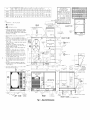
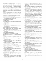
INSTALLATION
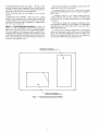
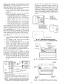
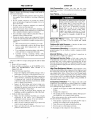
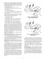
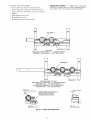
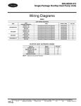
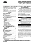
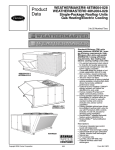
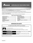
Unit is shipped in the vertical dischtuge configuration. To
convert to horizontal discharge application, remove duct opening coveLs. Using the same screws, install covers on duct openings in basepan of unit with insulation-side down. Seals around
openings must be tight. See Fig. 1.
Step 1 -- Provide
I
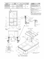
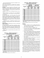
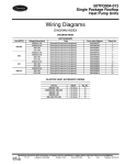
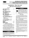
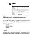
critical for a watertight seal. Install gasket supplied with the
roof curb as shown in Fig. 2. hnproperly applied gasket can
IMPORTANT: The gasketing of the unit to the roof curb is ]
result in air leaks and poor unit performance.
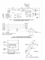
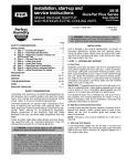
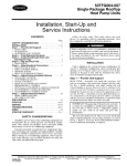
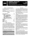
Curb should be level. Unit leveling tolerances are shown in
Fig. 3. This is necessary for unit drain to lhnction properly.
Refer to Accessory Roof Curb [nstalhttion Instructions for
additional infomtation as required.
reserves the right to discontinue, or change at any time, specifications
Catalog
Unit Support
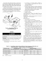
ROOF CURB -- Assemble and install accessory roof curb in
accor&mce with instructions shipped with curb. See Fig. 2. Install insulation, cant strips, roofing felt, and counter flashing as
shown. Ductwork must be attached to curb, not to the unit.
If electric control power or gas service is to be routed through
the basepan, attach the accessory thin-the-bottom
service connections to the basepan in accordance with the accessory installation instructions. Connections must be inst_dled before unit is
set on roof curb.
CONSIDERATIONS
Installation and servicing of air-conditioning equipment can
be hazardous due to system pressure and electric_d components. Only trained and qualifed service personnel should
install, repair, or service ai>conditioning equipment.
Untrained personnel can perform basic maintenance functions of cleaning coils and filters and replacing filters. All other
operations should be performed by trained service personnel.
When working on ai>conditioning equipment, observe precautions in the literature, tags and labels attached to the unit, and
other safety precautions that may apply.
Follow all safety codes. Wear safety glasses and work
gloves. Use quenching cloth for unbrazing operations. Have
fire extinguishers avaihtble for all brazing operations.
Manufacturer
Before performing service or maintenance operations on
unit, turn off main power switch to unit and install lockout
tag. Ensure electrical service to rooftop unit agrees with
voltage and amperage listed on the unit rating phtte. Electricgd shock could cause personal injury.
No. 04-53480013-01
Printed in U,S.A.
or designs without notice and without incurring obligations.
Form 48HJ-33SI
Pg 1
9-05
Replaces:
48HJ-29SI
SLAB MOUNT (Horizontal
Units Only) -- Provide a level
concrete slab that extends a minimum of 6 in. beyond unit cabinet. Install a gravel apron in front of condenser-coil air inlet to
plevent grass and foliage from obstructing airflow.
NOTE: Horizontal units may be installed on a roof curb if
required.
Ducts passing through an unconditioned
space must be insulated and covered with a vapor barriel:
If a plenum return is used on a vertical unit, the return
should be ducted through the roof deck to comply with applicable fire codes.
A minimum clearance is not required around ductwork.
Cabinet return-air static pressure (a negative condition) shall
not exceed 0.35 in. wg with economizer or 0.45 in. wg without
economizeE
ALTERNATE UNIT SUPPORT -- When the curb or adapter
cannot be used, suppoll unit with sleeper rails using unit curb
or adapter suppoll area. If sleeper rails cannot be used, suppoll
the long sides of the unit with a minimum of 3 equally spaced
4-in. x 4-in. pads on each side.
These units are designed for a minimum continuous returnair temperature in heating of 50 F (di_ bulb), or an intermittent
operation down to 45 F (di_ bulb), such as when used with a
night setback thermostat.
Step 2 --
Field Fabricate Ductwork -- Secure _fll
ducts to roof curb and building structure on veltical discharge
units. Do not connect ductwork to unit. For horizontal applications, field-supplied isolation flanges should be attached to horizont_d discharge openings and _11ductwork should be secured
to the flanges. Insulate and weatherproof all external ductwork,
joints, and roof openings with counter flashing and mastic in
accor&mce with applicable codes.
To operate at lower return-air temperatures, a field-supplied
outdoor air temperature control must be used to initiate both
stages of heat when the temperature is below 45 F. Indoor comfort may be compromised
when these lower air temperatures
are used with insufficient heating temperature rise.
REMOVABLE
HORIZONTAL
RETURN DUCT OPENING COVER '_k
k
\
\
\
\
\
\
_
REMOVABLE
HORIZONTAL
SUPPLY DUCT OPENING COVER
Fig. 1 -- Horizontal Conversion
Panels
CONNECTOR
PKG. ACCY.
B
D ALT
DRAIN
HOLE
C
CRBTMPWROO1A01
CRBTMPWROO2A01
CRBTMPWROO3A01
1'-911/16"
[551]
1'-4"
[406]
13/4',
[44.5]
CRBTMPWROO4A01
GAS
POWER
CONTROL
3/41'
[19] NPT
3/4" [19] NPT
11/4" [31.7]
1/2"NPT
[12.7]
3/4"1119]NPT
[19]3/4"NPT
11/4" [31.7]
ROOF CURB
ACCESSORY
ACCESSORY
POWER
/_
_"
/
",\
'
1
I
004-007
NOTES:
1. Roof curb accessory is shipped disassembled.
2. Insulated panels.
3. Dimensions in [ ] are in millimeters.
4. Roof curb: galvanized steel.
5. Attach ductwork to curb (flanges of duct rest
on curb).
6. Service clearance: 4 ft on each side.
7. I_
",,\
J
_ I
\\
I [610]
2'-0"
48HJ
1/2"
[12.7]
I
C
]
CRRFCURB002A01
1/21'
[12.7]
I
jl
UNIT
SIZE
CRRFCURBOOIA01
C
'_4I
A
Direction of airflow.
8. Connector
packages
CRBTMPWROO1A01
and 002A01 are for thru-the-curb
type gas.
Packages CRBTMPWROO3A01
and 004A01
are for thru-the-bottom type gas connections.
IX
I
iI
\1
i I
B
o'
3"
1753
GASKET
TYPICAL
(SUPPLIED
I
(FIELD
WITH
CURS)
O"
(4)
SIDES
7/16"
DUCT
DUPPLIED)
FLASHING
SUPPLIED)
(FIELD
I
I
O" 3"
[76]
I
I
(APPROXD
_B
I
I
I
I
2"
(FIELD
7 5/D"
[803]
5TRIP
SUPPLIED)
MATERIAL
(FIELD
5UPPL[ED)
o.
0
I
SUPPLY
I
I
1 7/16"
E341 ]
AIR
OPENING
C
"C C"
SECTION
Y
O 7116"
nl]
(DOLT HEAD5)
SCALE
-1
O"
_
O"
1"
0 7116"
[II]
(BOLT HEADD)
7[504]
13/1D3._
O'
E7B]
RIGID
(FIELD
INSULATION
DUPPLIED)
1:4
o
I
+
I
1"
..
#
I
#
#
O'
0 7/16"
3'
O"
[914]
O'
0 7/15"
OPENING
FOR
SERVICE.
HEADS)
n. _A
O'
O'
BADEPAN
(SEE
#
(BOLT
2
ENTRY
NOTE
#D)
1/2"
3 1/4"
[83]_
O"
9"
DEE NOTE
#2
#
O'
0
1/4"[73
GAD
•
(SEE
$
E
8
SUPPLY
AIR
VIEW
5ERVICE
PLATE
1'
4 13/15"
[427]
(INSIDE)
" 6"
[152]
:IND[DE)
I
I
RETURN
AIR••
"A-A"
2 3/8
°
[Bl]
I
I
HEAD OF DOLT TO BE ON
INDIDE
OF FLANGE
I
I
I
1/8"
E1705]
NOTE:
CAMBRIDGEPORT
FASTENING
ALTERNATE
Fig. 2 -- Roof Curb Details
"SURE
LOCK"
CORNER
DEVICE
IS ACCEPTABLE
CONSTRUCTION.
All panels must be in place when rigging and lifting.
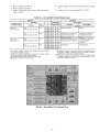
POSITIONING
-- Maintain clefuance around find above unit
to provide minimum distance from combustible materials, proper airflow, and service access. See Fig. 7.
UM ALLOWABLE
DIFFERENCE (in.)
B
OlOCl C
0.5
1.0
1.0
Fig. 3 -- Unit Leveling Tolerances
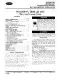
Step 3 --
Install External
Trap for Condensate
Drain
-- The unit's 3h-in. condensate drain connections am
located on the bottom and side of file unit. Unit discharge
connections do not determine the use of drain connections;
either &ain connection can be used with vertic_d or horizontal
applications.
When using the standard side &ain connection, ensure the
plug (Red) in the ;alternate bottom connection is tight before
installing the unit.
To use the bottom &ain connection for a roof curb installation, relocate the factory-inst;dled
plug (Red) from the bottom
connection to the side connection. Tile center drain plug looks
like a star connection, however it can be removed with a m/2-in.
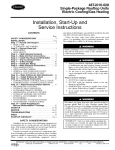
socket drive extension. See Fig. 4. The piping for the condensate &ain find external trap can be completed after the unit is in
place.
All units must have fin external trap for condensate drainage. Install a trap 4-in. deep and protect against freeze-up. If
drain line is installed downstream from the external trap, pitch
the line away from the unit fit 1 in. per 10 ft of run. Do not use a
pipe size smaller than the unit connection (3/4 in.). See Fig. 5.
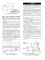
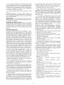
Step 4 --
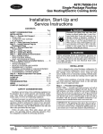
Rig and Place Unit-Inspect unit
for
transportation dmnage, and tile any claim with transpollation
agency. Keep unit upright and do not drop. Spreader bars are
not required if top crating is left on unit, and rollers may be
used to move unit across a roof. Level by using unit fl_lme as a
reference. See Table 1 and Fig. 6 for additional information.
Operating weight is shown in Table 1 and Fig. 6.
Lifting holes m'e provided in base rfdls as shown in Fig. 7.
Refer to rigging instructions on unit.
Position unit on roof curb so that file following clearances are
1/4 in. clearance
between the roof curb find the base
rail inside the front and refu'. 0.0 in. clearance between the roof
curb and the base rail inside on the duct end of the unit. This will
result in the distance between the roof curb and the base rail
inside on file condenser end of the unit being approximately
equal to Fig. 2, section C-C.
Do not install unit in an indoor location. Do not locate unit
air inlets near exhaust vents or other sources of contmninated
air
maintained:
Be sure flint unit is installed such that snow will not block
the combustion intake or flue outlet.
Unit may be installed directly on wood flooring or on
Class A, B, or C roof-covering material when roof curb is used.
Although unit is weafllerproof,
higher level runoff and overhangs.
guard against
water from
Ix>cate mechanical draft system flue assembly at least 48 in.
from an adjacent building or combustible materiffl. When unit
is located adjacent to public walkways, flue assembly must be
fit least 7 fl above grade.
NOTE: When unit is equipped with an accessory
chmge deflector, allowable clearance is 18 inches.
Flue gas can deteriorate building materials.
that flue gas will not affect building materials.
flue dis-
Orient unit such
Adequate combustion-air space must be provided for proper
operation of this equipment. Be sure that installation complies
with all local codes and Section 5.3, Air for Combustion find
Ventilation, NFGC (National Fuel Gas Code), ANSI (American National Standards Institute) Z223.1-1984 find addendum
Z223.1a-1987.
In Canada, installation must be in accordance
with the CANI.BI49.1
and CANI.BI49.2
installation codes
for gas burning appliances.
Flue vent dischmge must have a minimum horizontal clearance of 4 fl from electric and gas meters, gas regulators, find
gas relief equipment.
After unit is in position, remove shipping materials
ging skids.
\
OPEN
I
IIII
/ I I
IIII
2" MINI
VENT
and rig-
SEE
NOTE
_L_
HORIZONTAL
DRAIN OUTLET
NOTE: Drain plug is shown in factory-installed position.
Fig. 4-
.,,_ROOF
CURB
DRAIN PLUG
Condensate
Drain Pan
NOTE: Trap should be deep enough to offset maximum unit static
difference. A 4-in. trap is recommended.
Fig. 5 -- Condensate
Drain Piping
Details
36"- 54"
(914-1371)
POSITION ALL SEAL STRIPS
IN PLACE BEFORE POSITIONING
UNIT ON ROOF CURB,
DETAIL
"A"
DUCT END
SEE "A_DETAIL
PLACE UNIT ON CURB AS CLOSE
TO DUCT END AS POSSIBLE
NOTES:
1. Place unit on curb as close as possible to the duct end.
2. Dimension in ( ) is in millimeters.
3. Hook rigging shackles through holes in base rail as shown in
detail "A." Holes in base rails are centered around the unit
center of gravity. Use wooden top skid when rigging to prevent
rigging straps from damaging unit.
4. Weights include base unit without economizer. See Table 1 for
unit operating weights with accessory economizer.
6. Weights include base unit without the Humidi-MiZer TM adaptive
dehumidification system. See Table 1 for unit operating weights
with the Humidi-MiZer system.
All panels must be in place when rigging.
UNIT
48HJ
OPERATING
WEIGHT
004
Ib
530
kg
240
005
540
245
006
560
254
007
635
288
"A"
in.
73.69
73.69
73.69
73.69
"g"
mm
1872
1872
1872
1872
in.
35.50
35.50
35.50
35.50
"C"
mm
902
902
902
902
in.
33.31
33.31
33.31
33.31
mm
847
847
847
847
Fig. 6 -- Rigging Details
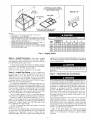
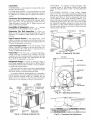
Step 5 --
Install Flue Hood -- Flue hood is shipped
screwed to the burner comp;utment
access panel. Remove
from shipping location and, using screws provided, inst;dl flue
hood in location shown in Fig. 7 and 8.
For units being installed in California Air Quality Management Districts which require NOx emissions of 40 nanogrmns/
joule or less, a low NOx unit must be installed.
NOTE: Low NOx units are available for 3 to 5 ton units.
Install Gas Piping -- Unit is equipped for
use with type of gas shown on nameplate.
Refer to local
building
codes, or in the absence
of local codes, to
ANSI Z223.1-1984
and addendum
Z223. IA- 1987 entitled
National Fuel Gas Code. In Canada, installation must be in
accordance with the CANI .B149.1 and CANI .B149.2 installation codes for gas burning appliances.
For natural gas applications, gas pressure at unit gas connection must not be less than 4 in. wg or greater than 13 in. wg
while the unit is operating. On 48HJ005-007
high-heat units,
the gas pressure at unit gas connection must not be less than
5 in. wg or greater than 13 in. wg while the unit is operating.
For propane applications, the gas pressure must not be less than
5 in. wg or greater than 13 in. wg at the unit connection.
Size gas supply piping for 0.5 in. wg maximum pressure
drop. Do not use supply pipe sm_dler than unit gas connection.
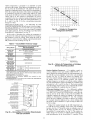
Support gas piping as shown in the table in Fig. 9. For example, a 3/4-in. gas pipe must have one field-fabricated
support
bemn every 8 ft. Therefore, an 18-ft long gas pipe would have a
minimum of 3 support beams, and a 48-ft long pipe would
have a minimum of 6 support beams.
See Fig. 9 for typical pipe guide and locations of extermd
manual gas shutoff valve.
piping can be routed through field-drilled holes in the basepan.
The basepan is speci_dly designed and dimpled for drilling the
access connection holes.
When connecting the gas line to the unit gas v_dve, the
installer MUST use a backup wrench to prevent damage to
the v_dve.
Step 6 --
NOTE: If accessory thin-the-bottom
connections and roof curb
are used, refer to the Thin-the-Bottom
Accessory Installation
Instructions
for information
on power
wiring and gas
connection piping. The power wiring, control wiring and gas
Step 7 -- Make Electrical
Connections
Unit cabinet must have an unintenupted,
unbroken electric_d ground to minimize the possibility of pel.sonal injury if
an electrical fault should occm: This ground may consist of
electric_d wire connected to unit ground lug in control compartment, or conduit approved for electrical ground when
installed in accordance
with NEC (Natiomd Electrical
Code), ANSI/NFPA
(National Fire Protection Association), latest edition, and local electrical codes. Do not use
gas piping as an electrical ground Failure to follow this
warning could result in the installer being liable for personal injury of others.
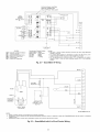
FIELD POWER SUPPLY -- All units except
208/230-v
units are factory wired for the voltage shown on the nameplate.
If the 208/230-v unit is to be connected to a 208-v power supply, the transformer must be rewired by moving the black wire
from the 230-v terminal on the transformer and connecting it to
the 200-v terminal from the transformel:
Refer to unit label diagram for additional
information.
Pigtails me provided for field service. Use factory-supplied
splices or UL (Underwriters'
Laboratories) approved copper
connectoE
STD. UNIT
WEIGHT
LB
KG
UNIT
530
240
4BHJ_OO5
540
560
4BHJ_O07
G35
48HJ_004
!CONOMI_ERI_ VERT. ECONIV
(A)
(SI
(C)
(D)
WEIGHT
W/P.E. WEIGHT CORNER WEIGHT CORNER WEIGHT CORNER WEIGHT CORNER WEIGHT
LB
KG
LB
KG
LB
KG
LB
KG
LB
KG
LB
KG
50
22,7
go
40,S
127
57,G
122
55,3
138
62.8
143
84,9
245
254
129
134
SS.5
60.8
124
129
55.2
58.5
141
148
54.0
66.2
145
151
55.2
88.5
288
152
68.S
147
55.7
1S5
74.8
171
77.5
2"
iN.
MM
S 5/16"
84G.5
4BHJ_OO5
;
3"
;
5 5/15"
CONNECTION
BOTTOM POWER CHART:
THE5E HOLE5 REG'D FOR U5E
WITH ACCE550RY
PACKAGES
CRBTMPWROO1A01,
2A01,
3A01,
OR 4A01
"J"
FT
1050
THREADED
CONDUIT 5]ZE
WIRE
USE
1/2"
1/2"
3/4"
(001,003)
1/4"
(O02,004)
(003)
1/2"FPT
ACC.
24V
DOWER_
DOWER_
GA5
1
2"
3/8"
SIZES
DIA.
DIA.
[3B]
[51]
FIELD
POWER
POWER
SUPPLY
SUPPLY
KNOCK
HOLE
OUT
REQ'D HOLE
SIZES
(MAX.)
7/8"[22.2]
7/B'[22.2]
1 1/8"[28.4]
1 3/4"[44,4]
1 1/4"[31.8]
NOTES=
1.
DIMENSIONS
2.
_CENTER
IN
[
]
ARE
IN
MILLIMETERS.
3.
_
4.
ON VERTICAL
DISCHARGE
UNITS,
DUCTWORK TO BE ATTACHED
TO ACCESSORY
ROOF CURB ONLY.
FOR HORIZONTAL
DISCHARGE
UNITS
FIELD
SUPPLIED
FLANGES
SHOULD
BE ATTACHED
TO
HORIZONTAL
DISCHARGE
OPENINGS,
AND ALL DUCTWORK
SHOULD
BE ATTACHED
TO THE FLANGES.
CORNER
MINIMUM
CLEARANCE
(LOCAL
CODES OR JURISDICTION
MAY
PREVAIL):
BETWEEN
UNIT,
FLUE
SIDE
AND COMBUSTIBLE
SURFACES,
35 IN.,18
IN.
WHEN USING
ACCESSORY
FLUE
DISCHARGE
DEFLTR.
BOTTOM OF UNIT
TO COMBUSTIBLE
SURFACES
(WHEN NOT USING
CURB)
1 INCH.
BOTTOM OF BASE
RAiL
TO COMBUSTIBLE
SURFACES
(WHEN NOT
USING
CURB)
O INCHES.
CONDENSER
COIL,
FOR PROPER
AiR
FLOW,
3B iNCHES
ONE SIDE,
12 iNCHES
THE OTHER.
THE SIDE
GETTING
THE
GREATER
CLEARANCE
IS OPTIONAL.
OVERHEAD,
SO iNCHES
TO ASSURE PROPER
CONDENSER
FAN
OPERATION.
3"
REAR
OF GRAVITY.
(DISPOSABLE
S.
a.
b.
c.
d.
DIRECTION
OF
AIR
F [ LTER/ECONOM
FLOW.
e.
F.
BETWEEN
UNITS,
CONTROL
BOX SIDE,
42 IN.
PER NEC.
BETWEEN
UNIT
AND UNGROUNDED
SURFACES,
CONTROL
BOX
SIDE,
38 IN.
PER NEC.
g.
BETWEEN
UNIT
AND BLOCK
OR CONCRETE
WALLS AND OTHER
GROUNDED SURFACES,
CONTROL
BOX SIDE,
42 IN.
PER NEC.
HORIZONTAL
SUPPLY
AND RETURN
END,
0 INCHES
WHEN THE
ALTERNATE
CONDENSATE
DRAIN
IS USED.
h.
B.
WITH THE EXCEPTION
COIL
AND COMBUSTION
AND c,
A REMOVABLE
CLEARANCE.
7.
UNITS
MAY BE INSTALLED
FROM WOOD OR CLASS A,
IF SET ON BASE
RAIL.
8.
[ ZER
ICONDENSER
_L
(BO_#"
_4_f
4
9
UP
71"7
_O'
c ft
COIL
RETURN
AIR
ALTI
OPENING
O'
I0 1S/1B"
[278]
I
SUPPLY
1S/1B"
[4S]
O" 3 SW1B"
[99.4]
_
AIR
l
I
2"11
O"
[BOB]
3" O"
[gl 4]
G"
3 13/1B"
[97]
FLUE HOOD
3
O"
SUPPLY
AIR
_
S 7/1B"
1"
O'
7 1/4"
_[1B4]
O" lO 13/15"
l'
1 11/1G"
[1872]
O'
S SW1B"
[439.7]
//
O"
0 7/IS'Ell.l]
L
_ ECONOM[$ER
O'
IV
4 1/1B"
W/
POWER
EXHAUST
O 3/8"
h
FAN MOTOR
ACCESS
PANEL
x
3 5/IB"
Egl.O]
1"
2 7/8"
[375.B]
SUPPLY
AIR
HOR[
h
Nh
ZONTAL
h
Nil
7"
h
III HORIZONTAL
II
h
IlL
Ill
h
2"
1 ll/1G"
[852.5]
l'
OUTSIDE
O"
OPENING
_®1
8
1/4"
AIR
0
7/8"
j
5 3/8
[74B. 2]
_0'
S
ll/1B"
[144.3]
"FORK
TRUCK
SLOTSo, 2 1/4"DIA
O'
5 [14B]3/4"
OUT_J_L'y[BSB'B]lAIR15/1B"
RETURN
BISGONNEGTLooATION
[Sl4]
h
O" [2141B
7/1B
SIDE
1/4"
,£4
"C"
lli
2"
S
//4/`
_[81]
4 5/16"
[414.5]
[104B]
[470]
1 'G 1/2"_
[13B]
1/16"
[78]_
O' B S/B"
[168.23
EG5_
LEFT
_
CONTROL
BOX/COMPRESSOR/
BURNER ACCESS
PANEL
_0"
TYP
8/1 G"
AIR
_°'2Ss_G'EBs
III
IllS.B]
RETURN
3/8"
L__IJ
INDOOR
SLOWER
l"
S
[137]
1'53/4"[451]
FRONT
FACTORY
SIDE
_.____j
O"
CONDENSATE
, DRAIN
OPENING
IN SASEPAN
FROM
RIGHT
S3Zl@"
' E/' I----i
9"
[1144]
O'
r---1
[81]
EVAPORATOR
I
I
VERTIGAL
I,
CORNER
G'[457]
DO
VIEW 5 5
ON COMBUSTIBLE
FLOORS
MADE
S,
OR C ROOF COVERING
MATERIAL
1'
BLOCKOFF
PANEL
1" S 1/4"
[438]
FOR ECONOM]$ER [V
PANEL_
OF THE CLEARANCE
FOR THE CONDENSER
SIDE
AS STATED
IN NOTE #Sa,
b,
FENCE
OR BARRICADE
REQUIRES
NO
THE VERTICAL
CENTER
OF GRAVITY
IS
FROM THE BOTTOM OF THE BASE
RAIL.
FILTERS)
ACCESS
[573
FRONT
(TYP
s PLACES)
Fig. 7 -- Base Unit Dimensions
OF
AIR
BAROMETRIC
PANEL
R IGHT
S IDE
E STD.
CONDENSATE
DRAIN
RELIEF
DISCHARGE
[5143
When installing
All field
requirements.
\
Fig. 8--
i=
FLUE OPENING
Flue Hood Details
9" MINIMUM
must
comply
with
per NEC.
NEC
and
local
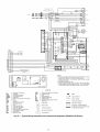
Install conduit through side panel openings indicated in
Fig. 7. Route power lines through connector to terminal connections as shown in Fig. 10.
k -41
INTAKE LOUVERS
units, provide a disconnect
wiring
X
CLEARANCE
Voltage to compressor terminals during operation must be
within voltage range indicated on unit nmneplate (also see
Tables 2A-2D). On 3-phase units, voltages between phases
must be balanced within 2% and the current within 10%. Use
the formula shown in Tables 2A-2D, Note 3 to determine the
percent voltage imbalance. Operation on improper line voltage
or excessive phase imbalance constitutes abuse and may cause
&image to electric_d components. Such operation would inv_di&_te any applicable Carrier warranty.
NOTE: If accessory thin-the-bottom
connections and roof curb
tu'e used, refer to the Thru-the-Bottom
Accessory Installation
Instructions for information on power wiring and gas connection piping. The power wiring, control wiring and gas piping
can be routed through field-drilled holes in the baseptm. The
basepan is specially designed and dimpled for drilling the
access connection holes. See Fig. 2.
FIELD CONTROL WIRING -- Install a Carrier-approved
accessory thermostat assembly according to inst_dlation instructions included with the accessory. Ix)cate thermostat
assembly on a solid wail in the conditioned space to sense average temperature
in accor&mce with thermostat
installation
instructions.
4
FROM GAS METER
SUPPORT*
LEGEND
NFGC -- National Fuel Gas Code
Connect
low-voltage
*Field supplied,
NOTE: Follow all local codes.
SPACING OF SUPPORTS
STEEL PIPE
NOMINAL DIAMETER
1/2
a/4or I
1V4 or larger
(in.)
Route thermostat cable or equivalent single leads of colored
wire from subbase termin_ds through connector on unit to lowvoltage connections (shown in Fig. 11A and 11B).
SPACING OF SUPPORTS
X DIMENSION (ft)
6
8
10
Fig. 9 -- Gas Piping Guide (With Accessory
Thru-the-Curb Service Connections)
thermostat wires to matching screw termimds
connection bozud. See Fig. 11A and I lB.
of
NOTE: For wire runs up to 50 fl, use no. 18 AWG (American
Wire Gage) insulated wire (35 C minimum). For 50 to 75 It,
use no. 16 AWG insulated wire (35 C minimum). For over
75 ft, use no. 14 AWG insulated wire (35 C minimum). All
wire larger than no. 18 AWG cannot be directly connected to
the thermostat and will require a junction box and splice at the
thermostat.
Pass the control wires through the hole provided in
corner post; then feed wires through the raceway built into
corner post to the 24-v barrier located on the left side of
control box. See Fig. 12. The raceway provides the UL
quired cle_u'ance between high and low-voltage wiring.
the
the
the
re-
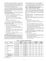
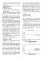
HEAT ANTICIPATOR SETTINGS -- Set heat anticipator settings at 0.14 amp for first stage and 0.14 for second stage heating, when available.
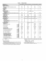
Table 1 -- Physical Data
BASE UNIT 48
NOMINAL CAPACITY
HJE/F/H/K]M/NO04
3
OPERATING WEIGHT (Ib)
Unit
Humidi-MiZer
TM Adaptive
EconoMi$er IV
Roof Curb
Dehumidification
530
15
50
115
System
COMPRESSOR
ouontity
1
Oil (oz)
REFRIGERANT TYPE
Expansion Device
Operating Charge (Ib-oz)
Standard
Unit With Unit
Humidi-Mizer
CONDENSER
42
Adaptive
Dehumidification
5-8
12-5
System
3500
V4 ,825
180
Scroll
1
53
TM
I
R-22
Metering
10-2
16-8
635
29
50
115
1
I 1
50
60
Device
I
10-0
20-5
I
4100
V4_1100
320
Enhanced Copper Tubes, Aluminum
1_,17
146
Motor Bearing Type
Maximum Fan Rpm
Motor Pulley Pitch Diameter
Dehumidification
12-8
23-14
Fan Pulley Pitch Diameter
Belt -- Type,.,Length
(in,)
(in,)
(in.)
Pulley Center Line Distance (in.)
Speed Change per Full Turn of
Movable Pulley Flange (rpm)
Movable Pulley Maximum Full
Turns from Closed Position
Factory Setting -- Full Turns Open
Speed Setting
2_.17
165
I
(rpm)
4100
V4_1100
320
Lanced Fins
2_,17
165
Double-Wavy
I
2.17
21 3
Fins
2._15
5,5
2_15
5.5
4_15
5.5
4_,15
73
1_,17
3,9
2...17
3.9
2_.17
3.9
2_17
5.2
System
Std
Hi-Static
Std
Hi-Static
Std
Hi-Static
A/B (in.)
Motor Shaft Diameter
I
Enhanced Copper Tubes, Aluminum
Fan Rpm Range
Fan Shaft Diameter
560
25
50
115
3500
V4 ..825
180
COIL
Motor Frame Size
Std
Hi-Static
Std
Hi-Static
Std
Hi-Static
Std
Hi-Static
Std
Hi-Static
Std
Hi-Static
Std
Hi-Static
Std
Hi-Static
1...10 x 10
1200
1.20
2.40
48
56
680-1044
1075-1455
Ball
2100
1.9/2.9
2.8/3.8
l&
%
4.5
4.5
1 ...A...36
1 _.A_.39
10.0-12.4
65
65
5
6
3
at Pulley (in.)
LEGEND
Bhp--
I
HJD/E/FO07
6
Propeller
EVAPORATOR COIL
Standard Unit
Rows.,,Finslin,
Total Face Area (sq ft)
Unit with Humidi-Mizer
Adaptive
Rows,..Finslin,
Total Face Area (sq ft)
EVAPORATOR FAN
°uantity..,Size
(in.)
Nominal Cfm
Maximum Continuous
Bhp
Factory
I
FAN
Rows...Fins/in,
Total
Face Area (sq ft)
Nominal
HJD/E/F/G/H/K]L/M/NO06
5
540
23
50
115
Acutrol
Nominal Cfm
Motor Hp...Rpm
Watts Input (Total)
CONDENSER
HJD/E/F/G/H/K]L/M/NO05
4
Brake Horsepower
*Single phase/three phase,
tlndicates automatic reset,
**60,000 and 72,000 Btuh heat input units have 2 burners, 90,000 and
120,000 Btuh heat input units have 3 burners. 115,000 Btuh heat input units
and 150,000 Btuh Heat input units have 3 burners.
l-tAn LP kit is available as an accessory. Kit may be used at elevations as high
as 2000 ft, If an LP kit is used with Low NOx units, the Low N©x baffle must
be removed and the units will no longer be classified as Low N©x units.
31/2
826
1233
%
Centrifugal Type, Belt Drive
1...10 x 10
1,.,10 x 10
1600
2000
1.20
1.30/2.40"
2,40
2,90
48
48/56"
56
56
770-1185
1035-1460
1075-1455
1300-1685
Ball
Ball
2100
2100
1.9/2.0
2.4/3.4
2.8/3.8
3.4/4,4
1/2
%
5/s
5/8
4.0
4.0
4.0
4.5
1..,A.,.36
1 ..-4-.40
1,_A_.39
1,..A-.40
10.0-12.4
14.7-15.5
7O
75
65
6O
5
6
6
5
3
3
31/2
31/2
936
1248
1233
1396
5/s
5/8
1..,10 x 10
2400
2,40
2,90
56
56
1119-1585
1300-1685
Ball
2100
2,4/3,4
3,4/3,4
5/8
7&
4.0
4.5
1 ..,A,..38
1..,A_.40
14.7-15.5
95
60
5
5
3
1305
1396
5/8
IIThree-phase standard models have heating inputs as shown, Singlephase standard models have one-stage heating with heating input values
as follows:
HJD005-006,HJE004
-- 72,000 Btuh
HJE005-006,HJF004
-- 115,000 Btuh
HJF005-006 -- 150,000 Btuh
***California compliant three-phase models.
tttCalifornia
SCAQMD compliant low NO× models have combustion products
that are controlled to 40 nanograms per joule or less,
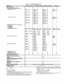
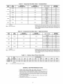
Table 1 -- Physical Data (cont)
BASE UNIT 48
HJE/F/H/K]M/N004
FURNACE SECTION
Rollout Switch Cutout Temp (F)t
Burner Orifice Diameter (in, ..,drill size)**
Natural Gas -- Std
Liquid Propane -- Alttt
Thermostat Heat Anticipator
208/230/460/575 v
First Stage
Second Stage
Gas Input (Btuh)
First Stage/Second Stage
Efficiency
Rise Range
Manifold Pressure (in. wg)
Natural Gas -- Std
Liquid Propane -- Alttt
Maximum Static Pressure (in, wg)
Field Gas Connection Size (in.)
195
195
HJD.113...33
HJE .113...33
HJF.129-.30
HJD.113.-33
HJE .113.-33
HJF.129-.30
HJH,113-.33
HJK,113-.33
HJG .113...33
HJH.113...33
HJK.129...30
HJG .113...33
HJH .113...33
HJK.129.-30
HJM .102,,.38
HJN.102-.38
HJL.102...38
HJM ,102,..38
HJN.116...32
HJL.102.-38
HJM .102...38
HJN.116-.32
HJE,089.,.43
HJF,089..,43
HJD.089...43
HJE .089...43
HJF.104...37
HJD.089.-43
HJE .089...43
HJF.104...37
HJH,089.,.43
HJK,089-.43
HJG .089...45
HJH .089...45
HJK.102...38
HJG .089...43
HJH .089...43
HJK.104.-37
HJM
HJN
HJL.082-.45
HJM .082.,.45
HJN.094...42
HJL.082-.45
HJM.082...45
HJN .094.,.42
.082,.,45
,082,,.45
HJD/E/F007
195
HJE.113...33
HJF,113..,33
,14
.14
.14
.14
195
HJD,113-,33
HJE ,113-.33
HJF,129.-30
HJD .089_.43
HJE ,089-.43
HJF.104.-37
.14
.14
HJEll50,000/
72,000
HJFI182,000/115,000
HJDll 50,000/ 72,000
HJEII 82,000/115,000
HJFl1120,000/150,000
HJDII 50,000/ 72,000
HJEII 82,000/115,000
HJFI1120,000/150,000
HJH***--/
72,000
HJK***--/115,000
HJG***--/
72,000
HJH*** --/115,000
HJK*** --/150,000
HJG***--/
72,000
HJH*** --/115,000
HJK*** --/150,000
HJMTTT--/
HJNttt--/
HJLttt
--/ 60,000
HJMttt--/
90,000
HJNttt
--/120,000
HJD 82.8
HJE 81
HJF 80.4
HJLttt--/ 60,000
HJMftt--/
90,000
HJNttt
--/120,000
HJD 82.8
HJE 81
HJF 80.4
HJH 82
HJK 80
HJG 82
HJH 81
HJK 80
HJG 82
HJH 81
HJK 80
HJM 80.2
HJN 81
HJL 80.2
HJM 81
HJN 80.7
HJL 80.2
HJM 81
HJN 80.7
HJE 25-55
HJF 55-85
HJD 25-25
HJE 35-65
HJF 50-80
HJD 25-55
HJE 35-65
HJF 50-80
HJH 25-55
HJK 55-85
HJG 25-55
HJH 35-85
HJK 50-80
HJG 25-55
HJH 35-65
HJK 50-80
HJM 20-50
HJN 30-60
HJL 20-50
HJM 30-60
HJN 40-70
RJL 20-50
HJM 30-60
HJN 40-70
60,000
90,000
HJE 82,8
HJF80
3.5
3.5
1.0
3.5
3.5
1.0
RETURN-AIR FILTERS
Quantity...Size (in.)
LEGEND
Brake Horsepower
*Single phase/three phase.
tlndicates automatic reset.
**60,000 and 72,000 Btuh heat input units have 2 burners. 90,000 and
120,000 Btuh heat input units have 3 burners. 115,000 Btuh heat input units
and 150,000 Btuh Heat input units have 3 burners.
ttAn LP kit is available as an accessory. Kit may be used at elevations as high
as 2000 ft. If an LP kit is used with Low NOx units, the Low NOx baffle must
be removed and the units will no longer be classified as Low N©x units.
.14
.14
HJD 50,000/ 72,000
HJE 82,000/115,000
HJF 120,000/150,000
HJD 82
HJE 81
HJF 80
HJD 25-55
HJE 35-65
HJF 50-80
3.5
3.5
1.0
l&
1/2
HIGH-PRESSURE
SWITCH (psig)
Standard Compressor
Internal Relief
Cutout
Reset (Auto.)
LOSS-OF-CHARGE
SWITCH/LOW=PRESSURE
SWITCH (Liquid Line) (psig)
Cutout
Reset (Auto.)
FREEZE PROTECTION THERMOSTAT
Opens (F)
Closes (F)
OUTDOOR-AIR
INLET SCREENS
Bhp--
HJD/EIF/GIH/K/LIM/NO06
Setting (amps)
(Steady State) (%)
Temperature
HJD/E/FIGIHIK/L/M/NO05
3.5
3.5
1.0
1/2
450 _+50
428
32O
7_+3
22 _+5
30_+5
45_+5
Cleanable.
Screen quantity and size varies with option selected.
Throwaway
2._16x25x2
I
4_.16x
16x2
IIThree-phase
standard models have heating inputs as shown. Singlephase standard models have one-stage heating with heating input values
as follows:
HJD005-006,HJE004
-- 72,000 Btuh
HJE005-006,HJF004115,000 Btuh
HJF005-006150,000 Btuh
***California compliant three-phase models.
tttCalifornia
SCAQMD compliant low NOx models have combustion products
that are controlled to 40 nanegrams per joule or less.
BLK _
BLK
TO COMP
BLK _
TO COMP
I
,,
1
YEL
I;%F'i'
[;%
EQUIP
GND
F--t_I
i
1
PI ELD POWER SUPPLY
_ .L .L L __
FDISOON.EDT
7
PER NEC
208/230-1-60
L* ....
(SIZES 48HJ004-006)
BLK
i
_
I
ii
J
TO COMP
'
,
575-3-60
(SIZES 48HJ004,
FIELD POWERSUPPLY
_ .L.L .L -208/230-3-60460-3-60 _F-DISCONNEcT 7
(SIZES 48HJ004, 005)
L.. PERNEC ,{
BLK ---_J
!
I
TO
I
TB2
I®®1
LEGEND
1
I
575-3-50
(SIZES48HJ006,
FIELD POWER SUPPLY
_ ,.L_ .L -,r-D ISCONNECT 7
208/230-3-50
460-3-80
(SIZES 48HJ006,
007)
FIELD POWER SUPPLY
_I.LL__
[-DI SCONNECT 7
L
PE?NEC
j
L ZE._"_"EC_
:
007)
005)
I
I
I
FIELD POWERSUPPLY
r -- a-.L L--7
_ DISCONNECT I
L .....PER NEC J
C
COMP
EQUIP
GND
IFC
------
NEC
TB
---
Contactor
Compressor
Equipment
Ground
Indoor (Evaporator)
Fan Contactor
National Electrical Code
Terminal Block
Fig. 10 -- Power Wiring Connections
m
COOL STAGE
1
CONTROL
R
FAN
THERMOSTAT
CONNECTION
BOARD
G
CONTROL
CONNECTION
BOARD
Y1
HEAT STAGE
1
COOL STAGE
2
Y/Y2
HEAT STAGE
2
O/W2
24 VAC HOT
-
•
]
f-
-
I
F__J
Y2
W1
WIRE
CONNECTIONS
TO
LOW-VOLTAGE
SECTION
{_
RMTOCC
T_i
CMPSAFE1
!_
*_1_'-
_YY11/_
{£_i '_
{:_)
/'W2_
(W2}
W2
R
(Wl_,
SFS
4
NOT USED
i
,
=
C
24 VAC COM
IPD/X
\
/
7 G \
\
/
N/A
OUTDOOR
AIR
( %?x
$1
SENSOR
Fig. 11 B -- Low Voltage Connections
(Units with PremierLink TM Controls)
$2
4
THERMOSTAT
DIPSWITCH
{:::_}
SETTINGS
ON
A
B
C
D
RACEWAY
LEGEND
LOW VOLTAGE
INTEGRATED
CONNECTIONS
CONTROLLER
GAS UNIT
(IGC)
Field Wiring
NOTE: Underlined letter indicates active thermostat
configured for A/C operation.
output when
Fig. 11A -- Low-Voltage Connections With or
Without Economizer or Two-Position Damper
HOLE
IN END
Fig. 1210
PANEL (HIDDEN)
Field Control
Wiring Raceway
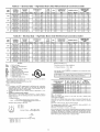
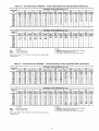
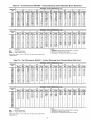
Table 2A -- Electrical Data -- Standard Motor Units Without Electrical Convenience Outlet
UNIT
48HJ
NOMINAL VOLTAGE
(V-Ph-Hz)
208/230-1-60
208/230-3-60
460-3-60
575-3-60
208/230-1-60
208/230-3-60
460-3-60
575-3-60
208/230-1-60
208/230-3-60
460-3-60
575-3-60
208/230-3-60
460-3-60
575-3-60
OO4
(3 Tons)
005
(4 Tons)
006
(5 Tons)
0O7
(6 Tons)
VOLTAGE
RANGE
Min
Max
187
254
187
254
414
508
518
632
187
284
187
254
414
508
518
632
187
254
187
284
414
508
518
632
187
254
414
508
518
632
COMPRESSOR
(each)
Qty
RLA
LRA
16.0
88.0
10.3
77.0
1
8.1
39.0
4.2
31.0
23.7
126.0
13.5
93.0
1
6.4
46.5
6.4
40.0
28.8
169.0
17.3
123.0
1
9.0
62.0
7.1
50.0
20.5
186.0
1
9.6
75.0
7.7
56.0
OFM
(each)
FLA
0.7
0.7
0.4
0.4
0.7
0.7
0.4
0.4
1.5
1.5
0.8
0.8
1.4
0.6
0.6
IFM
FLA
4.9
4.9
2.2
2.2
4.9
4.9
2.2
2.2
8.8
5.8
2.6
2.6
5.8
2.6
2.6
COMBUSTION
FAN MOTOR
FLA
.60
.60
.30
.30
.60
.60
.30
.30
.60
.60
.30
.30
.60
.30
.30
POWER SUPPLY*
MCA
25.6/25.6
18.5/18.5
9.0
7.3
35.2/35.2
22.5/22.8
10.6
10.1
46.3/46.3
28.9/28.9
14.7
11.6
32.8/32.8
15.2
12.2
MINIMUM UNIT
DISCONNECT SIZEt
FLA
LRA
25/25
101/101
18/18
90/90
9
46
7
37
34/34
139/139
22/22
106/106
10
54
10
46
45/45
216/216
28/28
168/168
14
84
12
68
32/32
200/200
15
97
12
74
MOCP**
30/30
25/25
20
20
45/45
30/30
20
20
60/60
38/35
20
20
40/40
20
20
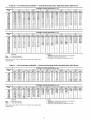
Table 2B -- Electrical Data -- Standard Motor Units With Electrical Convenience Outlet
UNIT
48HJ
NOMINAL VOLTAGE
(V-Ph-Hz)
208/230-1-60
208/230-3-60
460-3-60
575-3-60
208/230-1-60
208/230-3-60
460-3-60
575-3-60
208/230-1-60
208/230-3-60
460-3-60
575-3-60
208/230-3-60
460-3-60
575-3-60
004
(3 Tons)
005
(4 Tons)
006
(5 Tons)
007
(6 Tons)
VOLTAGE
RANGE
Min
Max
187
254
187
254
414
508
818
632
187
284
187
254
414
508
518
632
187
284
187
254
414
508
518
632
187
284
414
508
518
632
COMPRESSOR
(each)
Qty
RLA
LRA
16.0
88.0
10.3
77.0
1
5.1
39.0
4.2
31.0
23.7
126.0
13.5
93.0
1
6.4
46.5
6.4
40.0
28.8
169.0
17.3
123.0
1
9.0
62.0
7.1
50.0
20.5
156.0
1
9.6
75.0
7.7
56.0
OFM
(each)
FLA
0.7
0.7
0.4
0.4
0.7
0.7
0.4
0.4
1.5
1.5
0.8
0.8
1.4
0.6
0.6
IFM
FLA
4.9
4.9
2.2
2.2
4.9
4.9
2.2
2.2
8.8
5.8
2.6
2.6
8.8
2.6
2.6
LEGEND
FLA
HACR
---
IFM
LRA
MCA
MOCP
NEC
OFM
RLA
UL
---------
*The
right
tUsed
**Fuse
COMBUSTION
FAN MOTOR
FLA
.60
.60
.30
.30
.60
.60
.30
.30
.60
.60
.30
.30
.60
.30
.30
Determine maximum
(AB) 457 - 482 =
(BC) 464 - 487 =
(AC) 487 -488 =
Maximum deviation
Full Load Amps
Heating, Air Conditioning and
Refrigeration
Indoor (Evaporator) Fan Motor
Locked Rotor Amps
Minimum Circuit Amps
Maximum Overcurrent Protection
National Electrical Code
Outdoor (Condenser) Fan Motor
Rated Load Amps
Underwriters' Laboratories
Determine
= 1.83%
This amount of phase imbalance
mum allowable 2%.
I
_)
as it is below the maxi-
2%,
contact your
local
electric
utility phase
company
immediately.
MPORTANT:
If the
supply
voltage
imbalance
is more than
POWER EXHAUST
PART NO.
CRPWREXH021A01
CRPWREXH022A01
CRPWREXH023A01
CRPWREXH028A01
CRPWREXH029A01
CRPWREXH030A01
N/A --
max voltage deviation from average voltage
average voltage
EXHAUST
ELECTRICAL
DATA
MCA
MCA
MCA
(230 v)
N/A
3.3
N/A
1.7
N/A
1.6
(460 v)
0.9
N/A
1.8
N/A
1.0
N/A
(575 v)
N/A
1.32
N/A
0.68
N/A
0.64
MOCP
(for separate
power source)
15
15
15
15
15
15
Not available
NOTE: If a single power source is to be used, size wire to include power
exhaust MCA and M©CR
Example: Supply voltage is 460-3-60.
C
is satisfactory
See table at
NOTES:
1. In compliance with NEC requirements for multimotor and combination
load equipment (refer to NEC Articles 430 and 440), the overcurrent
protective device for the unit shall be fuse or HACR breaker. The UL,
Canada units may be fuse or circuit breaker.
2. Electrical data based on 95 F ambient outdoor-air temperature _+10%
voltage.
3, Unbalanced 3-Phase Supply Voltage
Never operate a motor where pbase imbalance in supply voltage is
greater than 2%. Use the following formula to determine the pereent
voltage imbalance.
% Voltage Imbalance
B
deviation from average voltage.
5v
7 v
2 v
is 7 v.
percent of voltage imbalance.
7
= 100x
POWER
A
MINIMUM UNIT
DISCONNECT SIZEt
FLA
LRA
30/30
106/106
24/24
98/98
11
48
9
38
39/39
144/144
27/27
111/111
13
56
12
47
50/50
221/221
34/34
173/173
17
87
13
70
37/37
205/205
17
99
14
75
% Voltage Imbalance
values listed in this table do not include power exhaust.
for power exhaust requirements.
to determine minimum disconnect per NEC.
or HACR circuit breaker.
= 100 x
POWER SUPPLY
WITH OUTLET*
MCA
MOCP**
31.6/31.6
38/38
24.5/24.5
30/30
11.7
20
9.5
20
41.2/41.2
50/80
28.8/28.5
35/35
13.3
20
12.2
20
52.3/52.3
60/60
34.9/34.9
40/40
17.4
20
13.8
20
38.8/38.8
45/45
17.9
20
14.3
20
Check MCA and MOCP when power exhaust is powered through the unit.
Determine the new MCA including the power exhaust using the following
formula:
AB = 452 V
BC = 464 v
Average Voltage =
AC = 455 v
MCA New = MCA unit only + MCA of Power Exhaust
For example, using a 48HJD006---5
unit with MCA = 28.9 and MOCP = 35.
with CRPWREXH030A01
power exhaust.
MCA New = 28.9 amps + 1.6 amps = 30.5 amps
If the new MCA does not exceed the published MOCE then M©CP would net
change. The MOCP in this example is 35 amps and the MCA New is below
35; therefore the MOCP is acceptable. If "MCA New" is larger than the published MOCE raise the MOCP to the next larger size. For separate power, the
MOCP for the power exhaust will be 15 amps per NEC.
452 + 464 + 455
3
1371
3
= 457
))
II
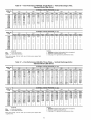
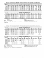
Table 20 -- Electrical Data -- High-Static Motor Units Without Electrical Convenience Outlet
NOMINAL
VOLTAGE
UNIT
48HJ
(V-Ph-Hz)
Min
Max
208/230-3-60
187
284
460-3-60
414
508
575-3-60
518
632
208/230-3-60
187
254
460-3-60
414
508
875-3-60
818
632
208/230-3-60
187
254
460-3-60
414
508
575-3-60
518
632
208/230-3-60
187
254
460-3-60
414
508
575-3-60
518
632
O04
005
006
007
COMPRESSOR
(each)
VOLTAGE
RANGE
Qty
RLA
10.3
5.1
4.2
13.5
6.4
6.4
17.3
9.0
7.1
20.5
9.6
7.7
1
1
1
1
OFM
(each)
LRA
77.0
39.0
31.0
93.0
46.5
40.0
123.0
62.0
50.0
156.0
75.0
56.0
FLA
0.7
0.4
0.4
0.7
0.4
0.4
1.5
0.8
0.8
1.4
0.6
0.6
IFM
COMBUSTION
FAN MOTOR
FLA
5.8
2.6
2.6
5.8
2.6
2.6
7.5
3.4
3.4
7.5
3.4
3.4
MINIMUM UNIT
DISCONNECT
SIZEt
FLA
LRA
19
120
9
60
8
48
23
136
11
68
10
57
30
187
15
94
12
76
34
219
16
107
13
81
POWER SUPPLY*
RLA
0.6
0.3
0.3
0.6
0.3
0.3
0.6
0.3
0.3
0.6
0.3
0.3
MCA
19.4
9.4
7.7
23.4
11.0
10.4
30.6
15.5
12.2
34.8
16
12.8
MOCP**
28
20
20
30
20
20
35
20
20
40
20
20
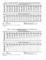
Table 2D -- Electrical Data -- High-Static Motor Units With Electrical Convenience Outlet
UNIT
48HJ
VOLTAGE
RANGE
NOMINAL
VOLTAGE
(V-Ph-Hz)
208/230-3-60
460-3-60
575-3-60
208/230-3-60
460-3-60
575-3-60
208/230-3-60
460-3-60
575-3-60
208/230-3-60
460-3-60
575-3-60
004
005
006
007
FLA
HACR
---
IFM
LRA
---
MOCP
NEC
OFM
MCA
RLA
UL
-------
Min
187
414
518
187
414
518
187
414
518
187
414
518
COMPRESSOR
(each)
Max
254
508
632
254
508
632
254
508
632
254
508
632
Qty
RLA
10.3
5.1
4.2
13.8
6.4
6.4
17.3
9.0
7.1
20.5
9.6
7.7
1
1
1
1
LRA
77.0
39.0
31.0
93.0
46.5
40.0
123.0
62.0
50.0
156.0
75.0
56.0
OFM
(each)
IFM
FLA
0.7
0.4
0.4
0.7
0.4
0.4
1.5
0.8
0.8
1.4
0.6
0.6
FLA
5.8
2.6
2.6
5.8
2.6
2.6
7.5
3.4
3.4
7.5
3.4
3.4
LEGEND
Maximum
Determine
= 1.53%
C @
I1__
,w_,la
I
See table at
is satisfactory
as it is below the maxi-
2%,
contact your
local
electric
utility phase
company
immediately.
MPORTANT:
If the
supply
voltage
imbalance
is more than
POWER
POWER EXHAUST
PART NO,
CRPWREXH021A01
CRPWREXH022A01
CRPWREXH023A01
CRPWREXH028A01
CRPWREXH029A01
CRPWREXH030A01
EXHAUST
ELECTRICAL
DATA
MCA
(230 v)
MCA
(460 v)
MCA
(875 v)
N/A
3.3
N/A
1.7
N/A
1.8
0.9
N/A
1.8
N/A
1.0
N/A
N/A
1.32
N/A
0.88
N/A
0.84
MOCP
(for separate
power source)
15
15
15
15
15
15
N/A -- Not available
NOTE: If a single power source is to be used, size wire to include power
exhaust MCA and MOCR
Check MCA and MOCP when power exhaust is powered through the unit.
Determine the new MCA including the power exhaust using the following
formula:
max voltage deviation from average voltage
average voltage
Example: Supply voltage is 460-3-60.
c
MOCP**
30
20
20
35
20
20
40
20
20
45
25
20
deviation is 7 v.
This amount of phase imbalance
mum allowable 2%.
NOTES:
1. In compliance with NEC requirements for multimotor and combination
load equipment (refer to NEC Articles 430 and 440), the overcurrent
protective device for the unit shall be fuse or HACR breaker. The UL.
Canada units may be fuse or circuit breaker.
2. Electrical data based on 95 F ambient outdoor-air temperature _+10%
voltage.
3. Unbalanced 3-Phase Supply Voltage
Never operate a motor where phase imbalance in supply voltage is
greater than 2%. Use the following formula to determine the pement
voltage imbalance.
% Voltage Imbalance
B
MCA
28.4
12.1
9.8
29.4
13.7
12.6
36.6
18.2
14.4
40.5
18.7
15.0
percent of voltage imbalance.
7
% Voltage Imbalance = 100 x 4_
Maximum Overcurrent Protection
National Electrical Code
Outdoor (Condenser) Fan Motor
Minimum
Circuit
Rated
Load
AmpsAmps
Underwriters' Laboratories
= 100 x
MINIMUM UNIT
DISCONNECT
SIZEt
FLA
LRA
28
124
12
63
10
50
29
140
13
70
12
59
36
192
18
96
14
77
39
224
18
109
15
83
POWER SUPPLY*
RLA
0.6
0.3
0.3
0.6
0.3
0.3
0.6
0.3
0.3
0.6
0.3
0.3
Full Load Amps
Heating, Air Conditioning and
Refrigeration
Indoor (Evaporator) Fan Motor
Locked Rotor Amps
*The values listed in this table do not include power exhaust.
right for power exhaust requirements.
l-Used to determine minimum disconnect per NEC.
**Fuse or HACR circuit breaker.
A
COMBUSTION
FAN MOTOR
MCA New = MCA unit only + MCA of Power Exhaust
For example, using a 48HJD006---5
unit with MCA = 28.9 and MOCP = 38,
with CRPWREXH030A01
power exhaust.
AB = 452 v
BC = 464 v
MCA New = 28.9 amps + 1.6 amps = 30.5 amps
(_
Average Voltage =
AC = 455 v
452 + 464 + 458
3
If the new MCA does not exceed the published MOCE then MOCP would not
change. The M©CP in this example is 35 amps and the MCA New is below
35; therefore the M©CP is acceptable. If "MCA New" is larger than the published MOCP, raise the MOCP to the next larger size. For separate power, the
MOCP for the power exhaust will be 15 amps per NEC.
1371
3
= 457
Determine maximum deviation from average voltage.
(AB) 457 - 482 = 8 v
(BC) 464 - 457 = 7 v
(AC) 487 - 488 = 2 v
)2
I
I
Step 8 -- Adjust Factory-Installed
Options
COBRA TM ENERGY RECOVERY UNITS -- Please lefer
to the supplement provided for information on installing and
operating the factory optional COBRA Energy Recovery
Units. These units are equipped with a factou-installed energy
recove U unit and have different installation and operation procedums than the stan&u'd unit.
HUMIDI-MIZER TM ADAPTIVE DEHUMIDIFICATION
SYSTEM--Humidi-MiZer
system operation can be controlled by field installation of a Carrie>approved humidistat
(Fig. 13).
NOTE: A light commercial Thermidistat TM device (Fig. 14)
can be used instead of the humidistat if desimdi The Thermidistat device includes a thermostat and a humidistat. The humidistat is norm',flly used in applications where a temperature
sensor is already provided (units with PremierLink TM control).
To install the humidistat:
Fig. 13-
Accessory Field-Installed
Humidistat
1. Route humidistat cable through hole provided in unit
comer post.
2. Feed wires through the raceway built into the corner post
to the 24-v bamer located on the left side of the control
box. See Fig. 12. The raceway provides the UL-mquimd
clemance between high-voltage and low-voltage wiring.
3. Use a wire nut to connect humidistat cable into lowvoltage wiring as shown in Fig. 15.
To install Thermidistat device:
1. Route Thermidistat cable through hole provided in
unit corner post.
2. Feed the wires through the raceway built into the
corner post to the 24-v barrier located on the left
side of the control box. See Fig. 12. The raceway
provides the UL-required clearance between high
and low voltage wiring.
Fig. 14 -- Light Commercial Thermidistat
Device
3. Remove evaporator coil access panel. Separate hood and
screen from basepan by removing the 4 screws securing
them. Save all screws.
4. Replace ewtporator coil access panel.
5. Place hood on front of outdoor air opening panel. See
Fig. 18 for hood details. Secure top of hood with the
4 screws removed in Step 3. See Fig. 19.
6. Remove and save 6 screws (3 on each side) from sides of
the manual outdoo>air &_mpel:
7. Align screw holes on hood with screw holes on side of
manual outdoo>air dampel: See Fig. 18 and 19. Secure
hood with 6 screws from Step 6.
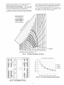
8. Adjust minimum position setting of the damper blade by
adjusting the manual outdoo>air adjustment screws on
the fiont of the dmnper blade. See Fig. 17. Slide blade
vertically until it is in the appropriate position determined
by Fig. 20. Tighten screws.
9. Remove and save screws cunently on sides of hood.
Insert screen. Secure screen to hood using the screws. See
Fig. 19.
3. A field-supplied relay must be installed between the
thermidistat and the Humidi-Mizer circuit (recommended relay: HN612KK324). See Fig. 16. The
relay coil is connected between the DEHUM output
and C (common) of the unit. The relay controls the
Humidi-MiZer solenoid valve and must be wired
between the Humidi-MiZer fuse and the low-pressure switch. Refer to the installation instructions
included with the Carrier Light Commercial Thermidistat device for more information.
MANUAL OUTDOOR-AIR DAMPER -- The outdoor-air
hood and screen me attached to the basepan at the bottom of
the unit for shipping.
Assemb122:
1. Determine quantity of ventilation required for building.
Record amount for use in Step 8.
2. Remove and save outdoor air opening panel and screws.
See Fig. 17.
13
BIU
BLK
_TRAN
3.2
AHPS
_REO
I
LSV]
PNK
•_1_"
CB
CR
DHR
DSV
HR
LPS
LSV
LTLO
---------
L ILO
P NK"O-_-.,,_OP NK
Circuit Breaker
LEGEND
Cooling Relay
Dehumidify Relay
Discharge Solenoid Valve
Heater Relay
Low Pressure Switch
Liquid Solenoid Valve
Low Temperature Lockout
O
IIR1
"I
CRI
Term,ha,
(_-n:]:
d_LPN<'_
BLU_LBLK'E_BLK"_LBV2
I'm
_
OR2
Splice
Factory
BRN--_
1 P _LPS1
K
ke
•
BLK _BLK
I--.Z.J
BRN
__
_
Wiring
Field Control
i,_
BL U,_
_'_
I
_
0RN "_3L
DSV2
p
LPS2
/
6"E_BLU'_O_BLUJ
Wiring
..T--BRN-*,
0R";
TB
Field Power Wiring
I_:x_--
Field Splice
Fig. 15-
Typical Humidi-MiZer TM Adaptive Dehumidification
Humidistat Wiring (208/230-V Unit Shown)
LCT
System
ROOFTOPUNIT
//7--
--
......
EE]-
TSTATWIRES
PINK
_RE_D_ 24V
R1
PINK_ . FROM
LEGEND
CB
LCT
LLSV
LTLO
-i
i
i
Circuit Breaker
Light Commercial Thermidistat
Liquid Line Solenoid Valve
Low Temperature Lockout
HUMIDI-MIZER
LLSV
TM
Device
HUMIDI-MIZER
SYSTEM
Fig. 16- Typical Rooftop Unit with Humidi-Mizer
Adaptive Dehumidification System with Thermidistat Device
OUTDOOR
AIR OPENING
PANEL
HOOD
TOP SCREWS
3 SCREWS
(HIDDEN)
(SIDE)
_
_
MANUAL
OUTDOOR-AtR
ADJUSTMENT
SCREWS
SCREWS
(SCREEN
HOLDERS)
_/
POSITION
SCALE
SE_ING
HOOD
SIDES AND TOPASSEMBLED
DAMPER
BLADE
Fig. 17 -- Damper Panel with Manual Outdoor-Air
Damper Installed
HOOD
SIDE
Fig. 18 -- Outdoor-Air Hood Details
14
SYSTEM
unoccupied). No sensors are supplied with the field-mounted
PremierLink control. The factory-installed
PremierLink
control includes only the supply-air temperature (SAT) sensor and
file outdoor air temperature
(OAT) sensor as stan&lrd. An
indoor air quality (CO2) sensor can be added as an option.
Refer to Table 3 for sensor usage. Refer to Fig. 22 for
PremierLink controller wiring. The PremierLink control may
be mounted in the control panel or tin mea below the control
panel.
NOTE: PremierLink
controller versions 1.3 and later are
shipped in Sensor mode. If used with a thermostat, the PremierLink controller must be configured to Thermostat mode.
SCREW
HOLES
(TOP)
HOOD_
SCREEN
LOCATIOK
(SCREEN
NOT SHOWN)
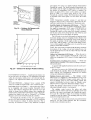
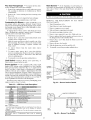
Insttfll file Supply Air Temperature (SAT) Sensor -- When the
unit is supplied with a factory-mounted
PremierLink control,
the supply-air temperature (SAT) sensor (33ZCSENSAT)
is
factory-supplied
and wired. The wiring is routed from the
PremierLink control over the control box, flirough a grommet,
into the fan section, down along the back side of the fan, and
along the fan deck over to the supply-air opening.
Fig. 19 -- Outdoor-Air Damper with
Hood Attached
0.6
The SAT probe is wire-tied to file supply-air opening (on the
horizontal opening end) in its shipping position. Remove the
sensor for installation. Re-position the sensor in the flange of
file supply-air opening or in the supply air duct (as required by
local codes). Drill or punch a l/2-in, hole in the flange or duct.
Use two field-supplied, self-drilling screws to secure the sensor
probe in a horizontal orientation.
0.5
_"
0,4
UI
o3
NOTE: The sensor must be mounted in the dischmge airstream
downstream of the cooling coil and any heating devices. Be
sure the probe tip does not come in contact with tiny of the unit
or heat surfaces.
03
LU
m
13.
LU
0.3
>
0.2
Outdoor Air Temperature (OAT) Sensor -- When the unit is
supplied with a factoly-mounted
PremierLink
control, the
outdoor-air temperature (OAT) sensor is factory-supplied
and
wired.
Z
Install the Indoor Air Quality (COe) Sensor -optional indoor air quality (CO2) sensor according
turer specifications.
o
o
1
2
3
4
5
6
7
A separate field-supplied
er the CO2 sensoc
OUTDOOR AIRFLOW (cfm x 100)
Fig. 20 -- Outdoor-Air
CONVENIENCE
OUTLET
let provides power for rooftop
safety, the convenience outlet
connect is off. Adjacent unit
tool s.
Damper Position Setting
transformer
Mount the
to manufac-
must be used to pow-
Wire the CO2 sensor to the COM and IAQI terminals of J5
on the PremierLink controllec Refer to the PremierLink Installation, Start-up, and Configuration
Instructions
for detailed
wiring and configuration information.
Enthalpy
Sensors and Control
-- The enthalpy control
(HH57AC077)
is supplied as a field-installed accessory to be
used with the EconoMiSer2 damper control option. The outdoor air enthalpy sensor is part of the enthalpy control. The
septu'ate field-installed
accessory return air enthalpy sensor
(HH57AC078)
is required for differentkd enthalpy control.
-- An optiomfl convenience outuse. For maintenance personnel
power is off when the unit disoutlets may be used for service
NOVAR CONTROLS
-- Optiomd
Novar
controls
(ETM
3051 ) me available for replacement or new construction jobs.
PREMIERLIN K TM CONTROL
-- The PremierLink controller is compatible
with Carrier Comfort Network®
(CCN)
devices. This control is designed to tdlow users the access and
ability to change factory-defined
settings, thus expanding the
function of file standmd unit control board. Carder's diagnostic
standard tier display tools such as Navigato( r_'_ or Scrolling
Marquee can be used wifli the PremierLink controllec
The PremierLink controller (see Fig. 21A and 21B) requires
the use of a Carrier electronic thermostat or a CCN connection
for time broadcast to initiate its internal timeclock. This is
necessmy for broadcast of time of &ty functions (occupied/
NOTE: The enthalpy control must be set to the "D" setting for
differential enthalpy control to work properly.
The enthtdpy
control receives the indoor and return
enthalpy from the outdoor and return air enthtdpy sensors and
provides a @ contact switch input to the PremierLink controllec Locate the controller in place of an existing economizer
controller or near the actuatoc The mounting plate may not be
needed if existing bracket is used.
A closed contact indicates that outside air is preferred to the
return aic An open contact indicates that the economizer
should remain tit minimum position.
15
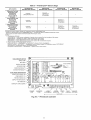
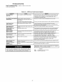
Table 3OUTDOOR
TEMPERATURE
APPLICATION
Differential
AIR
SENSOR
PremierLink
RETURN
TEMPERATURE
TM
Sensor Usage
AIR
SENSOR
OUTDOOR
AIR
ENTHALPY
SENSOR
RETURN AIR
ENTHALPY
SENSOR
--
--
Dry Bulb
Temperature
with
PremierLink*
(PremierLink
requires
4-20 mA
Actuator)
Required -33ZCT55SPT
Included -CRTEMPSN001A00
or Equivalent
Single Enthalpy
with
PremierLink*
(PremierLink
requires
4-20 mA
Actuator)
Included -Not Used
--
orHH57AC077Equivalent
Differential
Enthalpy
with PremierLink*
(PremierLink
requires
4-20 mA
Actuator)
Included -Not Used
--
Required -HH57AC077
or Equivalent
Required
---
Required -HH57AC078
or Equivalent
*PremierLink
control requires Supply Air Temperature
sensor 33ZCSENSAT
and
Outdoor Air Temperature
sensor CRTEMPSN001A00
-- Included with factory-installed
PremierLink control;
field-supplied
and field-installed
with field-installed
PremierLink control.
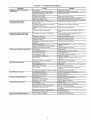
NOTES:
1. CO2 Sensors (Optional):
33ZCSENCO2
-- Room sensor (adjustable).
Aspirator box is required for duct mounting of the sensor.
33ZCASPCO2
-- Aspirator box used for duct-mounted
CO2 room sensor.
33ZCT55CO2
-- Space temperature
and CO2 room sensor with override.
33ZCT56CO2
-- Space temperature
and CO2 room sensor with override and set point.
2. All units include the following Standard Sensors:
Outdoor-Air Sensor -- 50HJ540569
-- Opens at 67 F, closes at 52 F, not adjustable.
Mixed-Air Sensor -- HH97AZ001
-- (PremierLink
control requires Supply Air Temperature
sensor 33ZCSENSAT
and Outdoor Air Temperature
Sensor CRTEMPSN001A00)
Compressor
Lockout Sensor -- 50HJ540570
-- Opens at 35 F, closes at 50 E
HVAC SENSOR
INPUTS
0
0
(
SL
DUAL
MODE
SENSOR/STAT
REMOTE OCCUPANCY
COMP SAFETY (Y1) ._
FIRE SHUTDOWN
(Y2) Z
SUPPLY FAN STATUS (Wl)
NOT USED
ENTHALPY
STATUS (ENTk
/
CCN/LEN
PORT
NAVIGATOR
PORT
,/
4-20MA
ECONOMIZER
t
INDOOR
FAN MOTOR
"4 "-4 "-..
COMPR
1& 2
OUTPUTS
Fig. 21A -- PremierLink Controller
16
HEAT
LOW/HIGH
EXHAUST
RVSVALVE
©©
PREMIERLINK
CONTROL
HINGED
DOOR
PANEL
PREMIERLINK
COVER
Fig. 21B -- PremierLink
OUTD_R
AiR
i
' GRAY
SENSOR
Comm
[
:
•
BLK
i
i RED,
Economi$er2
4 - 20mA
Controller (Installed)
'
CCN
ENTHALPY
TM
[
7F"
_
\L_
6(]t G w_
WHT
8_[)..............
.... BLK
7
",C
'_(][j
.............................................................................................................
8 _-lhX
LEGEND
:
[
::::::::Q
0
0
_"
RETURN
AIR
ENTHALPY
SENSOR
COMMS
OAT
PWR
RTU
SAT
TB
-------
\
Communications
Outdoor Air Temperature Sensor
Power
Rooftop Unit
Supply Air Temperature Sensor
Terminal Block
Fig. 22 -- Typical PremierLink Controls
]7
/
RTU Terminal
Board
Wiring
Outdoor
Air
Enthalpy
Sensor/Enthalpy
Controller
(HH57AC077)
-- To wire the outdoor tfir enthalpy sensor.
perform the following (see Fig. 23 and 24):
NOTE: The outdoor air sensor can be removed from the back
of the enth_dpy controller and mounted remotely.
1. Use a 4-conductor.
18 or 20 AWG cable to connect the
enthalpy control to the PremierLink controller and power
tmnsformec
2.
2.
Connect the following 4 wires from the wire hmness
located in rooftop unit to the enthalpy controller:
a. Connect the BRN wire to the 24 vac terminal (TRI)
on enthalpy control and to pin 1 on 12-pin harness.
b. Connect the RED wire to the 24 vac GND terminal
(TR) on enth_dpy sensor and to pin 4 on 12-pin
hmness.
c. Connect the GRAY/ORN
wire to J4-2 on PremierLink controller and to terminal (3) on enthalpy sensoc
d. Connect the GRAY/RED
wire to J4-1 on PremierLink controller and to terminal (2) on enthalpy sensoc
The box with the economizer
hood components
is
shipped in the compartment behind the economizer
The
EconoMiSer
IV controller is mounted
on top of the
EconoMiSer [V in the position shown in Fig. 25. The
optiomd EconoMiSer2 with 4 to 20 mA actuator signal
control does not include the EconoMi$er IV controllec
To remove the component box from its shipping position,
remove the screw holding the hood box bracket to the top
of the economizec Slide the hood box out of the unit. See
Fig. 28.
HH57AC077
ENTHALPY
CONTROL AND
OUTDOOR AIR
ENTHALPYSENSOR
HH57AC078 ENTHALPY
SENSOR (USED WITH
ENTHALPY CONTROL
FOR DIFFERENTIAL
ENTHALPY OPERATION)
NOTE: [f installing in a Carrier rooftop, use the two gray wires
provided from the control section to the economizer to connect
PremierLink controller to terminals 2 and 3 on enth_dpy sensoc
Return Air Enthalpy Sensor -- Mount the return-air enthalpy
sensor (HH57AC078)
in the return-air duct. The return air
sensor is wired to the enth_dpy controller (HH57AC077).
The
outdoor enth_dpy changeover set point is set at the controller.
To wire the return air enthalpy sensor perform the following (see Fig. 23):
1. Use a 2-conductor,
18 or 20 AWG. twisted pair cable to
connect the return air enthalpy sensor to the enthalpy
controller.
2. At the enthalpy control remove the factory-installed
resistor from the (SR) and (+) termimds.
3. Connect the field-supplied
RED wire to (+) spade
connector on the return air enthalpy sensor and the (SR+)
terminal on the enth_dpy controllel: Connect the BLK
wire to (S) spade connector on the return air enthalpy
sensor and the (SR) terminal on the enthalpy controller
OPTIONAL
ECONOM[$ER
IV AND ECONOM[$ER2
-See Fig. 25 for EconoMiSer
IV component
locations. See
Fig. 26 for EconoMiSer2 component locations.
MOUNTING PLATE
Fig. 24 -- Differential Enthalpy Control,
Sensor and Mounting Plate (33AMKITENT006)
EOOv Oo E
OUTSIDE
TEMPERATURE
........
g
ACTUATOR
AIR
AI / / LOWAMO,ENT
HARNESS
_
,_
_r,_
Y
,_=
/
SENSOR
SENSOR
/
NOTE: These instructions
are for installing the optiomd
EconoMiSer IV and EconoMi$er2 only. Refer to the accessory
EconoMiSer IV or EconoMiSer2 inst_dlation instructions when
field installing an EconoMiSer [V or EconoMi$er2 accessory.
1. To remove the existing unit filter access panel, rgfise the
panel and swing the bottom outwmd. The panel is now
disengaged
from the track and can be removed. See
Fig. 27.
BRN
RED
SRCq+D- ---q
Fig. 25 --
EconoMi$er
0
IV Component
_
-/
Locations
OUTDOOR
AIR HOOD
A6O
soO +13--
TRra']TRI__
ENTHALPYCONTROLLER
x_
BLK r_
t
ENTHALPY
(OUTDOORAIR
SENSOR)
RED
'
FIs (RETURNAIRI
FI +
--
ECONOMI$ER2_
HOOD
ENTHALPY
SENSOR
BRACKET
GRAY/ORN
PWO
,,.WIRE HARNESS
LED
GRAY/RED
jIN
UNIT
NOTES:
1. Remove factory-installed
jumper across SR and +
wires from return air sensor.
2. Switches shown in high outdoor air enthalpy state.
close on low outdoor air enthalpy relative to indoor air
3. Remove sensor mounted on back of control and
airstream.
before connecting
Terminals 2 and 3
enthalpy.
locate in outdoor
/
BAROMETRIC
RELIEF
DAMPER
Fig. 23 -- Outdoor and Return Air Sensor Wiring
Connections
for Differential
Enthalpy Control
GEAR DRIVEN
DAMPER
Fig. 26 -- EconoMi$er2 Component Locations
18
FILTER
ACCESS
PANEL
SIDE
PANEL
_COMPRESSOR
ACCESS
PANEL
OUTDOOR-AIR
INDOOR
COIL
Fig. 27-
Typical
Access
OPENING
AND
ACCESS
PANEL
TOP
SIDE
PANEL
Panel Locations
N
INDOOR
COIL
ACCESS
PANEL
INDOOR
COIL
",
"',
PANEL
Fig. 29 -- Indoor Coil Access Panel Relocation
HOOD BOX
BRACKET
i I
ii
11
II
TOP
PANEL
iI
I
I
I
INDOOR
ACCESS
I
/
0
COIL
PANEL
1I
i I
Fig. 28-
LEFT
Hood Box Removal
SIDE
installed on the unit, the hood shipped with the unit will not
be used and must be discarded. Save the aluminum
filter
I IMPORTANT:
If the power exhaust accessory is to be
for use in the power exhaust hood assembly.
3.
4.
5.
6.
7.
8.
9.
10.
The indoor coil access panel will be used as the top of the
hood. Remove the screws along the sides and bottom of
the indoor coil access panel. See Fig. 29.
Swing out indoor coil access panel and insert the hood
sides under the panel (hood top). Use the sclews provided
to attach the hood sides to the hood top. Use screws provided to attach the hood sides to the unit. See Fig. 30.
HOOD
Fig. 30 --
DIVIDER
Outdoor-Air
Hood Construction
17 1/4"
Remove the shipping tape holding the economizer barometric relief &_mper in place.
Insert the hood divider between the hood sides. See
Fig. 30 and 31. Secure hood divider with 2 screws on
each hood side. The hood divider is also used as the bottom tilter rock for file aluminum filter.
Open the tilter clips which are located underneath the
hood top. Insert the aluminum tilter into the bottom tilter
rack (hood divider). Push the tilter into position past the
open filter clips. Close the filter clips to lock the tilter into
place. See Fig. 31.
Caulk the ends of the joint between the unit top panel and
the hood top. See Fig. 29.
Replace the filter access panel.
Install all EconoMi$er
IV accessories.
wiring is shown in Fig. 32. EconoMi$er2
in Fig. 33.
HOOD
ALUMINUM
FI_ER
EconoMi$er
IV
wiring is shown
BAROMETRIC
RELIEF
FILTER
CLIP
Barometric flow capacity is shown in Fig. 34. Outdoor air
leakage is shown in Fig. 35. Return air pressure drop is shown
in Fig. 36.
Fig. 31 -- Filter Installation
19
FOR OCCUPANCY CONTROL
REPLACE JUMPER WITH
FIELD-SUPPLIED
TIME CLOCK
/
8LK
ECONO_I
ZZR
MOTOR
(F]ELD
ACCESSORY)
REMOTE MI_
POSiI[O_
POT
WHT_
REO
IR_M0_FOT
71_ 0_-m}--
PL6-R
FOR STD
UNIT
IAO SEICSOR
FIELD
]ICSTALLED
_
_
--GRyJ
(R0f
OAr TEMPI
E_T_AL_Y DE_SOR
USED}
RED
L_ -/FIELD ACCESDORYI
RAT/ENrHAIPY SE_DOR
2_
BLU
FIELD
FIELD
SPLICE,
3_
E
SPLICE
BRN
4<
IROT gSEOl
TAN
5_
GRY
9_
ORG
TO
LEGEND
DCV-IAQ -LA -OAT-POT-RAT--
Demand Controlled Ventilation
Indoor Air Quality
Low Ambient Lockout Device
Outdoor-Air Temperature
Potentiometer
Return-Air Temperature
PWR EXHAUST
ACCESSORY
Potentiometer Defaults Settings:
Power Exhaust
Middle
Minimum Pos.
Fully Closed
DCV Max.
Middle
DCV Set
Middle
Enthalpy
C Setting
(_of USED}
!_
NOTES:
1. 620 ohm, 1 watt 5% resistor should be removed only when using differential
enthalpy or dry bulb.
2. If a separate field-supplied 24 v transformer is used for the IAQ sensor power
supply, it cannot have the secondary of the transformer grounded.
3. For field-installed
remote minimum position POT, remove black wire jumper
between P and P1 and set control minimum position POT to the minimum
position.
Fig. 32 -- EconoMi$er IV Wiring
BLACK
4
3
5
f
2
500 OHM
_[_>1
8
RESISTOR?
J
NOTE 1
T
o
I
I
'_RUN
- e--II
NOTE3
J
-{-
III--
I ....
_
I
I
I
i
I
VIOLET
7
RED
1
J
10
I
I
50HJ540573
ACTUATOR
ASSEMBLY
6
PINK
s
OPTIONAL CO2
SENSOR 4 - 20 mA
OUTPUT
11
W
>-
9
WHITE
DIRECT DRIVE
ACTUATOR
12
ECONOMIZER2
NOTES:
1. Switch on actuator must be in run position for economizer to operate,
2. PremierLink TM control requires that the standard 50HJ540569 outside-air sensor be replaced by either the CROASENR001A00
enthalpy sensor.
3. 50HJ540573 actuator consists of the 50HJ540567 actuator and a harness with 500-ohm resistor,
Fig. 33 -- EconoMi$er2 with 4 to 20 mA Control Wiring
20
PLUG
dry bulb sensor or HH57A077
2500
W
z
2000
w
1500
W
m
SUPPLY AIR
TEMPERATURE
SENSOR
MOUNTING
f
1000
o
I
500
LOCATION
0
Z
0.05
0] 15
STATIC
0.25
PRESSURE
SUPPLY AIR
TEMPERATURE
SENSOR
(in. wg)
Fig. 34 -- Barometric Flow Capacity
v
Fig. 37 -- Supply Air Sensor Location
"5
30
LU
h-
z_
25
cc
20
Table 4 -- Supply Air Sensor Temperature/
Resistance Values
LU
D_
I--
15
LU
LU
EL
10
Ca
5
©
z
0
D
TEMPERATURE
-58
0.13
0.20
0.22
0.25
STATIC
LL
0.30
0.35
PRESSURE
Fig. 35 -- Outdoor-Air
0.40
0.45
0.50
(in. wg)
Damper Leakage
6ooe
w
500_
Z
m
400_
w
3000
w
w
L
©
2000
100_
Z
0
S
RESISTANCE (ohms)
200,250
-40
-22
q
D
(F)
0.05
0.10
0.15
0.20
0.25
0.30
0.35
L
STATIC
PRESSURE
(in. wg)
Fig. 36 -- Return-Air Pressure Drop
ECONOMI$ER
IV STANDARD
SENSORS
ECONOMISER
Outdoor Air Temperature
(OAT) Sensor -- The outdoor air
temperature sensor (HH57AC074)
is a 10 to 20 mA device
used to measure the outdoor-air temperature. The outdoor-air
temperature is used to determine when the EconoMiSer IV can
be used for free cooling. The sensor is factory-installed
on the
EconoMiSer IV in the outdoor airstream. See Fig. 25. The operating range of temperature measurement is 40 to 100 E
-4
14
29,091
16,590
32
50
68
9,795
5,970
3,747
77
86
3,000
2,416
104
122
140
1,597
1,080
746
158
176
525
376
185
194
321
274
212
230
203
153
248
257
116
102
266
284
89
70
302
55
IV CONTROL
MODES
IMPORTANT:
The
optional
EconoMiSer2
does
not
include a controllel:
The EconoMiSer2
is operated
by a 4 to
20 mA signN
from
(such as PremierLink
information.
an existing
TM
control).
field-supplied
See Fig. 33
controller
for wiring
Determine fl3e EconoMiSer IV control mode before set up of
the control. Some modes of operation may require different sensors. Refer to Table 5. The EconoMiSer IV is supplied from the
factory with a supply air temperature sensor and an outdoor air
temperature
sensol:
This allows
for operation
of the
EconoMiSer IV with outdoor air dry bulb changeover control.
Additional accessories can be added to allow for diffelent types
of changeover control and operation of the EconoMiSer IV and
unit.
Supply Air Temperature
(SAT) Sensor
-- The supply air
temperature sensor is a 3 K themristor located at the inlet of the
indoor fan. See Fig. 37. This sensor is factory installed. The operating range of temperature measurement is 0 ° to 158 E See
Table 4 for sensor temperature/resistance
v_dues.
The temperature sensor looks like an eyelet terminal
wires running to it. The sensor is located in the "crimp
and is sealed fi_m moisture.
100,680
53,010
with
end"
Outdoor Air Lockout
Sensor
-- The EconomiSer
IV is
equipped with an mnbient temperature lockout switch located
in the outdoor air stream which is used to lockout the compressors below a 42 F ambient temperature. See Fig. 25.
Outdoor DLy Bulb Changeover
-- The standard controller is
shipped from the facto q configured
for outdoor dlT bulb
changeover control. The outdoor air and supply air temperature
sensors tue included as stan&ud. For this control mode, the
21
outdoor
temperature
is comptu'ed
to anadjustable
setpoint
selected
onthecontrol.
If theoutdoor-air
temperature
isabove
thesetpoint,theEconoMiSer
IV will adjusttheoutside
air
dmnpers
tominimum
position.
If theoutdoor-air
temperature
is
below
thesetpoint,theposition
oftheoutdoor
airdampers
will
becontrolled
toprovide
fleecooling
usingoutdoor
air.When
inthismode,
theLEDnexttofilefreecooling
setpointpotentiometer
will beon.Thechangeover
temperature
setpointis
controlled
bythefreecooling
setpointpotentiometer
located
onthecontrol.
See
Fig.38.Thescale
onthepotentiometer
isA,
B,C,andD. SeeFig.39fortheconesponding
temperature
changeover
values.
19
,,
i
[
17
16- _
LED ON
-LED OF[
15
_LED
ON
13
_m.
12
LED ON-- --
11
10
LED OFF
I
9
Differential Dry Bulb Control -- For differential dry bulb
control the standard outdoor dry bulb sensor is used in conjunction with an additional accessory dry bulb sensor (part number
CRTEMPSN002A00).
Tile accessory sensor must be mounted
in the return ailstream. See Fig. 40. Wiring is provided in the
EconoMiSer IV wiring harness. See Fig. 32.
4O
46
5O
55
60
65
70
75
80
85
90
Accessories
Outdoor Air
Dry Bulb
Differential
Dry Bulb
Single
ECONOMI$ER
_
CONTROLLER
/
AIR
_
GROMMET
I
,
I
I
HH57AC078
HH57AC078
and
CRENTDIF004A00*
SENSOR
_f_-
RETURNAIR
RETURN DUCT
(FIELD-PROVIDED)
CO2 for DCV
Control using a
Wall-Mounted
CO2 Sensor
33ZCSENCO2
Fig. 40 -- Return Air Temperature or Enthalpy
Sensor Mounting Location
and
33ZCASPCO2**
33ZCSENCO2t
CRCBDIOX005A00tt
I_
I
Outdoor Enthalpy Changeover
-- For enthalpy control, accessory enthalpy sensor (p_u-t number HH57AC078)
is required. Replace the standard outdoor @ bulb temperature sensor with file accessory enthalpy sensor in the same mounting
location. See Fig. 25. When the outdoor air enthalpy rises
above the outdoor enthalpy changeover set point, the outdoorair damper moves to its minimum position. Tile outdoor
enthalpy changeover set point is set with the outdoor enth_dpy
set point potentiometer on file EconoMiSer IV controllel: The
set points are A, B, C, and D. See Fig. 41. The factory-installed
620-ohln jumper must be in place across terrainals SR and SR+
on file EconoMiSer IV controllel: See Fig. 25 and 42.
*CRENTDIF004A00
and CRTEMPSN002A00
accessories
are used on
many different base units. As such, these kits may contain parts that
will not be needed for installation.
t33ZCSENCO2
is an accessory CO2 sensor.
**33ZCASPCO2
is an accessory
aspirator
box required
for ductmounted applications.
ttCRCBDiOX005A00
is an accessory that contains both 33ZCSENCO2
and 33ZCASPCO2
accessories.
EXHAUST
FAN SET POINT
LED LIGHTS
WHEN EXHAUST
CONTACT IS MADE
Differential Enthalpy Control
-- For differential
enthalpy
control, the EconoMiSer IV controller uses two enthalpy sensors (HH57AC078
and CRENTDIF004A00),
one in the outside air and one in the return air duct. The EconoMiSer IV
controller compmes file outdoor air enthalpy to the return air
enthalpy to determine
EconoMi$er
IV use. Tile controller
selects the lower enthalpy air (return or outdoor) for cooling.
For example, when file outdoor air has a lower enthalpy than
the return air. the EconoMi$er IV opens to bring in outdoor air
for free cooling.
MINIMUM DAMPER
POSITION SETTING
MAXIMUM DAMPER _
DEMAND CONTROL
VENTILATION SET POINT
LED LIGHTS WHEN_
DEMAND CONTROL
VENTILATION
INPUT
ISABOVE SET POINT
DEMAND CONTROL
VENTILATION SET POINT
LED LIGHTS WHEN
Replace the standard outside air dry bulb temperature sensor with file accessory enthalpy sensor in the same mounting
location. See Fig. 25. Mount the return air enthalpy sensor in
the return air duct. See Fig. 40. Wiring is provided in the
EconoMiSer IV wiring harness. See Fig. 32. The outdoor enthalpy changeover set point is set with the outdoor enthalpy set
point potentiometer
on the EconoMiSer IV controllel: When
AIR IS
FREE
COOLING
SUITABLE
FOR
CHANGEOVER
Fig. 38 --
7
Required
CRTEMPSN002A00*
Differential
Enthalpy
OUTDOOR
]_
ECONOMI$ER
None. The outdoor air dry bulb sensor
is factory installed.
Enthalpy
CO2 for DCV
Control using a
Duct-Mounted
CO2 Sensor
100
Fig. 39 -- Outside Air Temperature
Changeover Set Points
Table 5 -- EconoMi$er IV Sensor Usage
ECONOMI$ER
IV WITH OUTDOOR
DRY BULB SENSOR
"%
DEGREES FAHRENHEIT
In this mode of operation, the outdoor-air temperatme
is
compared to the return-air temperature and the lower temperature airsheam is used for cooling. When using this mode of
changeover control, turn the enthalpy setpoint potentiometer
fully clockwise to the D setting. See Fig. 38.
APPLICATION
95
ENTHALPY
SET POINT
EconoMiSer
IV Controller
and LED Locations
Potentiometer
22
usingthismode
of changeover
control,
turntheenthalpy
setpointpotentiometer
fullyclockwise
totheD setting.
AQI terminals of file controller Adjust the DCV potentiometers to correspond to the DCV voltage output of file indoor air
quality sensor at the user-determined
set point. See Fig. 43.
Indoor Air Quality (IAQ) Sensor Input -- The IAQ input
can be used for demand control ventilation control based on the
level of CO2 measured in the space or return air duct.
If a separate field-supplied transformer is used to power the
IAQ sensor, the sensor must not be grounded
or the
EconoMi$er IV control board will be damaged.
Mount the accessory IAQ sensor according to manufacturer
specifications. The IAQ sensor should be wired to the AQ and
CONTROL
CURVE
CONTROL
85
90
95
100
105
110
(29)
(32)
(35)
(38)
(41)
(43)
POINT
APPROXI°F(°C)
AT 50% RH
A
73123)
B
70121)
C
D
67119 )
63(17)
\
\
\
\
\
HIGH
35
40
45
50
55
60
65
70
75
80
85
90
95
100
\
105
(2)
(4)
(7)
(10)
(13)
(16)
(18)
(21)
(24)
(27)
(29)
(32)
(35)
(38)
(41)
APPROXIMATE
DRY BULB TEMPERATURE--
Fig. 41 --
Enthalpy
LIMIT
CURVE
110
(43)
°F (°C)
Changeover
Set Points
CO 2 SENSOR MAX RANGE SETTING
TRIP-1
6000
T_
5000
Vac
24T_24
HO
......
z
COM
Vac
2
4000
+800
+900
@
ppm
ppm
3000
Z
2
z
5
......
_
<
4
EF1
Fig. 43
..................................................
J
EconoMi$er
ppm
o
2
Fig. 42 --
ppm
_1000
1000
3
4
5
6
7
DAMPER VOLTAGE FOR MAX VENTILATION
EF_
+1100
2000
W
IV Control
23
--
CO2
Sensor
Maximum
8
RATE
Range
Setting
Damper Movement -- Damper movement trom full open to
full closed (or vice versa) takes 2112minutes.
Thermostats -- The EconoMi$er IV control works with conventiomd thermostats that have a YI (cool stage 1), Y2 (cool
stage 2), Wl (heat stage 1), W2 (heat stage 2), and G (fan). The
EconoMi$er IV control does not support space temperature
sensors. Connections are made at the thermostat termimd connection board located in the main control box.
Exhaust Set Point Adjustment
-- The exhaust set point will
determine when the exhaust fan runs based on dmnper position
(if accessory power exhaust is installed). The set point is modified with the Exhaust Fan Set Point (EXH SET) potentiometer
See Fig. 38. The set point represents the damper position above
which the exhaust fans will be turned on. When there is a call
for exhaust, the EconoMiSer IV controller provides a 45 _+15
second delay before exhaust fan activation to allow the dampers to open. This delay _fllows file damper to reach the appropriate position to avoid unnecessary fan overload.
Occupancy Control -- The facto U default configuration for
the EconoMi$er IV control is occupied mode. Occupied status
is provided by the black jumper fiom terminal TR to terminal
N. When unoccupied mode is desired, install a field-supplied
time clock function in place of the jumper between TR and N.
See Fig. 32. When the time clock contacts me closed, the
EconoMi$er IV control will be in occupied mode. When the
time clock contacts are open (removing the 24-v signal from
terminal N), the EconoMi$er IV will be in unoccupied mode.
Minimum Position Control -- There is a minimum damper
position potentiometer on the EconoMiSer [V controllel: See
Fig. 38. The minimum damper position maintains the minimum airflow into the building during the occupied period.
When using demand ventihttion, the minimum dmnper position represents the minimum ventilation position for VOC
(volatile organic compound)
ventilation requirements.
The
maximum demand ventilation position is used for fully occupied ventilation.
When demand
minimum position
cupied ventilation
position should be
Demand Controlled Ventilation (DCV) -- When using the
EconoMi$er IV for demand controlled ventilation, them are
some equipment selection criteria which should be considered.
When selecting the heat capacity and cool capacity of the
equipment, the maximum ventilation rote must be evaluated for
design conditions. The maximum damper position must be calculated to provide the desired fresh air
Typically the maximum ventilation rate will be about 5 to
10% more than the typical cfin required per person, using
normal outside air design criteria.
ventilation control is not being used, the
potentiometer should be used to set the ocposition. The maximum demand ventilation
turned fully clockwise.
Adjust the minimum position potentiometer
to allow the
minimum mnount of outdoor aik as required by local codes, to
enter the building. Make minimum position adjustments with
at least 10 F temperature difference between the outdoor and
return-air temperatures.
To determine the minimum
following procedure:
position
setting,
perform
1. Calculate the appropriate mixed air temperature
following formula:
OA
RA
(To x l---ff_ ) + (TR x _
= TM
A proportional anticipatory strategy should be taken with
the following conditions: a zone with a large area, varied occupancy, and equipment that cannot exceed the required ventilation rate at design conditions. Exceeding the required ventilation rate means the equipment can condition air at a maximum
ventilation rate that is greater than the required ventilation rate
for maximum occupancy. A proportional-anticipato U strategy
will cause the fresh air supplied to increase as the room CO2
level increases even though the CO2 set point has not been
reached. By the time the CO2 level roaches the set point, the
damper will be at maximum ventilation and should maintain
the set point.
In order to have the CO2 sensor control the economizer
damper in this manner, fil.'stdetermine the damper voltage output for minimum or base ventilation. Base ventilation is the
ventilation required to remove contmninants during unoccupied periods. The following equation may be used to determine
the percent of outside-air entering the building for a given
damper position. For best results there should be at least a
10 degree difference in outside and return-air temperatures.
the
using the
To = Outdoor-Air Temperature
OA = Percent of Outdoor Air
TR = Return-Air Temperature
RA = Percent of Return Air
TM = Mixed-Air
Temperature
As an example, if local codes require 10% outdoor
during occupied conditions, outdoor-air temperature
60 E and return-air temperature is 75 E
(60 x .10) + (75 x .90) =73.5
air
is
F
2.
Disconnect
TI.
the supply air sensor
3.
Ensure that
terminals P
used, make
Fig. 32 and
turned fully
Connect 24
the factory-installed jumper is in place across
and PI. If remote damper positioning is being
sure that the terminals are wired according to
that the minimum position potentiometer
is
clockwise.
vac across terminals TR and TRI.
4.
5.
from terminals
T and
OA
RA
(To x l---ff_-) + (TR x _
To = Outdoor-Air Temperature
OA = Percent of Outdoor Air
TR = Return-Air Temperature
RA = Percent of Return Air
Carelhlly adjust the minimum position potentiometer
until the measured supply air temperature matches the
calculated value.
TM = Mixed-Air Temperature
Once base ventilation has been determined, set the minimum damper position potentiometer to the correct position.
The same equation can be used to deterlnine the occupied or
maximum ventilation rate to the building. For example, an output of 3.6 volts to the actuator provides a base ventilation rate
of 5% and an output of 6.7 volts provides the maximum ventilation rate of 20% (or base plus 15 cfm per person). Use Fig. 43
to determine the maximum setting of the CO2 sensol: For example, a 1100 ppm set point relates to a 15 cfm per person design. Use the 1100 ppm curve on Fig. 43 to find the point when
the CO2 sensor output will be 6.7 volts. Line up the point on the
graph with the left side of the chart to determine that the range
configuration for the CO2 sensor should be 1800 ppm. The
6. Reconnect the supply air sensor to termimfls T and TI.
Remote control of the EconoMiSer IV damper is desirable
when requiring
additiomfl
tempormy
ventilation.
If a
field-supplied remote potentiometer (Honeywell part number
$963B1128)
is wired to the EconoMiSer IV controllek the
minimum position of the damper can be controlled from a remote location.
To control the minimum damper
the factory-installed jumper on the
EconoMiSer IV controllel: Wire the
ter to the P and PI terminals on the
See Fig. 42.
= TM
position remotely, remove
P and PI terminals on the
field-supplied potentiomeEconoMi$er IV controller.
24
EconoMiSer
IV controller
will outputthe6.7voltsfiomthe
CO2sensor
totheactuator
whentheCO2concentration
inthe
space
isfit1100ppm.TheDCVsetpointmaybeleftfit2volts
sincethe CO2sensorvoltagewill be ignoredby the
EconoMiSer
IV controller
untilitrisesabove
the3.6voltsettingoftheminimum
position
potentiometer
Oncethefullyoccupied
dmnper
position
hasbeendetermined,
setfilemaximum
damper
demand
controlventilation
potentiometer
tothisposition.
Donotsettofilemaximum
positionasfliiscanlesultinover-ventilation
tothespace
findpotentialhigh-humidity
levels.
heating and cooling processes are morn than adequae to mmove the humidity loads for most commemial applications.
If normal rooftop heating and cooling operation is not adequate for the outdoor humidity level, fin energy recovery unit
and/or a dehumidification
option should be considered.
Step 9-
Adjust Evaporator-Fan
evaporator-fan
Speed
--Adjust
speed to meet jobsite conditions.
Tables 7 and 8 show fan rpm fit motor pulley settings.
Tables 9 and 10 show maximum amp draw of belt-di'ive motol:
Table 11 shows sound data. Refer to Tables 12-29 for performance data. See Table 30 for accessory static pressure drop.
See Fig. 44 for the Humidi-MiZer r_q system static pressure
diops.
C02 Sensor Configuration
-- The CO2 sensor has preset
standard voltage settings flint can be selected anytime after the
sensor is powered up. See Table 6.
Use setting 1 or 2 for Carrier equipment. See Table 6.
1. Pless Clear and Mode buttons. Hold fit least 5 seconds
until the sensor enters the Edit mode.
BELT-DRIVE MOTORS -- Fan motor pulleys are facto q set
for speed shown in Table 1. Check pulley alignment find belt
tension prior to start-up.
2.
Pless Mode twice. The STDSET
3.
Use file Up/Down
Table 6.
NOTE: Befole adjusting fan speed, make sure the new fan
speed will provide an air temperature rise range as shown in
Table 1.
4.
Pless Enter to lock in the selection.
5.
Pless Mode to exit and resume normal operation.
Menu will appem:
button to select the pleset numbel: See
To change fan speed:
1. Shut off unit power supply, tag disconnect.
The custom settings of the CO2 sensor can be changed anytime after the sensor is energized. Follow the steps below to
change file non-stan&trd settings:
1. Pless Clear and Mode buttons. Hold fit least 5 seconds
until the sensor enters the Edit mode.
2.
Pless Mode twice. The STDSET
3.
Use the Up/Down
and press Entec
4.
Use the Up/Down button to toggle through each of the
nine variables, stinting with Altitude, until the desired setting is reached.
5.
6.
button to toggle to the NONSTD
menu
Table
OUTPUT
6
--
002
(cfm/Peraon)
1
2
3
4
5
3.
Ix_osen movable
4.
Screw movable flange toward fixed flange to increase
speed and away from fixed flange to decrease speed.
Increasing fan speed increases load on motol: Do not
exceed maximum speed specified in Table 1.
5.
Set movable flange at nearest keyway of pulley hub and
tighten setscrew. (See Table 1 for speed change for each
lull turn of pulley flange.)
1. Ix_osen fan motor mounting
Slide motor mounting plate away from fan scroll for
proper belt tension (1/2-in. deflection wifli 8 to 10 lb of
force) and tighten mounting nuts.
3.
Adjust lock bolt and nut on mounting
motor in fixed position.
Standard
ANALOG
OUTPUT
002
CONTROLRANGE
(ppm)
1000
5O
Proportional
Any
0-2000
1000
5O
Exponential
Any
0-10V
4-20 mA
0-2000
1100
5O
Proportional
15
0-10V
4-20 mA
0-1100
1100
5O
Proportional
20
0-10V
4-20 mA
0- 900
900
5O
0-1100
1100
5O
900
5O
5000
5OO
15
7
Exponential
2O
0-10V
4-20 mA
0- 900
Proportional
0-10V
4-20 mA
0-9999
Proportional
0-10V
4-20 mA
0-2000
Parking/Air
Intakes/
Loading Docks
RELAY
HYSTERESIS
(ppm)
0-2000
Exponential
9
OPTIONAL
RELAY SETPOINT
(ppm)
2-10V
7-20 mA
6
& Safety
plate to secure
Settings
0-10V
4-20 mA
Health
nuts.
2.
0-10V
4-20 mA
Economizer
8
pulley flange setscrew (see Fig. 46).
Any
Proportional
Interface w/Standard
Building Control System
nuts. See
To adjust belt tension:
Sensor
VENTILATION
RATE
fan motor mounting
To align fan and motor pulleys, loosen fan pulley setscrews
find slide fan pulley along fan shaft. Make angular alignment
by loosening motor from mounting.
Dehumidification
of Fresh Air with DCV Control -- Information from ASHRAE indicates that the largest humidity load
on any zone is the fresh air introduced. For some applications,
a device such as a 62AQ energy recovery unit is added to reduce the moisture content of the fresh air being brought into the
building when file enthalpy is high. In most cases, the normfd
EQUIPMENT
Ix_osen belt by loosening
Fig. 45.
Menu will appem:
Press Mode to move through the variables.
Press Enter to lock in the selection, then press Mode to
continue to the next vmiable.
SETTING
2.
LEGEND
ppm -- Parts Per Million
25
7OO
5O
0.35
0.25 -
0.1
4&5ton
6 ton
0.05
3 ton
0
0
i
i
i
i
[
1000
2000
3000
4000
5000
Fig. 44 -- Humidi-MiZer
Adaptive Dehumidification
TM
6000
System Static Pressure Drop (in. wg)
MOVABLE
FLANGE
STRAIGHT EDGE MUST
WITH BELT
MOTOR AND FAN
SHAFTS MUST BE
PARALLEL
SETSCREW£__'_
MOTOR MOUNTING
PLATE NUTS
Fig. 45 -- Belt-Drive
FIXED FLANGE
SINGLE-GROOVE
Motor Mounting
Fig. 46 -- Evaporator-Fan
Pulley Adjustment
Table 7 -- 48HJ Fan Rpm at Motor Pulley Setting With Standard Motor*
UNIT
48HJ
0
l&
1
004
1044
1008
971
935
898
005
1185
1144
1102
1061
1019
978
936
895
853
812
770
--
--
006
1460
1425
1389
1354
1318
1283
1248
1212
1177
1141
1106
1070
1035
007
1585
1538
1492
1445
1399
1352
1305
1259
1212
1166
1119
--
--
11_
2
MOTOR PULLEY TURNS OPEN
2_&
3
3 l&
862
826
789
4
4_
753
716
5
5 l&
6
680
--
--
*Approximate fan rpm shown (standard motor/drive).
Table 8 -- 48HJ Fan Rpm at Motor Pulley Setting With High-Static Motor*
MOTOR
PULLEY
TURNS
OPEN
UNIT
48HJ
O
l&
1
1 l&
2
21&
3
3 l&
4
4 l&
5
5 l&
6
004
1455
1423
1392
1360
1328
1297
1265
1233
1202
1170
1138
1107
1075
005
1455
1423
1392
1360
1328
1297
1265
1233
1202
1170
1138
1107
1075
006
1685
1589
1557
1525
1493
1460
1428
1396
1364
1332
1300
--
--
007
1685
1589
1557
1525
1493
1460
1428
1396
1364
1332
1300
--
--
*Approximate fan rpm shown (high-static motor/drive).
26
Table 9 -- Evaporator-Fan
UNIT
48HJ
Motor Data -- Standard
Motor
UNIT
PHASE
MAXIMUM
CONTINUOUS
BHP*
MAXIMUM
OPERATING
WATTS*
UNIT VOLTAGE
Single
1.20
1000
208_30
4.9
208_30
4.9
O04
Three
1.20
1.20
Single
005
1000
Three
1000
1.20
1000
MAXIMUM
AMPDRAW
460
2.2
575
2.2
208_30
4.9
208_30
4.9
460
2.2
575
Single
1.30
1650
Three
2.40
2120
006
2.2
208_30
10.1
208_30
6.7
460
3.0
575
3.0
208_30
007
Three
2.40
2120
LEGEND
Bhp i
Table 10-
Evaporator-Fan
Motor Data-
UNIT
PHASE
MAXIMUM
CONTINUOUS
BHP*
MAXIMUM
OPERATING
WATTS*
004
Three
2.40
2120
Three
2.40
Three
007
2120
2.90
Three
2615
2.90
2615
LEGEND
Bhp --
Table 11 -- Outdoor
ARI
RATING
(decibels)
UNIT VOLTAGE
MAXIMUM
AMP DRAW
208/230
6.7
460
3.0
575
3.0
208/230
6.7
460
3.0
575
3.0
208/230
8.6
460
3.9
575
3.9
208/230
8.6
460
3.9
575
3.9
*Extensive
motor and electrical
testing on these units ensures that the
full horsepower
and watts range of the motors can be utilized with confidence. Using the fan motors up to the ratings shown in this table will not
result in nuisance tripping or premature motor failure. Unit warranty will
not be affected.
Brake Horsepower
UNIT
48HJ
3.0
High-Static Motors
UNIT
48HJ
006
3.0
575
*Extensive
motor and electrical
testing on these units ensures that the
full horsepower
and watts range of the motors can be utilized with confidence. Using the fan motors up to the ratings shown in this table will not
result in nuisance tripping or premature motor failure. Unit warranty will
not be affected.
Brake Horsepower
005
6.7
460
Sound Power (Total Unit)
OCTAVE
BANDS
63
125
250
500
1000
2000
4000
8000
004,005
76
55.9
66.0
64.0
66.2
68.4
64.5
61.7
57.3
006,007
80
59.1
68.9
68.7
71.9
74.0
68.9
65.7
59.0
LEGEND
ARI
--
Air Conditioning and Refrigeration Institute
GENERAL FAN PERFORMANCE
NOTES
1. Values include losses for filters, unit casing, and wet coils. See Table 30
and Fig. 44 for accessory/FlOP
static pressure information.
2. Extensive motor and electrical testing on these units ensures that the full
range of the motor can be utilized with confidence. Using the fan motors up
to the ratings shown will not result in nuisance tripping or premature motor
failure. Unit warranty will not be affected. See Tables 9 and 10 on this page
for additional information.
3. Use of a field-supplied motor may affect wire sizing. Contact your Carrier
representative to verify.
4. Interpolation is permissible. Do not extrapolate.
27
Table 12 -- Fan Performance 48HJ004 -- Vertical Discharge Units; Standard
EXTERNAL
AIRFLOW
CFM
900
1000
1100
1200
1300
1400
1500
0.2
Rpm
567
599
632
666
701
737
773
Watts
145
177
215
257
306
361
422
Rpm
688
717
747
778
810
842
875
Bhp
0.22
0.27
0.31
0.37
0.43
0.49
0.57
Watts
222
265
313
367
426
491
564
1.2
Rpm
1016
1041
1066
1093
1119
1147
1175
Bhp
0.51
0.59
0.68
0.77
0.87
0.98
1.09
1.4
Watts
505
587
674
767
866
972
1086
Rpm
1080
1104
1129
1155
1181
1208
............
Bhp
0.57
0.67
0.76
0.87
0.98
1.09
Watts
572
662
759
861
970
1086
STATIC PRESSURE (in. wg)
0.6
Rpm
786
814
842
871
901
931
963
EXTERNAL
AIRFLOW
CFM
90O
1000
1100
1200
1300
1400
1500
Bhp
0.15
0.18
0.22
0.26
0.31
0.36
0.42
0.4
---
Watts
296
349
407
471
540
616
699
Rpm
871
897
925
952
981
1010
1040
STATIC PRESSURE (in. wg)
1.6
Rpm
1139
1163
1188
1213
1239
.........
LEGEND
Bhp
Watts
Bhp
0.30
0.35
0.41
0.47
0.54
0.62
0.70
Bhp
0.64
0.74
0.85
0.96
1.08
Watts
637
737
843
955
1073
Rpm
1195
1219
1243
1268
1294
Motor (Belt Drive)*
0.8
Bhp
0.37
0.43
0.50
0.57
0.65
0.74
0.84
1.0
Watts
368
430
498
572
651
738
831
Rpm
947
972
999
1025
1053
1081
1110
Bhp
0.44
0.51
0.59
0.67
0.76
0.86
0.96
Watts
702
811
925
1047
1175
Rpm
1249
1272
1296
1321
--
Bhp
0.77
0.89
1.01
1.14
--
1.8
Bhp
0.71
0.81
0.93
1.05
1.18
Watts
437
509
587
670
760
856
960
2.0
Watts
765
883
1007
1137
--
NOTES:
1. Boldface indicates field-supplied drive is required.
2. Maximum continuous bhp is 1.20.
3. See page 27 for general fan performance notes.
Brake Horsepower
Input Watts to Motor
*Motor drive range: 680 to 1044 rpm. All other rpms require fieldsupplied drive.
Table 13 -- Fan Performance 48HJ004 --Vertical
EXTERNAL
AIRFLOW
CFM
90O
1000
1100
1200
1300
1400
1500
0.2
Rpm
567
599
632
666
701
737
773
Watts
145
177
215
257
306
361
422
Rpm
688
717
747
778
810
842
875
Bhp
0.22
0.27
0.31
0.37
0.43
0.49
0.57
Watts
222
265
313
367
426
491
564
1.2
Rpm
1016
1041
1066
1093
1119
1147
1175
Bhp
0.51
0.59
0.68
0.77
0.87
0.98
1.09
1.4
Watts
505
587
674
767
866
972
1086
Rpm
1080
1104
1129
1155
1181
1208
1235
Bhp
0.57
0.67
0.76
0.87
0.98
1.09
1.22
Watts
572
662
759
861
970
1086
1209
STATIC PRESSURE (in. wg)
0.6
Rpm
786
814
842
871
901
931
963
EXTERNAL
AIRFLOW
CFM
90O
1000
1100
1200
1300
1400
1500
Bhp
0.15
0.18
0.22
0.26
0.31
0.36
0.42
0.4
Discharge Units; High-Static Motor (Belt Drive)*
---
Watts
296
349
407
471
540
616
699
Rpm
871
897
925
952
981
1010
1040
STATIC PRESSURE (in. wg)
1.6
Rpm
1139
1163
1188
1213
1239
1265
1292
LEGEND
Bhp
Watts
Bhp
0.30
0.35
0.41
0.47
0.54
0.62
0.70
Bhp
0.64
0.74
0.85
0.96
1.08
1.21
1.34
Watts
637
737
843
955
1073
1199
1332
Rpm
1195
1219
1243
1268
1294
1320
1346
0.8
Bhp
0.37
0.43
0.50
0.57
0.65
0.74
0.84
1.0
Watts
368
430
498
572
651
738
831
Rpm
947
972
999
1025
1053
1081
1110
Bhp
0.44
0.51
0.59
0.67
0.76
0.86
0.96
Watts
702
811
925
1047
1175
1310
1452
Rpm
1249
1272
1296
1321
1346
1371
1397
Bhp
0.77
0.89
1.01
1.14
1.28
1.43
1.58
1.8
Bhp
0.71
0.81
0.93
1.05
1.18
1.32
1.46
2.0
NOTES:
1. Boldface indicates field-supplied drive is required.
2. Maximum continuous bhp is 2.40.
3. See page 27 for general fan performance notes.
Brake Horsepower
Input Watts to Motor
*Motor drive range: 1075 to 1455 rpm. All other rpms require fieldsupplied drive.
28
Watts
437
509
587
670
760
856
960
Watts
765
883
1007
1137
1275
1419
1572
Table 14 -- Fan Performance 48HJ005 -- Vertical Discharge Units; Standard Motor (Belt Drive)*
EXTERNAL
AIRFLOW
CFM
1200
1300
1400
1500
1600
1700
1800
1900
2000
0.2
Rpm
666
701
737
773
810
847
885
923
962
Watts
257
306
361
422
491
567
652
745
847
Rpm
778
810
842
875
909
943
978
1014
1049
Bhp
0.37
0.43
0.49
0.57
0.65
0.73
0.83
0.94
1.05
Watts
367
426
491
564
643
730
826
930
1043
1.2
Rpm
1093
1119
1147
1175
Bhp
0.77
0.87
0.98
1.09
1.4
Watts
767
866
972
1086
Rpm
1155
1181
1208
............
Bhp
0.87
0.98
1.09
Watts
861
970
1086
STATIC PRESSURE
0.6
Rpm
871
901
931
963
994
1027
1060
1093
.........
EXTERNAL
AIRFLOW
CFM
1200
1300
1400
1500
1600
1700
1800
1900
2000
Bhp
0.26
0.31
0.36
0.42
0.49
0.57
0.66
0.75
0.85
0.4
---
Watts
471
540
616
699
790
888
994
1109
STATIC PRESSURE
1.6
Rpm
1213
1239
.........
LEGEND
Bhp
Watts
Bhp
0.47
0.54
0.62
0.70
0.79
0.89
1.00
1.11
Bhp
0.96
1.08
Watts
955
1073
(in. wg)
0.8
Rpm
952
981
1010
1040
1070
1101
1133
......
Bhp
0.57
0.65
0.74
0.84
0.94
1.05
1.16
1.0
Watts
572
651
738
831
932
1040
1157
Rpm
1025
1053
1081
1110
1140
1170
--
Bhp
0.67
0.76
0.86
0.96
1.08
1.20
--
Watts
1047
1175
Rpm
1321
--
Bhp
1.14
--
Watts
670
760
856
960
1070
1189
--
(in. wg)
1.8
Rpm
1268
1294
Bhp
1.05
1.18
2.0
Watts
1137
--
NOTES:
1. Boldface indicates field-supplied drive is required.
2. Maximum continuous bhp is 1.20.
3. See page 27 for general fan performance notes.
Brake Horsepower
Input Watts to Motor
*Motor drive range: 770 to 1185 rpm. All other rpms require fieldsupplied drive.
Table 15 -- Fan Performance 48HJ005 -- Vertical Discharge Units; High-Static Motor (Belt Drive)*
EXTERNAL
AIRFLOW
CFM
1200
1300
1400
1500
1600
1700
1800
1900
2000
0.2
Rpm
666
701
737
773
810
847
885
923
962
Watts
257
306
361
422
491
567
652
745
847
Rpm
778
810
842
875
909
943
978
1014
1049
Bhp
0.37
0.43
0.49
0.57
0.65
0.73
0.83
0.94
1.05
Watts
367
426
491
564
643
730
826
930
1043
1.2
Rpm
1093
1119
1147
1175
1204
1233
1262
1293
1323
Bhp
0.77
0.87
0.98
1.09
1.21
1.34
1.48
1.63
1.79
1.4
Watts
767
866
972
1086
1207
1336
1473
1620
1776
Rpm
1155
1181
1208
1235
1263
1292
1321
1350
1380
Bhp
0.87
0.98
1.09
1.22
1.35
1.49
1.64
1.79
1.96
Watts
861
970
1086
1209
1340
1480
1627
1784
1950
STATIC PRESSURE
0.6
Rpm
871
901
931
963
994
1027
1060
1093
1127
EXTERNAL
AIRFLOW
CFM
1200
1300
1400
1500
1600
1700
1800
1900
2000
Bhp
0.26
0.31
0.36
0.42
0.49
0.57
0.66
0.75
0.85
0.4
---
Watts
471
540
616
699
790
888
994
1109
1233
STATIC PRESSURE
1.6
Rpm
1213
1239
1265
1292
1320
1348
1376
1405
1434
LEGEND
Bhp
Watts
Bhp
0.47
0.54
0.62
0.70
0.79
0.89
1.00
1.11
1.24
Bhp
0.96
1.08
1.21
1.34
1.48
1.63
1.79
1.96
2.13
Watts
955
1073
1199
1332
1472
1622
1779
1946
2123
(in. wg)
0.8
Rpm
952
981
1010
1040
1070
1101
1133
1165
1198
Bhp
0.57
0.65
0.74
0.84
0.94
1.05
1.16
1.29
1.42
1.0
Watts
572
651
738
831
932
1040
1157
1283
1417
Rpm
1025
1053
1081
1110
1140
1170
1200
1231
1263
Bhp
0.67
0.76
0.86
0.96
1.08
1.20
1.32
1.46
1.61
Watts
1047
1175
1310
1452
1603
1762
1930
2106
2293
Rpm
1321
1346
1371
1397
1424
1451
1479
1506
--
Bhp
1.14
1.28
1.43
1.58
1.74
1.91
2.09
2.28
--
(in. wg)
1.8
Rpm
1268
1294
1320
1346
1373
1401
1428
1457
1486
Bhp
1.05
1.18
1.32
1.46
1.61
1.77
1.94
2.12
2.31
2.0
NOTES:
1. Boldface indicates field-supplied drive is required.
2. Maximum continuous bhp is 2.40,
3. See page 27 for general fan performance notes.
Brake Horsepower
Input Watts to Motor
*Motor drive range: 1075 to 1455 rpm. All other rpms require fieldsupplied drive.
29
Watts
670
760
856
960
1070
1189
1316
1453
1598
Watts
1137
1275
1419
1572
1732
1901
2078
2265
--
Table 16 -- Fan Performance 48HJ006, Single-Phase -- Vertical Discharge Units;
Standard Motor (Belt Drive)*
EXTERNAL
AIRFLOW
CFM
1500
1600
1700
1800
1900
2000
2100
2200
2300
2400
2500
0.2
Rpm
848
887
927
967
1007
1048
1090
1131
1173
Watts
371
433
502
579
663
757
859
970
1091
Rpm
968
1004
1040
1077
1115
1153
1191
1230
............
Bhp
0.55
0.63
0.71
0.81
0.91
1.03
1.15
1.29
Watts
486
556
633
718
811
913
1023
1143
1.2
Rpm
1312
1342
1374
Bhp
1.07
1.18
1.30
1.4
Watts
948
1047
1153
Rpm
Bhp
1380
1.20
............
............
Watts
1067
STATIC PRESSURE (in. wg)
0.6
Rpm
1069
1103
1137
1172
1208
1244
.........
.........
EXTERNAL
AIRFLOW
CFM
1500
1600
1700
1800
1900
2000
2100
2200
2300
2400
2500
Bhp
0.42
0.49
0.57
0.65
0.75
0.85
0.97
1.09
1.23
0.4
---
Watts
600
678
763
856
957
1066
Rpm
1158
1190
1223
1257
1291
......
STATIC PRESSURE (in. wg)
1.6
Rpm
.........
Bhp
Watts
Rpm
0.8
Bhp
0.80
0.90
1.00
1.12
1.24
1.0
Watts
715
800
892
993
1101
Rpm
1238
1269
1302
1334
--
Bhp
0.94
1.04
1.15
1.27
--
Watts
Rpm
Bhp
1.8
Bhp
Watts
831
922
1022
1130
--
2.0
..............
..............
..............
..............
..............
..............
Watts
m
m
m
m
m
m
LEGEND
Bhp
Watts
Bhp
0.68
0.76
0.86
0.96
1.08
1.20
NOTES:
Brake Horsepower
Input Watts to Motor
1. Boldface indicates field-supplied drive is required,
2. Maximum continuous bhp is 1.30.
3. See page 27 for general fan performance notes.
*Motor drive range: 1035 to 1460 rpm. All other rpms require fieldsupplied drive.
Table 17 -- Fan Performance 48HJ006, Three-Phase -- Vertical Discharge Units;
Standard Motor (Belt Drive)*
EXTERNAL
AIRFLOW
CFM
1500
1600
1700
1800
1900
2000
2100
2200
2300
2400
2500
0.2
Rpm
848
887
927
967
1007
1048
1090
1131
1173
1215
1258
Watts
371
433
502
579
663
757
859
970
1091
1223
1365
Rpm
968
1004
1040
1077
1115
1153
1191
1230
1269
1309
1349
Bhp
0.55
0.63
0.71
0.81
0.91
1.03
1.15
1.29
1.43
1.59
1.76
Watts
486
556
633
718
811
913
1023
1143
1273
1413
1564
1.2
Rpm
1312
1342
1374
1406
1438
1471
1504
1538
1572
Bhp
1.07
1.18
1.30
1.43
1.57
1.72
1.87
2.04
2.23
1.4
Watts
948
1047
1153
1268
1391
1523
1665
1816
1978
Rpm
1380
1411
1441
1473
1504
1536
1569
1602
............
Bhp
1.20
1.32
1.45
1.58
1.73
1.89
2.06
2.23
Watts
1067
1173
1286
1407
1537
1677
1825
1984
STATIC PRESSURE (in. wg)
0.6
Rpm
1069
1103
1137
1172
1208
1244
1281
1318
1355
1393
1431
EXTERNAL
AIRFLOW
CFM
1500
1600
1700
1800
1900
2000
2100
2200
2300
2400
2500
Bhp
0.42
0.49
0.57
0.65
0.75
0.85
0.97
1.09
1.23
1.38
1.54
0.4
Watts
600
678
763
856
957
1066
1185
1313
1451
1600
1759
Rpm
1158
1190
1223
1257
1291
1326
1361
1397
1433
1470
1506
STATIC PRESSURE (in. wg)
1.6
Rpm
1445
1474
1505
1535
1567
1598
1630
.........
LEGEND
Bhp
Wa_s
Bhp
0.68
0.76
0.86
0.96
1.08
1.20
1.33
1.48
1.63
1.80
1.98
Bhp
1.34
1.46
1.60
1.74
1.90
2.06
2.24
Watts
1189
1300
1420
1548
1685
1831
1986
Rpm
1506
1535
1565
1595
1626
1657
......
0.8
Bhp
0.80
0.90
1.00
1.12
1.24
1.37
1.51
1.67
1.83
2.01
2.20
1.0
Watts
715
800
892
993
1101
1219
1345
1481
1627
1784
1951
Rpm
1238
1269
1302
1334
1368
1401
1435
1470
1505
1540
--
Bhp
0.94
1.04
1.15
1.27
1.40
1.54
1.69
1.86
2.03
2.21
--
Watts
1312
1429
1555
1690
1833
1986
Rpm
1564
1593
1622
1652
1682
--
Bhp
1.62
1.76
1.91
2.06
2.23
--
1.8
Bhp
1.48
1.61
1.75
1.90
2.06
2.24
2.0
NOTES:
1. Boldface indicates field-supplied drive is required.
2. Maximum continuous bhp is 2,40.
3. See page 27 for general fan performance notes.
-- Brake Horsepower
-- Input Watts to Motor
*Motor drive range: 1035 to 1460 rpm. All other rpms require fieldsupplied drive.
3O
Watts
831
922
1022
1130
1246
1371
1505
1649
1803
1967
--
Watts
1437
1560
1692
1833
1983
--
Table 18 -- Fan Performance 48HJ006 -- Vertical Discharge Units; High-Static Motor (Belt Drive)*
EXTERNAL
AIRFLOW
CFM
0.2
Rpm
848
887
927
967
1007
1048
1090
1131
1173
1215
1258
1500
1600
1700
1800
1900
2000
2100
2200
2300
2400
2500
Watts
371
433
502
579
663
757
859
970
1091
1223
1365
Rpm
968
1004
1040
1077
1115
1153
1191
1230
1269
1309
1349
Bhp
0.55
0.63
0.71
0.81
0.91
1.03
1.15
1.29
1.43
1.59
1.76
Watts
486
556
633
718
811
913
1023
1143
1273
1413
1564
1.2
Rpm
1312
1342
1374
1406
1438
1471
1504
1538
1572
1607
1642
Bhp
1.07
1.18
1.30
1.43
1.57
1.72
1.87
2.04
2.23
2.42
2.63
1.4
Watts
948
1047
1153
1268
1391
1523
1665
1816
1978
2150
2333
Rpm
1380
1411
1441
1473
1504
1536
1569
1602
1635
1669
1704
Bhp
1.20
1.32
1.45
1.58
1.73
1.89
2.06
2.23
2.42
2.63
2.84
Watts
1067
1173
1286
1407
1537
1677
1825
1984
2153
2332
2523
STATIC PRESSURE
0.6
Rpm
1069
1103
1137
1172
1208
1244
1281
1318
1355
1393
1431
EXTERNAL
AIRFLOW
CFM
1500
1600
1700
1800
1900
2000
2100
2200
2300
2400
2500
Bhp
0.42
0.49
0.57
0.65
0.75
0.85
0.97
1.09
1.23
1.38
1.54
0.4
---
Watts
600
678
763
856
957
1066
1185
1313
1451
1600
1759
STATIC PRESSURE
1.6
Rpm
1445
1474
1505
1535
1567
1598
1630
1663
1695
1729
.........
LEGEND
Bhp
Watts
Bhp
0.68
0.76
0.86
0.96
1.08
1.20
1.33
1.48
1.63
1.80
1.98
Bhp
1.34
1.46
1.60
1.74
1.90
2.06
2.24
2.42
2.62
2.83
Watts
1189
1300
1420
1548
1685
1831
1986
2152
2328
2515
(in. wg)
0.8
Rpm
1158
1190
1223
1257
1291
1326
1361
1397
1433
1470
1506
Bhp
0.80
0.90
1.00
1.12
1.24
1.37
1.51
1.67
1.83
2.01
2.20
1.0
Watts
715
800
892
993
1101
1219
1345
1481
1627
1784
1951
Rpm
1238
1269
1302
1334
1368
1401
1435
1470
1505
1540
1576
Bhp
0.94
1.04
1.15
1.27
1.40
1.54
1.69
1.86
2.03
2.21
2.41
Watts
831
922
1022
1130
1246
1371
1505
1649
1803
1967
2142
(in. wg)
1.8
Rpm
1506
1535
1565
1595
1626
1657
1688
1720
1753
......
Bhp
1.48
1.61
1.75
1.90
2.06
2.24
2.42
2.61
2.82
2.0
Watts
1312
1429
1555
1690
1833
1986
2149
2321
2504
Rpm
1564
1593
1622
1652
1682
1713
1744
1775
--
Bhp
1.62
1.76
1.91
2.06
2.23
2.41
2.60
2.81
--
Watts
1437
1560
1692
1833
1983
2142
2312
2491
--
NOTES:
1. Boldface indicates field-supplied drive is required.
2. Maximum continuous bhp is 2.90.
3. See page 27 for general fan performance notes.
Brake Horsepower
Input Watts to Motor
*Motor drive range: 1300 to 1685 rpm. All other rpms require fieldsupplied drive.
Table 19 -- Fan Performance 48HJ007 -- Vertical Discharge Units; Standard
EXTERNAL
AIRFLOW
CFM
1800
1900
2000
2100
2200
2300
2400
2500
2600
2700
2800
2900
3000
0.2
Rpm
967
1008
1049
1091
1133
1176
1216
1261
1305
1348
1392
1435
1479
Watts
563
643
731
827
933
1047
1170
1304
1448
1602
1768
1945
2135
Rpm
1075
1112
1151
1189
1229
1268
1308
1349
1390
1431
1472
............
............
Bhp
0.80
0.91
1.02
1.14
1.26
1.40
1.55
1.72
1.89
2.07
2.27
Watts
715
805
903
1008
1123
1247
1380
1523
1677
1841
2016
1.2
Rpm
1406
1438
1470
1502
1535
1569
Bhp
1.43
1.58
1.73
1.89
2.06
2.25
1.4
Watts
1273
1401
1537
1681
1834
1996
Rpm
1475
1505
1537
1568
1600
............
Bhp
1.58
1.73
1.90
2.07
2.25
Watts
1403
1541
1686
1840
2002
STATIC PRESSURE
0.6
Rpm
1170
1205
1241
1276
1315
1352
1390
1429
1468
1507
.........
EXTERNAL
AIRFLOW
CFM
1800
1900
2000
2100
2200
2300
2400
2500
2600
2700
2800
2900
3000
Bhp
0.63
0.72
0.82
0.93
1.05
1.18
1.32
1.47
1.63
1.80
1.99
2.19
2.40
0.4
---
Watts
861
960
1068
1183
1308
1441
1584
1736
1900
2073
STATIC PRESSURE
1.6
Rpm
1540
1569
1600
1631
.........
LEGEND
Bhp
Watts
Bhp
0.97
1.08
1.20
1.33
1.47
1.62
1.78
1.96
2.14
2.33
Bhp
1.72
1.89
2.06
2.25
Watts
1531
1678
1833
1996
Motor (Belt Drive)*
(in. wg)
0.8
Rpm
1255
1289
1323
1358
1393
1429
1466
1503
1540
......
Bhp
1.13
1.25
1.38
1.52
1.67
1.84
2.01
2.19
2.38
1.0
Watts
1002
1111
1228
1353
1487
1630
1782
1945
2117
Rpm
1333
1366
1399
1433
1467
1501
1537
---
Bhp
1.28
1.42
1.56
1.71
1.67
2.04
2.23
---
Watts
1657
1813
1977
Rpm
1660
1689
1718
Bhp
2.00
2.19
2.38
(in. wg)
1.8
Rpm
1601
1630
1660
--
Bhp
1.87
2.04
2.23
2.0
NOTES:
1. Boldface indicates field-supplied drive is required.
2. Maximum continuous bhp is 2.40.
3. See page 27 for general fan performance notes.
Brake Horsepower
Input Watts to Motor
*Motor drive range: 1119 to 1585 rpm. All other rpms require fieldsupplied drive.
3!
Watts
1139
1258
1384
1519
1662
1815
1977
---
Watts
1780
1945
2118
Table 20 -- Fan Performance 48HJ007 -- Vertical Discharge Units; High-Static Motor (Belt Drive)*
EXTERNAL
AIRFLOW
CFM
1800
1900
2000
2100
2200
2300
2400
2500
2600
2700
2800
2900
3000
0.2
Rpm
967
1008
1049
1091
1133
1176
1218
1261
1305
1348
1392
1435
1479
Watts
563
643
731
827
933
1047
1170
1304
1448
1602
1768
1945
2135
Rpm
1075
1112
1151
1189
1229
1268
1308
1349
1390
1431
1472
1514
1556
Bhp
0.80
0.91
1.02
1.14
1.26
1.40
1.55
1.72
1.89
2.07
2.27
2.48
2.70
Watts
715
805
903
1008
1123
1247
1380
1523
1677
1841
2016
2203
2402
1.2
Rpm
1406
1438
1470
1502
1535
1569
1603
1638
1673
Bhp
1.43
1.58
1.73
1.89
2.06
2.25
2.44
2.64
2.86
1.4
Watts
1273
1401
1537
1681
1834
1996
2167
2349
2541
Rpm
1475
1505
1537
1568
1600
1633
1666
1700
............
Bhp
1.58
1.73
1.90
2.07
2.25
2.45
2.65
2.87
Watts
1403
1541
1686
1840
2002
2174
2355
2546
STATIC PRESSURE (in. wg)
0.6
Rpm
1170
1205
1241
1278
1315
1352
1390
1429
1468
1507
1547
1587
.........
EXTERNAL
AIRFLOW
CFM
1800
1900
2000
2100
2200
2300
2400
2500
2600
2700
2800
2900
3000
Bhp
0.63
0.72
0.82
0.93
1.05
1.18
1.32
1.47
1.63
1.80
1.99
2.19
2.40
0.4
---
Watts
861
960
1068
1183
1308
1441
1584
1736
1900
2073
2258
2455
Rpm
1255
1289
1323
1358
1393
1429
1466
1503
1540
1578
1616
......
STATIC PRESSURE (in. wg)
1.6
Rpm
1540
1569
1600
1631
1662
1694
1727
.........
LEGEND
Bhp
Watts
Bhp
0.97
1.08
1.20
1.33
1.47
1.62
1.78
1.96
2.14
2.33
2.54
2.76
Bhp
1.72
1.89
2.06
2.25
2.44
2.64
2.86
Watts
1531
1678
1833
1996
2167
2348
2539
Rpm
1601
1630
1660
1690
1721
1752
......
0.8
Bhp
1.13
1.25
1.38
1.52
1.67
1.84
2.01
2.19
2.38
2.59
2.81
1.0
Watts
1002
1111
1228
1353
1487
1630
1782
1945
2117
2301
2495
Rpm
1333
1366
1399
1433
1467
1501
1537
1572
1608
1645
--
1.8
Bhp
1.87
2.04
2.23
2.42
2.62
2.84
Bhp
1.28
1.42
1.56
1.71
1.87
2.04
2.23
2.42
2.62
2.84
--
Watts
1139
1258
1384
1519
1662
1815
1977
2149
2331
2524
--
2.0
Watts
1657
1813
1977
2149
2330
2520
Rpm
1660
1689
1718
1747
1778
--
Bhp
2.00
2.19
2.38
2.59
2.80
--
Watts
1780
1945
2118
2300
2490
--
NOTES:
1. Boldface indicates field-supplied drive is required.
2. Maximum continuous bhp is 2.90.
3. See page 27 for general fan performance notes.
Brake Horsepower
Input Watts to Motor
*Motor drive range: 1300 to 1685 rpm. All other rpms require fieldsupplied drive.
Table 21 -- Fan Performance 48HJ004 -- Horizontal Discharge Units; Standard
EXTERNAL
AIRFLOW
CFM
90O
1000
1100
1200
1300
1400
1500
0.2
Rpm
553
582
612
643
675
707
740
Watts
134
163
196
234
277
326
382
Rpm
681
707
734
762
790
819
849
Bhp
0.22
0.26
0.30
0.34
0.40
0.45
0.52
Watts
221
257
297
343
394
452
515
1.2
Rpm
1019
1042
1065
1089
1113
1138
1163
Bhp
0.64
0.70
0.77
0.84
0.92
1.01
1.10
1.4
Watts
640
700
765
837
915
1000
1092
Rpm
1084
1107
1130
1153
1177
1201
............
Bhp
0.76
0.83
0.90
0.98
1.06
1.15
Watts
760
825
896
974
1058
1149
STATIC PRESSURE (in. wg)
0.6
Rpm
782
807
833
859
886
913
941
EXTERNAL
AIRFLOW
CFM
90O
1000
1100
1200
1300
1400
1500
Bhp
0.14
0.16
0.20
0.23
0.28
0.33
0.38
0.4
---
Watts
316
358
405
458
517
581
653
Rpm
870
894
919
944
969
996
1023
STATIC PRESSURE (in. wg)
1.6
Rpm
1146
1168
1190
1213
.........
.........
LEGEND
Bhp
Watts
Bhp
0.32
0.36
0.41
0.46
0.52
0.58
0.66
Bhp
0.89
0.96
1.04
1.12
Watts
885
956
1032
1115
Rpm
1203
1225
1247
......
Motor (Belt Drive)*
0.8
Bhp
0.42
0.47
0.52
0.58
0.65
0.72
0.80
1.0
Watts
417
466
519
579
644
716
795
Rpm
948
971
995
1020
1044
1070
1096
1.8
Bhp
1.02
1.10
1.18
*Motor drive range: 680 to 1044 rpm. All other rpms require fieldsupplied drive.
32
Watts
526
580
639
705
777
855
941
2.0
Watts
1016
1091
1173
Rpm
1258
---
NOTES:
1. Boldface indicates field-supplied drive is required.
2. Maximum continuous bhp is 1.20.
3. See page 27 for general fan performance notes.
Brake Horsepower
Input Watts to Motor
Bhp
0.53
0.58
0.64
0.71
0.78
0.86
0.95
Bhp
1.16
---
Watts
1152
---
Table 22 i
0.2
Rpm
553
582
612
643
675
707
740
Bhp
0.14
0.16
0.20
0.23
0.28
0.33
0.38
0.4
Watts
134
163
196
234
277
326
382
Rpm
681
707
734
762
790
819
849
Bhp
0.22
0.26
0.30
0.34
0.40
0.45
0.52
Watts
221
257
297
343
394
452
515
1.2
Rpm
1019
1042
1065
1089
1113
1138
1163
Bhp
0.64
0.70
0.77
0.84
0.92
1.01
1.10
1.4
Watts
640
700
765
837
915
1000
1092
Rpm
1084
1107
1130
1153
1177
1201
1226
Bhp
0.78
0.83
0.90
0.98
1.08
1.15
1.25
Watts
780
825
896
974
1058
1149
1247
STATIC PRESSURE
0.6
Rpm
782
807
833
859
886
913
941
EXTERNAL
AIRFLOW
CFM
900
1000
1100
1200
1300
1400
1500
Horizontal Discharge Units; High-Static Motor (Belt Drive)*
EXTERNAL
AIRFLOW
CFM
900
1000
1100
1200
1300
1400
1500
Fan Performance 48HJ004 i
---
Watts
316
358
405
458
517
581
653
STATIC PRESSURE
1.6
Rpm
1146
1168
1190
1213
1237
1261
1285
LEGEND
Bhp
Watts
Bhp
0.32
0.36
0.41
0.46
0.52
0.58
0.66
Bhp
0.89
0.96
1.04
1.12
1.21
1.31
1.41
Watts
885
958
1032
1115
1205
1303
1407
(in. wg)
0.8
Rpm
870
894
919
944
969
996
1023
Bhp
0.42
0.47
0.52
0.58
0.65
0.72
0.80
1.0
Watts
417
466
519
579
644
716
795
Rpm
948
971
995
1020
1044
1070
1096
Bhp
0.53
0.58
0.64
0.71
0.78
0.86
0.95
Watts
1018
1091
1173
1262
1358
1461
1571
Rpm
1258
1279
1301
1324
1347
1370
1394
Bhp
1.18
1.24
1.33
1.42
1.52
1.63
1.75
Watts
526
580
639
705
777
855
941
(in. wg)
1.8
Rpm
1203
1225
1247
1270
1293
1317
1341
Bhp
1.02
1.10
1.18
1.27
1.36
1.47
1.58
2.0
Watts
1152
1232
1319
1413
1514
1623
1740
NOTES:
1. Boldface indicates field-supplied drive is required.
2. Maximum continuous bhp is 2.40.
3. See page 27 for general fan performance notes.
Brake Horsepower
Input Watts to Motor
*Motor drive range: 1075 to 1455 rpm. All other rpms require fieldsupplied drive.
Table 23 i
0.2
Rpm
643
675
707
740
773
807
841
875
910
Bhp
0.23
0.28
0.33
0.38
0.45
0.52
0.59
0.68
0.77
0.4
Watts
234
277
326
382
444
513
589
674
767
Rpm
762
790
819
849
879
910
942
974
1006
Bhp
0.34
0.40
0.45
0.52
0.59
0.87
0.75
0.85
0.95
Watts
343
394
452
515
586
683
749
842
944
1.2
Rpm
1089
1113
1138
1163
1189
Bhp
0.84
0.92
1.01
1.10
1.20
1.4
Watts
837
915
1000
1092
1191
Rpm
1153
1177
1201
............
............
Bhp
0.98
1.06
1.15
Watts
974
1058
1149
STATIC PRESSURE
0.6
Rpm
859
886
913
941
970
999
1029
1059
1090
EXTERNAL
AIRFLOW
CFM
1200
1300
1400
1500
1600
1700
1800
1900
2000
Horizontal Discharge Units; Standard
EXTERNAL
AIRFLOW
CFM
1200
1300
1400
1500
1600
1700
1800
1900
2000
Fan Performance 48HJ005 i
---
Watts
458
517
581
653
731
817
910
1012
1122
STATIC PRESSURE
1.6
Rpm
1213
.........
.........
LEGEND
Bhp
Watts
Bhp
0.48
0.52
0.58
0.66
0.73
0.82
0.91
1.02
1.13
Bhp
1.12
Watts
1115
Motor (Belt Drive)*
(in. wg)
0.8
Rpm
944
989
996
1023
1050
1078
1106
1135
......
Bhp
0.58
0.65
0.72
0.80
0.88
0.98
1.08
1.19
1.0
Watts
579
644
716
795
880
973
1074
1184
Rpm
1020
1044
1070
1096
1123
1150
---
Bhp
0.71
0.78
0.86
0.95
1.04
1.14
---
Watts
Rpm
Bhp
(in. wg)
1.8
Rpm
......
Bhp
2.0
NOTES:
1. Boldface indicates field-supplied drive is required.
2. Maximum continuous bhp is 1.20.
3. See page 27 for general fan performance notes.
Brake Horsepower
Input Watts to Motor
*Motor drive range: 770 to 1185 rpm. All other rpms require fieldsupplied drive.
33
Watts
705
777
855
941
1034
1134
---
Watts
Table 24 i
0.2
Rpm
643
675
707
740
773
807
841
875
910
Bhp
0.23
0.28
0.33
0.38
0.45
0.52
0.59
0.68
0.77
0.4
Watts
234
277
326
382
444
513
589
674
767
Rpm
762
790
819
849
879
910
942
974
1006
Bhp
0.34
0.40
0.45
0.52
0.59
0.67
0.75
0.85
0.95
Watts
343
394
452
515
586
663
749
842
944
1.2
Rpm
1089
1113
1138
1163
1189
1216
1242
1270
1297
Bhp
0.84
0.92
1.01
1.10
1.20
1.31
1.42
1.55
1.68
1.4
Watts
837
915
1000
1092
1191
1299
1414
1538
1672
Rpm
1153
1177
1201
1226
1252
1277
1303
1330
1357
Bhp
0.98
1.06
1.15
1.25
1.36
1.48
1.60
1.73
1.87
Watts
974
1058
1149
1247
1353
1468
1590
1721
1862
STATIC PRESSURE (in. wg)
0.6
Rpm
859
886
913
941
970
999
1029
1059
1090
EXTERNAL
AIRFLOW
CFM
1200
1300
1400
1500
1600
1700
1800
1900
2000
Horizontal Discharge Units; High-Static Motor (Belt Drive)*
EXTERNAL
AIRFLOW
CFM
1200
1300
1400
1500
1600
1700
1800
1900
2000
Fan Performance 48HJ005 i
---
Watts
458
517
581
653
731
817
910
1012
1122
Rpm
944
969
996
1023
1050
1078
1106
1135
1185
STATIC PRESSURE (in. wg)
1.6
Rpm
1213
1237
1261
1285
1310
1335
1361
1387
1414
LEGEND
Bhp
Watts
Bhp
0.46
0.52
0.58
0.66
0.73
0.82
0.91
1.02
1.13
Bhp
1.12
1.21
1.31
1.41
1.53
1.65
1.78
1.92
2.07
Watts
1115
1205
1303
1407
1520
1640
1770
1908
2055
Rpm
1270
1293
1317
1341
1365
1390
1415
1441
1467
0.8
Bhp
0.58
0.65
0.72
0.80
0.88
0.98
1.08
1.19
1.31
1.0
Watts
579
644
716
795
880
973
1074
1184
1302
Rpm
1020
1044
1070
1096
1123
1150
1177
1205
1234
Bhp
0.71
0.78
0.86
0.95
1.04
1.14
1.25
1.37
1.49
Watts
1262
1358
1461
1571
1690
1817
1953
2098
2252
Rpm
1324
1347
1370
1394
1418
1442
1467
1493
--
Bhp
1.42
1.52
1.63
1.75
1.87
2.01
2.15
2.30
--
1.8
Bhp
1.27
1.36
1.47
1.58
1.70
1.83
1.96
2.11
2.26
Watts
705
777
855
941
1034
1134
1242
1360
1485
2.0
Watts
1413
1514
1623
1740
1865
1998
2140
2292
--
NOTES:
1. Boldface indicates field-supplied drive is required,
2. Maximum continuous bhp is 2,40.
3. See page 27 for general fan performance notes.
Brake Horsepower
Input Watts to Motor
*Motor drive range: 1075 to 1455 rpm. All other rpms require fieldsupplied drive.
Table 25 i
EXTERNAL
AIRFLOW
CFM
1500
1600
1700
1800
1900
2000
2100
2200
2300
2400
2500
0.2
Rpm
800
839
879
919
960
1001
1043
1085
1127
Bhp
0.39
0.46
0.54
0.63
0.73
0.84
0.96
1.09
1.23
0.4
Watts
350
412
483
561
648
744
850
966
1092
Rpm
904
938
974
1010
1047
1085
1123
1162
............
Bhp
0.49
0.57
0.65
0.75
0.85
0.96
1.09
1.22
Watts
438
505
580
663
754
855
965
1086
1.2
Rpm
1247
1270
1295
1321
Bhp
0.98
1.07
1.17
1.28
1.4
Watts
873
952
1040
1137
Rpm
1320
1342
.........
.........
Bhp
1.13
1.22
Watts
1002
1083
STATIC PRESSURE (in. wg)
0.6
Rpm
999
1030
1062
1095
1129
1163
1199
.........
EXTERNAL
AIRFLOW
CFM
1500
1600
1700
1800
1900
2000
2100
2200
2300
2400
2500
Fan Performance 48HJ006, Single-Phase i Horizontal Discharge Units;
Standard Motor (Belt Drive)*
---
Watts
535
605
684
771
867
972
1086
Rpm
1087
1115
1144
1174
1206
1238
......
STATIC PRESSURE (in. wg)
1.6
Rpm
1390
......
Bhp
1.28
Watts
1137
Rpm
--
0.8
Bhp
0.72
0.80
0.90
1.00
1.11
1.23
1.0
Watts
640
714
796
886
986
1095
Rpm
1169
1195
1221
1250
1279
--
Bhp
0.85
0.93
1.03
1.14
1.25
--
Watts
--
Rpm
Bhp
Watts
m
m
m
m
m
m
m
m
m
m
m
m
1.8
Bhp
--
Watts
753
829
914
1008
1111
--
2.0
m
m
m
m
m
m
m
m
m
m
m
m
m
m
m
m
m
m
m
m
m
m
m
m
m
m
m
m
m
m
m
m
m
m
m
LEGEND
Bhp
Watts
Bhp
0.60
0.68
0.77
0.87
0.98
1.09
1.22
NOTES:
1. Boldface indicates field-supplied drive is required.
2. Maximum continuous bhp is 1.30.
3. See page 27 for general fan performance notes.
Brake Horsepower
Input Watts to Motor
*Motor drive range: 1035 to 1460 rpm. All other rpms require fieldsupplied drive.
34
Table 26 -- Fan Performance 48HJ006, Three-Phase -- Horizontal Discharge Units;
Standard Motor (Belt Drive)*
EXTERNAL
AIRFLOW
CFM
1500
1600
1700
1800
1900
2000
2100
2200
2300
2400
2500
0.2
Rpm
800
839
879
919
960
1001
1043
1085
1127
1169
1212
Watts
350
412
483
561
648
744
850
986
1092
1229
1378
Rpm
904
938
974
1010
1047
1085
1123
1162
1201
1241
1281
Bhp
0.49
0.57
0.65
0.75
0.85
0.98
1.09
1.22
1.37
1.53
1.70
Watts
438
505
580
663
754
855
985
1086
1217
1359
1513
1.2
Rpm
1247
1270
1295
1321
1348
1377
1406
1437
1468
1500
1533
Bhp
0.98
1.07
1.17
1.28
1.40
1.53
1.67
1.83
1.99
2.17
2.36
1.4
Watts
873
952
1040
1137
1243
1359
1485
1621
1769
1928
2098
Rpm
1320
1342
1365
1390
1415
1442
1470
1499
1529
1559
............
Bhp
1.13
1.22
1.32
1.43
1.58
1.69
1.83
1.99
2.16
2.35
Watts
1002
1083
1173
1273
1381
1500
1629
1769
1920
2083
STATIC PRESSURE
0.6
Rpm
999
1030
1062
1095
1129
1163
1199
1235
1272
1310
1348
EXTERNAL
AIRFLOW
CFM
1500
1600
1700
1800
1900
2000
2100
2200
2300
2400
2500
Bhp
0.39
0.46
0.54
0.63
0.73
0.84
0.98
1.09
1.23
1.38
1.55
0.4
---
Watts
535
605
684
771
887
972
1086
1211
1347
1493
1652
STATIC PRESSURE
1.6
Rpm
1390
1411
1432
1455
1479
1505
1531
1559
1587
.........
LEGEND
Bhp
Watts
Bhp
0.60
0.68
0.77
0.87
0.98
1.09
1.22
1.36
1.52
1.68
1.88
Bhp
1.28
1.37
1.48
1.59
1.72
1.86
2.00
2.16
2.34
Watts
1137
1221
1313
1415
1526
1648
1780
1923
2077
(in. wg)
0.8
Rpm
1087
1115
1144
1174
1206
1238
1271
1305
1340
1375
1412
Bhp
0.72
0.80
0.90
1.00
1.11
1.23
1.37
1.51
1.67
1.84
2.02
1.0
Watts
640
714
796
886
986
1095
1213
1342
1482
1633
1796
Rpm
1169
1195
1221
1250
1279
1309
1340
1372
1405
1439
1473
Bhp
0.85
0.93
1.03
1.14
1.25
1.38
1.52
1.67
1.83
2.00
2.19
Watts
1280
1365
1459
1563
1677
1801
1936
2082
Rpm
1522
1540
1559
1579
1601
1624
1648
--
Bhp
1.61
1.71
1.82
1.93
2.06
2.21
2.36
--
Watts
753
829
914
1008
1111
1224
1348
1479
1623
1778
1945
(in. wg)
1.8
Rpm
1457
1476
1497
1518
1541
1565
1591
1617
......
Bhp
1.44
1.54
1.64
1.76
1.89
2.03
2.18
2.34
2.0
Watts
1430
1517
1612
1718
1834
1961
2098
--
NOTES:
1. Boldface indicates field-supplied drive is required.
2. Maximum continuous bhp is 2.40,
3. See page 27 for general fan performance notes.
Brake Horsepower
Input Watts to Motor
*Motor drive range: 1035 to 1460 rpm. All other rpms require fieldsupplied drive.
Table 27 -- Fan Performance 48HJ006 -- Horizontal Discharge Units; High-Static Motor (Belt Drive)*
EXTERNAL
AIRFLOW
CFM
1500
1600
1700
1800
1900
2000
2100
2200
2300
2400
2500
0.2
Rpm
800
839
879
919
960
1001
1043
1085
1127
1169
1212
Watts
350
412
483
561
648
744
850
966
1092
1229
1378
Rpm
904
938
974
1010
1047
1085
1123
1162
1201
1241
1281
Bhp
0.49
0.57
0.65
0.75
0.85
0.96
1.09
1.22
1.37
1.53
1.70
Watts
438
505
580
663
754
855
965
1086
1217
1359
1513
1.2
Rpm
1247
1270
1295
1321
1348
1377
1406
1437
1488
1500
1533
Bhp
0.98
1.07
1.17
1.28
1.40
1.53
1.67
1.83
1.99
2.17
2.36
1.4
Watts
873
952
1040
1137
1243
1359
1485
1621
1769
1928
2098
Rpm
1320
1342
1365
1390
1415
1442
1470
1499
1529
1559
1591
Bhp
1.13
1.22
1.32
1.43
1.58
1.69
1.83
1.99
2.16
2.35
2.54
Watts
1002
1083
1173
1273
1381
1500
1629
1769
1920
2083
2257
STATIC PRESSURE
0.6
Rpm
999
1030
1062
1095
1129
1163
1199
1235
1272
1310
1348
EXTERNAL
AIRFLOW
CFM
1500
1600
1700
1800
1900
2000
2100
2200
2300
2400
2500
Bhp
0.39
0.46
0.54
0.63
0.73
0.84
0.96
1.09
1.23
1.38
1.55
0.4
---
Watts
535
605
684
771
867
972
1086
1211
1347
1493
1652
STATIC PRESSURE
1.6
Rpm
1390
1411
1432
1455
1479
1505
1531
1559
1587
1616
1647
LEGEND
Bhp
Watts
Bhp
0.60
0.68
0.77
0.87
0.98
1.09
1.22
1.36
1.52
1.68
1.86
Bhp
1.28
1.37
1.48
1.59
1.72
1.88
2.00
2.16
2.34
2.53
2.73
Watts
1137
1221
1313
1415
1528
1648
1780
1923
2077
2243
2421
(in. wg)
0.8
Rpm
1087
1115
1144
1174
1206
1238
1271
1305
1340
1375
1412
Bhp
0.72
0.80
0.90
1.00
1.11
1.23
1.37
1.51
1.67
1.84
2.02
1.0
Watts
640
714
796
886
986
1095
1213
1342
1482
1633
1798
Rpm
1169
1195
1221
1250
1279
1309
1340
1372
1405
1439
1473
Bhp
0.85
0.93
1.03
1.14
1.25
1.38
1.52
1.87
1.83
2.00
2.19
Watts
1280
1365
1459
1563
1677
1801
1938
2082
2239
2408
Rpm
1522
1540
1559
1579
1601
1624
1648
1673
1699
1726
Bhp
1.61
1.71
1.82
1.93
2.08
2.21
2.36
2.53
2.71
2.90
(in. wg)
1.8
Rpm
1457
1476
1497
1518
1541
1565
1591
1617
1644
1672
......
Bhp
1.44
1.54
1.64
1.78
1.89
2.03
2.18
2.34
2.52
2.71
2.0
NOTES:
1. Boldface indicates field-supplied drive is required.
2. Maximum continuous bhp is 2.90.
3. See page 27 for general fan performance notes.
Brake Horsepower
Input Watts to Motor
*Motor drive range: 1300 to 1685 rpm. All other rpms require fieldsupplied drive.
35
Watts
753
829
914
1008
1111
1224
1346
1479
1623
1778
1945
Watts
1430
1517
1612
1718
1834
1961
2098
2246
2406
2579
Table 28 -- Fan Performance 48HJ007 -- Horizontal Discharge Units; Standard Motor (Belt Drive)*
EXTERNAL
AIRFLOW
CFM
0.2
Rpm
913
952
992
1032
1073
1114
1155
1196
1238
1280
1322
1364
1800
1900
2000
2100
2200
2300
2400
2500
2600
2700
2800
2900
3000
Bhp
0.64
0.73
0.84
0.95
1.07
1.21
1.36
1.51
1.69
1.87
2.07
2.28
0.4
Watts
569
652
744
844
954
1074
1204
1345
1497
1660
1835
2023
Rpm
1010
1046
1083
1120
1158
1196
1234
1273
1312
1352
1392
............
Bhp
0.80
0.91
1.02
1.14
1.27
1.41
1.57
1.73
1.91
2.10
2.31
Watts
715
805
903
1010
1127
1254
1391
1538
1697
1867
2050
Rpm
1098
1131
1166
1200
1236
1272
1308
1348
1382
1420
.........
EXTERNAL
AIRFLOW
CFM
1.2
Rpm
1322
1351
1380
1411
1441
1473
...............
...............
...............
...............
...............
...............
...............
1800
1900
2000
2100
2200
2300
2400
2500
2600
2700
2800
2900
3000
Bhp
1.56
1.68
1.82
1.97
2.13
2.30
1.4
Watts
1382
1495
1617
1748
1890
2041
Rpm
1388
1416
1444
1473
1503
............
Bhp
1.77
1.90
2.04
2.20
2.36
Watts
1568
1686
1814
1950
2097
STATIC PRESSURE(in.
0,6
---
Watts
869
965
1070
1184
1307
1440
1584
1738
1904
2081
STATIC PRESSURE
1.6
Rpm
1451
1477
1505
.........
.........
LEGEND
Bhp
Watts
Bhp
0.98
1.09
1.21
1.33
1.47
1.62
1.78
1.96
2.14
2.34
Bhp
1.98
2.12
2.27
wg)
0,8
Rpm
1178
1210
1242
1275
1308
1343
1377
1412
1448
......
Bhp
1.16
1.28
1.40
1.54
1.68
1.84
2.01
2.19
2.38
1,0
Watts
1032
1134
1245
1365
1495
1634
1784
1945
2117
Rpm
1252
1282
1313
1348
1377
1409
1443
---
Bhp
1.35
1.48
1.61
1.75
1.90
2.07
2.24
---
Watts
1962
2090
Rpm
---
Bhp
---
Watts
1203
1311
1427
1553
1689
1834
1990
---
(in. wg)
1.8
Watts
1762
1885
2017
Rpm
1510
1536
--
Bhp
2.21
2.35
.....
2.0
Watts
---
NOTES:
1. Boldface indicates field-supplied drive is required.
2. Maximum continuous bhp is 2.40.
3. See page 27 for general fan performance notes.
Brake Horsepower
Input Watts to Motor
*Motor drive range: 1119 to 1585 rpm. All other rpms require field-supplied
drive.
Table 29 -- Fan Performance 48HJ007 -- Horizontal Discharge Units; High-Static Motor (Belt Drive)*
EXTERNAL
AIRFLOW
CFM
0.2
Rpm
913
952
992
1032
1073
1114
1155
1196
1238
1280
1322
1364
1406
1800
1900
2000
2100
2200
2300
2400
2500
2600
2700
2800
2900
3000
Bhp
0.64
0.73
0.84
0,95
1.07
1.21
1.36
1,51
1,69
1.87
2.07
2.28
2.50
0.4
Watts
569
652
744
844
954
1074
1204
1345
1497
1660
1835
2023
2224
Rpm
1010
1046
1083
1120
1158
1196
1234
1273
1312
1352
1392
1432
1472
Bhp
0.80
0.91
1.02
1.14
1.27
1.41
1.57
1.73
1.91
2.10
2.31
2.53
2.76
Watts
715
805
903
1010
1127
1254
1391
1538
1697
1867
2050
2245
2452
Rpm
1098
1131
1166
1200
1236
1272
1308
1348
1382
1420
1458
1496
.........
EXTERNAL
AIRFLOW
CFM
1.2
1.4
2000
2100
2200
2300
Rpm
1322
1351
1380
1411
1441
1473
Bhp
1,58
1.68
1.82
1.97
2.13
2.30
Watts
1382
1495
1617
1748
1890
2041
2400
2500
2600
1505
1537
1571
2,48
2.68
2.88
2203
2376
2560
1800
1900
2700
2800
2900
3000
Rpm
1388
1416
1444
1473
1503
1533
Bhp
1.77
1,90
2.04
2.20
2.36
2.54
Watts
1568
1686
1814
1950
2097
2254
1564
............
............
2.73
2422
STATIC PRESSURE(in.
0,6
Watts
869
965
1070
1184
1307
1440
1584
1738
1904
2081
2270
2472
STATIC PRESSURE
1.6
Rpm
1451
1477
1505
1533
1562
1591
Bhp
1.98
2,12
2.27
2.43
2.60
2.79
0,8
Rpm
1178
1210
1242
1275
1308
1343
1377
1412
1448
1484
1521
......
Bhp
1.16
1,28
1.40
1,54
1.68
1.84
2.01
2.19
2.38
2.59
2.81
1.0
Watts
1032
1134
1245
1365
1495
1634
1784
1945
2117
2300
2496
Rpm
1252
1282
1313
1345
1377
1409
1443
1477
1511
1546
--
Bhp
1.35
1,48
1.61
1.75
1.90
2.07
2.24
2.43
2.63
2.84
--
Watts
1203
1311
1427
1553
1689
1834
1990
2157
2335
2526
--
Watts
1962
2090
2227
2374
2532
Rpm
1568
1593
1619
---
Bhp
2,44
2.59
2.75
Watts
2169
2302
2443
---
---
(in. wg)
1.8
Watts
1762
1885
2017
2159
2311
2474
Rpm
1510
1536
1563
1590
1618
--
Bhp
2,21
2.35
2.51
2.67
2.85
2.0
.....
.........
...............
...............
...............
...............
LEGEND
Bhp
Watts
Bhp
0.98
1.09
1,21
1,33
1.47
1.62
1.78
1.96
2.14
2.34
2.56
2.78
wg)
---
NOTES:
1. Boldface
2. Maximum
3. See page
Brake Horsepower
Input Watts to Motor
indicates
field-supplied
drive is required.
continuous
bhp is 2.90.
27 for general
fan performance
notes.
*Motor drive range: 1300 to 1685 rpm. All other rpms require field-supplied
drive.
Table 30 -- Accessory/FlOP
COMPONENT
Vertical EconoMi$er2 and EconoMi$er IV
Horizontal EconoMi$er2
and EconoMi$er IV
I
EconoMi$er IV and EconoMi$er2 Static Pressure* (in. wg)
1250
1500
1750
2000
2250
0.045
--
0,065
--
0.08
0.1
0.12
0.125
0.145
0.15
LEGEND
FlOP
--
Factory-Installed
I I
2500
2750
0.175
0.18
0,22
0.225
I
0.255
3000
0.275
*The static pressure must be added to external static pressure. The sum and
the evaporator entering-air cfm should be used in conjunction with the Fan
Performance tables to determine indoor blower rpm and watts.
Option
36
START-UP
PRE-START-UP
Unit Preparation--Make
installed in accordance
cable codes.
Failure to observe the following warnings could result in
serious pel.sonal injuu:
1. Follow recognized safety practices and wear protective goggles when checking or servicing refi'igerant
system.
2. Do not operate compressor or provide any electric
power to unit unless compressor terminal cover is in
place and secured.
3. Do not remove complessor terminal cover until all
electrical sources +ue disconnected.
4.
5.
6.
c.
d.
that unit
instructions
lms been
and appli-
Gas Piping -- Check gas piping for leaks.
Disconnect gas piping from unit when leak
testing at pressure greater than 1/2 psig. Pressures greater than 1/2 psig will cause gas
valve damage resulting in hazardous condition. If gas valve is subjected to pressure
greater than 1/2 psig, it must be replaced
before use. When pressure testing fieldsupplied gas piping at pressures of 1/2 psig
or less, a unit connected to such piping must
be isolated by manu_dly closing the gas
valve.
Relieve all pressure from system before touching or
disturbing anything inside terminal box if refiigerant
leak is suspected around complessor terminals.
Never attempt to repair soldered connection while refiigemnt system is under pressure.
Do not use torch to remove any component. System
cont+fins oil and refiigerant under pressure. To mauve
a component, wear protective goggles and proceed as
follows:
a.
b.
sure
with installation
Return-Air
Filters--Make
sure
correct
installed in unit (see Table 1). Do not operate
return-air filte_.s.
Shut off electrical power and then gas to unit.
Recover refrigerant to relieve all pressure from
system using both high-pressure
and lowpressure ports.
Cut component connection tubing with tubing
cutter and remove component from unit.
Carefully
unsweat
remaining
tubing
stubs
when necessa U. Oil can ignite when exposed
to torch flame.
Outdoor-Air
Inlet Screens-
must be in place before operating
Outdoor-air
filters
am
unit without
inlet screen
unit.
Compressor Mounting -- Compressorsme internally
spring mounted.
down bolts.
Do not loosen or remove
Internal Wiring-
Check all electrical
unit control boxes. Tighten as required.
compressor
hold-
connections
in
Refrigerant Service Ports--Each
unit system has
4 Schrader-type service ports: one on the suction line, one on
the liquid line, and 2 on the compressor discharge line. Be sum
that caps on the ports are tight. Two additional Schmder valves
;ue located under the high-pressure and low-pressure switches,
respectively.
Proceed as follows to inspect and prepare the unit for initial
start-up:
1. Remove all access panels.
2. Read and follow instructions on all WARNING, CAUTION, and INFORMATION
labels attached to, or
shipped with, unit.
3. Make the following inspections:
a. Inspect for shipping and handling damages such as
broken lines, loose parts, or disconnected wires, etc.
b. Inspect for oil at all refrigerant tubing connections
and on unit base. Detecting oil generally indicates
a refrigerant
leak. Leak-test all refrigerant
tubing
connections
using electronic leak detector, halide
torch, or liquid-soap solution.
c. Inspect all field-wiring
and factou-wiring
connections. Be sure that connections
are completed
and tight. Be sure that wires are not in contact with
refiigerant tubing or sharp edges.
d. Inspect coil tins. If damaged during shipping and
handling, carefully straighten fins with a fin comb.
4. Verify the following conditions:
a. Make sure that condenser-fan
blade are correctly
positioned
in fan orifice.
See Condenser-Fan
Adjustment
section on page 43 for more details.
b. Make sure that air filter(s) is in place.
c. Make sure that condensate drain trap is filled with
water to ensure proper drainage.
d. Make sure that all tools and miscellaneous
loose
parts have been removed.
High Flow Refrigerant
Valves -- Two high flow valves
;u'e located on the hot gas tube coining out of the colnpressor and
the suction tube going into the compressol: Large black plastic
caps identify these valves. These valves have O-rings inside
which screw the cap onto a brass body to prevent leaks. No field
access to these valves is available at this time. Ensure the plastic
caps remain on the valves and are tight or the possibility of
refrigerant leakage could occm:
Compressor Rotation -- On 3-phase units with
scroll
compressors, it is important to be certain compressor is rotating
in the proper direction. To determine whether or not compressor is rotating in the proper direction:
1. Connect service gages to suction and disch;uge pressure
fittings.
2. Energize the compressoc
3. The suction pressure should drop and the disch;uge pressure should rise, as is normal on any st;u't-up.
If the suction pressure does not diop and the discharge
sure does not rise to normal levels:
pres-
1. Note that the evaporator fan (size 006 and 007 only) is
probably also rotating in the wrong direction.
2. Turn off power to the unit and install lockout tag.
3. Reverse any two of the unit power leads.
4. Reenergize to the compressol: Check pressures.
37
Thesuction
anddischm'ge
pressure
levels
should
nowmove
totheirnorm_fl
start-up
levels.
NOTE:Whenthecompressor
is rotating
in thewrongdirection,fileunitwill makeanelevated
levelofnoiseandwill not
provide
cooling.
Cooling -- Setspace
thermostat
toOFFposition.
Tostmt
unit,turnonmainpowersupply.
Setsystem
selector
switchat
COOLposition
andfanswitch
atAUTO.position.
Adjustthermostat
toasetting
belowroomtemperature.
Compressor
starts
onclosure
ofcontacto_:
Check
unitcharge.
RefertoRefrigerant
Charge
section
on
page
43.
Resetthermostat
at a position
aboveroomtemperature.
Compressor
will shutoff.Evaporator
fanwill shutoffaftera
30-second
delay.
TOSHUTOFFUNIT-- Setsystem
selector
switchatOFF
position.
Resetting
thermostat
ata position
above
roomtemperature
shuts
unitofftemporarily
untilspace
temperature
exceedsthermostat
setting.Unitsmeequipped
with CycleLOCTM protection device. Unit shuts down on any safety trip,
and indicator light on thermostat
all safety trips.
-require no adjustment.
ELEVATION
(ft)
0-2,000
2,000
3,000
4,000
5,000
6,000
7,000
8,000
9,000
10,000
11,000
12,000
13,000
14,000
comes on. Check reason for
Main burnel_ me factory set and should
3.
4.
0-2,000
2,000
3,000
4,000
5,000
6,000
7,000
8,000
9,000
10,000
11,000
12,000
13,000
14,000
Natural
Gas
Orifice
Sizet
33
36
Liquid
Propane
Orifice
Size]43
44
36
37
Natural
Gas
Orifice
Size]-
BTUH
INPUT
Liquid
Propane
Orifice
Size]-
3O
37
31
39
45
45
31
40
32
41
38
40
46
47
32
42
34
43
41
42
48
49
35
43
36
44
43
44
50
50
37
45
39
46
45
46
51
52
41
47
42
48
47
48
52
53
43
49
44
50
Liquid
Propane
Orifice
Size]45
Natural
Gas
Orifice
Size
32
Liquid
Propane
Orifice
Size]42
40
41
47
48
33
35
43
43
42
43
49
49
36
37
44
45
43
44
50
50
38
39
45
46
45
46
51
52
41
42
47
48
47
48
52
53
43
44
49
50
49
50
53
54
44
46
51
52
51
54
47
52
Set system switch selector at HEAT position and fan
switch at AUTO. or ON position. Set heating temperature
lever above room temperature.
The induced-draft motor will start.
5.
After a call for heating, the main burnel_ should light
wifllin 5 seconds. If the burner does not light, then fllere is
a 22-second delay before anofller 5-second try. If the
burner still does not light, file time delay is repeated. If the
burner does not light within 15 minutes, there is a lockout. To reset the control, break the 24 v power to WI.
6.
The evaporator-fan
motor will turn on 45 seconds after
burner ignition.
The evaporator-fan motor will turn off in 45 seconds after
the fllermostat temperature is satisfied.
Adjust airflow to obtain a temperature rise within the
range specified on the unit nameplate.
Table 31A -- Altitude Compensation* -48HJ004-007 Standard Units
ELEVATION
(ft)
Natural
Gas
Orifice
Size]38
1. Purge gas supply line of air by opening union ahead of
the gas valve. If gas odor is detected, tighten union and
wait 5 minutes before proceeding.
2. Turn on electrical supply and manual gas valve.
Refer to Tables 3 IA and 31B for the correct orifice to use at
high altitudes.
150,000
NOMINAL
120,000 BTUH
NOMINAL INPUT
Heating
TO CHECK ignition of main burners and heating controls,
move thermostat set point above room temperature and verify
that the burners light and evaporator fan is energized. Check
heating effect, fllen lower the thermostat setting below the
room temperature and verify that the burners and evaporator
fan turn off.
72,000 AND
115,000 BTUH
NOMINAL INPUT
60,000 AND
90,000 BTUH
NOMINAL INPUT
--
*As the height above sea level increases, there is less oxygen per
cubic foot of air. Therefore, the input rate should be reduced at
higher altitudes.
1-Orifices are available through your local Carrier distributor.
Compressor restart is accomplished
by manual reset at the
thermostat by turning the selector switch to OFF and then to
ON position.
Main Burners
Table 31 B -- Altitude Compensation*
48HJ004-006 Low NOx Units
7.
8.
NOTE: The default value for the evaporator-fan motor on/off
delay is 45 seconds. The Integrated Gas Unit Controller (IGC)
modifies this v_flue when abnormal limit switch cycles occm:
Based upon unit operating conditions, the on delay can be
reduced to 0 seconds and the off delay can be extended to
180 seconds. When one flash of the LED (light-emitting diode)
is observed, the evaporator-fan on/off delay has been modified.
If the limit switch trips at the st_ut of the heating cycle during the evaporator on delay, the time period of the on delay for
the next cycle will be 5 seconds less than the time at which the
switch tripped. (Example: If the limit switch trips at 30 seconds, the evaporator-fan on delay for the next cycle will occur
at 25 seconds.) To prevent short-cycling, a 5-second leduction
will only occur if a minimum of 10 minutes has elapsed since
the last call for heating.
*As the height above sea level increases, there is less oxygen per
cubic foot of air. Therefore, heat input rate should be reduced at
higher altitudes.
1-Orifices available through your Carrier distributor.
38
Theevaporator-fan
offdelaycanalsobemodified.
Once
the
callforheating
hasended,
thereisa 10-minute
periodduring
whichthemodification
canoccm:
If thelimitswitch
tripsduringthisperiod,
theevaporator-fan
off delaywill increase
by
15seconds.
A maximum
of9 tripscanoccm:extending
the
evaporator-fan
offdelayto180seconds.
Torestore
theoriginal
default
value,
resetthepowertothe
unit.
TOSHUTOFFUNIT--Set system
selector
switchat off
position.
Resetting
heating
selector
leverbelowroomtemperaturewill temponuily
shutunitoffuntilspace
temperature
falls
belowthermostat
setting.
Safety Relief
--A
soft-solder joint at the suction service
Schmder port provides pressure relief under abnorm_fl temperature and pressure conditions.
Ventilation
(Continuous
Fan)-
Set fan and system
selector switches at ON and OFF positions, lespectively.
Evaporator ftm operates continuously to provide constant air
circulation. When the evaporator-fan selector switch is turned
to the OFF position, there is a 30-second delay before the fan
turns off.
Operating
Sequence
be proportionally closed. Damper position will follow the higher demand condition from DCV mode or free cooling mode.
Damper movement from full closed to full open (or vice
versa) will take between 11/2and 21/2 minutes.
If free cooling can be used as determined fi_m the appropriate changeover command (switch, dry bulb, enthalpy curve,
differential dry bulb, or differential enthalpy), a c;dl for cooling
(YI closes at the thermostat) will cause the control to modulate
the dmnpers open to maintain the supply air temperature set
point at 50 to 55 E
As the supply air temperature drops below the set point
range of 50 to 55 H the control will modulate the outdoor-air
dampers closed to maintain the proper supply-air temperature.
HEATING. UNITS WITH ECONOMISER
IV -- When the
room temperature calls for heat, the heating controls are energized as described in the Heating, Units Without Economizer
section. When the thermostat
is satisfied, the economizer
damper moves to the minimum position.
COOLING.
UNITS WITH ECONOMISER2,
PREMIERLINK TM CONTROL AND A THERMOSTAT
-- When free
cooling is not available, the compressors will be controlled by
the PremierLink control in response to the YI and Y2 inputs
fi_m the thermostat.
The PremierLink control will use the following information
determine if free cooling is available:
Indoor fan has been on for at least 30 seconds.
The SPT. SAT. and OAT inputs must have valid readings.
OAT must be less than 75 E
OAT must be less than SPT.
Enthalpy must be LOW (may be jumpered if an enthalpy
sensor not available).
• Economizer
position is NOT forced.
Pre-cooling occurs when the is no call from the thermostat
except G Pre-cooling is defined as the economizer modulates
to provide 70 F supply all:
When free cooling is available the PremierLink control will
control the compressors and economizer to provide a supplyair temperature determined to meet the YI and Y2 calls from
the thermostat using the following three routines. The three
control routines are based on OAT.
COOLING.
UNITS WITHOUT
ECONOMIZER
-- When
thermostat c',_ls for cooling, terminals G and YI me energized.
The indoor-fan contactor (IFC) and complessor contactor tue energized and indoor-fan motol: complessol: and outdoor fan start.
The outdoor fan motor runs continuously while unit is cooling.
HEATING. UNITS WITHOUT ECONOMIZER
--When
the
thermostat calls for heating, terminal WI is energized. To prevent thermostat
short-cycling,
the unit is locked into the
Heating mode for at least 1 minute when WI is energized. The
induced-draft
motor is energized and the burner ignition
sequence begins. The indoor (evaporator) fan motor (IFM) is
energized 45 seconds after a flame is ignited. On units equipped
for two stages of heat, when additiomfl heat is needed, W2 is
energized and the high-fire solenoid on the main gas valve
(MGV) is energized. When the therlnostat is satisfied and WI
is deenergized, the [FM stops after a 45-second time-off dek%
COOLING. UNITS WITH ECONOMISER
IV -- When free
cooling is not available, the compressoLs will be controlled by
the zone thermostat.
When fiee cooling is available, the
outdoor-air damper is modulated by the EconoMiSer IV control to provide a 50 to 55 F supply-air temperature into the
zone. As the supply-air temperatme fluctuates above 55 or below 50 H the dampeLs will be modulated (open or close) to
bring the supply-air temperatme back within the set points.
Integrated EconoMiSer IV operation on single-stage units
requires a 2-stage thermostat (YI and Y2).
For EconoMiSer IV operation, there must be a thermostat
call for the fan (G). This will move the damper to its minimum
position during the occupied mode.
to
•
•
•
•
•
The 3 routines are based on OAT where:
SASP = Supply Air Set Point
DXCTLO
= Direct Expansion
Cooling Lockout Set Point
PID = Proportional Integral
Routine 1 (OAT < DXCTLO)
•
•
YI energized
(SATLOI + 3).
Y2 energized
(SATLO2 + 3).
Routine 2 (DXCTLO
•
If the increase in cooling capacity causes the supply-air temperature to drop below 45 F, then the outdoor-air damper position will be fi._lly closed. If the supply-air temperature continues to frill, the outdoor-air dmnper will close. Control returns to
norm_d once the supply-air temperature rises above 48 E
•
•
•
•
If optional power exhaust is inst_dled, as the outdoor-air
damper opens and closes, the power exhaust fans will be energized and deenergized.
•
If field-installed accessory CO2 sensors are connected to the
EconoMiSer IV control, a demand controlled ventilation strategy will begin to operate. As the CO2 level in the zone increases
above the CO2 set point, the minimum position of the damper
will be increased proportionally. As the CO2 level decreases
because of the inoease in fresh ail: the outdoor-air damper will
•
39
economizer
maintains
a
SASP
=
economizer
maintains
a
SASP
=
< OAT < 68 F)
If only YI energized, the economizer
maintains a SASP
= (SATLOI + 3).
If SAT > SASP + 5 and economizer
position > 80%,
economizer will go to minimum position for 3 minutes or
until SAT > 68 E
First stage of mechanical cooling will be energized.
Integrator resets.
Economizer
opens again and controls to current SASP
after stage one on for 90 seconds.
With YI and Y2 energized Economizer
maintains
an
SASP = SATLO2 + 3.
If SAT > SASP + 5 and economizer
position >80%.
economizer will go to minimum position for 3 minutes or
until SAT > 68 E
•
•
•
•
•
If compressor
one is on then second stage of mechanical
cooling will be energized. Otherwise the first stage will
be energized.
Integrator resets.
Economizer
opens again and controls
to SASP after
stage one on for 90 seconds.
Routine 3 (OAT > 68)
The high space set point is used for DX (direct expansion)
cooling control, while the economizer
space set point is a
calculated value between the heating and cooling set points.
The economizer set point will always be at least one degree
below the cooling set point, allowing for a smooth transition
fi'om mechanical
cooling with economizer
assist, back to
economizer
cooling as the cooling set point is achieved.
The compressors
may be used for initial cooling then the
PremierLink controller will modulate the economizer using an
error reduction calculation to hold the space temperature
between the heating and cooling set points. See Fig. 48.
Economizer is opened 100%.
Compressors
1 and 2 are cycled based on YI and Y2
using minimum on and off times and watching the supply air temperature
as compared
to SATLOI
and
SATLO2 set points.
The controller uses the following
economizer cooling:
If optional power exhaust is installed, as the outdoor-air
damper opens and closes, the power exhaust fans will be energized and deenergized.
•
•
•
•
•
•
If field-installed accessoly CO2 sensors ale connected to the
PremierLink TM control, a PID-controlled
demand ventilation
strategy will begin to operate. As the CO2 level in the zone
increases above the CO2 set point, the minimum position of the
dmnper will be increased proportionally.
As the CO2 level
decreases because of the increase in fresh aik the outdoor-air
dmnper will be proportionally closed.
HEATING, UNITS WITH ECONOMISER2,
PREMIERLINK
CONTROL AND A THERMOSTAT -- When the thermostat
calls for heating, terminal Wl is energized. The PremierLink
control will move the economizer damper to the minimum position if there is a call for G and closed if there is a call for WI
without G In order to prevent thermostat from short cycling,
the unit is locked into the heating mode for at least 10 minutes
when WI is energized. The induced-draft motor is then energized and the burner ignition sequence begins.
On units equipped for two stages of heat, when additional
heat is needed, W2 is energized and the high-fire solenoid on
the main gas valve (MGV) is energized. When the thermostat
is satisfied and WI is deenergized,
the IFM stops after a
45-second time-off delay unless G is still maintained.
COOLING.
UNITS WITH ECONOMI$ER2,
PREMIERLINK CONTROL
AND A ROOM SENSOR -- When free
cooling is not available, the compressors will be controlled by
the PremierLink controller using a PID Error reduction calculation as indicated by Fig 47.
conditions
to determine
Enthalpy is Low
SAT reading is available
OAT reading is available
SPT reading is available
OAT < SPT
Economizer Position is NOT forced
If any of the above conditions are not met, the economizer
submaster reference (ECSR) is set to maximum limit and the
damper moves to minimum position. The operating sequence
is complete. The ECSR is recalculated evely 30 seconds.
If an optional power exhaust is installed, as the outdoor-air
damper opens and closes, the power exhaust fans will be
energized and deenergized.
If field-installed
accessoly CO: sensors me connected to
the PremierLink TM control, a PID-controlled
demand ventilation strategy will begin to operate. As the CO2 level in the zone
increases above the CO: set point, the minimum position of the
damper will be increased proportionally.
As the CO2 level
decreases because of the increase in flesh aik the outdoor-air
damper will be proportionally closed.
TEMPERATURE
LU
CONTROL
75_
; ..................
741
'_
73
Lu
The PremierLink controller will use the following information to determine if fiee cooling is available:
• Indoor fan has been on for at least 30 seconds.
• The SPT, SAT, and OAT inputs must have valid readings.
• OAT must be less than 75 E
• OAT must be less than SPT.
• Enthalpy must be LOW (may be jumpered if an enthalpy
sensor is not available).
• Economizer
position is NOT forced.
...... SET
m_'_"71
ua
--
POINT
TEMPERATURE
70
o
694
CO
68J
TIME
NOTE: PremierLink control performs smart staging of 2 stages of DX
cooling and up to 3 stages of heat.
Fig. 47 --
When flee cooling is available, the outdoor-air damper is
positioned through the use of a Proportional Integral (PID) control process to provide a calculated supply-air temperature into
the zone. The supply air will maintain the space temperature between the heating and cooling set points as indicated in Fig. 48.
DX Cooling
Temperature
Control Example
TEMPERATURE
LU
££
The PmmierLink
control will integrate the compressol.s
stages with the economizer based on similm logic as the three
routines listed in the previous section. The SASP will float up
and down based on the error reduction calculations that compme space temperature and space set point.
£[2
LU
0.
LU
pLU
©
When outside-air temperature conditions require the economizer to close for a compressor stage-up sequence, the economizer control integrator is reset to zero after the stage-up sequence is completed. This prevents the supply-air temperature
fiom dropping too quickly and creating a fieeze condition that
would make the compressor turn off prematurely.
75
73
741_"
72
......... _
71 I
_
70Ji - .......
69
O3
CONTROL
68
J
//
_
....................................
------ COOL SETPOINT
X_.,__
__
TEMPERATURE
---
HEAT SETPOINT
..........................
TIME
Fig. 48 --
Economizer
Control
4O
Temperature
Example
HEATING. UNIT WITH ECONOMISER2,
PREMIERLINK
CONTROL AND A ROOM SENSOR -- Every 40 seconds
the controller will calculate the required heat stages (maximum
of 3) to maintain supply-air temperature (SAT) if the following
qu_flifying conditions ale met:
• Indoor fan has been on for at least 30 seconds.
• COOL mode is not active.
• OCCUPIED,
TEMRCOMPENSATED
START or HEAT
mode is active.
• SAT reading is available.
• Fire shutdown mode is not active.
/
If all of the above conditions are met, the number of heat
stages is c_dculated; otherwise file required number of heat
stages will be set to 0.
If the PremierLink controller determines that heat stages are
required, the economizer damper will be moved to minimum
position if occupied and closed if unoccupied.
Staging should be as follows:
Fig. 49 -- Humidi-MiZer Normal
Design Cooling Operation
If Heating PID STAGES=2
•
•
HEAT STAGES=I
HEAT STAGES=2
(50% capacity) will energize HSI
(100% capacity) will energize HS2
If Heating PID STAGES=3
and AUXOUT
= HS3
•
•
•
HEAT STAGES=I
(33% capacity) will energize HSI
HEAT STAGES=2 (66% capacity) will energize HS2
HEAT STAGES=3 (100% capacity) will energize HS3
In order to prevent short cycling, the unit is locked into the
Heating mode for at least 10 minutes when HS 1 is deenergizedi
When HSI is energized the induced-&aft
motor is then
energized and the burner ignition sequence begins. On units
equipped for two stages of heat, when additional heat is needed, HS2 is energized and the high-fire solenoid on the main gas
valve (MGV) is energized. When the space condition is satisfied and HSI is deenergized file IFM stops after a 45-second
time-off delay unless in the occupied mode. The fan will mn
continuously
in the occupied mode as required by natiomfl
energy and fresh _fir standards.
UNITS WITH HUMIDI-MIZER
TM
ADAPTIVE
DEHUMIDIFICATION
SYSTEM
Normal Design Cooling Operation -- When the rooftop operates under the normal sequence of operation, the compressors
will cycle to maintain indoor conditions. See Fig. 49.
Fig. 50 -- Humidi-MiZer Subcooling
Mode Operation
The Humidi-MiZer
a&tptive dehumidification
system includes a factory-installed
Motormastel@
low ambient control
to keep the head and suction pressure high, allowing normal
design cooling mode operation down to 0 ° E
Subcooling
mode operates only when the outside air
temperature is winmet than 40 E A factory-installed
temperature switch located in the condenser section will lock out subcooling mode when the outside temperature is cooler than 40 IF.
Subcooling Mode -- When subcooling mode is initiated, this
will energize (close) file liquid line solenoid valve (LLSV)
forcing the hot liquid refiigemnt to enter into the subcooling
coil (see Fig. 50).
The scroll compressors are equipped with crankcase heaters
to provide protection for the compressors due to the additional
refrigerant charge required by the subcoolin_reheat
coil.
As the hot liquid refrigerant passes through the subcooling/
reheat dehumidification
coil, it is exposed to the cold supply
airflow coming through the evaporator coil. The liquid is
runlet subcooled to a temperature approaching the evaporator
leaving-air temperature. The liquid then enters a thermostatic
expansion valve (TXV) where the liquid drops to a lower pressure. The TXV does not have a pressure drop great enough to
change the liquid to a 2-phase fluid, so the liquid then enters
the Acutrol TM device at the evaporator coil.
When in subcooling mode, there is a slight decrease in
system total gross capacity (5% less), a lower gross sensible
capacity (20% less), and a greatly increased latent capacity (up
to 40% more).
The liquid entel_ file evaporator coil at a temperature lower
than in standard cooling operation. This lower temperature increases the latent capacity of the rooftop unit. The refrigerant
passes through the evaporator and is turned into a vapol: Tile
air passing over the evaporator coil will become colder than
during normal operation. However. as this same air passes over
the subcooling coil, it will be slightly warmed, parti_flly reheating the air.
This hot gas will mix with liquid refrigerant leaving file condenser coil and flow to the subcoolin_reheat
dehumidification
coil. Now the conditioned air coming off the evaporator will be
cooled and dehumidified, but will be warmed to neutral conditions (72 F to 75 F) by the subcooling/reheat
dehumidification
coil.
Hot Gas Reheat Mode -- When the humidity levels in the
space require humidity control, a hot gas solenoid valve (specific to hot gas reheat mode only) will open to bypass a portion
of hot gas lefiigerant mound the condenser coil (see Fig. 51).
41
Theneteffectoftherooftop
wheninhotgasreheat
mode
is
toprovide
nearly_dllatentcapacity
lemoval
fiomthespace
whensensible
loadsdiminish
(when
outdoor
temperatme
conditionsaremoderate).
Whenin hotgasreheat
mode,
fileunit
will operate
toprovide
mostlylatentcapacity
andextremely
lowsensible
heatratiocapability.
Similar
tothesubcooling
mode
ofoperation,
hotgasreheat
mode
operates
onlywhentheoutside
airtemperature
iswanner
than40E Belowthistemperature,
a factory
inst_flled
outside
airtemperature
switch
willlockout
thismode
ofoperation.
SeeTable
32fortheHumidi-Mizer
a&tptive
dehumidificationsystem
sequence
ofoperation.
2.
3.
4.
[f economizer or two-position
dmnper is installed, remove economizer
by disconnecting
Molex plug and
removing mounting screws.
Slide filters out of unit.
5.
Clean coil using a commercial coil cleaner or dishwasher
detergent in a pressurized spray canister. Wash both sides
of coil and flush with clean watel: For best results,
back-flush towmd return-air section to remove foreign
material. Flush condensate pan after completion.
Reinst_dl economizer and filters.
6.
Reconnect
wiring.
7. Replace access panels.
CONDENSER
COIL--Inspect
coil monthly. Clean condenser coil annually, and as required by location and outdoor
air conditions.
One-Row Coil -- Wash coil with commercial
is not necessary to remove top panel.
2-Row Coils
Clean coil as follows:
LPS
coil cleanel: It
1. Turn offunit powel: tag disconnect.
2. Remove top panel screws on condenser end of unit.
3. Remove condenser coil corner post. See Fig. 52. To hold
top panel open, place coil corner post between top panel
and center post. See Fig. 53.
4. Remove screws securing coil to complessor plate and
compressor access panel.
5. Remove fastener holding coil sections together at return
end of condenser coil. Carefully separate the outer coil
section 3 to 4 in. from the inner coil section. See Fig. 54.
j
Fig. 51 -- Humidi-Mizer TM Hot Gas
Reheat Mode Operation
SERVICE
6.
Use a water hose or other suitable equipment to flush
down between the 2 coil sections to remove dirt and
debris. Clean the outer surfaces with a stiff brush in the
norm_d mannel:
7.
Secure inner and outer coil rows together
supplied fastenel:
Reposition the outer coil section and remove
ner post fiom between the top panel and
Reinstall the coil corner post and replace all
8.
When servicing unit, shut off all electrical power to unit
and inst',_l lockout tag to avoid shock hazard or injury from
rotating parts.
at
FILTERS -- Clean or replace at start of each heating and cooling season, or more often if operating conditions require it. Replacement filters must be stone dimensions as origimd filters.
OUTDOOR-AIR
INLET SCREENS -- Clean screen with
steam or hot water and a mild detergent. Do not use disposable
filters in place of screen.
-- Inspect unit interior at the beginning of heating and cooling season and as operating conditions requile.
EVAPORATOR
CO[L
Remove
the coil corcenter post.
screws.
CONDENSATE
DRAINCheck and clean each year
start of cooling season. In wintel: protect against freeze-up.
Cleaning
1. Turn unit power off. tag disconnect.
coil access panel.
with a field-
evaporator
Table 32 -- Humidi-Mizer Adaptive Dehumidification System Sequence of Operation and
System Response -- Single Compressor Unit (48HJ004-007)
THERMOSTAT
H
Off
On
On
On
On
On
INPUT
Y1
Y2
On
On
On
On
Off
On
Off
On
Off
Off
ECONOMIZER
OAT. < Economizer
FUNCTION
Set Point
I
48HJ
Economizer
No
Off
No
Yes
Yes
Off
On
On
No
Off
LEGEND
OAT -- Outdoor AirTemperature
Comp. 1 I
Normal Operation
On
On
On
On
On
NOTE:
be off.
42
Subcooling
On a thermostat
UNIT OPERATION
Mode
I
Hot Gas Reheat
Yes
No
Yes
Yes
No
No
No
Yes
No
call for W1, all cooling
Mode
Yes
and dehumidification
will
Lubrication
COMPRESSORS
-- Each compressor
amount of oil at the factory.
NO CHARGEUse standard evacuating techniques. After
evacuating
system to 500 microns, weigh in the specified
mnount of refrigerant. (Refer to Table 1 and unit information
plate.)
is chmged with correct
FAN MOTOR BEARINGS -- Fan motor bemings are of the
permanently lubricated type. No further lubrication is required.
No lubrication of condenser-fan
or evaporator-fan
motors is
required.
Condenser-Fan
Adjustment
(Fig. 55) --
LOW CHARGE
COOLING
-- Using Cooling
Charging
Ch;uts, Fig. 56-59, vary refrigerant until the conditions of the
chmls are met. Note the charging charts are different from type
normally used. Chmls are based on charging the units to the
correct superheat for the various operating conditions. Accurate pressure gage and temperature sensing device are required.
Connect the pressure gage to the service port on the suction
line. Mount the temperature sensing device on the suction line
and insulate it so that outdoor ambient temperature does not
affect the reading. Indoor-air cfm must be within the normal
operating range of the unit.
Shut off
unit power supply. Relnove condenser-fan
assembly (grille,
motol: motor cover, and fan) and loosen fan hub setscrews.
Adjust fan height as shown in Fig. 55. Tighten setsclews and
replace condenser-fan assembly.
EconoMi$er
EconoMi$er
IV Adjustment--
IV and EconoMi$er2
Refer
to
Optional
section on page 18.
COIL CORNER
POST
Evaporator Fan Belt Inspection
dition of evaporator belt or tension during
inspections or as conditions
necessary.
lequile.
-Check conheating and cooling
Replace belt or adjust as
CENTER
BAFFLE
TOP PANEL
High-Pressure
Switch -- The high-pressure
switch
contains a Schrader core depressor, and is located on the compressor hot gas line. This switch opens at 428 psig and closes at
320 psig. No adjustments are necessary.
Loss-of-Charge
Switch -- The loss-of-charge switch
contains a Schrader core depressor, and is located on the compressor liquid line. This switch opens at 7 psig and closes at
22 psig. No adjustments me necessary.
COMPRESSOR
ACCESS
PANEL
Freeze-Stat
-- _n_e freeze-stat is a bimetal temperaturesensing switch that is located on the "hair-pin" end of the
evaporator coil. The switch protects the evaporator coil from
fleeze-up due to lack of airflow. The switch opens at 30 F and
closes at 45 E No adjustments are necessary.
CONDENSER
COIL
Fig. 53 -- Propping
Up Top
Panel
TOP VIEW
PANEL
Refrigerant Charge--Amount
of refrigerant charge is
listed on unit namepkite (also refer to Table 1). Refer to HVAC
Servicing Procedures literature available at your local distributor and the following procedures.
ENTER
Unit panels must be in place when unit is operating during
chm'ging procedure. Unit must operate a minimum of 10 minutes before checking or adjusting refrigerant charge.
CONDENSER
COIL
An accurate superheat, themlocouple-type
or thermistortype thermometer, and a gage manifold are required when using the supeflleat charging method for evaluating the unit
chage. Do not use menuiw or small dia/-_'pe thermometers
be_ztu.w they am not adequaW _br this 0)')e qf measurement.
REMOVE
SCREWS
TOP
PANEL
REMOVE
SCREWS
INNERCOIL
REMOVE
CONDENSER
OUTER
COILSECTION
CONTROL POST
CORNER POST
102 mm
(4") MAX
\
/
HAIRPIN
END
CLEAN
Fig. 54 -- Separating
COILCENTER
POST
ACCESS
PANEL
BAFFLE
REMOVE
SCREWS
CONDENSER
COIL
UNIT 48HJ
004-006 and 007 (208/230 V)
007 (460 and 575 V)
REMOVE COIL
CORNER POST
Fig. 52 -- Cleaning Condenser Coil
Fig. 5543
Condenser-Fan
Coil Sections
FAN HEIGHT-- "A" (in.)
2.75
3.50
Adjustment
HUMIDI-MIZER
TM SYSTEM
CHARGING
-- The system
charge for units wifll the Humidi-MiZer
a&tptive dehumidification system is greater than that of the standard unit _flone.
The charge for units with this option is indicated on the unit
nmneplate &awing.
Also lefer to Fig. 60-63. To charge
systems using the Humidi-MiZer
a&tptive dehumidification
system, fully evacuate, recoven and recharge the system to the
nmneplate specified charge level. To check or adjust refrigerant
chalge on systems using the Humidi-MiZer adaptive dehumidification system, charge per Fig. 60-63.
use the charging charts and the outdoor motor speed controller
jumpered to run the fan at full speed.
The chin-Is reference a liquid pressure (psig) and temperature at a point between the condenser coil and the subcooling/
reheat dehumidification
coil. A tap is provided on the unit to
measure liquid pressure entering the subcooling/reheat
dehumidification coil.
IMPORTANT:
The subcooling
mode
charging
ch_u-ts
(Fig. 60-63) me to be used ONLY with units having the
Humidi-MiZer adaptive dehumidification
system. IN) NOT
use stan&Lrd chm'ge (Fig. 56-59) for units with HumidiMiZer system, and DO NOT use Fig. 60-63 for standmd
units.
NOTE: When using the charging chin-Is, it is important that
only the subcooling/reheat
dehumidification
coil liquid line
solenoid valve be energized. The subcooling/reheat
dehumidification coil liquid line solenoid valve MUST be energized to
!!!!!
75[
: : :
68_
: ::
; ;;
IIIIIIII
68£
: :
; :
I00-
I I I I I [ | !
i12_
_621
90 --
125
52
65
18
55
13
I L--Ill I.
55;
u
w
_
w
IIIIIIII
IIIIIIII
iiiii
Ill [A-
_621
o
1.3
<
o
B
vsE11_
: :
!!!!!
iiiii
IIIFI lJ._
IJlrl
Atrt
I_l.-
48."
r I £...t,q
_'gl
uJ
_41,
z
o
34 _,
48:
_BO-
F_-.-rqI_t--
_70-
_
"i
I
I 3_"-
_P'_.. ! !
_
:::11
::::1
o=6°-
_iiiii
_iiiii
s
45
_
?
llllll
it_Jl
1I
IIIIIllt
:::::
_llll
:::::
llllllll
i!!ii!
27(
::::::
llllllll
IIIIIIII
IIIIIIII
!ll]lI
IIIIIIII
iiiiii
40
I
80
SUCTION LINE
I
I
4
10
TEMPERATURE (*F)
I
16
211
SUCTION
_7
SUCTION LINE TEMPERATURE ('C)
Fig. 56 -- Cooling Charging
Standard 48HJ004
LINE
TEMPERATURE
('F)
I
312
SUCTION LINE TEMPERATURE
Chart,
('C)
Fig. 58 -- Cooling Charging
Standard 48HJ006
758
IIIIIIIIIIIIIIIIIII
IIIIIIIIIIItll
110
IIIII
lllllllll]llllllllll
'Ill
68_
100
Chart,
I
IIIIIII
,
IIIIIIIII
llllll'lll
IIIIIIIIIII
5
°'
,
IIIII1,,,,,_-.
IIIII
llllll[
IIIIIIlIL-'VL--'r/
,
_n
g
I I I I t I I
i[lllllllll_lII_I
I I I
L_M_J/1
iiiIfli/_i/rl/f
g
!!llllll_A_l_ll1_Ifllll,_
I I I I I 11_ IIF I _I
I II I I I I'IA_I
I_
48: N?O
$
o_
ill
ii
g
I I I_I
llllll_l
I
I
I
I_I
I I I I I I I Y_XI
IIIIIIIII/IVII
I_I
I
ll,x,,,,,,,l,,,
,,,,,,,
I
I
IA
IN
I
I
z,_,,,
,,Aq_ll,
lllllllIIIlIIIIIl/lllII
34.
_ g50
lllllllllllllllll
IIllllllllllll
Illl!l
Illlllllll!,
lllllll]llllllllllll
IIIIIIIIIIIIII
27f
IIIIIIIIIIIII
Ul
40
iI
I I I I IYl/
/
!'l,,_,,llllt,
Z
.l_1 _M
t_11111/
I
,,iii I I
,,
iiii"
'
IIIII
lllll
l',IIl
II
I
llllllllIlllllll
I I I
iiiii
llllllllllll,,lllll,
IIIIIIIIIIIIIIIIIIII
llllllllllllIlllllllll
IIIIIIIIIIIIIIIIIIIIII
SUCTION
LINE TEMPERATURE
IIIIII
(*F)
SUCTION
,CTiON
LIRE
TEMPERATURE
Fig. 57 -- Cooling Charging Chart,
Standard 48HJ005
1_
_CTIOM
LINE TENPERAT_E
Fig. 59-
44
LINE TEM_RATURE
_
l
116
70
('F)
211
OC)
Cooling Charging Chart,
Standard 48HJ007
I
TO USE COOLING
CHARGING
CHART, STANDARD
UNIT--Take
the outdoor ambient temperature
trod mad
the suction pressure gage. Refer to ch_uts to detennine what
suction temperature should be. If suction temperature is high,
add refrigerant. If suction temperature is low. carefully recover
some of file charge. Recheck the suction pressure as charge is
adjusted.
Exmnple (Fig. 58):
Outdoor Temperature ...............................
75 F
Suction Pressure ................................
70 psig
Suction Temperature should be .......................
48 F
(Suction temperature may vtu'y _+5 ° E)
TO USE COOLING
CHARGING CHARTS, UNITS WITH
HUMIDI-MIZER
TM
ADAPTIVE
DEHUMIDIFICATION
SYSTEM--Refer
to charts (Fig. 60-63) to determine the
proper leaving condenser pressure and temperature.
Exmnple (Fig. 60):
Leaving Condenser Pressure .....................
250 psig
Leaving Condenser Temperature ...................
105 F
NOTE: When using the charging charts, it is important that
only the subcooling/reheat
dehumidification
coil liquid line
solenoid valve be energized. The subcooling/reheat
dehumidification coil liquid line solenoid valve MUST be energized to
use the charging charts and the outdoor motor speed controller
jumpered to run the fan at full speed.
If a charging device is used, temperature and pressure readings must be accomplished using the charging charts.
CAIN
N
CHARGING CHART
3 TON - 60HZ
(APPI ICABLE ONLY WHEN CO!l 15IN SUBCOOLING'P_30E)
680LIN6
OUTOOORFAN MUST_
PRESSUR_L_AVING CO_DENS_R(PSIG)
MODE CHARSINt'3 CHART
4 TON
50HZ
ONLY WHEN COIL IS IN 5UBOOOLING MODE)
1so
_
2_
_o
i_
1so
COOLING
(APPLICABLE
COIL
IS IN
SUBCOOLiNG
MODE
)
2oo
2so
_oo
3so
4oo
ONLY
_
CHkR61_
CHi_T
6 TON
60HZ
WHEN COIL ISIN SUBCOOLING
MODE )
oumooRFANMUSTaE OPERATING
OUTOOOR
FAN MUSTBE OPERATING
LIgtllD
CHART
GOHZ
WHEN
Fig. 62 -- Cooling Charging Chart, 48HJ006 with
Optional Humidi-MiZer Adaptive Dehumidification
System
CODLIN8
mo
C_IIR6Itl6
tON
NOTE: When using the charging charts, it is important that only the subcooling/reheat
dehumidification
coil liquid line solenoid valve be energized. The subcooling/reheat
dehumidification coil liquid line solenoid valve MUST be energized to use the charging charts
and the outdoor motor speed controller jumpered to run the fan at full speed.
Fig. 60 -- Cooling Charging Chart, 48HJ004 with
Optional Humidi-MiZer Adaptive Dehumidification
System
SD
ONLY
Lt_UID PRESSURE
LEAVING CONOE_SER
_SIS)
NOTE: When using the charging charts, it is important that only the subcoolin( _reheat
dehumidification
coil liquid line solenoid valve be energized. The subcooling/reheat
dehumidification coil liquid line solenoid valve MUST be energized to use the charging charts
and the outdoor motor speed controller jumpered to run the fan at full speed.
(APPLICABLE
ICABLE
OPERATIN6
_o
LI_UI_
_
5
(APPL
_o
4Do
4_
PRESSURE
LEAVIN6 CONDENSER
(PSIG)
NOTE: When using the charging charts, it is important that only the subcooling/reheat
dehumidification
coil liquid line solenoid valve be energized. The subcooling/reheat
dehumidgication coil liquid line solenoid valve MUST be energized to use the charging charts
and the outdoor motor speed controller jumpered to run the fan at full speed.
NOTE: When using the charging charts, it is important that only the subcooling/reheat
dehumidification
coil liquid line solenoid valve be energized. The subcoofing/reheat
dehumidgication coil liquid line solenoid valve MUST be energized to use the charging charts
and the outdoor motor speed controller jumpered to run the fan at full speed.
Fig. 61 -- Cooling Charging Chart, 48HJ005 with
Optional Humidi-MiZer Adaptive Dehumidification
System
Fig. 63 -- Cooling Charging Chart, 48HJ007 with
Optional Humidi-MiZer Adaptive Dehumidification
System
45
Main Burners -- At the beginning of each heating sea-
Flue Gas Passageways
-- To inspect the flue collector box and upper areas of the heat exchanger:
son, inspect for deterioration or blockage due to corrosion or
other causes. Observe the main burner flames and adjust, if
necessary.
1. Remove the combustion blower wheel and motor assembly according to directions in Combustion-Air
Blower
section below.
2.
Remove the 3 screws holding the blower housing
flue coveg
3.
Remove the flue cover to inspect the heat exchangel:
4.
Clean all surfaces as required using a wire blush.
Combustion-Air
to the
When servicing gas train, do not hit or plug orifice spuds.
REMOVAL
AND REPLACEMENT
(See Fig. 64 and 65)
Blower--
sure proper airflow
wheel every fall and
fil.st heating season,
mine proper cleaning
Clean periodically to enand heating eft]ciency. Inspect blower
periodically during heating season. For the
inspect blower wheel bimonthly to deterfrequency.
3.
induced-draft
5.
To reinstall, reverse the procedure
Remove compressor
4.
Slide out burner compartment
5.
Disconnect
6.
Remove wires connected
7.
Remove induced-draft motol, ignitor, and sensor wires at
the Integrated Gas Unit Controller (IGC).
Remove the 2 screws that attach the burner rack to the
vestibule plate.
8.
9.
10.
access panel.
side panel.
gas piping at unit gas valve.
to gas valve. Mark each wire.
Remove the gas valve bracket.
Slide the burner tray out of the unit (Fig. 65).
11. To reinstall, reverse the procedure
To remove motor, remove the 4 screws that hold the
motor to mounting plate. Remove the motor cooling fan
by removing one setscrew. Then remove nuts that hold
motor to mounting plate.
6.
TRAIN
3.
motor
Slide the motor and blower wheel assembly out of the
blower housing. The blower wheel can be cleaned at this
point. If additional cleaning is required, continue with
Steps 4 and 5.
To remove
blower from the motor shaft, remove
2 setscrews.
4.
GAS
1. Shut offmanual gas valve.
2. Shut off power to unit, tag disconnect.
To inspect blower wheel, remove draft hood and screen.
Shine a flashlight into opening to inspect wheel. If cleaning is
required, remove motor and wheel as follows:
1. Slide burner access panel out.
2. Remove the 5 screws that altach
assembly to the vestibule covel:
OF
outlined above.
INDUCEDDRAFT
MOTOR
ROLLOUT
SWITCH
outlined above.
PLATE
Limit Switch-
Remove blower access
Limit switch is located on the fan deck.
panel (Fig.
7).
Burner Ignition -- Unit is equipped with a direct spark
ignition 100% lockout system. Integrated Gas Unit Controller
(IGC) is located in the control box (Fig. 12). A single LED on
the [GC provides a visual display of operational or sequentkd
problems when the power supply is uninterrupted. The LED
can be observed through the viewport. When a break in power
occurs, the IGC will be reset (resulting in a loss of fault history)
and the evaporator fan on/off times delay will be reset. Dnring
servicing, refer to the label on the control box cover or Table 33
for an explanation of LED error code descriptions.
If lockout occurs, unit may be reset by interrupting power
supply to unit forat least 5 seconds.
Table
33 --
SECTION
EXHAUST
- VESTIBULE
PLATE
DRAFT
MOTOR
"BLOWER
HOUSING
PRESSURE
TAP
"GAS
VALVE
Fig. 64 -- Burner Section Details
LED Error Code Description*
LED INDICATION
ERROR CODE DESCRIPTION
ON
OFF
Normal Operation
Hardware Failure
1 Flasht
2 Flashes
3 Flashes
4 Flashes
Evaporator Fan On/Off Delay Modified
Limit Switch Fault
Flame Sense Fault
4 Consecutive Limit Switch Faults
5
6
7
8
9
Ignition Lockout Fault
Induced-Draft Motor Fault
Rollout Switch Fault
Internal Control Fault
Software Lockout
Flashes
Flashes
Flashes
Flashes
Flashes
S
MANIFOLD
PRESSURE
f-_
TAP
_
LEGEND
LED-Light-Emitting Diode
*A 3-second pause exists between LED error code flashes. If more than one
error code exists, all applicable codes will be displayed
in numerical
sequence.
]-Indicates a code that is not an error. The unit will continue to operate when
this code is displayed,
information.
IMPORTANT:
Refer
to
Troubleshooting
Tables
34-38
for
additional
GAS
VALVE
BURNERS
Fig. 65 -- Burner Tray Details
I_
46
F¸
CLEANING
AND ADJUSTMENT
Replacement
1. Remove burner rack from unit as described
Parts -- A complete list of replacement
parts may be obtained froln any Carrier distributor upon request. Refer to Fig. 67 for a typical unit wiring schelnatic.
above.
2.
Inspect burners and, if dirty, remove burners from rack.
3.
Using a soft blush, clean burners and cross-over
required.
4.
5.
Adjust spark gap. See Fig. 66.
Reinst_dl burners on rack.
6.
Reinst_dl burner rock as described
port as
above.
SEE DETAIL"(3"
/
/
SEEDETAIL
"E"
LOW H EAT
48HJE/H004, 48HJD/G005-00772,000 BTUH INPUT
48HJM004, 48HJL005,006 -- 60,000 BTUH INPUT
L
2
L
t" \
./
"F
\
SEE DETAIL _"
L
MEDIUM AND HIGH HEAT
48HJE/H005-007, 48HJF/K004 -- 115,000 BTUH INPUT
48HJF/K005-007 -- 150,000 BTUH INPUT
48HJM005,006; 48HJN004 -- 90,000 BTUH INPUT
48HJN005,006120,000 BTUH INPUT
SPARK GAP
.120/.141 IN. (3.05/3.56 mm)
DETAIL
SPARK GAP MUST BE POSITIONED
IGNITE ON FIRST TRY. (PLACE
SPARK GAP WITHIN BURNER
CIRCUMFERENCE
AS SHOWN)
TO
*C*
,yN.
DETAIL
Fig. 66 -- Spark Gap Adjustment
47
(4.60 ram)
"E"
SCHEHATIC
208/230 3 BO
CLO
SEE NOTE *3
_
EQUP GND
i
i
GRN/YELI_
I
ONNECTIOI
BOARD
PL6 R
FOR STD
UNIT PL6
ECONOMI*ER
I_
--PNK
RED
--<_l-
.YEL*
.BLU.
-BLK-
--BRN.
--RED°
Y
--GRA.
--pNKI
o iovoc/420MA CONTROLLER
J CONNECTIONFOR ECONOMIZER
FACTORYOR FIELD
L
INSTALLED
NOTES:
1, If any of the original wire furnished must be replaced, it must
be replaced with type 90 C wire or its equivalent.
2, Three phase motors are protected under primary single
phasing conditions.
3, Use copper conductors only.
4, TRAN is wired for 230 v unit. If unit is to be run with 208 v
power supply, disconnect BLK wire from
230 v tap (ORN)
and connect to 208 v tap (RED). Insulate end of 230 v tap.
O@
COMPOIENTARRANGEMENT
LEGEND
C
CAP
CLO
COMP
EQUIP
FPT
FU
GND
HPS
HS
-----------
Contactor, Compressor
Capacitor
Compressor Lockout
Compressor Motor
Equipment
Freeze Up Protection Thermostat
Fuse
Ground
High-Pressure Switch
Hall-Effect Sensor
IIDM
IFC
IFM
IGC
LPS
LS
MGV
---------
Ignitor
Induced-Draft Motor
Indoor Fan Contactor
Indoor Fan Motor
Integrated Gas Unit Controller
Low-Pressure Switch
Limit Switch
Main Gas Valve
OFM
OLR
P
PL
QT
RS
SAT
TRAN
---------
_
_
O
Fig. 67 -- Typical Wiring Schematic
Outdoor (Condenser) Fan Motor
Overload Relay
Plug
Plug Assembly
Quadruple Terminal
Rollout Switch
Supply Air Temperature Sensor
Transformer
_
Field Splice
_
Field Power Wiring
Marked Wire
-----
Accessory
_
To indicate common potential only;
not to represent wiring.
Terminal (Marked)
O
Splice
Splice (Marked)
Factory Wiring
Field Control Wiring
or Optional Wiring
Terminal (Unmarked)
Terminal Block
and Component
48
Arrangement (208/230-3-60 Shown)
TROUBLESHOOTING
Unit Troubleshooting
troubleshooting
--
Refer
to Tables
34-38
for unit
details.
Table 34 -- LED Error Code Service Analysis
SYMPTOM
CAUSE
REMEDY
Hardware Failure.
(LED OFF)
Loss of power to control module (IGC).
Check 5 amp fuse on IGC, power to unit, 24-v circuit breaker, and
transformer. Units without a 24-v circuit breaker have an internal
overload in the 24-v transformer. If the overload trips, allow
10 minutes for automatic reset.
Fan ON/OFF Delay Modified
(LED/FLASH)
High limit switch opens during heat
exchanger warm-up period before fan-on
delay expires.
Ensure unit is fired on rate and temperature
Limit switch opens within three minutes
after blower-oft delay timing in Heating mode
Ensure units' external static pressure is within application
Limit Switch Fault.
(LED 2 Flashes)
High temperature
Check the operation of the indoor (evaporator) fan motor.
Ensure that the supply-air temperature rise is in accordance with
the range on the unit nameplate.
Flame Sense Fault.
(LED 3 Flashes)
The IGC sensed flame that should not be
)resent.
Reset unit. If problem persists, replace control board.
4 Consecutive
Limit
Switch Faults.
(LED 4 Flashes)
Ignition Lockout.
(LED 5 Flashes)
Inadequate airflow to unit.
Check operation of indoor (evaporator) fan motor and that supply-air
temperature rise agrees with range on unit nameplate information.
Unit unsuccessfully
15 minutes.
Check ignitor and flame sensor electrode spacing, gaps, etc.
Ensure that flame sense and ignition wires are properly
terminated. Verify that unit is obtaining proper amount of gas.
Induced-Draft
Motor
(LED 6 Flashes)
Fault.
limit switch is open.
attempted ignition for
rise is correct.
guidelines.
IGC does not sense that induced-draft
motor is operating,
Check for proper voltage. If motor is operating, check the
speed sensor plug/IGC Terminal J2 connection. Proper
connection: PIN 1-- White, PIN 2 -- Red, PIN 3-- Black.
Rollout Switch Fault.
(LED 7 Flashes)
Rollout switch has opened.
Rollout switch will automatically reset, but IGC will continue to
lock out unit. Check gas valve operation. Ensure that induceddraft blower wheel is properly secured to motor shaft.
Reset unit at unit disconnect.
Internal Control Fault.
(LED 8 Flashes)
Temporary Software
Lockout
(LED 9 Flashes)
Microprocessor has sensed an error in the
software or hardware.
Electrical interference is impeding the IGC
software,
If error code is not cleared by resetting unit power, replace the IGC.
Reset 24-v to control board or turn thermostat off and then on. Fault
will automatically reset itself in one hour.
heating
section Refer
troubleshooting
IMPORTANT:
to heatinginformation.
troubleshooting
If the IGC must be replaced, be sure to ground yourself to dissipate any electrical charge that may be present before handling
new control board. The IGC is sensitive to static electricity and
may be damaged if the necessary precautions are not taken.
LEGEND
IGC
LED
49
---
Integrated Gas Unit Controller
Light-Emitting Diode
for additional
I
I
Table 35 -- Heating Service Analysis
CAUSE
REMEDY
electrodes.
Check flame ignition and sensor electrode positioning. Adjust as needed.
Check gas line for air purge as necessary. After purging gas line of air, allow gas
to dissipate for at least 5 minutes before attempting to relight unit.
Check gas valve.
PROBLEM
Burners
Ignite.
Will
Not
Misaligned
spark
No gas at main burners.
Water in gas line.
No power to furnace.
Drain water and install drip leg to trap water.
Check power supply, fuses, wiring, and circuit breaker.
No 24 v power supply to control circuit.
Check transformer. Transformers with internal overcurrent protection require a
cool-down period before resetting. Check 24-v circuit breaker; reset if necessary.
Miswired or loose connections.
Check all wiring and wirenut connections.
Replace thermostat.
Burned-out heat anticipator in thermostat.
Broken thermostat wires.
Inadequate Heating,
Poor Flame
Characteristics.
Dirty air filter.
Run continuity check. Replace wires, if necessary.
Clean or replace filter as necessary.
Gas input to unit too low.
Check gas pressure at manifold. Clock gas meter for input, if too low, increase
manifold pressure or replace with correct orifices.
Unit undersized for application.
Restricted airflow.
Replace with proper unit or add additional unit.
Clean filter, replace filter, or remove any restrictions.
Blower speed too low.
Use high speed tap, increase fan speed, or install optional blower, as suitable for
individual units, Adjust pulley.
Limit switch cycles main burners.
Check rotation of blower, thermostat heat anticipator settings, and temperature
rise of unit. Adjust as needed.
Too much outdoor air.
Adjust minimum position.
Check economizer operation.
Incomplete combustion (lack of
combustion air) results in:
Aldehyde odors, CO (carbon monoxide),
sooting flame, or floating flame.
Check all screws around flue outlets and burner compartment. Tighten as necessary.
Cracked heat exchanger.
Overtired unit -- reduce input, change orifices, or adjust gas line or manifold
)ressure.
Check vent for restriction. Clean as necessary.
Burners Will Not
Turn Off.
Unit is locked into Heating
one minute minimum.
Table 36 -- Humidi-MiZer
TM
Adaptive Dehumidification
Low System
Capacity,
Table 37 -- Humidi-MiZer
PROBLEM
Mode Will Not Energize.
Liquid line solenoid
valve will not operate.
Liquid line solenoid
valve will not open.
Low refrigerant
TM
charge
or frosted
evaporator
Thermostatic
expansion
Adaptive
Dehumidification
coil.
valve (TXV).
Check power source and evaporator-fan
wire connections
are tight.
relay. Ensure
all
1. Fuse open; check fuse. Ensure continuity of wiring.
2. Low-pressure
switch open. Cycle unit off and allow lowpressure switch to reset. Replace switch if it will not
close.
3. Transformer
bad; check transformer.
1. Solenoid coil defective; replace.
2. Solenoid valve stuck open; replace.
Valve is stuck closed; replace valve.
1. Check charge amount. Charge per Fig. 60-63.
2. Evaporator coil frosted; check and replace low-pressure switch if necessary.
1. Check TXV bulb mounting, and secure tightly to suction line.
2. Replace TXV if stuck open or closed.
System Hot Gas Reheat Mode Service Analysis
CAUSE
No power to control transformer from
evaporator-fan motor.
No power from control transformer to hot gas
line solenoid valve
REMEDY
Check power source and evaporator-fan
relay. Ensure all
wire connections
are tight.
1. Fuse open; check fuse. Ensure continuity of wiring.
2. Low-pressure
switch open. Cycle unit off and allow lowpressure switch to reset. Replace switch if it will not
close.
3. Transformer
bad; check transformer.
Hot gas line solenoid valve will not operate.
1. Solenoid
2. Solenoid
Low refrigerant charge or frosted evaporator coil.
1. Check charge amount. Charge per Fig. 60-63.
2. Evaporator coil frosted; check and replace low-pressure switch if necessary.
1. Check TXV bulb mounting, and secure tightly to suction line.
2. Replace TXV if stuck open or closed.
Loss of Compressor
Superheat
Conditions
with Subcooling/Reheat
Dehumidification
Coil Energized,
Thermostatic expansion valve (TXV).
Excessive
Liquid line solenoid valve will not operate.
Hot gas line solenoid valve will not close.
Superheat,
Mode Service Analysis
REMEDY
No power to control transformer from
evaporator-fan motor.
No power from control transformer to liquid line
solenoid valve.
Reheat)
Loss of Compressor
Superheat
Conditions
with Subcooling/Beheat
Dehumidification
Coil Energized.
Reheat
System Subcooling
CAUSE
PROBLEM
Subcooling
Mode (Liquid
Will Not Energize.
Check orifice to burner alignment.
Wait until mandatory one-minute time period has elapsed or reset power to unit.
mode for a
50
coil defective; replace.
valve stuck closed; replace.
Valve is stuck,
Valve is stuck;
replace
replace
valve.
valve.
Table 38 -- Cooling
PROBLEM
Compressor and Condenser
Will Not Start.
Service Analysis
CAUSE
Fan
Call power company.
Fuse blown or circuit breaker tripped.
Defective thermostat, contactor, transformer, or control relay.
Replace fuse or reset circuit breaker.
Insufficient line voltage.
Determine cause and correct.
Incorrect or faulty wiring.
Check wiring diagram and rewire correctly.
Thermostat
Compressor Will Not Start
But Condenser Fan Runs.
Compressor
Cycles (Other Than
Normally Satisfying Thermostat).
REMEDY
Power failure.
setting too high.
Faulty wiring or loose connections
pressor circuit.
Lower thermostat setting below room temperature.
in com-
Determine cause. Replace compressor.
Defective run/start capacitor, overload, start
relay.
Determine cause and replace.
One leg of 3-phase power dead.
Replace fuse or reset circuit breaker. Determine
cause.
Refrigerant
Recover refrigerant, evacuate system, and
recharge to nameplate.
overcharge or undercharge.
Replace and determine cause.
Determine cause and correct.
Insufficient line voltage.
Blocked condenser.
Determine cause and correct.
Defective run/start capacitor, overload, or
start relay.
Defective thermostat.
Determine cause and replace.
Faulty condenser-fan
Replace.
Locate restriction and remove.
motor or capacitor.
Restriction in refrigerant
Operates Continuously.
system.
Head Pressure.
Replace filter.
Decrease load or increase unit size.
Thermostat
Reset thermostat.
set too low.
Low refrigerant charge.
Locate leak, repair, and recharge.
Leaking valves in compressor.
Replace compressor.
Air in system.
Recover refrigerant, evacuate system, and
recharge.
Clean coil or remove restriction.
Dirty air filter.
Dirty condenser
Refrigerant
Replace filter.
Clean coil.
coil.
overcharged.
Recover excess refrigerant.
Air in system.
Head Pressure Too Low.
Excessive
Suction Pressure.
Suction Pressure Too Low.
Condenser air restricted or air short-cycling.
Recover refrigerant, evacuate system, and
recharge.
Determine cause and correct.
Low refrigerant charge.
Check for leaks, repair, and recharge.
Compressor valves leaking.
Restriction in liquid tube.
Replace compressor.
Remove restriction.
High heat load.
Check for source and eliminate.
Compressor valves leaking.
Replace compressor.
Refrigerant overcharged.
Recover excess refrigerant.
Dirty air filter.
Replace filter.
Low refrigerant charge.
Check for leaks, repair, and recharge.
Remove source of restriction.
Metering device or low side restricted.
Insufficient evaporator airflow.
Temperature too low in conditioned
Outdoor ambient below 25 E
Evaporator
Fan Will Not Shut Off.
Replace thermostat.
Dirty air filter.
Unit undersized for load.
Condenser coil dirty or restricted.
Excessive
Check wiring and repair or replace.
Compressor motor burned out, seized, or
internal overload open.
Defective compressor.
Compressor
Replace component.
Time off delay not finished.
5!
area.
Increase air quantity. Check filter and replace if
necessary.
Reset thermostat.
Install low-ambient
kit.
Wait for 30-second
off delay.
EconoMiSer
IV Troubleshooting
for EconoMi$er
IV logic.
-- See Table 39
3.
A functional view of the EconoMi$er is shown in Fig. 68.
Typical settings, sensor ranges, and jumper positions tue
also shown. An EconoMi$er
IV simulator
program
is
available fiom Ctmier to help with EconoMi$er
IV muning
and troubleshooting.
Connect a 9-v battery to AQ (positive node) and AQl
(negative node). The LED for both DCV and Exhaust
should turn on. The actuator should chive to between 90
and 95% open.
4.
Turn the Exhaust potentiometer
CW until the Exhaust
LED turns off. The LED should turn off when the
potentiometer is approximately 90%. The actuator should
remain in position.
Turn the DCV set point potentiometer CW until the DCV
LED turns off. The DCV LED should turn off when the
potentiometer is approximately
9-v. The actuator should
drive fully closed.
ECONOMI$ER
IV PREPARATION
-- This procedure
is
used to prepare the EconoMi$er
IV for troubleshooting.
No
troubleshooting or testing is done by performing the following
procedme.
5.
NOTE: This procedure requires a 9-v battely, 1.2 kilo-ohm
resistol: and a 5.6 kilo-ohm resistor which are not supplied
with the EconoMi$er IV.
6.
IMPORTANT: Be sure to record the positions of all poten- ]
tiometers before starting troubleshooting.
Turn the DCV and Exhaust potentiometers
CCW until
the Exhaust LED turns on. The exhaust contacts will
close 30 to 120 seconds after the Exhaust LED turns on.
7.
Return EconoMi$er
IV settings and wiring to normal
after completing troubleshooting.
DCV MINIMUM AND MAXIMUM POSITION -- To check
the DCV minimum and maximum position:
1
1. Disconnect power at TR and TRI. All LEDs should be
off. Exhaust fan contacts should be open.
2. Disconnect device at P and PI.
1. Make sure EconoMiSer
been performed.
IV prep_uation
procedure
has
3.
4.
Jumper P to PI.
Disconnect wires at T and TI. Place 5.6 kilo-ohm resistor
across T and TI.
2.
Connect a 9-v battery to AQ (positive node) and AQI
(negative node). The DCV LED should turn on. The
actuator should chive to between 90 and 95% open.
5.
Jumper TR to 1.
3.
6.
7.
Jumper TR to N.
If connected, remove
Connect 1.2 kilo-ohm
terminals So and +.
Turn the DCV Maximum Position potentiometer to midpoint. The actuator should drive to between 20 and 80%
open.
Turn the DCV Maximum Position potentiometer to lhlly
CCW. The actuator should drive fully closed.
Turn the Minimum Position potentiometer
to midpoint.
The actuator should chive to between 20 and 80% open.
8.
Put 620-ohm
9.
Set minimum
potentiometers
10.
resistor across terminals
position
potentiometer
4.
5.
SR and +.
position, DCV set point, and
fully CCW (counterclockwise).
Set DCV maximum
(clockwise).
11. Set enthalpy
sensor from terminals So and +.
4074EJM checkout resistor across
potentiometer
exhaust
Turn the Minimum Position Potentiometer
actuator should drive fully open.
7.
Remove the jumper from TR and N. The actuator
drive fully closed.
8.
Return EconoMiSer IV settings
after completing troubleshooting.
fully CW
to D.
12. Apply power (24 vac) to terminals TR and TRI.
DIFFERENTIAL
ENTHALPY-To check
differential
enthalpy:
1. Make sure EconoMiSer
IV preparation procedure has
been performed.
2. Place 620-ohm resistor across So and +.
3.
Place 1.2 kilo-ohm resistor across
Cool LED should be lit.
SR and +. The Free
4.
Remove 620-ohm resistor
Cool LED should turn off.
So and +. The Free
5.
Return EconoMiSer
IV settings
after completing troubleshooting.
across
and wiring
Set the enth_dpy potentiometer
Cool LED should turn off.
SUPPLY-AIR
2.
3.
has
The
DCV (DEMAND
CONTROLLED
VENTILATION)
AND
POWER EXHAUST -- To check DCV and Power Exhaust:
4.
1. Make sure EconoMiSer
been performed.
2.
IV preparation
procedure
to norm_d
-- To check supply-air input:
IV prepmation
procedure
has
Set the Enthalpy potentiometer to A. The Free Cool LED
turns on. The actuator should drive to between 20 and
80% open.
Remove the 5.6 kilo-ohm lesistor and jumper T to TI.
The actuator should chive lhlly open.
1. Disconnect
to normal
and wiring
and wiring
should
Remove the jumper across T and TI. The actuator should
drive fully closed.
5. Return EconoMiSer IV settings and wiring to norm;d
after completing troubleshooting.
ECONOMISER
IV TROUBLESHOOTING
COMPLETION -- This procedure is used to return the EconoMiSer IV
to operation. No troubleshooting or testing is done by performing the following procedure.
to D (fully CW). The Free
Return EconoMiSer
IV settings
after completing troubleshooting.
lhlly CW. The
4.
2.
3.
4.
INPUT
1. Make sure EconoMi$er
been performed.
to normal
SINGLE ENTHALPY
-- To check single enthalpy:
1. Make sure EconoMiSer
IV preparation procedure
been performed.
2. Set the enthalpy potentiometer
to A (fully CCW).
Free Cool LED should be lit.
3.
6.
has
5.
6.
Ensure terminals AQ and AQI _ue open. The LED for
both DCV and Exhaust should be off. The actuator
should be lhlly closed.
+.
52
power at TR and TRI.
Set enthalpy potentiometer to previous setting.
Set DCV maximum position potentiometer
to previous
setting.
Set minimum position, DCV set point, and exhaust
potentiometers to previous settings.
Remove 620-ohm resistor from terminals SR and +.
Remove 1.2 kilo-ohm checkout resistor from terminals
So and +. If used, reconnect sensor from terminals So and
7. Remove jumper flom TR to N.
8. Remove jumper fiom TR to 1.
9. Remove 5.6 kilo-ohm resistor from T and TI. Reconnect
wiles tit T and TI.
l 0.
Remove jumper
PI.
11. Apply power (24 vac) to terminals
Table 39 -- EconoMi$er IV Input/Output
Below set
(DCV LED Off)
Above set
(DCV LED On)
device a P and
TR and TRI.
Logic
INPUTS
Demand Control
Ventilation (DCV)
fiom P to Pl. Reconnect
OUTPUTS
Enthalpy*
Outdoor
Return
High
(Free Cooling LED Off)
Low
Low
(Free Cooling LED On)
High
High
(Free Cooling LED Off)
Low
Low
(Free Cooling LED On)
N Terminalt
Compressor
High
*For single enthalpy control, the module compares
enthalpy to the ABCD set point.
1-Power at N terminal determines Occupied/Unoccupied
24 vac (Occupied), no power (Unoccupied).
**Modulation is based on the supply-air sensor signal.
1-1-Modulation is based on the DCV signal.
Y1
Y2
Stage
1
Stage
2
On
On
On
Off
On
On
On
Off
Off
Off
Off
Off
On
On
On
Off
On
Off
Off
Off
On
On
On
Off
Off
Occupied
Unoccupied
Damper
Minimum position
Closed
Off
Off
Modulating** (between rain.
3osition and full-open)
Modulating** (between
closed and full-open)
Off
Off
Minimum position
Closed
On
On
On
Off
Modulating1-1- (between rain.
3osition and DCV maximum)
Off
Off
Off
Modulating1-1- (between
closed and DCV
maximum)
On
On
On
Off
On
Off
Off
Off
Modulating***
Modulating1-1-1-
Off
Off
Off
Off
***Modulation is based on the greater of DCV and supply-air sensor signals, between minimum position and either maximum
position (DCV) or fully open (supply-air signal).
I-I-I-Modulation is based on the greater of DCV and supply-air sensor signals, between closed and either maximum position (DCV)
or fully open (supply-air signal).
outdoor
setting:
Fig. 68 -- EconoMi$er IV Functional View
53
INDEX
Access panels
19
Altitude compensation
38
Barometric flow capacity
21
Burner ignition 46
Burner rack 46
Burner section 46
Burner spark gap 47
Carrier Comfort Network
15
ChaEzing chart, ret_igerant 44, 45
Clearance
6
CO2 sensor
Configuration
25
Settings
23, 25
Combustion blower wheel 46
Compressor
Lubrication
43
Mounting
37
Rotation
37
Condensate drain
Cleaning
42
Location
4
Condenser coil 8
Cleaning
42
Condenser fan 8
Adjustment
43
Control circuit
Wiring
7
Wiring raceway
10
Convenience outlet 15
Demand control ventilation 24
Dehunfidification
25
Dimensions
3, 6
Ductwork
2
EconoMi$er2
11_
4to 20 mAcontrol
20
Wiring 20
EconoMi$er IV 18-25
Control mode
21
Damper movement
24
Troubleshooting
.52,53
Wiring 20
Electrical connections
5
Electrical data 11, 12
Enthalpy changeover set points 23
Evaporator coil 8
Cleaning
42
Evaporator fan motor
Lubrication
43
Motor data 27
Performance
28-36
Pulley adjustment 2.5,26
Pulley setting 8, 26
Speed 8
Factory-installed options
Convenience outlet
15
EconoMiSer IV 18-25
EconoMiSer2
18
Humidistat
13
Humidi-MiZer TM dehumidification
system 14
Manual outdoor air damper
13
Novar controls
15
PremierLink TM controls
15-17
Filter
Cleaning
42
Installation
19
Size 9
Flue gas passageways
46
Flue hood
.5,7
Freeze protection thermostat
9, 43
Gas connection
9
Gas input 9
Gas piping .5,Z 37
Gas pressure
1, 9
Heat anticipator settings Z 9
Heat exchanger
9
High flow valves 37
High pressure switch 9, 4.?
Horizontal units 1, 2
Humidistat
13
Humidi-MiZeradaptive dehumidification
system
13, 26, 41, 42, 44, 4.5,50
Indoor-airquality (IAQ) sensor
15, 23
Integrated gas controller 46
Error codes 46, 49
Leak test 37
Limit switch 46
Liquid propane
9
Low pressure switch
9, 43
Main burners
3&46
Manual outdoor air damper
13
Mounting
Compressor
37
Unit 4
Natural gas 9
Novar controls
15
Operating limits 2
Operating sequence
39-42
Cooling
39
EconoMi$er IV 39
EconoMi$er2
39-41
Heating 39
Hunfidi-MiZer adaptive dehumidification
system 41, 42
Outdoor air hood 14, 1.5,19
Outdoor air inlet screens
9, 3Z 42
Outdoor-air temperature sensor
15, 21
Physical data 8, 9
Power supply 5
Wiring
10
PremierLink controls
15-17
Pressure, drop
EconoMiSer IV 36
EconoMiSer2
36
Humidi-MiZer adaptive dehumidification
system 26
Pro-Start-Up
37
Pressure switches
High pressure
9
Low pressure
9
Refrigerant
Charge 8, 43
Type 8
Refrigerant selwice ports 37
Replacement parts 47
Return air filter 9, 37
Return-air temperature sensor
Rigging unit 4, 5
Roof curb
Assembly
1
Dimensions
3
Connector package 3
Leveling tolerances
4
Weight 8
Safety considerations
1
Safety relief 39
Service 42-48
Sel_.ice ports 37
Slab mount 2
Start-up 37-42
Start-up checklist
(_'L-I
Supply-air temperature sensor
Thermostat
10
Troubleshooting
40-53
Ventilation
39
Weight
Comer
6
EconoMiSer IV 6, 8
Unit .5,6,8
Wiring
4 to 20 mA control 20
Differential enthalpy
18
Humidistat
14
EconoMiSer2
20
EconoMiSer IV 20
Power connections
10
PremierLink control
10, 17
Thermostat
10
Unit 48
22
1.5,21
Copyright 2005 Carrier Corporation
Manufacturer reserves the right to discontinue, or change at any time, specifications
Catalog No. 04-53480013-01
Printed in U.S.A.
or designs without notice and without incurring obligations.
Form 48HJ-33SI
Pg 54
9-05
Replaces:
48HJ-29SI
START-UP
(Remove
I. PRELIMINARY
MODEL
CHECKLIST
and Store in Job File)
INFORMATION
NO.:
SERIAL
DATE:
NO.:
TECHNICIAN:
II. PRE-START-UP
(insert
checkmark
VOLTAGE
in box as each item is completed)
[]
VERIFY
THAT JOBSITE
[]
VERIFY
THAT ALL PACKING
[]
REMOVE
[]
VERIFY
[]
CHECK ALL ELECTRICAL
[]
CHECK GAS PIPING FOR LEAKS
[]
CHECK THAT RETURN
[]
VERIFY
[]
CHECK FAN WHEELS
[]
CHECK TO ENSURE THAT ELECTRICAL
OR SHARP METAL EDGES
ALL SHIPPING
AGREES WITH VOLTAGE
MATERIALS
HOLDDOWN
THAT CONDENSATE
LISTED ON RATING PLATE
HAVE BEEN REMOVED
BOLTS AND BRACKETS
CONNECTION
CONNECTIONS
FROM UNIT
PER INSTALLATION
IS INSTALLED
PER INSTALLATION
AND TERMINALS
FOR TIGHTNESS
INSTRUCTIONS
INSTRUCTIONS
LU
2:
m
(INDOOR)
AIR FILTERS ARE CLEAN
AND IN PLACE
c_
LU
THAT UNIT INSTALLATION
I--
IS LEVEL
AND PROPELLER
FOR LOCATION
IN HOUSING/ORIFICE
AND SETSCREW
TIGHTNESS
rm
Z
[]
III.
CHECK PULLEY
ALIGNMENT
WIRING
IS NOT IN CONTACT
WITH REFRIGERANT
o,
LINES
<
I-
AND BELT TENSION
PER INSTALLATION
o
INSTRUCTIONS
START-UP
ELECTRICAL
SUPPLY VOLTAGE
L 1-L2
L2-L3
L3-L 1
COMPRESSOR
LI
L2
L3
LI
L2
L3
INDOOR-FAN
AMPS
AMPS
TEMPERATURES
OUTDOOR-AIR
RETURN-AIR
COOLING
TEMPERATURE
DB
TEMPERATURE
SUPPLY
GAS HEAT SUPPLY
LU
2:
m
DB
AIR
WB
rm
LU
DB
AIR
I-
DB
c_
Z
o,
PRESSURES
GAS INLET PRESSURE
IN. WG
GAS MANIFOLD
PRESSURE
<
Io
REFRIGERANT
SUCTION
IN. WG (HIGH FIRE)
PSIG
REFRIGERANT
DISCHARGE
PSIG
[]
VERIFY
REFRIGERANT
CHARGE
[]
VERIFY
THAT 3-PHASE SCROLL
USING CHARGING
COMPRESSOR
TABLES
ROTATING
IN CORRECT
DIRECTION
Copyright 2005 Carrier Corporation
Manufacturer reserves the right to discontinue, or change at any time, specifications
Book
1 14
Tab
1a 16a
Catalog No. 04-53480013-01
Printed in U.S,A.
or designs without notice and without incurring obligations.
Form 48HJ-33SI
Pg CL-1
9-05
Replaces:
48HJ-29SI