1
48TJ016-028
Single-Package Rooftop Units
Electric Cooling/Gas Heating
Installation, Start-Up and
Service Instructions
CONTENTS
Page
SAFETY CONSIDERATIONS ......................
l
INSTALLATION ................................
2-31
Step 1 -- Provide Unit Support ...................
2
• ROOF CURB
• ALTERNATE UNIT SUPPORT
Step 2 -- Rig and Place Unit .....................
2
• POSITIONING
• ROOF MOUNT
Step 3 -- Field Fabricate Ductwork ...............
9
Step 4 -- Make Unit Duct Connections ...........
9
Step 5 -- Install Flue Hood and Wind Baffle ...... 9
Step 6 -- Trap Condensate Drain .................
9
Step 7 -- Orifice Change ........................
10
Step 8 -- Install Gas Piping .....................
11
Step 9 -- Make Electrical Connections ..........
11
• FIELD POWER SUPPLY
• FIELD CONTROL WIRING
• OPTIONAL NON-FUSED DISCONNECT
• OPTIONAL CONVENIENCE OUTLET
Step 10 -- Make Outdoor-Air Inlet Adjustments.. 14
Step 11 -- Install Outdoor-Air Hood .............
14
Step 12- Install All Accessories
...............
15
• MOTORMASTER® I CONTROL INSTALLATION
• MOTORMASTER V CONTROL INSTALLATION
Step 13- Adjust Factory-Installed Options ..... 17
• PREMIERLINK TM CONTROL
• ENTHALPY SWITCH/RECEIVER
• OUTDOOR ENTHALPY CONTROL
• DIFFERENTIALENTHALPY
CONTROL
• ENTHALPY SENSORS AND CONTROL
• OPTIONAL ECONOMI$ERIV AND
ECONOMI$ER2
• ECONOMI$ERIV STANDARD SENSORS
• ECONOMI$ERIV CONTROL MODES
Step 14 -- Install Humidistat for
Optional MoistureMi$er TM Package ............
29
START-UP ....................................
31-38
SERVICE .....................................
39-47
TROUBLESHOOTING .........................
48-52
INDEX ...........................................
53
START-UP CHECKLIST ........................
CL-I
SAFETY
precautions in the literature, tags and labels attached to the unit,
and other safety precautions that may apply.
Follow all safety codes. Wear safety glasses and work
gloves. Use quenching cloth for unbrazing operations. Have
fire extinguishers available for all brazing operations.
Before perforlning service or maintenance operations on
unit, turn off main power switch to unit. Electrical shock
could cause personal injury.
1. Improper inst_dlation, adjustment, alteration, service,
or maintenance can cause property &image, personal
injury, or loss of life. Refer to the User's Information
Manual provided with this unit for more details.
2. Do not store or use gasoline or other flammable
vapors and liquids in the vicinity of this or any other
appliance.
What to do if you smell gas:
I. DO NOT Uy to light any appliance.
2. DO NOT touch any electrical switch, or use any
phone in your building.
3. IMMEDIATELY call your gas supplier from a neighbor's phone. Follow the gas supplier's instructions.
4.
czfll the fire
Disconnect gas piping hom unit when pressure testing at
pressure greater than 0.5 psig. Pressures greater than
0.5 psig will cause gas valve damage resulting in haz_udous
condition. If gas valve is subjected to pressure greater than
0.5 psig, it must be replaced before use. When pressure
testing field-supplied gas piping at pressures of 0.5 psig or
less, a unit connected to such piping must be isolated by
closing the manual gas valve(s).
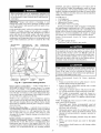
CONSIDERATIONS
its. If limits are exceeded, the units will automatically
lock the compressor out of operation. Manu_d reset will
IMPORTANT: Units have high ambient operating limbe required to restgu-tthe compressor.
Installation and selwicing of air-conditioning equipment can
be hazardous due to system pressure and electric_d components. Only trained and qualified service personnel should install, repaiL or service ai>conditioning equipment.
Untrained personnel can perform basic maintenance functions of cleaning coils and filters and replacing filters. All other
operations should be performed by trained service personnel.
When working on ai>conditioning equipment, observe
Manufacturer
If you cannot reach your gas supplier,
department.
reserves the right to discontinue, or change at any time, specifications
Catalog No. 04-53480009-01
Printed in U,S.A,
or designs
Form 48TJ-22SI
without notice and without incurring obligations.
Pg 1
3-06
Replaces:
48TJ-21SI
I
]
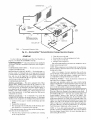
INSTALLATION
Step 2 --
Inspect unit for transportation dmnage. If &_mage is found,
file claim with transportation agency.
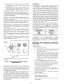
Step 1 --
Provide
Unit Support
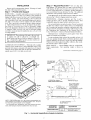
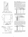
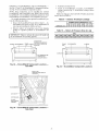
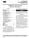
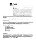
ROOF CURB -- Assemble and install accessory roof curb or
horizont_d a&tpter roof curb in accordance with instructions
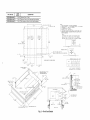
shipped with this accessory. See Fig. 1 and 2. Install insulation,
cant strips, roofing, and counter flashing as shown. Ductwork
can be installed to roof curb or horizontal adapter roof curb before unit is set in place. Curb or a&tpter roof curb should be
level. This is necessary to permit unit drain to function properly. Unit leveling tolerance is + l/l(_ in. per linear fl in any direction. Refer to Accessory Roof Curb or Horizontal A&_pter
Roof Curb Installation Instructions for additional information
as required. When accessory roof curb or horizontal adapter
roof curb is used, unit may be installed on class A, B, or C roof
covering material.
IMPORTANT: The gasketing of the unit to the roof curb
or adapter roof curb is critical for a watertight se_d.
Inst_fll gasket with the roof curb or adapter as shown in
Fig. 2. Improperly applied gasket can _dso result in air
leaks and poor unit performance.
ALTERNATE UNIT SUPPORT -- When the curb or adapter
cannot be used, install unit on a noncombustible
surface. Support unit with sleepers, using unit curb support area. If sleepers
cannot be used, support long sides of unit with a minimum of 3
equally spaced 4-in. x 4-in. pads on each side.
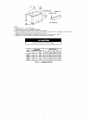
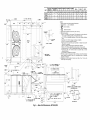
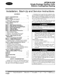
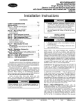
Rig and Place Unit --
Do not diop unit;
keep upright. Use spreader bras over unit to prevent sling or
cable &image. Rollers may be used to move unit across a roof.
Level by using unit frame as a refelence; leveling tolerance is
_+1/1_in. per linear fl in any direction. See Fig. 3 for additiomfl
information. Unit operating weight is shown in Table 1.
Four lifting holes are provided in ends of unit base rails as
shown in Fig. 3. Refer to rigging instructions on unit.
POSITIONINGMaintain
clearance, per Fig. 4 and 5,
around and above unit to provide minimum distance from
combustible materials, proper airflow, and service access.
Do not install unit in an indoor location. Do not locate unit
air inlets near exhaust vents or other sources of contmninated
all: For proper unit operation, adequate combustion and ventilation air must be provided in accordance with Section 5.3 (Air
for Combustion and Ventilation) of the National Fuel Gas
Code, ANSI Z223.1 (American National Stan&_rds Institute).
Although unit is weatherproof,
higher level runoff and overhangs.
guard against
water from
Ix)cate mechanical diaft system flue assembly at least 4 ft
from any opening through which combustion products could
enter the building, and at least 4 ft from any adjacent building.
When unit is located adjacent to public walkways, flue assembly must be at least 7 ft above grade.
ROOF MOUNT-bution requirements.
Table 1.
Check building codes for weight distriUnit operating weight is shown in
hlstructions
continued
on page 9.
25% VENT AIR//
ECONOMIZER
HOOD
BLOCK-OFFJ___
PAN
i
I
A,R
OUT
HORIZONTALSUPPLY/
CURB
TRANSITION
DUCT
(CRRFCURB013A00)
FULLY INSULATED
SUPPLY PLENUM
14-3/4_
1 1/2 # DENSITY,
STICK PINNED & GLUED
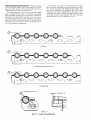
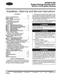
NOTE: CRRFCURB013A00
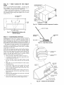
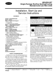
is a fully factory preassembled horizontal adapter and includes an insulated transition duct. The pressure drop through the adapter curb is negligible.
For horizontal return applications: The power exhaust and barometric relief dampers must be installed in the return air duct.
12" WIDE STANDING-SEAM PANELS
ACCESSORY
PACKAGE NO.
CRRFCURB013A00
Fig. 1 -- Horizontal Supply/Return
CURB
HEIGHT
1'-11"
(584
Adapter Installation
DESCRIPTION
Pre-Assembled, Roof Curb,
Horizontal Adapter
PKG. NO. REF.
DESCRIPTION
HEIGHT
CRRFCURBOIOAO0
1"- 2" (305)
Standard Curb 14" High
CRRFCURBO11AO0
2'- CURB
0" (610)
Standard Curb for Units Requiring
CRRFCURBO12AO0
2'- 0" (610)
Side Supply and Return Curb for High Installation
High Installation
S'-I0
I/2"
=I
PLAN
VIEW
NO-E5_
1, ROOF
CURB ACCESSORY
IS SHIPPED
DISASSEMBLED.
2. IN5ULATED
PANEL5_
1_ THICK
NEOPRENE
COATED
I-I/2 LS DENSITY
3. DIMEN51ON5
iN ( ) ARE
IN MILLIMETER5,
4. I:zZ_>DIRECTiON
OF AIR FLOW
5, ROOFCURB=
IS GA_
(VAO3-SS)
5TL,
6. A 90 DEGREE
ELBOW
MUST
BE
INBTALLEO
ON THE SUPPLY
DUCT
WORK
BELOW
THE UNIT
DIgCHARGE
FOR UNITS
EQUIPPED
WITH
ELECTRIC
HEATERS.
--OUTLINEGPUN,T
OF
ROOF
CURB
NOTE_
iBOHPRi
5UPPL
IBECT.
G'
(REF
SUPPLY
OPENING
CURB
2 3/1S _
(1SSS)
OPENING)
TO
PREVENT
BUILD-UP
IN
SECTION,
UNIT
5'-9"
(1753)
THE
THE
HAZARD
DRAIN
CAN
OF
PAN
ONL
V
STAGNANT
OF
THE
BE
i
AND
= CSMPRES50R
1
AS
SHOWN.
1
A_
)R
KEEP
POWER
_-o-s
(132)
THIS
AREA
(GAS
ENTRY
CLEAR
FOR
CONDENSER
FOR
GAS
(310)
DUCT
TO
I
ENSi
AND
FIR
D ROOFTOPS)
i
END
COMPRESSOR
J
B_L
3/s"
DIMEN51ON5
ATTACH
ROOF
(degPees
ond
ir/chetO
CURB
(578)
UNIT LEVELING
_Fro_ edge OF uniL
////_
TOLERANCES
to horizonLaL,
_NAIL
GASKET
HEIGHT
FROM TABLE
(Sl)
_
COUNTER
(FIELD
NOM, 514"
X
(S2)
X (102)
TYP.
4 PLCS
O'
WATER
INDOOR
PITCHED
ROOFING
FELT
(FIELD
SUPPLIED)
DUCT
1
(44)
(FIELD
j
FLASHING
SUPPLIED)
SUPPLIED)
CANT
(FIELD
5TRP
SUPPLIED)
(75)
UNIT
(FIELD SUPPLIED)
ROOFING MATERIAL
OPENINGS
O'-S
(421)
RETURN _
5'-7
1116"
(1703A
SUPPLY
_*_q(14s7I"-6 _ ,
_0"_2
I/2
(CRRFCURBOI2AO0
ONLY)
(64)
(CRRFCURSOI2AO0
AIR
RETUR i_ AIR
ONLY)
SECTION
Fig. 2 -- Roof Curb Details
A-A
OPTIONAL
=SIDE
SUPPLY
(FIELD
SUPPLIED)
I0'-0"
(3048)
,SPREADERBARS
"DETAIL
A"
3'-7 112"
(t t 05)
_
_RIGGINGHOOK
UNIT BASE RAIL
SEE
"DETAIL
A'
NOTES:
1. Dimensions in ( ) are in millimeters.
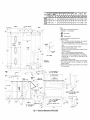
2. Refer to Fig. 4 and 5 for unit operating weights.
3. Remove boards at ends of unit and runners prior to rigging,
4. Rig by inserting hooks into unit base rails as shown. Use corner post from packaging
damage, Use bumper boards for spreader bars on all units.
5. Weights do not include optional economizer, Add 90 Ib (41 kg) for economizer weight,
6. Weights given are for aluminum evaporator and condenser coil plate fins.
All panels must be in place when rigging.
UNIT
48TJ
DIMENSIONS
MAXIMUM
SHIPPING
WEIGHT
A
B
Ib
kg
R-in.
mm
Ft-in.
mm
016
1775
805
6-111_
2121
3-5
1041
020
1875
850
6-111_
2121
3-3
024
1985
900
6-111_
2121
3-2
985
028
2135
988
6-111_
2121
3-2
985
Fig. 3 -- Rigging Details
991
to protect coil from
UNIT
STD UNIT
WEIGHT
Ib
kg
ECONOMIZER
WEIGHT
Ib
kg
CORNER
A
Ib
CORNER
B
kg
Ib
kg
CORNER
C
Ib
kg
48TJD,
TJF016
1650
748
90
41
423
192
386
175
403
183
48TJD,
TJF020
1800
816
90
41
432
196
410
186
461
209
CORNER
D
DIM A
DIM B
DIM C
kg
ft-in,
mm
if-in,
mm
ft-in,
mm
438
199
3-5
1041
3-5
1041
1-10
559
472
214
3-3
991
3-7
1092
1-8
508
Ib
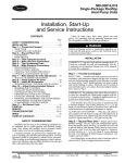
NOTES:
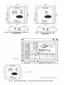
1. Refer to print for roof curb accessory dimensions.
2. Dimensions in ( ) are in millimeters.
3. _
4. E_
Center of Gravity.
Direction of airflow.
5. Ductwork to be attached to accessory roof curb only.
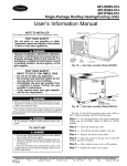
6. Minimum clearance:
• Rear: T-O" (2134) for coil removal. This dimension can be reduced to
4'-0" (1219) if conditions permit coil removal from the top.
• 4'-0" (1219) to combustible surfaces, all four sides (includes between
units).
• Left side: 4'-0" (1219) for proper condenser coil airflow.
• Front: 4'-0" (1219) for control box access.
• Right side: 4'-0" (1219) for proper operation of damper and power
exhaust if so equipped.
• Top: 6'-0" (1829) to assure proper condenser fan operation.
• Bottom: 14" (356) to combustible surfaces (when not using curb).
• Control box side: 3'-0" (914) to ungrounded surfaces, non-combustible.
• Control box side: 3"-6" (1067) to block or concrete walls, or other
grounded surfaces.
• Local codes or jurisdiction may prevail.
7. With the exception of clearance for the condenser coil and the damper/
power exhaust as stated in Note #6, a removable fence or barricade
requires no clearance.
8. Dimensions are from outside of corner post. Allow 0'-s/l_" (8) on each side
for top cover drip edge.
L_
_0"11
CORNER CS
3" S
iT6)
0
B
3 //8"_
t791
3/8"
OIA
CONCENTRIC
K.O.
(35)
TOP
LEFT
_5/I_CORNER
(3031
r[LTERS
ACCESSFAR S]OE
SIDE
3 9
(lt43}
VIEW
Z-Z
BAROMETRIC RELIEF/POWER
(ACCESSORY ONLY)
iS1)
FRONT
SECTION
Fig. 4-
Base Unit Dimensions; 48TJ016,020
A+A
EXHAUST
UNIT
BTD UNIT
WEIGHT
Ib
kg
ECONOMIZER
WEIGHT
Ib
kg
CORNER
A
Ib
kg
CORNER
B
Ib
kg
CORNER
C
Ib
kg
48TJD,
TJF024
1850
839
90
41
443
201
406
184
476
216
48TJ D,
TJF028
2000
907
90
41
471
214
428
194
526
239
CORNER
D
DIM A
DIM B
DIM C
kg
ft-in,
mm ft-in,
mm
ft-in,
mm
525
238
3-2
965
3-5
1041
1-8
508
574
260
3-2
965
3-8
1041
1-8
508
Ib
NOTES:
1. Refer to print for roof curb accessory dimensions.
2. Dimensions in ( ) are in millimeters•
3. _
TYPICAL
4 CORNERS
Center of Gravity.
4. E_
Direction of airflow•
5. Ductwork to be attached to accessory roof curb only.
6. Minimum clearance:
• Rear: 7'-0" (2134) for coil removal• This dimension can be reduced to
4'-0" (1219) if conditions permit coil removal from the top.
• 4'-0" (1219) to combustible surfaces, all four sides (includes between
units).
• Left side: 4'-0" (1219) for proper condenser coil airflow.
• Front: 4'-0" (1219) for control box access•
• Right side: 4'-0" (1219) for proper operation of damper and power
exhaust if so equipped.
• Top: 6"-0" (1829) to assure proper condenser fan operation•
• Bottom: 14" (356) to combustible surfaces (when not using curb).
• Control box side: 3'-0 _"(914) to ungrounded surfaces, non-combustible.
• Control box side: 3'-6" (1067) to block or concrete walls, or other
grounded surfaces•
• Local codes or jurisdiction may prevail•
7. With the exception of clearance for the condenser coil and the damper/
power exhaust as stated in Note #6, a removable fence or barricade
requires no clearance•
8. Dimensions are from outside of corner post. Allow O'-S/16" (8) on each
side for top cover drip edge.
1
OIA
I-_o, 11 lJ,,o
13031
L£rT
3'11
t12002
HOLE
COHRER
6
(20Z)_
trg2
SIDE
1/4'
( 51 I
SECTION
Fig. 5 -- Base Unit Dimensions; 48TJ024,028
A-A
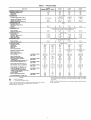
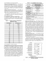
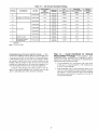
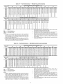
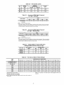
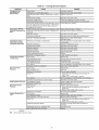
Table 1 -- Physical Data
016D/F
UNIT 48TJ
208/230, 460 v I
15
1650
90
200
NOMINAL CAPACITY (tons)
OPERATING WEIGHT (Ib)
Economizer
Roof Curb
COMPRESSOR
Quantity,.,Model
(Ckt 1, Ckt 2)
Number of Refrigerant
Circuits
Oil (oz) (Ckt 1, Ckt 2)
Stages of Capacity Control (%)
REFRIGERANT TYPE
Expansion Device
Operating Charge (Ib-oz)
10-5
COIL
20
1850
90
200
25
2000
90
200
1...SM120,
1 ._SM110
2
110,110
52/48
1...SM161,
1 _.SM120
2
112, 110
56/44
11-5
2...17
21.7
16-3 I
21-0
14-8
3_.15
I
3...15
21.7
21.7
Propeller Type
10,400
9300
13,700
3...22
3..,22
2...30
V2...1050
V2._1050
1 ..,1075
1100
1100
3400
Cross-Hatched 3/8-in. Copper Tubes, Aluminum
Copper Plate Fins, Face Split
Rows...Fins/in.
Total Face Area (sq ft)
EVAPORATOR FAN
Quantity...Size (in.)
Type Drive
Nominal Cfm
Motor Hp
Motor Nominal Rpm
Low-Medium
High Static
Motor Bearing Type
Maximum Allowable Rpm
Motor Pulley Pitch Diameter
Min/Max (in.)
Nominal Motor Shaft Diameter (in.)
Fan Pulley Pitch Diameter (in,)
Nominal Fan Shaft Diameter
Belt, Quantity...Type...Length
I
17.5
2...17
Maximum Continuous Bhp
Motor Frame Size
Nominal Rpm High/Low
Fan r/s Range
(in,)
(in.)
Pulley Center Line Distance (in.)
Speed Change per Full Turn of
Movable Pulley Flange (rpm)
Movable Pulley Maximum Full Turns
From Closed Position
Factory Speed
Factory Speed Setting (rpm)
at Pulled/lin.t
Static
Low-Medium
High Static
Static
Low-Medium
High Static
Static
Low-Medium
High Static
Static
Low-Medium
High Static
Static
Low-Medium
High Static
Static
I
2,..10 x 10
Belt
6000
3.7
1725
2,.,10 x 10
Belt
6000
3,0
1725
4.25
3,45
56H
56H
891-1179
1227-1550
Ball
1550
3.1/4.1
3.7/4.7
7/8
6.0
5.2
13/16
1 ,..BX_,42
1 ,..BX_,42
13.5-15.5
48
55
1159-1429
5
3.5
1035
1389
13/16
LEGEND
---
18
1800
90
200
15-4
Cross-Hatched 3/8-in. Copper Tubes, Aluminum Lanced,
Aluminum Pre-Coated, or Copper Plate Fins
Rows...Fins/in.
Total
Face Area (sq ft)
CONDENSER FAN
Nominal Cfm
Quantity,..Diameter
(in.)
Motor Hp...Rpm
Watts Input (Total)
EVAPORATOR COIL
Bhp
TXV
028D/F
10-13 I 15-2I
2
Fan Shaft Diameter
024D/F
Scroll
1 ...SM120,
1_.SR*782AE
2
110, 72
60/40
R-22
TXV
2_.SR*942AE
2
90, 90
50/50
c,rcu,t,*
Circuit
CONDENSER
020D/F
575 v
Brake Horsepower
Thermostatic Expansion Valve
*Circuit 1 uses the lower portion of condenser coil and lower portion of evaporator coils; and Circuit 2 uses the upper portion of both coils.
tRollout switch is manual reset.
Ball
1550
4.3/5,3
7&
6,4
13/16
1,..BX..,45
13.5-15.5
44
5
3.5
1296
-13/16
17.5
17.5
3...15
I
3_.15
Centrifugal Type
2...12 x 12
2...12 x 12
Belt
Belt
7200
8000
5
7.5
1745
1745
8.7 [208/230,575
5.90
9.5 [460 v]
184T
213T
910-1095
1069-1287
Ball
1550
4.9/5.9
4.9/5.9
1V8
9,4
8,0
17/16
1.-BX,..50
1.-BX-.48
13.3-14.8
37
34
5
3.5
1002
1178
17/16
I
4...15
21.7
12,500
2...30
1 .,.1075
3400
Lanced or
I
v]
17.5
4_.15
2._12x12
Belt
10,000
10
1740
10.2 [208/230, 575 v]
11,8 [460 v]
215T
1002-1225
1193-1458
Ball
1550
5,4/6,6
5,4/6,6
13/8
9.4
7.9
17/16
1-.BX-.54
1 ...BX-.50
14.6-15,4
37
44
1066-1283
1332-1550
Ball
1550
4,9/5.9
4,9/5.9
lS/s
8.0
6,4
17/16
2..,BX,..50
2..,BX,..47
14.6-15,4
36
45
5
3.5
1120
1328
5
3.5
1182
1470
17/16
17/16
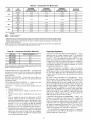
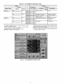
**The 48TJ028 units requires 2-in. industrial-grade filters capable of handling
face velocities of up to 625 ft/min (such as American Air Filter no. 5700 or
equivalent).
NOTE: The 48TJ016-028
on the suction side.
units have a low-pressure
switch (standard)
located
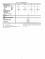
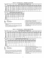
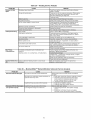
Table 1 -- Physical Data (cont)
UNIT 48TJ
FURNACE SECTION
Rollout Switch Cutout Temp (F)t
Burner Orifice Diameter (in....drill size)
Natural Gas
Thermostat Heat Anticipator Setting (amps)
208/230, 575
Stage 1
Stage 2
460 v
Stage 1
Stage 2
Gas Input
Stage 1
Stage 2
Efficiency (Steady State) (%)
Temperature Rise Range
Manifold Pressure (in. wg)
Natural Gas
Gas Valve Quantity
Field Gas Connection Size (in.-FPT)
HIGH-PRESSURE
SWITCH (psig)
Cutout
Reset (Auto)
LOW-PRESSURE SWITCH (psig)
Cutout
Reset (Auto)
FREEZE PROTECTION THERMOSTAT
Opens
Closes
OUTDOOR-AIR
INLET SCREENS
Quantity...Size (in.)
016D/F
O20D/F
024D/F
028D/F
190
190
190
190
0.1285-.30/0.136-.29
0.1285.-30/0.136-.29
0.98
0.44
0.80
0.44
172,000/225,000
230,000/300,000
81
15-45/20-50
3/4
---
206,000/270,000
275,000/360,000
81
15-45/20-50
3.3
1
3/4
0.1285_.30/0.136...29
0.98
0.44
0.80
0.44
206,000/270,000
275,000/360,000
81
15-45/20-50
3.3
1
3/4
426
32O
27
44
(F)
3O-+5
45-+5
Cleanable
2...20 x 25 x 1
1...20 x 20 x 1
Throwaway**
4_.20 x 20 x 2
4...16 x 20 x 2
V2 Hp, 208/230-460
LEGEND
Bhp
TXV
0.98
0.44
0.80
0.44
206,000/270,000
275,000/360,000
81
15-45/20-50
3.3
1
3/4
3.3
1
RETURN-AIR FILTERS
Quantity.,.Size
(in.)
POWER EXHAUST
0.1285.-30/0.136-.29
0.98
0.44
0.80
0.44
Brake Horsepower
Thermostatic Expansion Valve
*Circuit 1 uses the lower portion of condenser coil and lower portion of evaporator coils; and Circuit 2 uses the upper portion of both coils.
tRollout switch is manual reset.
v Motor Direct Drive, Propeller-Fan
(Factory-Wired
for 460 v)
**The 48TJ028 units requires 2-in. industrial-grade
filters capable of handling
face velocities of up to 625 ft/min (such as American Air Filter no. 5700 or
equivalent).
NOTE: The 48TJ016-028
on the suction side.
units have a low-pressure
switch (standard)
located
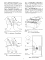
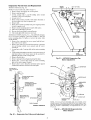
Step 3 --
Field Fabricate Ductwork -- Secure all
ducts to building structure. Use flexible duct connectors between unit and ducts as required. Insulate and weatherproof all
external ductwork, joints, and roof openings with counter
flashing and mastic in accordance with applicable codes.
Ducts passing through an unconditioned
sulated and covered with a vapor barrie];
Step 4 --
space must be in-
and
roof
CUlb
Install Flue Hood and Wind
--
Unit
basepans.
HEAT
Baffle --
Flue hood and wind baffle are shipped secured under main
control box. To install, secure flue hood to access panel. See
Fig. 9. The wind baffle is then installed over the flue hood.
NOTE: When properly installed, flue hood will line up with
combustion fan housing. See Fig. 10.
Step 6 -- Trap Condensate
Make Unit Duct Connections
is shipped for thru-the-bottonl duct connections. Ductwork
openings are shown in Fig. 1, 4, and 5. Duct connections are
shown in Fig. 6. Field-fabricated
concentric ductwork may be
connected as shown in Fig. 7 and 8. Attach all ductwork to roof
curb
Step 5 --
Drain -- See Fig,
11
for drain location. One 3/4-in. half coupling is provided inside
unit evaporator section for condensate drain connection. An
81/2-in. x 3/4-in. diameter and 2-in. x 3/4-in. diameter pipe nipple, coupled to standard 3/4-in. diameter elbows, provide a
straight path down through hole in unit base rails (see Fig. 12).
A trap at least 4-in. deep must be used.
I'-O1
24"MIN.
SEE NOTE
/
BAFFLE
[_AIR
OUT
NOTE: Do not drill in this area; damage to basepan may result in
water leak.
Fig. 6 -- Air
Distribution
NOTE: Dimensions A, A', and B' are obtained from field-supplied
ceiling diffuser.
Shaded area indicates block-off panels.
Fig. 8-
Concentric
Duct Details
-- Thru-the-Bottom
/
/
\
ii
,.ii
\
/
\
J
\
/
\
N
WIND
BAFFLE
\
\
\
FLUE
SEE NOTE
\
HOOD
NOTE
COMBUSTION
FAN HOUSING
(INSIDE)
AIR OUT
AIR IN
AIR OUT
NOTE: Do not drill in this area; damage to basepan may result in
water leak.
Fig. 7 -- Concentric
[l
[l
[
[
[
[
[
[
[
Duct
WIND BAFFLE
MOUNTING HOLES
Air Distribution
Fig. 9 -- Flue Hood Location
INDUCED
MOTOR
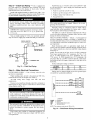
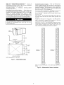
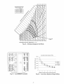
Step 7 -- Orifice Change -- This unit is factory assembled for heating operation using natund gas at an elevation
DRAFT
from sea level to 2000 ft. This unit uses orifice type
LH32RFnnn, where "nnn" indicates the orifice size based on
drill size diameter in thousands of an inch.
HIGH ELEVATION (Above 2000 ft) -- Use accessory high
altitude kit when inst_dling this unit at an elewttion of 2000 to
7000 ft. For elevations above 7000 ft, refer to Table 2 to identify the correct orifice size for the elevation. See Table 3 for the
number of orifices requiled for each unit size. Purchase these
orifices from your local Carrier dealel: Follow instructions in
accessory Installation Instructions to install the correct orifices.
Table
2 -- Altitude
ELEVATION (ft)
COMBUSTION
FAN HOUSING
Fig. 10-
MAIN BURNER
SECTION
Combustion
0-1,999
2,000
3,000
4,000
5,000
6,000
7,000
8,000
9,000
10,000
HEAT EXCHANGER
SECTION
Fan Housing Location
Compensation*
NATURAL
GAS ORIFICE]-
Low Heat
30
30
31
31
31
31
32
32
33
35
High Heat
29
29
30
30
30
30
31
31
31
32
*As the height above sea level increases, there is less oxygen per
cubic foot of air. Therefore, heat input rate should be reduced at
higher altitudes. Includes a 4% input reduction per each 1000 ft.
1-Orifices available through your Carrier dealer.
Table 3 -- Orifice Quantity
UNIT
3/4" FPT DRAIN
CONNECTION
ORIFICE QUANTITY
48TJD016
5
48TJD020,
48TJD024,
48TJD028,
48TJF016
6
48TJF020,
48TJF024,
48TJF028
7
CONVERSION
TO LP (Liquid Propane) GAS -- Use accessory LP gas conversion kit when converting this unit for use
with LP fuel usage for elevations up to 7000 ft. For elevations
above 7000 ft, refer to Table 4 to identify the correct orifice
size for the elewttion. See Table 3 for the number of orifices
required for each unit size. Purchase these orifices from your
loc_fl Carrier dealel: Follow instructions in accessory Installation Instructions to inst_dl the correct orifices.
1-3/8"
DRAIN HOLE
Fig. 11 -- Condensate Drain Details
(48TJ016 Shown)
Table 4 -- LP Gas Conversion*
ELEVATION (ft)
0-1,999
2,000
3,000
4,000
5,000
6,000
7,000
8,000
0,000
10,000
3/4 -IN. FPT
DRAIN CONNECTION
____.
(FIELD-SUPPLIED)NIPPLE
(HALF CO_--
3"
BASE RAIL _@_
8 1/2-1N. (FIELD ....
SUPPLIED) NIPPLE
Fig. 12-
Condensate
LP GAS ORIFICE]"
36
37
38
38
39
40
41
41
42
43
*As the height above sea level increases, there is less oxygen per
cubic foot of air. Therefore, heat input rate should be reduced at
higher altitudes. Includes a 4% input reduction per each 1000 ft.
1-Orifices available through your Carrier dealer.
Drain Piping Details
10
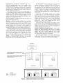
Tlansformer no. 1 is wired for 230-v unit. If 208/230-v unit
is to be run with 208-v power supply, the transformer must be
rewired as follows:
Step 8 --
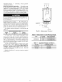
Install Gas Piping -- Unit is equipped for
use with natured gas. Installation must conform with loc_d
building codes or. in the absence of loc_d codes, with the
National Fuel Gas Code, ANSI Z223.1.
1. Remove
Install field-supplied manu_d gas shutoff valve with a lh-in.
NPT pressme tap for test gage connection at unit. Field gas piping must include sediment trap and union. See Fig. 13.
Do not pressure test gas supply while connected to unit.
Always disconnect union before servicing. Exceeding
maximum manifold pressure may cause explosion and
injury.
I
FIELD CONTROL WIRING -- Install a Carrier-approved
accessory thermostat assembly according to installation instructions included with accessory. Ix)cate thermostat assembly
on a solid interior wall in the conditioned space to sense average temperature.
FT'I
GAS
Route thermostat
cable or equivalent
single leads of
colored wire from subbase termimds through conduit in unit to
low-voltage connections as shown on unit label wiring diagram
and in Fig. 15.
PRESSURE TAP
(1/8" NPT PLUG)
NOTE: For wire runs up to 50 ft, use no. 18 AWG (American
Wire Gage) insulated wire (35 C minimum). For 50 to 75 ft,
use no. 16 AWG insulated wire (35 C minimum). For over
75 ft, use no. 14 AWG insulated wire (35 C minimum). All
wire larger than no. 18 AWG cannot be directly connected at
the thermostat and will require a junction box and splice at the
thermostat.
_
o&
Recap both wires.
Unit failure as a result of operation on improper line voltage
or excessive phase imbalance constitutes abuse and may cause
&Lmage to electrical components.
MANUAL SHUTOFF
UNIT
4.
Operating voltage to compressor
must be within voltage
range indicated on unit nameplate. On 3-phase units, voltages
between phases must be balanced within 2%.
Size gas-supply piping for 0.5-in. wg maximum pressure
drop. Do not use supply pipe sm_dler than unit gas connection.
_
Remove cap from orange (230 v) spliced wire.
Replace orange wire with led wire.
Be certain unused wires ale capped. Failure to do so may
&_mage the transformers.
tion must not be less than 5.5 in. wg or greater than
IMPORTANT:
Natural gas pressure at unit gas connec13.5 in. wg.
(FIELD SUPPLIED)
_ _
cap fiom red (208 v) wire.
2.
3.
•---- SEDIMENTTRAP
Set heat anticipator settings as follows:
Fig. 13 -- Field Gas Piping
Step 9 --
Make Electrical
Connections
wiring
must
comply
with
NEC
and
W1
W2
0.98
0.80
0.44
0.44
Settings may be changed slightly to provide a greater degree
of comfort for a particuku installation.
FIELD POWER SUPPLYUnit is factory wiled for voltage shown on nameplate.
When inst_dling units, provide a disconnect per NEC (National Electrical Code) of adequate size (Table 5).
All field
requirements.
VO LTAG E
208/230,575
460
----1
TBI
II
local
FIELD
i_II
III
I
III
=U.l
z
II_
POWER
[
Route power ground lines through control box end panel or
unit basepan (see Fig. 4 and 5) to connections as shown on unit
wiring diagram and Fig. 14.
i _
.......
I _
SUP_PLY
z
i
I-IN
The correct power phasing is critical in the operation of the
scroll compressol,s. An incorrect phasing will cause the
compressor to rotate in the wrong direction. This may lead
to premature compressor failure.
l
EQUIP
I
..............
EQUIP
GND
NEC
TB
The unit must be electrically grounded in accor&mce with
local codes and NEC ANSI/NFPA 70 (National Fire Protection Association)
to protect against fire and electric
shock.
GND
]
-----
LEGEND
Equipment
Ground
National Electrical Code
Terminal Block
NOTE: The maximum wire size for TB1 is 2/0.
Fig. 14-
Field wiring must confirm to temperature limitations for
type "T" wire. All field wiring must comply with NEC and local requirements.
11
Field
Power
Wiring
Connections
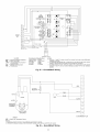
OPTIONAL NON-FUSED
DISCONNECT
-- On units with
the optiomfl non-fused disconnect, incoming power will be
wired into the disconnect switch. Refer to Fig. 16 for wiring
for 100 and 200 amp disconnect
switches. Units with an
MOCP under 100 will use the 100 amp disconnect switch.
Units with an MOCP over 100 will use the 200 amp disconnect switch. Refer to the applicable disconnect wMng diagram.
THERMOSTAT
Lu
cc
To prevent breakage during shipping, the disconnect handle
and shaft are shipped and packaged inside the unit control box.
Install the disconnect handle before unit operation. To install
the handle and shaft, perform the following procedure:
1. Open the control box door and remove the handle and
shaft from shipping location.
2. Ix_osen the Allen bolt located on the disconnect switch.
The bolt is located on the square hole and is used to hold
the shaft in place. The shaft cannot be inserted until the
Allen bolt is moved.
3.
Tighten the Allen bolt to lock the shaft into position.
Close the control box dool:
6.
Attach the handle to the external access door with the two
screws provided. When the handle is in the ON position,
the handle will be vertical. When the handle is in the OFF
position, the handle will be horizontal.
7.
Turn the handle to the OFF position and close the dool:
The handle should fit over the end of the shaft when the
door is closed.
8.
The handle must be in the OFF position to open the control box dool:
z
a_
cc
o
_
o
_
Z
_,
m
I
cc
m
Z
Fig. 15 -- Field Control Thermostat Wiring
UNIT
lO0
BLK,
WIRING
YEL.
6T3
4T2
2T1
LOAD
3L2
1L1 LINE
BLU.
I
AMP
[ NON_:EPDOWDEIRsCONNE_T
_--
I
Insert the disconnect shaft into the squae hole on the disconnect switch. The end of the shaft is specially cut and
the shaft can only be inserted in the correct orientation.
4.
5.
q
m
ASSEMBLY
_
_
OA:
'
;_ ;__T2E
j
FIELD
POWER SUPPLY
UNIT
200
BLK.
AMP
5L3
WIRING
YEL.
BLU,
4--+--t--- '
[ NON FUSED DISCONNECT
__i
FIELD
_i_
POWER
Lli E j
SUPPLY
NOTE: The disconnect takes the place of TB-1 as shown on the unit wiring
diagram label and the component arrangement label.
Fig. 16-
OPTIONAL
CONVENIENCE
OUTLET-On units with
optiomfl convenience
outlet, a 115-v GFI (ground fault interrupt) convenience outlet receptacle is provided for field wiring.
Field wiring should be run through the 7Is-in. knockout provided in the basepan near the return air opening.
12
Optional
Non-Fused
Disconnect
Wiring
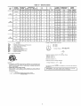
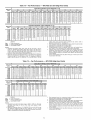
Table 5 -- Electrical Data
NOMINAL
VOLTAGE
UNIT
48TJ
(3Ph,
60Hz)
208/230
016
(15 Tons)
RLA
LRA
RLA
LRA
Q_
Hp
FLA(ea)
190
3
0.5
1.7
3.7
460
414
508
13.5
95
13.5
95
3
0.5
0.8
3.7
4.8
575
518
632
10.2
75
10.2
75
3
0.5
0.8
3.0
3.9
187
253
33
237
23
184
3
0.5
1.7
5.0
15.8/15.8
460
414
508
16.2
130
10.2
90
3
0.5
0.8
5.0
7.9
575
518
632
12.7
9
73
3
0.5
0.8
5.0
6.0
187
253
33
460
414
508
575
518
46O
85
10.5/11.0
237
29.5
237
2
1
6.6
7.5
16.2
130
14.1
130
2
1
3.3
7.5
13.0
632
12.7
85
11.3
85
2
1
3.4
7.5
10.0
187
253
47.5
265
33
237
2
1
6.6
10.0
414
508
22.9
145
16.2
130
2
1
3.3
10.0
518
632
17.9
102
12.7
85
2
1
3.4
25.0/25.0
28.0/28.0
COMBUSTION
FAN MOTOR
10.0
13.0
POWER
SUPPLY
LRA
FLA
MCA
MOCP*
4.6
18.8
0.57
0.57
74/74
79/79
90/90
100/100
2.3
6.0
0.30
0.30
38
40
50
50
2.1
4.8
0.57
0.57
30
32
35
40
4.6
18.8
0.87
0.57
88/88
90/90
110/110
110/110
2.3
6.0
0,30
0.30
41
43
80
50
2.1
4.8
0,87
0.57
33
35
45
45
4.6
18.8
0.57
0.57
109/109
114/114
125/125
125/125
2.3
6.0
0.30
0.30
54
56
70
70
2.1
4.8
0.57
0.57
44
46
80
50
0.87
0.57
134/134
138/138
178/175
175/175
4.6
18.8
0,30
66
80
2.3
6.0
0.30
0.57
68
55
90
70
2.1
4.8
0.57
57
70
14.6
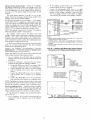
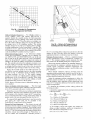
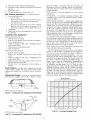
Example: Supply voltage is 460-3-60.
Full Load Amps
Heating, Air Conditioning and Refrigeration
Indoor (Evaporator) Fan Motor
Locked Rotor Amps
Minimum Circuit Amps
Maximum Overcurrent Protection
National Electrical Code
Outdoor (Condenser) Fan Motor
Rated Load Amps
A
B
C
(_
AB = 452 v
BC = 464 v
482 + 464 + 488
3
Average Voltage
AC = 455 v
1371
=--
*Fuse or HACR circuit breaker.
Determine
(AB) 487
(BC) 464
(AC) 487
Maximum
cCt os
3
= 457
maximum deviation from average voltage.
- 482 = 8 v
- 487 = 7 v
- 488 = 2 v
deviation is 7 v.
Determine
percent of voltage imbalance.
7
% Voltage Imbalance = 100 x
487
NOTES:
1. In compliance with NEC requirements for multimotor and combination load
equipment (refer to NEC Articles 430 and 440), the overcurrent protective
device for the unit shall be fuse or HACR breaker. Canadian units may be
fuse or circuit breaker.
2. Unbalanced 3-Phase Supply Voltage
Never operate a motor where, a phase imbalance in supply voltage is
o
greater than 2_,
Use the following formula to determine the percent of voltage imbalance,
% Voltage Imbalance
= 100 x
FLA
25.6
LEGEND
----------
FLA
Hp
190
575
FLA
HACR
IFM
LRA
MCA
MOCP
NEC
OFM
RLA
POWER
EXHAUST
IFM
25.6
208/230
028
(28 Tons)
Max
OFM
253
208/230
O24
(20 Tons)
Min
COMPRESSOR
No. 1
No, 2
187
208/230
020
(18 Tons)
VOLTAGE
RANGE
= 1.53%
This amount of phase imbalance
allowable 2%.
I
max voltage deviation from average voltage
average voltage
13
is satisfactory
as it is below the maximum
2%,
contact your Iflocal
utility company
immediately.is more than
IMPORTANT:
the electric
supply voltage
phase imbalance
II
Step 10 -ments
Make
Outdoor-Air
Inlet
AdjustOUTDOOR-AIR
HOOD AND
MOUNTING BRACKETS
MANUAL OUTDOOR-AIR
DAMPER -- All units (except
those equipped with a factory-inst_dled economizer)
have a
manual outdoor-air &tmper to provide ventilation ail:
Damper can be preset to admit up to 25% outdoor air into
return-tdr compartment. To adjust, loosen secunng screws and
move &tmper to desired setting, then retighten screws to secure
dmnper (see Fig. 17).
25% ADJUSTABLE
AIR DAMPER
/
F[_ER
PACKAGEAN[
HOOD
COMPONENTS
ol
/I
\
÷I
o
/
BASE
UNIT
/
RETURN-AIRFILTE}
ACCESS PANEL
Fig. 18-
g
Outdoor-Air
Hood Component Location
PANEL
SECURING
SCREWS
Fig. 17 -- Standard 25% Outdoor-Air
Section Details
UPPER
RETAINER
Step 11 -- Install Outdoor-Air
IMPORTANT:
If the unit is equipped with the optional
EconoMiSerIV.
move the outdoor air temperature sensor
prior to installing the outdoor air hood. See the Optional
EconoMiSerIV and EconoMiSer2 section for more details.
I
I
SEAL;
Fig. 19-
The outdoor- air hood is common to 25% air ventilation and
economizel: If EconoMiSerIV
is used, all electrical connections have been made and adjusted at the factoly. Assemble
and install hood in the field.
3.
4.
5.
6.
7.
8.
Seal
Strip
Location
BAFFLE
/
NOTE: The hood top panel, upper and lower filter retainel_,
hood drain pan, baffle (size 024 and 028), and filter support
bracket me secured opposite the condenser end of the unit. The
screens, hood side panels, remaining section of tilter support
bracket, seal strip, and hmdware are in a package located
inside the return-air filter access panel (Fig. 18).
1. Attach seal strip to upper filter retainer. See Fig. 19.
2.
PAN
Hood
\
LOWER
FILTER
RETAINER
Assemble hood top panel, side panels, upper filter retainel: and dnun pan (see Fig. 20).
Secure lower filter rettuner and support bracket to unit.
See Fig. 20. Leave screws loose on size 024 and 028
units.
Slide bafile (size 024 and 028) behind lower filter retainer
and tighten screws.
Ix_osen sheet metal screws for top panel of base unit
located above outdoor-air
inlet opening, and remove
screws for hood side panels located on the sides of the
outdoor-air inlet opening.
Match notches in hood top panel to unit top panel screws.
|nsert hood flange between top panel fange and unit.
Tighten screws.
Hold hood side panel flanges flat against unit, and install
screws removed in Step 5.
HOOD SIDE
PANELS (2)
BAFFLE
. (024 TO
028 ONLY)
LOWER
FILTER
RETAINER
FILTER SUPPORT
BRACKET
Insert outdoor-air inlet screens and spacer in channel created by lower filter retainer and filter support bracket.
HOOD DRAIN PAN
UPPER FILTER RETAINER
Fig. 20 -- Outdoor-Air
14
Hood
Details
Step 12 -- Install All Accessories--
Install all
Install Motormaster
[ Controls -- Only one Motormaster
I
control is required per unit. The Motormaster I control must be
used in conjunction with the Accessory 0 ° F Ix_w Ambient Kit
(purchased separately). The Motormaster [ device controls outdoor fan no. 1 while outdoor fans no. 2 and 3 are sequenced off
by the Accessory 0 ° F Low Ambient Kit.
Accessoiw 0 ° F Din' Ambient Kit -- Inst_dl the Accessory 0° F
Ix_w Ambient Kit per instruction supplied with accessory.
Sensor Assembly -- Install the sensor assembly in the location
shown in Fig. 25_
Motor MountTo ensure proper fan height, replace the existing motor mount with the new motor mount provided with
accessory.
Tran._fiwmer (460 and 575-v Units On@) -- On 460 and 575-v
units, a transhmner
is required. The transformer is provided
with the accessory and must be field-installed.
Motormaswr I Control -- Recommended
mounting location is
on the inside of the panel to the left of the control box. The
control should be mounted on the inside of the panel, vertically, with leads protruding from bottom of extrusion.
field-installed accessories. Refer to the accessoly installation
instructions included with each accessory.
MOTORMASTER®
I
CONTROL
INSTALLATION
(48TJ016,020
UNITS)
Install Field-Fabricated
Wind Baffles -- Wind baffles must
be field-fabricated for all units to ensure proper cooling cycle
operation at low ambient temperatures. See Fig. 21 for baffle
details. Use 20-gage,
galvanized
sheet metal, or similar
conosion-resistant
metal for baffles. Use field-supplied screws
to attach baffles to unit. Screws should be 1/4-in. diameter and
5/8-in. long. Drill required screw holes for mounting baffles.
To avoid dmnage to the refiigemnt coils and electric_d components, use recommended
screw sizes only. Use care
when drilling holes.
m
_Oo
_:tOo
°
_:toO°
_:to
°
_o°
_:_o
°
_o°
_o°
_o
_o
_o
_o
_o
_o
) MIN
BAFFLE TOP VIEW
1" (25) MIN--_
78.12" -+0.125"
0984 -+3)
I
10" (254)
_..]--" _¥p)
-'
40"
1016
_10"
+"--
.j
\
3/4"(19)0-¥P)--'_
=
ffYP)
""-'--I
_"_
15" (381)
1_
-4i----,i
SENSOR
LOCATION
(254)
(TYP)
"1" (25) MIN
_$o
°
_o°
_o°
_:to
°
€:to°
_o°
_1_o
o°
_:_o
°
BAFFLE FRONT VIEW
NOTE: Dimensions
_o
_o
SENSOR
LOCATION
_
,_
o
_
o
_o
_o
_o
in ( ) are in mm.
_o°
_oOO
°
Fig. 21 -- Wind Baffle Details
HAIRPIN
END
48TJ016
_o°
HAIRPIN
END
48TJ020
NOTE: All sensors are located on the eighth hairpin up from the
bottom.
Fig. 22 -- Motormaster
15
I Sensor Locations
MOTORMASTER®
V
CONTROL
INSTALLATION
(48TJ024,028
UNITS)
Install Field-Fabricated
Wind Baflles -- Wind baflles must
be field-fabricated for all units to ensure proper cooling cycle
operation at low ambient temperatures. See Fig. 21 for baflle
details. Use 20-gage, galvanized sheet metal, or similar corrosion-resistant metal for baffles. Use field-supplied screws to attach baffles to unit. Screws should be l/4-in, diameter and
5/8-in. long. Drill required screw holes for mounting baffles.
FROM FUSE BLOCK
10 o---1
>-
u
ca
1.2
1.3
o
o
To avoid dmnage to the refligerant coils and electrical components, use lecommended
screw sizes only. Use cme
when &'illing holes.
B
13B
Install Motormaster
V Controls
-The Motormaster
V
(MMV) control is a motor speed control device which adjusts
condenser fan motor speed in response to declining liquid lefrigerant pressure. A properly applied Motormaster V control
extends the operating range of air-conditioning
systems and
permits operation at lower outdoor ambient temperatures.
The minimum
operate are:
mnbient temperatures
Unit
40
ooo
o
at which the unit will
TO MOTOR(S)
TEMPERATURE
Standard
o
TO PRESSURE
TRANSDUCER
OPERATING
Unit with
Low Ambient
25
Kit
Fig. 23 -- Motormaster
LIMITS -- F°
I
Unit with
I
MMV -20
Control
V Control
Table 6 -- Motormaster V Control Package Usage
To operate down to the ambient
temperatures
listed,
Motormaster V controls (Fig. 23) must be added. Field-fabricated and installed wind baffles gue _dso required for _dl units (see
Fig. 21). The Motormaster V control permits operation of the
unit to an ambient temperature of-20 IF.The control regulates the
speed of 3-phase fan motors that gue compatible with the control.
These motors me factory installed.
ITEM DESCRIPTION
48TJ024,028
UNIT
V control
per instructions
CRLOWAMB015A00
460
VOLTAGE
575
CR LOWAMB016A00
Table 7 -- Applicable
See Table 6 for the Motormaster V control accessory package usage. Table 7 shows applicable voltages and motors.
Replacement of motor or fan blade IS NOT REQUIRED
ON
CURRENT
PRODUCTION
UNITS since the control is
compatible with the factory-installed
fan motors. Only field
wiring control is required.
Inst_dl the Motormaster
with accessory.
I
208/230
VOLTAGE
208/230-3-60
480-3-60
575-3-60
supplied
16
CRLOWAMB017A00
Voltages
and Motors
COMPATIBLE MOTOR
HD52AK654
HD52AK654
HD52GE576
Step 13 --Adjust
Factory-Installed
Options
into the fan section, down along the back side of the fan, and
_dong the fan deck over to the supply-air opening.
The SAT probe is wire-tied to the supply-air opening (on the
horizontal opening end) in its shipping position. Remove the
sensor for installation. Re-position the sensor in the flange of
the supply-air opening or in the supply air duct (as required by
local codes). Drill or punch a l/2-in, hole in the flange or duct.
Use two field-supplied, self-drilling screws to secme the sensor
probe in a horizontal orientation.
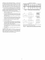
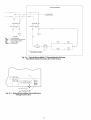
PREMIERLINK
TM CONTROL
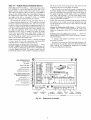
-- The PrelnierLink controller is available as a special order from the facto U and is compatible with the Ctmier Comfort Network® (CCN) system.
This control is designed to allow usel_ the access and ability to
change factoly-defined
settings, thus expanding the function of
the standard unit control board. Carrier's diagnostic stan&ud
tier display tools such as Navigator r_'_ device or Scrolling
Marquee can be used with the PremierLink controller.
The PremierLink controller (see Fig. 24) requires the use of
a C;urier electronic themiostat or a CCN connection for time
broadcast to initiate its internal timeclock. This is necessmy for
broadcast of time of day functions (occupied/unoccupied).
No
sensors are supplied with the field-mounted PremierLink control. The factou-installed
PremierLink control includes only
the supply-tfir temperature (SAT) sensor and the outdoor air
temperature (OAT) sensor as standmd. An indoor air quality
(CO2) sensor can be added as tin option. Refer to Table 8 for
sensor usage. Refer to Fig. 25 for PremierLink controller wiring. The PremierLink control may be mounted in the control
panel or an men below the control panel.
NOTE: The sensor must be mounted in the dischmge airstream
downstream of the cooling coil and any heating devices. Be
sure the probe tip does not come in contact with any of the unit
or heat surfaces.
Outdoor Air Temperature
(OAT) Sensor -- When the unit is
supplied with a factoly-mounted
PremierLink
control, the
outdoor-air temperature sensor (OAT) is factory-supplied
and
wired.
Install the Indoor Air Quality (CO2) Sensor -optional indoor air quality (CO2) sensor according
turer specifications.
A sepmate field-supplied
transformer
must be used to
power the CO2 sensoc
Wire the CO2 sensor to the COM and IAQI terminals of J5
on the PremierLink controflec Refer to the PremierLink Installation, Start-up, and Configuration
Instructions
for detailed
wiring and configuration information.
NOTE: PremierLink controller version 1.3 and later is shipped
in Sensor mode. If used with a thermostat, the PremierLink
controller must be configured to Thermostat mode.
Install the Supply Air Temperature
(SAT) Sensor -- When
the unit is supplied with a factou-mounted
PremierLink control, the supply-air temperature (SAT) sensor (33ZCSENSAT)
is factory-supplied
and wired. The wiring is muted from the
PlemierLink control over the control box, through a grommet,
HVACSENSOR INPUTS
SPACE TEMP
,_
SET POINT _
SUPPLY AIR TEMP
0
0
[TT_
_
Nil
TEMP
_
]1il
INDOOR
AIR QUALITY
_
ETa'
OUTDOOR
AIR QUALITY
_
1!
OUTDOOR
DUAL MODE SENSOR (STAT)
¢
...........................
t"1
_
Mount the
to manufac-
_
Rm Numt_e 33CSP_lEML_
,
i 2;_1_
PremlerZ_nk
.....
[
]Jr_
.....
_,___._!.,.
a_
_,
:-
/
_
TH:I
COMP SAFETY (Y1) "J_
FIRE SHUTDOWN
SUPPLY PAN STATUS (Wl) "'_[1
NOT USED (W2) ""I"13
ENTHALPY
H ; I
(Y2) _
STATUS (ENTH)
i ]
• I
_o_
i
ea
/.._]__ttol
I._o'1 I<,<>,<,_/" \
/
CCN/LEN
PORT
t
NAVIGATOR
PORT
L_I..,,..'It
4 20MA/
ECONOMIZER
'<I
=I
t
_
INDOOR
COMPR
FAN MOTOR
1 &2
OUTPUTS
Fig. 24 -- PremierLink Controller
17
If,= _1 '[
_
'1
HEAT
LOW/HIGH
EXHAUST
RVSVALVE
_]
BLUE
(_
(_
PremierLink
Control
RRN
BLK
BLK
GRN
COM
BRN
WHT
i
ORN
BRN
SAT
_Lu
BRN
•
BRN
BRN
CO_'_
w•
VlO
•
_
VlO
[_
BRN
BRN
RED
COM
RED _
BLU
COM
BRN
BLU
OAT
PNK
DDC
CONF{OL
GRN
GRN_
RED
RED _
YEL
:
YEL
RED
RED _
BLU
BLU
RED
L
WriT
RED
WHT
RED
RED
PNK
L_
RED FT
RED
FsD
_
T
_
C_
]
_ORN
ORN _
_'
__
RED _
_
ECONO
IIII
Y1
Y2
,RA ,
Wl
IIIII
(_--
WNT
CL01
TB_1
I
i 7
II_
IL
I
DDC
CONTROL
CMP
SAFE
R
Y1
TSTAT
Y1
FSD
Y2
Y2
SFS
Wl
Wl
W2
W2
G
G
c
c
c
x
x
x
]
RELAYS
IIIIIIII
IIIIIIIIIIIIII
I RJoRED
" RED
R,O,
RED
,
'w.z
_'"EO
J_
I
I I'
]
II
w2=_-T_
q
NOT
USED
_F,ELD
[_
/ W_T
BLU
_1_O_,NR_o
_
GRINYEL/
_
CONTROL
I I
II
"(_
PL1
TRANSFORMER
_PL
BOR
FpR 1OM
8
FROM
FGRC_M
MFGRv(wM2
FROM
IGC-G
NOT USED
LEGEND
ECONOMIZER
L
RMTOCC
(_
50TJ401148
(CRECOMZROIOBO0)
WNTI
I
TB2t
_2
L:
4-20ma
ECONO
MOTOR
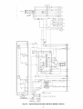
*If PremierLink control is in thermostat mode.
1-TB2 terminal designations for 24 vac discrete inputs. Default is for DDC control.
Fig. 25 -- PremierLink
TM
Controls
Wiring
CLO
-CMP
-ECONO-ENTH
-IGC
-MGV
-OAT
-PL
-SAT
-SPT
-TB
--
Compressor Lockout
Compressor
Economizer
Enthalpy Sensor
Integrated Gas Unit Controller
Main Gas Valve
Outdoor Air Temperature Sensor
Plug
Supply Air Temperature Sensor
Space Temperature Sensor
Terminal Block
FGROM
Table 8 -- PremierLink
OUTDOOR
TEMPERATURE
APPLICATION
AIR
SENSOR
TM
RETURN
TEMPERATURE
Sensor
AIR
SENSOR
Usage
OUTDOOR
AIR
ENTHALPY
SENSOR
RETURN AIR
ENTHALPY
SENSOR
--
--
DifferentialDryBulb
Temperature
with
PremierLink*
(PremierLink
requires
4-20 mA
Required -33ZCT55SPT
or Equivalent
Included-HH79NZ039
Actuator)
Single
Enthalpy
with
Required
PremierLink*
(PremierLink
requires
4-20 mA
Actuator)
Differential
Enthalpy
with PremierLink*
(PremierLink
requires
4-20 mA
Actuator)
--
33CSENTHSW
Included
--
--
(HH57ZC003)
NotUsed
or
HH57AC077
Included-NotUsed
33CSENTHSW
(HH57ZC003)
or
HH57AC077
Required
--
--
--
Required
--
33CSENTSEN
or
HH57AC078
*PremierLink control requires supply air temperature sensor 33ZCSENSAT and
outdoor air temperature sensor HH79NZ039 -- included with factory-installed PremierLink control;
field-supplied and field-installed with field-installed PremierLink control.
NOTES:
1. CO2 Sensors (Optional):
33ZCSENCO2 -- Room sensor (adjustable). Aspirator box is required for duct mounting of the sensor.
33ZCASPCO2 -- Aspirator box used for duct-mounted CO2 room sensor.
33ZCT55CO2 -- Space temperature and CO2 room sensor with override.
33ZCT56CO2 -- Space temperature and CO2 room sensor with override and setpoint.
2. All units include the following Standard Sensors:
Outdoor-air sensor -- 50HJ540569 -- Opens at 67 F, closes at 52 F, not adjustable.
Mixed-air sensor -- HH97AZ001 -- (PremierLink control requires supply air temperature sensor 33ZCSENSAT
and outdoor air temperature sensor HH79NZ039)
Compressor lockout sensor -- 50HJ540570 -- Opens at 35 E closes at 50 E
ENTHALPY SWITCH/RECEIVER
-- The accessory
enthalpy switclffreceiver
(33CSENTHSW)
senses temperature
and humidity of the air surrounding the device and calculates
the enthalpy when used without an enth_dpy sensol: The relay is
energized when enthalpy is high and deenergized when enthalpy is low (based on ASHRAE [American Society of Heating, Refrigeration and Air Conditioning Engineersl 90.1 criteria). If an accessory enthalpy sensor (33CSENTSEN)
is attached to the return air sensor input, then differential enth_dpy is
calculated. The relay is energized when the enthalpy detected by
the return air enth_dpy sensor is less than the enthalpy at the enthalpy switch/receivel: The relay is deenergized when the enthalpy detected by the return air enthalpy sensor is greater than
the enthalpy at the enthalpy switch/receiver
(differential enthalpy control). See Fig. 26 and 27.
intake). The enthalpy switch/receiver
is not a NEMA 4
(Natiomd Electrical Manufacturers
Association) enclosure and
should be mounted in a location that is not exposed to outdoor
elements such as rain or snow. Use two field-supplied no. 8 x
3/4-in. TEK screws. Insert the screws through the holes in the
sides of the enthalpy switchheceiver
Wiring -- Cmrier recommends
the use of 18 to 22 AWG
(American Wire Gage) twisted pair or shielded cable for all
wiring. All connections must be made with l/4-in, female spade
connectors.
A 24-vac transformer is required to power the enthalpy
switch/receiver; as shown in Fig. 29, the PremierLink TM board
provides 24 vac. Connect the GND and 24 VAC terminals on
the enthalpy switclffreceiver to the terminals on the transformer. On some applications, the power from the economizer harness can be used to power the enthalpy switclffreceivel:
To
power the enthalpy switclffreceiver from the economizer harness, connect power of the enthalpy switclffreceiver to the red
and brown wires (1 and 4) on the economizer hmness.
OUTDOOR ENTHALPY
CONTROL
(Fig. 28) -- Outdoor
enthalpy control requires only an enthalpy switclffreceiver
(33CSENTHSW).
The enthalpy switclffreceiver is mounted in
the outdoor air inlet and calculates outdoor air enthalpy. The
enthalpy switch/receiver
energizes the relay output when the
outdoor enthalpy is above 28 BTU/Ib OR @ bulb temperature is above 75 F and is deenergized
when the outdoor
enthalpy is below 27 BTU/Ib AND dry bulb temperature is
below 74.5 IF.The relay output is wired to the unit economizer
which will open or close depending on the output of the
switch.
NOTE: The enthalpy calculation
tude of 1000 ft above sea level.
is done using an average
For connection to rooftop units with PlemierLink TM control,
connect the LOW Enthalpy terminal on the enthalpy switch/receiver to J4 -- pin 2 of the PremierLink control on the HVAC
unit. The switch can be powered through the PremierLink control board if desired. Wire the 24 VAC terminal on the enthalpy
switch/receiver to J4 -- pin 1 on the PremierLink control. Wile
the GND terminal on the enthalpy switch/receiver
to Jl -pin 2 on the PremierLink control. The HI Enthalpy terminal is
not used. See Fig. 28.
alti-
Mounting -- Mount the enthalpy switch/receiver
in a location
where the outdoor air can be sampled (such as the outdoor air
19
fSensor
Thermistor
Thermistor
I
Fig. 26 -- Enthalpy SwitchlReceiver
(33CSENTHSW)
Dimensions
_
S
Humidi_
Sensor
Fig. 27 -- Enthalpy Sensor Dimensions
(33CSENTSEN)
/
o
.......
_(OR
UNIT GROUND)
\
*Used with Differential
Fig. 28 -- Typical Wiring Schematic -- Carrier Rooftop Unit with PremierLink
20
TM
Enthalpy Control only,
Controls
DIFFERENTIAL
ENTHALPY
CONTROL
(Fig. 29) -Diffemntifd enthalpy control mquiles both fin enthalpy switch/
receiver
(33CSENTHSW)
and
fin
enthalpy
sensor
(33CSENTSEN).
The enthalpy switchkeceiver
is mounted in
the outdoor air inlet and calculates outdoor air enthalpy. Tile
enthalpy sensor is mounted in the return airstream and cfflculates the enthalpy of the indoor all:
The PlemierLink TM board provides 24-vac to power the
enthfflpy switch/receivel: Connect the GND and 24 VAC terminals on the enthfflpy switch/receiver
to the terminals on
the transformer
On some applications,
the power from the
economizer hmness can be used to power the enthalpy switch/
leceivel: To power the enthalpy switchkeceiver
from the
economizer harness, connect power of the enthalpy switch/
receiver to the led and brown wires (1 and 4) on the economizer harness.
The enthalpy switclffleceiver energizes the HI Enthalpy relay output when the outdoor enthalpy is greater than file indoor
enthalpy. The LOW Enthalpy terminal is energized when the
outdoor enthalpy is lower than the indoor enthalpy. The relay
output is wired to the unit economizer which will open or close
depending on the output of the switch.
NOTE: The enthalpy calculation
tude of 1000 fl above sea level.
is done using an average
Connect the LOW Enthalpy
terminal on the enthalpy
switch/receiver to J4 -- pin 2 of the PlemierLink control on the
HVAC unit. The switch can be powered through the PremierLink control board if desired. Wire file 24VAC terminal on the
enthalpy switclffreceiver to J4 -- pin 1 on the PremierLink
control. Wire the GND terminal on the enthalpy switch/
receiver to Jl -- pin 2 on the PremierLink
control. The HI
Enthalpy terminal is not used. See Fig. 28.
alti-
Mounting -- Mount the enthalpy switch/receiver
in a location
where the outdoor air can be sampled (such as the outdoor air
intake). The enthalpy switch/receiver
is not a NEMA 4 enclosure fred should be mounted in a location that is not exposed to
outdoor elements such as rain, snow. or dilect sunlight. Use
two field-supplied no. 8 x 3/4-in. TEK screws. Insert the screws
through the holes in the sides of the enthalpy switclffreceivel:
Connect the 4-20 mA IN terminal on the enthalpy
receiver to the 4-20 mA OUT terminal on the return
thalpy sensor. Connect the 24-36 VDC OUT terminfd
enthalpy switch/leceiver to the 24-36 VDC IN terminal
return air enthalpy sensor. See Fig. 29.
switch/
air enon the
on the
Enthalpy Switch/Receiver
Jumper Settings -- There are two
jumpers. One jumper determines the mode of the enthalpy
switch/receivel:
The other jumper is not used. To access the
jumpers,
lemove the 4 screws holding the cover on the
enthalpy switclffreceiver find then remove the covel: The factory settings for the jumpers me M I and OFE
The mode jumper should be set to M2 for differential enthalpy control. The factory test jumper should remain on OFF
or the enthalpy switch/receiver will not calculate enthalpy.
Mount the enthalpy sensor in a location whele the indoor air
can be smnpled (such as the return air duct). The enthalpy
sensor is not a NEMA 4 enclosure and should be mounted in a
location that is not exposed to outdoor elements such as rain or
snow. Use two field-supplied no. 8 x 3/4-in. TEK screws. Insert
the screws through the holes in the sides of the enthalpy sensol:
Wiring -- Carrier recommends
the use of 18 to 22 AWG
twisted pair or shielded cable for all wiring. All connections
must be made with I/4-in. female spade connectors.
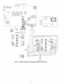
120 VAC
LINE VOLTAGE
_jk.jM.Z.__/
]
24 VAC OUTPUT
FROM
OUTDOOR
ENTHALPY
INDOOR
ENTHALPY
N/C CONTACT
IS LESS
THAN
WHEN
THE
THE
24 VAC OUTPUT
FROM N/O CONTACT
WHEN
INDOOR
ENTHALPY
IS GREATER
THAN THE
OUTDOOR
ENTHALPY
f
f
j!
,i ORN
/
THE 4--
HI LOW
ENTHALPY
GND
24
VAC
4-20 24-36
mA VDC
IN OUT
24-36
VDC
IN
4-20
mA
OUT
33CSENTSEN
33CSENTHSW
J
JUMPER
SETTINGS
FOR
33CSENTHSW
JUMPER
SETTINGS
FOR 33CSENTSEN
O
LEGEND
N/C -N/O --
Normally Closed
Normally Open
O0
Fig. 29 -- Differential Enthalpy Control Wiring
21
o
on
[l°°°l
000
Enthalpy Sensor Jumper Settings -- There me two jumpers.
One julnper determines the mode of the enthalpy sensor. The
other jumper is not used. To access the jumpers, relnove the
4 screws holding the cover on the enthalpy sensor and then remove the covel: The factory settings for the jumpers are M3
and OFF.
The mode jumper should be set to M3 for 4 to 20 mA
output. The factory test jumper should remain on OFF or the
enthalpy sensor will not calculate enth_dpy.
2.
At the enthalpy control remove the factory-installed
resistor fi_m the (SR) and (+) terminals.
3.
Connect the field-supplied
RED wire to (+) spade
connector on the return air enthalpy sensor and the (SR+)
terminal on the enthalpy controllel: Connect the BLK
wire to (S) spade connector on the return air enthalpy
sensor and the (SR) terminal on the enthalpy controller.
ENTHALPY CONTROLLER
ENTHALPY SENSORS AND CONTROL
-- The enthalpy
control (HH57AC077)
is supplied as a field-installed accessory
to be used with the EconoMiSer2 &unper control option. The
outdoor air enthalpy sensor is part of the enthalpy control. The
separate field-installed
accessory return air enthalpy sensor
(HH57AC078)
is required for differential enthalpy control.
RED
TR r_ TRI_""
AIR
/OUTDOOR
[
SENSOR)
ENTHALPY
BRN
BLK
RED
A( C SOD+rn-SRI-h+ID-___]1
NOTE: The enthalpy control must be set to the "D" setting for
differenti_d enthalpy control to work properly.
F[S (RETURN AIR I
[] + ENTHALPY
SENSOR
GRAY/ORN
LWIRE
LED
The enthalpy control receives
the indoor and return
enthalpy from the outdoor and return air enthalpy sensol_ and
provides a dry contact switch input to the PremierLink TM
controllel: Locate the controller in place of an existing economizer controller or near the actuatol: The mounting plate may
not be needed if existing bracket is used.
GRAY/RED
JIN
HARNESS
UNIT
NOTES:
1. Remove factory-installed jumper across SR and + before connecting wires from return air sensor,
2. Switches shown in high outdoor air enthalpy state. Terminals 2
and 3 close on low outdoor air enthalpy relative to indoor air
enthalpy.
3. Remove sensor mounted on back of control and locate in outside airstream.
A closed contact indicates that outside air is preferred to the
return air An open contact indicates that the economizer
should remain at minilnuln position.
Fig. 30 -- Outdoor and Return Air Sensor Wiring
Connections for Differential Enthalpy Control
Outdoor
Air
Enthalpy
Sensor/Enthalpy
Controller
(HH57AC077)
-- To wire the outdoor air enthalpy sensor,
perform the following (see Fig. 30 and 31 ):
NOTE: The outdoor air sensor can be removed froln the back
of the enth_dpy controller and mounted relnotely.
1. Use a 4-conductol,
18 or 20 AWG cable to connect the
enthalpy control to the PremierLink controller and power
tl_dnsformel:
HH57AC077
ENTHALPY
CONTROL AND
OUTDOOR AIR
ENTHALPY SENSOR
2.
Connect the following 4 wires fiom the wire h_uness
located in rooftop unit to the enthalpy controller:
a. Connect the BRN wire to the 24 vac terminal (TRI)
on enthalpy control and to pin 1 on 12-pin harness.
b. Connect the RED wire to the 24 vac GND terminal
(TR) on enthalpy sensor and to pin 4 on 12-pin
harness.
c. Connect the GRAY/ORN
wire to J4-2 on PremierLink controller and to terminal
(3) on enthalpy
sensor.
d. Connect the GRAY/RED
wire to J4-1 on PremierLink controller and to terminal (2) on enthalpy sensol:
NOTE: If installing in a Carrier rooftop, use the two gray wires
provided fiom the control section to the economizer to connect
PrelnierLink controller to terminals 2 and 3 on enth_dpy sensol:
HH57AC078 ENTHALPY
SENSOR (USED WITH
ENTHALPY CONTROL
FOR DIFFERENTIAL
ENTHALPY OPERATION)
Return Air Enthalpy Sensor -- Mount the return-air enthalpy
sensor (HH57AC078)
in the return-air duct. The return air
sensor is wired to the enthalpy controller (HH57AC077).
The
outdoor enth_dpy changeover set point is set at the controller.
To wire the return air enthalpy sensol; perform the following (see Fig. 30):
÷
÷
MOUNTING PLATE
e,
Fig. 31 -- Differential
Enthalpy Control,
Sensor and Mounting
Plate (33AMKITENT006)
1. Use a 2-conductor,
18 or 20 AWG, twisted pair cable to
connect the return air enthalpy sensor to the enthalpy
controller.
22
OPTIONAL
ECONOMISERIV
AND
See Fig. 32 and 33 for EconoMiSerIV
See Fig. 34 for EconoMi$er2 component
3. Reinstall economizer hood.
4. Install _dl EconoMiSerIV accessories. EconoMiSerlV
wiring is shown in Fig. 35. EconoMi$er2 wiring is shown
in Fig. 36.
ECONOMISER2
-component locations.
locations.
NOTE: These instructions
are for installing the optional
EconoMiSerIV
and EconoMiSer2 only. Refer to the accessory
EconoMiSerIV
or EconoMiSer2 installation instructions when
field installing an EconoMi$erIV
or EconoMiSer2 accessory.
Outdoor air leakage is shown in Table 9. Return air pressure
drop is shown in Table 10.
To complete inst_fllation of the optional EconoMiSerIV. perform the following procedure.
1. Remove the EconoMiSerIV
hood. Refer to Step 11 -- Install Outdoor-Air
Hood on page 14 for information on
removing and installing the outdoor-air hood.
2.
Relocate
position
Fig. 32.
Table 9 -- Outdoor
Table
10 --
Leakage
DAMPER STATIC PRESSURE (in. wg)
0.2
0.4
0.6
0.8
1.0
1.2
35
53
65
75
90
102
LEAKAGE (cfm)
outdoor air temperature sensor from shipping
to operation position on EconoMiSerIV.
See
Air Damper
Return
Air Pressure
Drop (in. wg)
CFM
4500
EconoMiSerIVFailure
not operating
I the
MPORTANT:
to relocate properly.
the sensor will result in
OUTDOOR
ECONOMI$ERIV
FRAME
IUb'
SCREWS
5000 5400
0.050
0.060
6000
7200 7500
9000 10,000 11,250
0.070
0.090
0.110
0.100
0.120
0.140
AIR
TEMPERATURE
SCREWS
0.040
(INSTALLED
POSITION)
SENSOR
FRAME
OPERATION
ECONOMISER2
SCREWS
SCREWS.
LOW TEMPERATURE
COMPRESSOR
LOCKOUT SWITCH
/
i_
Fig. 32--EconoMiSerlVComponent
End View
j
Locations-Fig. 34-
SUPPLY
AIR
TEMPERATURE
LOCATION
SENSOR
ECONOMI$ERIV
FLANGE
(HIDDEN)
[
Fig. 33 --
EconoMi$erlV
Component
Side View
Locations-
23
u
EconoMi$er2 Component
/J
7
N2
Locations
YEL
PNK
-8LU
RED
--
ORN
(FIE£B
ACCESSORY}
REMOTE MIN
POSITION POT
I_
BLK
POT (ISS_hmT
_E_T[
1
EXH
SET
[_
BV
IOV
[COBOMISER
BOARD
"
il
DISCHARGE AIR
SENSOR
(Bk
Ohm)
POS
BLK_I_EO
L1
_4
L1
-S
1 fIELD INSTALLED
-
OPEN
_IA_
2v
I F .....
IAO SENSOR
IBv
©
- (NOT BSEDI
L1-9
m
L
I I
OAT TEWPI
I 1
ENTHALPY SENSOR
PLI _8
I
I I
I
TO
MAIN
_Lu-
PLI _5
/
PL1-6
CONTROL
/_
IIT
I
I
PLI-II
1
_
SET
_v
lov
B
C
RETURN AIR TEHP!
ENTRALPY SEICSOR
1
BOX
_so. N
.T--
_---
1 l
BLU
I
PNK--_
l
I I FIELD
SPLICE
PLI*I
PLI _R
PL1-10
,_I
I I
FIELD
aR.
RED
LALS
SPLICE
(NOT USED)
ECONOMIZER
LEGEND
DCV -- Demand Controlled Ventilation
IAQ --Indoor
Air Quality
LALS I Low Temperature Compressor
Lookout Switch
OAT IOutdoor_Air
Temperature
POT -- Potentiometer
Potentiometer Default Settings:
Power Exhaust
Middle
Minimum Pos.
Fully Closed
DCV Max,
Middle
DCV Set
Middle
Enthalpy
C Setting
MOTOR
NOTES:
1, 620 ohm, 1 watt 5% resistor should be removed only when using differential
enthalpy or dry bulb.
2, If a separate field-supplied 24 v transformer is used for the IAQ sensor power
supply, it cannot have the secondary of the transformer grounded.
3, For field-installed
remote minimum position POT, remove black wire jumper
between P and P1 and set control minimum position POT to the minimum
position,
Fig. 35 -- EconoMi$erlV Wiring
4
3
7
RED
500 OHM
2
8
/
NOTE
RESISTOR-
"L_
PINK
6
1
BLUE
RUN
5
OAT
BLACK
1
NOTE 2
J
10
50HJ540573
ACTUATOR
ASSEMBLY
11
9
WHITE
DIRECT
DRIVE
ACTUATOR
12
ECONOMI$ER2
LEGEND
OAT -- Outdoor Air Temperature Sensor
NOTES:
1. Switch on actuator must be in run position for economizer to operate.
2. 50HJ540573 actuator consists of the 50HJ540567 actuator and a harness with 500-ohm resistor.
Fig. 36 -- EconoMi$er2 Wiring
24
PLUG
ECONOMISERIV
STANDARD
SENSORS
Table 12 -- EconoMi$erlV Sensor Usage
Outdoor Air Temperature
(OAT) Sensor -- The outdoor air
temperature sensor (HH57AC074)
is a 10 to 20 mA device
used to measure the outdoor-air temperature. The outdoor-air
temperature is used to determine when the EconoMiSerIV can
be used for free cooling. The sensor must be field-relocated.
See Fig. 32. The operating range of temperature measurement
is 40 to 100E
Accessories
Outdoor Air
Dry Bulb
Differential Dry Bulb
Single Enthalpy
Supply Air Temperature
(SAT) Sensor
-- The supply air
temperature sensor is a 3 K tl_ermistor located at the inlet of the
indoor fan. See Fig. 33. This sensor is factory inst_flled. The operating range of temperature measurement is 0 ° to 158 E See
Table 11 for sensor temperature/resistance
values.
The temperature sensor looks like an eyelet terminal
wires running to it. The sensor is located in the "crimp
and is settled from moisture.
Differential
with
end"
(F)
RESISTANCE
-40
100,680
-22
53,010
-4
29,091
14
15,590
32
9,795
50
5,970
68
3,747
77
3,000
86
2,416
104
1,597
122
1,080
140
745
158
525
176
376
185
321
194
274
212
203
230
153
248
115
257
102
266
89
284
70
302
55
ECONOMI$ERIV
CONTROL
Required
None. The outdoor air dry bulb sensor
is factory installed.
CRTEMPSN002A00*
HH57AC078
HH57AC078
and
CRENTDIF004A00*
33ZCSENCO2
and
33ZCSENCO2t
33ZCASPCO2**
CRCBDiOX005A00tt
Outdoor DLy Bulb Changeover
-- The standard controller is
shipped from the factory configured
for outdoor &y bulb
changeover control. The outdoor air and supply air temperature
sensors me included as standard. For this control mode, the
outdoor temperature is compmed to an adjustable set point selected on the control. If the outdoor-air temperature is above
the set point, the EconoMiSerIV
will adjust the outdoor-air
dampers to minimum position. If the outdoor-air temperature is
below the set point, the position of the outdoor-air dampers will
be controlled to provide free cooling using outdoor ail: When
in this mode, the LED next to the free cooling set point potentiometer will be on. The changeover
temperature set point is
controlled by the free cooling set point potentiometer located
on the control. See Fig. 37. The sc_fle on the potentiometer is A,
B, C, and D. See Fig. 38 for the corresponding
temperature
changeover values.
Differential Dry Bulb Control -- For differential dry bulb
control the standard outdoor @ bulb sensor is used in conjunction with an additional accessory return air sensor (part number
CRTEMPSN002A00).
The accessory sensor must be mounted
in the return airstream. See Fig. 39.
In this mode of operation, the outdoor-air temperature is
compared to the return-air temperature and the lower temperature airstream is used for cooling. When using this mode of
changeover control, turn the free cooling/enthalpy
set point
potentiometer fully clockwise to the D setting. See Fig. 37.
(ohms)
200,250
AIR
*CRENTDiF004A00
and CRTEMPSN002A00
accessories
are used on
many different base units. As such, these kits may contain parts that
will not be needed for installation.
1-33ZCSENCO2
is an accessory CO2 sensor.
**33ZCASPCO2
is an accessory
aspirator
box required
for ductmounted applications.
1-1-CRCBDIOX005A00
is an accessory that contains both 33ZCSENCO2
and 33ZCASPCO2
accessories.
Table 11 -- Supply Air Sensor Temperature/
Resistance Values
-58
Enthalpy
CO2 for DCV Control
using a Wall-Mounted
CO2 Sensor
CO2 for DCV Control
using a Duct-Mounted
CO2 Sensor
Low Temperature
Compressor
Lockout Switch
-- The
EconoMiSerIV is equipped with an ambient temperature lockout switch located in the outdoor airstrealn which is used to
lockout the compressols
below a 42 F ambient temperature.
See Fig. 32.
TEMPERATURE
ECONOMISERIV
WITH OUTDOOR
DRY BULB SENSOR
APPLICATION
EXHAUST
FAN SET POINT
LED LIGHTS
WHEN EXHAUST
CONTACT IS MADE
MODES
MINIMUM
POSITION
a controllel: The EconoMiSer2 is operated by a 4 to 20 mA
signal from an existing field-supplied controller (such as
IMPORTANT:
option_d
doesinformation.
not include
PrelnierLink TM The
control).
See EconoMi$er2
Fig. 36 for wiring
DAMPER
SETTING
MAXIMUM DAMPER
DEMAND CONTROL
VENTILATION
SET POINT
LED LIGHTS WHEN
DEMAND CONTROL
VENTILATION
iNPUT
IS ABOVE SET POINT
Determine the EconoMiSerlV control mode befole set up of
the control. Some modes of operation may lequire diffelent sensors. Refer to Table 12. The EconoMi$erlV
is supplied from the
factory with a supply air temperature sensor, a low temperature
complessor
lockout switch, and an outdoor air temperature
sensol: This allows for operation of the EconoMi$erIV
with
outdoor air diy bulb changeover control. Additional accessories can be added to _dlow for different types of changeover
control and operation of the EconoMiSerlV and unit.
DEMAND CONTROL
VENTILATION SET POINT
LED LIGHTS WHEN
OUTDOOR AIR IS
SUITABLE FOR
FREE COOLING
FREE COOLING / ENTHALPY
CHANGEOVER
SET POINT
Fig.
25
37 --
EconoMi$erlV
Controller
and LED Locations
Potentiometer
19
I
LED ON
18
17
16- --
_ED ON
- LED OFF
15
<
E14
LED O;
13
_<
12
LED ON-- --
"t,4
11
lO
I
9
40
45
50
65
55
DEGREES
LED{ OFF
70
75
80
85
90
95
100
FAHRENHEIT
Fig. 38 -- Outside Air Temperature
Changeover Set Points
Outdoor Enthalpy Changeover
-- For enthalpy control, ticcessoq
enthalpy
sensor (part number
HH57AC078)
is
required. Replace the stan&ud outdoor dry bulb temperature
sensor with the accessory enthalpy sensor in the same mounting location. See Fig. 32. When the outdoor tfir enthalpy rises
above the outdoor enth_@y changeover set point, the outdoorair damper moves to its minimum position. The outdoor
enthalpy changeover set point is set with the outdoor enthalpy
set point potentiometer on the EconoMiSerIV
controllel: The
set points are A, B, C, and D. See Fig. 40. The factory-installed
620-ohm jumper must be in place across terminals SR and SR+
on the EconoMiSerIV controllel: See Fig. 32 and 41.
Fig. 39 -- Return Air Temperature or
Enthalpy Sensor Mounting Location
45 _+15 second delay before exhaust fan actiw_tion to allow the
dampers to open. This delay _fllows the damper to reach the
appropriate position to avoid unnecessary fan overload.
Differential Enthalpy Control
-- For differential
enthalpy
control, the EconoMiSerIV
controller uses two enthalpy sensors (HH57AC078
and CRENTDIF004A00),
one in the outside air and one in the return airstream or the EconoMiSerIV
frmne. The EconoMiSerIV
controller compares the outdoor tfir
enthalpy to the return tfir enthalpy to determine EconoMiSerIV
use. The controller selects the lower enthalpy air (return or outdoor) for cooling. For example, when the outdoor air has a lower enthalpy than the return air and is below the set point, the
EconoMiSerIV opens to bring in outdoor air for free cooling.
Minimum Position Control -- There is a minimum damper
position potentiometer
on the EconoMi$erIV
controllel: See
Fig. 37. The minimum dmnper position mainttfins the minimum airflow into the building during the occupied period.
When using demand ventilation, the minimum &tmper position represents the minimum ventilation position for VOC
(volatile organic compound)
ventilation requirements.
The
maximum demand ventilation position is used for fully occupied ventilation.
Replace the standard outside air ch_ bulb temperature sensor with the accessory enth_dpy sensor in the same mounting
location. See Fig. 32. Mount the return air enthalpy sensor in
the return airstream.
See Fig. 39. The outdoor enthalpy
changeover set point is set with the outdoor enth_flpy set point
potentiometer
on the EconoMiSerIV
controllel: When using
this mode of changeover control, turn the enth_flpy set point
potentiometer fiJlly clockwise to the O setting.
NOTE: Remove
sor is installed.
620-ohm
resistor if differential
enthalpy
RETURN
AIR
TEMPERATURE
OR ENTHALPY
SENSOR
IAQ
SENSOR
When demand
minimum position
cupied ventilation
position should be
ventilation control is not being used, the
potentiometer should be used to set the ocposition. The maximum demand ventilation
turned fully clockwise.
Adjust the minimum position potentiometer
to _fllow the
minimum amount of outdoor air. as required by local codes, to
enter the building. Make minimum position adjustments with
at least 10° F temperature difference between the outdoor and
return-air temperatures.
sen-
Indoor Air Quality (IAQ) Sensor [nput -- The IAQ input
can be used for demand control ventilation control based on the
level of CO2 measured in the space or return air duct.
To determine the minimum position setting, perform the
following procedure:
1. Calculate the appropriate mixed-air temperature using the
following formula:
Mount the accessory IAQ sensor according to manufacturer
specifications. The IAQ sensor should be wired to the AQ and
AQI terminals of the controllel: Adjust the DCV potentiometers to correspond to the DCV voltage output of the indoor tfir
quality sensor at the user-determined
set point. See Fig. 42.
OA ) + (TR x _RA
(To x l-T-if(]-
) = TM
To = Outdoor-Air Temperature
OA = Percent of Outdoor Air
If a sepmate field-supplied transformer is used to power the
IAQ sensor, the sensor must not be grounded
or the
EconoMiSerlV control bomd will be damaged.
TR = Return-Air Temperature
RA = Percent of Return Air
Exhaust Set Point Adjustment
-- The exhaust set point will
determine when the exhaust fan runs based on dmnper position
(if accessory power exhaust is installed). The set point is modified with the Exhaust Fan Set Point (EXH SET) potentiometel:
See Fig. 37. The set point represents the cktmper position above
which the exhaust fan will be turned on. When there is a
c_dl for exhaust, the EconoMiSerIV
controller provides a
TM = Mixed-Air Temperature
As an example, if local codes require 10% outdoor
during occupied conditions, outdoor-_fir temperature
60 IF.and return-air temperature is 75 IF.
(60 x. 10) + (75 x .90) = 73.5 F
26
air
is
85
(29)
CONTROL
CURVE
CONTROL POINT
APPROX. °F (°C)
AT 50% RH
A
73 (23)
B
70 (21)
C
D
67/19)
63 (17)
90
(32)
95
(35)
\1
100
(38)
/I
XI
105
(41)
110
(43)
\
IX
_
CURVE
35
40
45
(2)
(4)
(7)
APPROXIMATE
50
55
(10)
(13)
DRY BULB
60
65
70
75
(16)
(18)
(21)
(24)
TEMPERATURE--
80
85
90
95
100
105
110
(27)
(29)
(32)
(35)
(38)
(41)
(43)
°F (°C)
Fig. 40 -- Enthalpy Changeover
...........................................
TRr_'_
Set Points
TR1
CO 2 SENSOR MAX RANGE SETTING
6000
5000
o_
Z
iO
DCV
2
2
3000
OV
4
,7Z
©
O
w
EF1
:_
CE
5
_AO_
DCV
so+
N
AOlI'_ocv_
4000
CE
'
SO_l_JI
SR+
tee
sR_1__1
_7 °
..... ..... ....
Fig. 41 -- EconoMi$erlV
2000
1000
2
DAMPER
Controller
3
VOLTAGE
4
5
FOR
MAX
6
VENTILATION
7
8
RATE
Fig. 42 -- 002 Sensor Maximum Range Setting
27
2.
Disconnect
TI.
the supply-air
3.
Ensure that
terminals P
used, make
Fig. 35 and
turned fully
Connect 24
file factory-installed jumper is in place across
and PI. If remote damper positioning is being
sure that file tenninals are wired according to
that the minimum position potentiometer
is
clockwise.
vac across terminals TR and TRI.
4.
5.
sensor from termimds
T and
ventilation required to remove contmninants during unoccupied periods. Tile following equation may be used to determine
the percent of outside-air entering the building for a given
damper position. For best results there should be at least a
10 degree difference in outside and return-air temperatures.
OA
RA
(To x l---ff_) + (TR x _
) = TM
To = Outdoor-Air Temperature
OA = Percent of Outdoor Air
Carefiflly adjust the minimum position potentiometer
until the measured mixed-air temperature matches the
c_dculated value.
TR = Return-Air Telnperature
RA = Percent of Return Air
TM = Mixed-Air Temperature
Once base ventilation has been determined, set the minimum damper position potentiometer to the correct position.
The same equation can be used to determine the occupied or
maximum ventilation rate to the building. For example, an output of 3.6 volts to the actuator provides a base ventilation rate
of 5% and an output of 6.7 volts provides the maximum ventilation rate of 20% (or base plus 15 cfm per person). Use Fig. 42
to determine the maximum setting of file CO2 sensoc For example, a 1100 ppm set point relates to a 15 cfm per person design. Use the 1100 ppm curve on Fig. 42 to find the point when
the CO2 sensor output will be 6.7 volts. Line up the point on the
graph with the left side of the chart to determine that the range
configuration for the CO2 sensor should be 1800 ppm. The
EconoMiSerIV controller will output the 6.7 volts fiom the
CO2 sensor to the actuator when the CO__concentration in the
space is at 1100 ppm. The DCV set point may be left at 2 volts
since the CO2 sensor voltage will be ignored by the
EconoMiSerIV controller until it rises above the 3.6 volt setting
of the minimum position potentiomete_:
Once the fully occupied dmnper position has been determined, set file maximum dmnper demand control ventilation
potentiometer to this position. Do not set to the maximum position as this can result in over-ventilation to the space and potential high-humidity levels.
CO2_Sensor Configuration -- The CO2 sensor has preset
standard voltage settings that can be selected anytime after the
sensor is powered up. See Table 13.
6. Reconnect the supply-air sensor to terminals T and TI.
Remote control of the EconoMiSerIV
damper is desilable
when requiring
additional
tempormy
ventilation.
If a
field-supplied remote potentiometer (Honeywell part number
$963B1128) is wired to the EconoMiSerIV
controllek the minimum position of the damper can be controlled from a remote
location.
To control the minimum damper position lemotely, remove
the factory-installed
jumper on the P and Pl terminals on the
EconoMi$erIV
controllec Wire the field-supplied potentiolneter to the P and Pl terminals on the EconoMiSerIV
controllec
See Fig. 41.
Damper Movement -- Damper movement from full open to
full closed (or vice velsa) takes 21/2 minutes.
Thermostats
-- The EconoMiSerIV
control works with conventional thermostats that have a YI (cool stage 1), Y2 (cool
stage 2), WI (heat stage 1), W2 (heat stage 2), _md G (fan). The
EconoMiSerIV
control does not support space temperature
senso_.s. Connections are made at the thermostat terminal connection board located in the main control box.
Occupancy Control -- The factory default configuration for
the EconoMiSerIV
control is occupied mode. Occupied status
is provided by the red jumper from terminal 9 to terminal 10 on
TB2. When unoccupied
mode is desired, install a fieldsupplied timeclock fimction in place of the jumper between terminals 9 and 10 on TB2. See Fig. 35. When the timeclock
contacts me closed, file EconoMiSer[V
control will be in
occupied mode. When the timeclock contacts are open (removing the 24-v signal from termimd N), the EconoMiSerlV
will
be in unoccupied mode.
Demand Controlled Ventilation (DCV) -- When using the
EconoMiSerlV
for demand controlled ventilation, there me
some equipment selection criteria which should be considered.
When selecting the heat capacity and cool capacity of the
equipment, the maximum ventilation rate must be evaluated for
design conditions. The maximum damper position must be c_dculated to provide the desired fresh ail:
Use setting 1 or 2 for Carrier equipment. See Table 13.
1. Press Clear and Mode buttons. Hold at least 5 seconds
until the sensor enters the Edit mode.
2. Press Mode twice. The STDSET Menu will appear
3. Use the Up/Down button to select the preset numbel: See
Table 13.
Typically file maximum ventilation rate will be about 5 to
10% more than the typical cfm required per pel.son, using
normal outside air design criteria.
A proportional anticipatory strategy should be taken with
the following conditions: a zone with a large area, varied occupancy, and equipment that cannot exceed the required ventilation rate at design conditions. Exceeding the required ventilation rate means the equipment can condition air at a maximum
ventilation rate that is greater than the required ventilation rate
for maximum occupancy. A proportional-anticipatory
strategy
will cause file fresh air supplied to increase as the room COz
level increases even though the CO2 set point has not been
reached. By the time the CO2 level reaches the set point, the
dmnper will be at maximum ventilation and should maintain
the set point.
4.
Press Enter to lock in file selection.
5.
Press Mode to exit and resume norm_d operation.
The custom settings of the CO2 sensor can be changed anytime after the sensor is energized. Follow the steps below to
change file non-stan&trd settings:
1. Press Clear and Mode buttons. Hold at least 5 seconds
until the sensor enters the Edit mode.
In order to have the CO2 sensor control the economizer
dmnper in this manner, first determine the damper voltage output for minimum or base ventilation. Base ventilation is the
28
2.
Press Mode twice. The STDSET
3.
Use the Up/Down
and press Entel:
Menu will appem:
4.
Use the Up/Down button to toggle through each of the
nine variables, starting with Altitude, until file desired setting is reached.
5.
Press Mode to move through the variables.
6.
Press Enter to lock in the selection,
continue to the next vmiable.
button to toggle to the NONSTD
menu
then press Mode to
Table 13 -- 002 Sensor Standard
OUTPUT
VENTILATION
RATE
(cfm/Pereon)
Proportional
Any
Proportional
Any
3
Exponential
Any
4
Proportional
15
Proportional
20
6
Exponential
15
7
Exponential
20
SETTING
EQUIPMENT
1
2
Interface with Standard
Building Control System
5
Economizer
8
Health & Safety
Proportional
9
Parking/Air Intakes/
Loading Docks
Proportional
ANALOG
OUTPUT
Settings
002
CONTROLRANGE
(ppm)
0-10V
4-20 mA
2-10V
7-20 mA
0-10V
4-20 mA
0-10V
4-20 mA
0-10V
4-20 mA
0-10V
4-20 mA
0-10V
4-20 mA
0-10V
4-20 mA
0-10V
4-20 mA
OPTIONAL
RELAY SETPOINT
(ppm)
RELAY
HYSTERESIS
(ppm)
0-2000
1000
50
0-2000
1000
50
0-2000
1100
50
0-1100
1100
50
0- 900
900
50
0-1100
1100
50
0- 900
900
50
0-9999
5000
50O
0-2000
700
50
LEGEND
ppm -- Parts Per Million
Dehumidification
of Fresh
Air with
DCV
Control
--
Step 14 -- Install Humidistat
for Optional
MoistureMi$er TM Package-MoistureMi$er
dehu-
Infor-
mation flom ASHRAE
indicates
that the largest humidity
load
on any zone is the flesh air introduced.
For some applications,
a field-installed
energy
recovely
unit can be added to reduce
the moisture
content
of file fiesh tfir being brought
into the
midification
package
operation
can be controlled
by field installation
of a Canier-approved
humidistat.
To install the humidistat perform the following
procedure:
building
when the enthalpy
is high. In most cases, the normal
heating and cooling
processes
are more than adequate
to remove the humidity
loads for most commerci_d
applications.
1.
a dehumidification
option
should
humidistat
on a solid
tioned space. Location
should
to sense average
humidity.
If nonnal
rooftop heating
and cooling operation
is not adequate for the outdoor
humidity
level, an enel_y recovery
unit
and/or
Locate
2.
be considered.
29
interior
wall
be a well
in the condi-
ventilated
area
Route thermostat
cable or equivalent
single leads of colored wire from Humidistat
terminals through conduit
in
unit to the low voltage connection
on the 2-pole terminal
strip (TB3) as shown in Fig. 43 and Fig. 44. See Fig. 45
for operation_d
diagram.
MOISTUREMI$ER
_-_YELTO CRANKCASE
1HEATER CIRCUITS
BLK
YEL
?-_
BLK_
TRAN
24V
BLK
TRANt
2_4_
GRN-YEL
GRN-YEL
LEGEND
CB
LLSV
LPS
TB
TRAN
------
BLK
Circuit Breaker
Liquid Line Solenoid Valve
Low-Pressure Switch
Terminal Block
Transformer
S-LPS1
CB4
TB3
BLK--
3.2 AMPS
FACTOR
(OR HUMIDISTATIF
S LPS2
USED)
Fig. 43Typical MoistureMi$er TM Dehumidification Package
Humidistat Wiring Schematic (460 V Unit Shown)
f I[L D CONTROL
FACTORY _RSIALLEO JURPER
(REMOVE IF RUM_OISTAT IS USED)
Fig. 44 -- Typical MoistureMi$er Dehumidification
Package Control Box
30
LLSVksv_
L
_
CONDENSER
l
COiL
,
DISCHARGE
OUTDOOR
AiR
SUBCOOLER
COIL
SUCTION
F
/
EQUALIZER
LINE
CCH
CRANKCASE
HEATER
EVAPORATOR
COIL
3-WAY
VALVE
S-LPS J
SUB COOLERCONTROL
LOW PRESSURESWITCH
TXV
TXV
TM
Dehumidification
START-UP
Use the following information and Start-Up
page CL-I to check out unit PRIOR to start-up.
Checklist
on
-- Check that unit has been installed in
with these installation instructions and all applica-
COMPRESSOR
MOUNTING
complessor holddown bolts.
--
power leads.
the scroll comwhich will actireset. Reset is
off.
connections in
CRANKCASE
HEATER (SIZE 028 AND UNITS WITH
MOISTUREMI$ER
TM DEHUMIDIFICATION
PACKAGE
ONLY) -- Crankcase heater(s) is energized as long as there is
power to the unit and the compressor is not operating.
I
I start-up.
MPORTANT:
Otherwise,
Unit &mmge
power must
to thebecompressor
on for 24 houB
may result.
prior to I
EVAPORATOR
FANFan belt and vmiable pulleys are
factory-installed.
Remove
tape from the fan pulley. See
Tables 14-19 for fan performance data. Be sure that fans rotate
in the proper direction. See Table 20 for air quantity limits. See
Tables 21-23 for static pressure information for accessories and
options. See Table 24 for fan rpm tit motor pulley settings. See
Tables 25 and 26 for evaporator-fan motor data and evaporatorfan motor efficiency. To alter fan performance, see Evaporator
Fan Perforlnance Adjustment section on page 40.
48TJ024 and 028 Only -- It is important to be certain the
compressors are rotaing in the proper direction. To determine
whether or not compressoB are rotaing in the proper direction:
Connect service gages to suction and discharge pressure
fittings.
Energize the compressoc
The suction pressure should &op and the discharge pressure should rise, as is normal on any start-up.
fan is probably
power to the unit.
any two of the incoming
power to the unit.
each compressoc
After a few minutes of reverse operation,
pressor intermfl overload protection will open,
vate the unit's lockout and requires a manual
accomplished by turning the thermostat on and
INTERNAL
WIRING -- Check all electrical
unit control boxes; tighten as required.
48TJ016 and 020 Only -- The unit is equipped with a Phase
Monitor Relay (PMR) board located in the control box. The
PMR device will not allow the unit to run if field power is connected incorrectly. To determine if the Phase Monitor Relay is
preventing the unit from starting, check to see if the red LED is
blinking, ff the LED is blinking, the 3-phase field power has
been wiled incorrectly. A solid light means that field power
connections are correct.
1. Note that the evaporator
in the wrong direction.
Diagram
NOTE: When compressors are rotating in the wrong direction,
the unit will have increased noise levels and will not provide
heating and cooling.
Do not loosen or remove
If the suction pressure does not drop and the discharge
sure does not rise to normal levels:
Turn off
Reverse
Turn on
Energize
Operation
The suction and discharge pressure levels should now move
to their normtd start-up levels.
REFRIGERANT
SERVICE PORTS -- Each reh'igerant system has a total of 3 Schrader-type service gage ports. One port
is located on the suction line, one on the compressor discharge
line, and one on the liquid line. In addition Schmder-type
valves are located underneath the low-pressme
switches. Be
sure that caps on the polls are tight.
COMPRESSOR
ROTATION
2.
3.
Package
2.
3.
4.
5.
Unit Preparation
I.
AIR
-- Thermostatic Expansion Valve
Fig. 45 -- MoistureMi$er
accordance
ble codes.
INDOOR
NOTE: A 31/2-in. bolt and threaded plate are included in the
installer's packet for 48TJ020-028 units. They can be added to
the motor support channel below the motor mounting plate to
aid in raising the fan motor
pres-
also rotating
31
Table 14 -- Fan Performance -- 48TJD016 (Low Heat Units)
AVAILABLE
AIRFLOW
(cfm)
4500
4800
5100
5400
5700
6000
6300
6600
6900
7200
7500
0.2
Rpm
809
850
892
934
976
1019
1063
1106
1150
AIRFLOW
(cfm)
4500
4800
5100
5400
5700
6000
6300
6600
6900
7200
7500
Bhp
1.83
1.76
2.01
2.28
2.58
2.90
3.24
3.61
4.00
0.4
Watts
1317
1516
1733
1970
2225
2500
2795
3111
3448
Rpm
906
942
979
1017
1058
1096
1136
1177
1218
Bhp
2.87
3.13
3.41
3.71
4.04
Watts
1502
1706
1928
2169
2429
2709
3008
3329
3670
AVAILABLE
1.6
1,4
Rpm
1301
1324
1349
1374
1402
Bhp
1.74
1,98
2.24
2.52
2,82
3,14
3,49
3,86
4,26
Watts
2477
2700
2942
3202
3481
Rpm
1369
1390
1413
1437
1463
Bhp
3,11
3,37
3,88
3,96
4.29
Rpm
Bhp
994
1.96
1027
2.20
1061
2,46
1096
2,75
1132
3,06
1168
3,38
1206
3,74
1244
4,11
............
EXTERNAL
Watts
2683
2909
3153
3418
3699
EXTERNAL
0,6
Rpm
1434
1454
1475
1498
.........
Watts
1690
1899
2125
2371
2635
2919
3223
3547
STATIC PRESSURE
0,8
Rpm
1078
1107
1138
1170
1204
1238
1273
1309
STATIC PRESSURE
1,8
Bhp
3,35
3,62
3,90
4,21
Watts
2891
3120
3367
3633
LEGEND
Rpm
1497
1515
1535
......
Bhp
2.18
2.43
2.70
2.99
3.30
3.63
3,99
4.37
(in. wg)
1.0
Watts
1882
2094
2325
2575
2843
3131
3439
3767
Rpm
1156
1183
1211
1241
1272
1304
1337
......
Bhp
2.41
2,66
2,93
3.22
3.54
3.88
4.24
Watts
2997
3226
3475
Rpm
1497
1515
1535
Bhp
3,80
3,87
4,18
(in. wg)
1.9
1.2
Watts
2077
2293
2528
2781
3053
3345
3657
Rpm
1230
1255
1281
1309
1338
1368
--
Bhp
2,64
2,89
3,17
3,47
3,79
4,13
--
Watts
2275
2495
2733
2990
3266
3562
--
2.0
Bhp
3.47
3.74
4.03
Watts
3103
3334
3584
3. Static pressure losses (i.e., economizer) must be added to external static
pressure before entering Fan Performance table.
4. Interpolation is permissible. Do not extrapolate.
5. Fan performance is based on wet coils, clean filters, and casing losses.
See Tables 21-23 for accessory/FlOP static pressure information.
6. Extensive motor and drive testing on these units ensures that the full
horsepower and watts range of the motor can be utilized with confidence. Using fan motors up to the watts or bhp rating shown will not
result in nuisance tripping or premature motor failure. Unit warranty will
not be affected.
7. Use of a field-supplied motor may affect wiring size. Contact your Carrier
representative for details.
Bhp
-- Brake Horsepower
FlOP
-- Factory-Installed Option
Watts -- Input Watts to Motor
NOTES:
1, Standard low-medium static drive range is 891 to 1179 rpm (for 208/230
and 460-v units) or 1159 to 1429 rpm (for 575-v units). Alternate highstatic drive range is 1227 to 1550 (for 208/230 and 460-v units), The
alternate high-static drive is not available for 48TJ016 575-v units. Other
rpms require a field-supplied drive,
2, Maximum continuous bhp is 4.25 (208/230 and 460 v) or 3,45 (575 v)
and the maximum continuous watts are 3775 (208/230 and 460 v) or
3065 (575 v). Do not adjust motor rpm such that motor maximum bhp
and/or watts is exceeded at the maximum operating cfm.
Table 15 -- Fan Performance -- 48TJD020 and 024 (Low Heat Units)
AVAILABLE
AIRFLOW
(cfm)
5,500
6,000
6,500
7,000
7,500
8,000
8,500
9,000
9,500
10,000
0,2
EXTERNAL
0,6
STATIC PRESSURE
0,8
----
1.0
1,2
Bhp
Watts
Rpm
Bhp
Watts
Rpm
Bhp
Watts
Rpm
Bhp
Watts
Rpm
Bhp
Watts
Rpm
Bhp
Watts
755
810
868
923
980
1038
1096
1154
1213
1272
2,27
2,72
3,22
3,78
4,39
5,08
5.78
6,56
7.40
8,30
1908
2287
2710
3177
3690
4251
4859
5517
6224
6983
831
881
932
985
1038
1093
1148
1204
1260
1317
2.58
3.04
3.55
4.11
4.73
5.40
6.13
6.92
7.77
8.67
2171
2556
2985
3458
3976
4542
5156
5818
6531
7294
901
947
994
1044
1094
1148
1198
1251
1306
1360
2.91
3.37
3.88
4.45
5.07
5.75
8.49
7,28
8.13
9.05
2443
2833
3288
3744
4267
4838
5458
6123
6840
7608
968
1010
1054
1100
1148
1197
1247
1298
1350
1403
3.24
3,71
4,23
4.80
5.43
6.11
6.85
7.65
8.51
9.43
2723
3118
3554
4036
4564
5138
5761
6432
7154
7926
1031
1070
1111
1155
1200
1248
1294
1343
1394
1445
3.58
4.05
4.57
5,15
5.78
6.47
7.22
8.02
8.88
9.81
3009
3408
3847
4333
4864
5443
6070
6745
7471
8247
1091
1127
1166
1207
1250
1294
1340
1388
1436
1486
3,93
4,40
4,93
5,51
6,15
6,84
7,59
8,40
9,26
10.19
3302
3702
4148
4635
5170
5752
6382
7062
7791
8570
Watts
4375
4780
5232
5729
6273
6866
7506
8196
Rpm
1309
1337
1368
1402
1437
1475
1514
--
Bhp
5,39
5,87
6,41
7,00
7.65
8,36
9,12
--
AVAILABLE
1.6
1.4
Rpm
1149
1183
1219
1258
1299
1341
1385
1431
1478
Bhp
4.28
4.76
5.29
5.88
6.52
7.21
7.97
8.78
9.65
Watts
3602
4003
4450
4942
5480
6065
6699
7382
8114
Rpm
1204
1238
1270
1307
1346
1387
1429
1473
1519
Bhp
4,65
5,13
5,66
6,25
6,89
7,59
8,35
9,15
10,04
EXTERNAL
Watts
3907
4310
1459
5253
5794
6383
7019
7705
8441
Rpm
1258
1288
1320
1355
1392
1392
1472
1515
STATIC PRESSURE(in.
1,8
Bhp
5,02
5,50
6,03
6,62
7,27
7,97
8,73
9,55
Watts
4217
4622
5073
5569
6113
6704
7343
8032
.......
Rpm
1284
1313
1344
1378
1415
1453
1493
1535
LEGEND
Bhp
FlOP
Watts
(in. wg)
Rpm
AIRFLOW
(cfm)
5,500
6,000
6,500
7,000
7,500
8,000
8,500
9,000
9,500
10,000
0,4
Brake Horsepower
Factory-Installed Option
Input Watts to Motor
3.
4.
5.
NOTES:
1, Standard low-medium static drive range for the 020 size is 910 to
1095 rpm. Standard low-medium static drive range for the 024 size is
1002 to 1225 rpm. Alternate high-static drive range for the 020 size is
1069 to 1287, Alternate hig h-static drive range for the 024 size is 1193 to
1458 rpm. Other rpms require a field-supplied drive,
2, Maximum continuous bhp for the 020 size is 5,90. Maximum continuous
bhp for the 024 size is 8.7 (208/230, 575 v) or 9.5 (460 v). The maximum
continuous watts for the 020 size is 5180. The maximum continuous
watts for the 024 size is 7915 (208/230, 575 v) or 8640 (460 v). Do not
6.
7.
32
wg)
1.9
Bhp
5,20
5.68
6.22
6,81
7,46
8,16
8,93
9,75
2.0
Wat_
4533
4939
5391
5890
6435
7028
7670
--
adjust motor rpm such that motor maximum
bhp and/or watts is
exceeded at the maximum operating cfm.
Static pressure losses (i.e., economizer) must be added to external static
pressure before entering Fan Performance table.
Interpolation is permissible. Do not extrapolate.
Fan performance is based on wet coils, clean filters, and casing losses.
See Tables 21-23 for accessory/FlOP static pressure information.
Extensive motor and drive testing on these units ensures that the full
horsepower and watts range of the motor can be utilized with confidence. Using fan motors up to the watts or bhp rating shown will not
result in nuisance tripping or premature motor failure. Unit warranty will
not be affected.
Use of a field-supplied motor may affect wiring size. Contact your Carrier
representative for details.
Table 16 -- Fan Performance -- 48TJD028 (Low Heat Units)
AVAILABLE
AIRFLOW
(cfrn)
7,000
7,500
8,000
8,500
9,000
9,500
10,000
10,500
11,000
11,250
Rpm
941
999
1056
1117
1177
1237
1297
1358
1418
1449
Watts
2769
3346
4007
4750
5583
6511
7450
8674
9919
10585
AVAILABLE
1,4
AIRFLOW
(cfm)
7,000
7,500
8,000
8,500
9,000
9,500
10,000
10,500
11,000
11,250
0.2
Bhp
3,35
4,05
4,85
5,74
6,75
7,98
9,12
10,49
12,00
12,80
Rpm
1274
1316
1360
1406
1453
1501
Bhp
6.35
7.20
8.14
9.20
10,36
11,64
Watts
5248
6960
6734
7605
8568
9627
0.4
Rpm
Bhp
1002
3.60
1057
4.53
1113
5.35
1169
6.28
1226
7.31
1284
8.46
1342
9.74
1400
11.14
1459
12.67
...............
EXTERNAL
Rpm
1323
1364
1406
1449
1495
1541
Watts
3140
3742
4424
5190
6047
6999
8051
9209
10478
Rpm
1061
1112
1165
1219
1274
1329
1385
1442
............
STATIC PRESSURE
1,6
Bhp
6,92
7,79
8,76
9,83
11.02
12,32
Watts
5718
6437
7239
8129
9111
10190
EXTERNAL
0.6
Bhp
4,27
5,02
5,87
6,83
7,89
9,07
10,37
11,80
Watts
3528
4152
4856
5645
6524
7499
8574
9755
----
0.8
Bhp
4.76
5.54
6.41
7.40
8.48
9.69
11.02
12.47
Rpm
1117
1166
1216
1268
1320
1374
1428
1483
(in. wg)
Watts
3934
4579
5304
6114
7015
8012
9110
10314
Rpm
1171
1218
1266
1315
1365
1417
1469
1523
1.0
Bhp
5.27
6.07
6,97
7,98
9,09
10,33
11,68
13,16
Watts
4356
5020
5766
6597
7520
8538
9657
10883
Rpm
1224
1266
1314
1361
1410
1459
1510
--
1.2
Bhp
5.60
6.63
7.55
6.58
9.72
10.98
12.36
--
Watts
4794
5478
6243
7094
8037
9076
10217
--
(in, wg)
1,8
Rpm
1371
1410
1450
1492
1536
--
Bhp
5.54
6.41
7.40
8.48
9.69
--
Watts
6204
6939
7759
8666
9667
--
LEGEND
Bhp
FlOP
Watts
STATIC PRESSURE
3. Static pressure losses (i,e., economizer) must be added to external static
pressure before entering Fan Performance table,
4. Interpolation is permissible. Do not extrapolate,
5. Fan performance is based on wet coils, clean filters, and casing losses.
See Tables 21-23 for accessory/FlOP static pressure information,
6. Extensive motor and drive testing on these units ensures that the full
horsepower and watts range of the motor can be utilized with confidence, Using fan motors up to the watts or bhp rating shown will not
result in nuisance tripping or premature motor failure. Unit warranty will
not be affected.
7. Use of a field-supplied motor may affect wiring size. Contact your Carrier
representative for details,
Brake Horsepower
Factory-Installed Option
Input Wattsto Motor
NOTES:
1. Standard low-medium static drive range is 1066 to 1283 rpm, Alternate
high-static drive range is 1332 to 1550. Other rpms require a fieldsupplied drive,
2. Maximum continuous bhp is 10.2 (208/230, 575 v) or 11.8 (460 v) and
the maximum continuous watts are 9510 (208/230, 575 v) or 11,000
(460 v). Do not adjust motor rpm such that motor maximum bhp and/or
watts is exceeded at the maximum operating cfm.
Table 17 -- Fan Performance -- 48TJF016 (High Heat Units)
AVAILABLE
AIRFLOW
(cfm)
0,2
Rpm
819
861
904
947
990
1034
1078
1123
1167
4500
4800
5100
5400
5700
6000
6300
6600
6900
7200
AIRFLOW
(cfm)
45OO
4800
5100
5400
5700
6000
6300
6600
6900
7200
Bhp
1,55
1,78
2,04
2,32
2,62
2,94
3,29
3,67
4,06
0,4
Watts
1335
1538
1759
1999
2259
2539
2840
3161
3504
Rpm
914
951
989
1028
1068
1109
1150
1192
1234
Bhp
2.88
3,14
3,43
3,73
4,06
Watts
1518
1726
1952
2197
2461
2745
3050
3376
3723
AVAILABLE
1.6
1.4
Rpm
1304
1327
1353
1380
1408
.......
.......
.......
.......
.......
Bhp
1,76
2,00
2,26
2,55
2,85
3,18
3,54
3,91
4,32
Watts
2484
2711
2955
3219
3503
Rpm
1371
1393
1417
1442
1468
Bhp
3.12
3,38
3,67
3,98
4,31
Watts
2688
2917
3165
3432
3718
Rpm
1001
1035
1069
1105
1142
1180
1218
1258
............
EXTERNAL
Rpm
1435
1456
1478
1502
--
EXTERNAL
0.6
Bhp
1,98
2,22
2,49
2,78
3,09
3,42
3,78
4,16
Watts
1705
1916
2147
2396
2665
2953
3262
3592
STATIC PRESSURE
0,8
Rpm
1083
1113
1145
1179
1213
1248
1284
.........
STATIC PRESSURE
1.8
Bhp
3.36
3,62
3,92
4,23
Watts
2895
3126
3377
3646
Rpm
1467
1486
1508
1531
LEGEND
Bhp
FlOP
Watts
----
Brake Horsepower
Factory-Installed Option
Input Wattsto Motor
3.
4.
5.
NOTES:
1. Standard low-medium static drive range is 891 to 1179 rpm (for 208/230
and 460-v units) or 1159 to 1429 rpm (for 575-v units). Alternate highstatic drive range is 1227 to 1550 (for 208/230 and 460-v units). The
alternate high-static drive is not available for 48TJ016 575-v units, Other
rpms require a field-supplied drive,
2. Maximum continuous bhp is 4,25 (208/230 and 460 v) or 3.45 (575 v)
and the maximum continuous watts are 3775 (208/230 and 460 v) or
6.
7.
.3.3
Bhp
2.20
2.45
2,72
3,01
3,33
3.67
4.03
(in, wg)
1.0
Watts
1894
2110
2345
2598
2871
3163
3476
Rpm
1160
1188
1218
1248
1280
1313
1348
Bhp
2,42
2,68
2,95
3,25
3,57
3,91
4,28
Watts
2999
3232
3484
3755
Rpm
1497
1517
1537
Bhp
3.60
3.87
4.16
(in, wg)
1.9
Bhp
3,48
3,75
4,04
4,35
1.2
Watts
2088
2307
2545
2802
3079
3375
3692
Rpm
1234
1259
1287
1315
1345
1376
--
Bhp
2,65
2,91
3,17
3,49
3,81
4,16
--
Watts
2284
2507
2749
3009
3289
3589
--
2.0
Watts
3104
3338
3592
3065 (575 v). Do not adjust motor rpm such that motor maximum bhp
and/or watts is exceeded at the maximum operating cfm,
Static pressure losses (i,e., economizer) must be added to external static
pressure before entering Fan Performance table,
Interpolation is permissible. Do not extrapolate,
Fan performance is based on wet coils, clean filters, and casing losses.
See Tables 21-23 for accessory/FlOP static pressure information,
Extensive motor and drive testing on these units ensures that the full
horsepower and watts range of the motor can be utilized with confidence, Using fan motors up to the watts or bhp rating shown will not
result in nuisance tripping or premature motor failure, Unit warranty will
not be affected.
Use of a field-supplied motor may affect wiring size. Contact your Carrier
representative for details,
Table 18 -- Fan PerformanceAVAILABLE
AIRFLOW
(cfm)
5_500
6,000
6,500
7,000
7,500
8,000
8,500
9,000
9,500
10,000
Rpm
795
854
914
975
1037
1099
1161
1223
1286
1349
AIRFLOW
(cfm)
5,500
6,000
6,500
7,000
7,500
8,000
8,500
9,000
9,500
10,000
0.2
Bhp
2.43
2.92
3.46
4.06
4.72
5.44
6.22
7.07
7.98
8.95
Watts
2043
2452
2909
3414
3969
4575
5232
5943
6708
7528
Rpm
866
921
977
1034
1092
1150
1210
1270
1331
1392
Bhp
4.44
4.95
5.53
6.16
6.85
7.60
8.41
9.28
10.22
Watts
2306
2722
3184
3695
4255
4866
5529
6245
7014
7839
AVAILABLE
1,6
1.4
Rpm
1173
1211
1252
1295
1340
1388
1436
1486
1538
0.4
Bhp
2.74
3.24
3.79
4.39
5.06
5.79
6.57
7.43
8.34
9.32
W_
3732
4165
4646
5176
5756
6388
7071
7807
8597
Rpm
1227
1263
1302
1343
1386
1431
1478
1527
............
Bhp
4.80
5.32
5.89
6.52
7.22
7.97
8.79
9.67
EXTERNAL
0.6
Bhp
3.07
3.57
4.12
4.73
5.41
6.14
6.93
7.79
8.71
9.70
Rpm
934
984
1036
1090
1145
1201
1258
1315
1374
1433
EXTERNAL
Watts
4036
4471
4954
5487
6070
6704
7390
8130
48TJF020 and 024 (High Heat Units)
STATIC PRESSURE
Watts
2578
3998
3465
3981
4546
5162
5829
6550
7324
8154
Rpm
998
1044
1093
1144
1196
1249
1304
1360
1416
1473
STATIC PRESSURE
1,8
Rpm
1279
1313
1350
1389
1431
1474
1520
.........
Bhp
5.17
5.69
6.26
6.90
7.60
8.35
9.17
Wat_
4345
4782
5267
5802
6387
7024
7713
Rpm
1304
1337
1373
1412
1452
1495
1540
LEGEND
Bhp
FlOP
Watts
----
Brake Horsepower
Factory-Installed Option
Input Watts to Motor
3.
4.
5.
NOTES:
1. Standard low-medium static drive range for the 020 size is 910 to
1095 rpm. Standard low-medium static drive range for the 024 size is
1002 to 1225 rpm. Alternate high-static drive range for the 020 size is
1069 to 1287. Alternate hig h-static drive range for the 024 size is 1193 to
1458 rpm. Other rpms require a field-supplied drive.
2. Maximum continuous bhp for the 020 size is 5.90. Maximum continuous
bhp for the 024 size is 8.7 (208/230, 575 v) or 9.5 (460 v). The maximum
continuous watts for the 020 size is 5180. The maximum continuous
watts for the 024 size is 7915 (208/230, 575 v) or 8640 (460 v). Do not
6.
7.
0.8
Bhp
3.40
3.90
4.46
5.08
5.76
6.50
7.29
8.16
9.08
10.07
(in. wg)
Watts
2856
3281
3752
4272
4842
5462
6134
6869
7638
8471
Rpm
1059
1102
1148
1196
1256
1297
1349
1403
1457
......
(in. wg)
1,9
Bhp
5.35
5.87
6.56
7.09
7.79
8.54
9.37
1.0
Bhp
3.74
4.25
4.81
5.43
6.12
6.86
7.66
8.53
9.46
Watts
3142
3570
4045
4569
5142
5766
6443
7171
7954
Rpm
1117
1158
1201
1246
1294
1343
1393
1445
1498
1.2
Bhp
4.08
4.60
5.16
5.79
6.48
7.22
8.03
8.90
9.84
Watts
3434
3865
4343
4870
5447
6075
6755
7487
8274
2,0
Watts
4502
4939
5425
5961
6547
7186
7876
Rpm
1329
1361
1396
1434
1474
1516
--
Bhp
5.54
6.06
6.64
7.28
7.98
8.74
--
Watts
4629
5097
5584
6121
6709
7348
--
adjust motor rpm such that motor maximum
bhp and/or watts is
exceeded at the maximum operating cfm.
Static pressure losses (i.e., economizer) must be added to external static
pressure before entering Fan Performance table.
Interpolation is permissible. Do not extrapolate.
Fan performance is based on wet coils, clean filters, and casing losses.
See Tables 21-23 for accessory/FlOP static pressure information.
Extensive motor and drive testing on these units ensures that the full
horsepower and watts range of the motor can be utilized with confidence. Using fan motors up to the watts or bhp rating shown will not
result in nuisance tripping or premature motor failure. Unit warranty will
not be affected.
Use of a field-supplied motor may affect wiring size. Contact your Carrier
representative for details.
Table 19 -- Fan Performance -- 48TJF028 (High Heat Units)
AVAILABLE
AIRFLOW
(cfm)
7,000
7,500
8,000
8,500
9,000
9,500
10,000
10,500
11,000
11,250
0.2
Rpm
Bhp
Watts
Rpm
992
1055
1118
1182
1246
1310
1374
1439
1503
1536
4.05
4.77
5.58
6.46
7.42
8.47
9.61
10.84
12.17
12.86
3,348
3,947
4,610
5,339
6,136
7,005
7,947
8,964
10,059
10,636
1051
4.44
1110
5.17
1170
5.99
1231
6.88
1292
7.86
1354
8.92
1416
10.07
1479
11.32
1542
12.65
...............
AVAILABLE
1.4
AIRFLOW
(cfm)
7,000
7,500
8,000
8,500
9,000
9,500
10,000
10,500
11,000
11,250
0.4
Rpm
1311
1358
1406
1456
1507
Bhp
6.51
7.30
8.17
9.12
10.15
Watts
5385
6039
6767
7541
8393
EXTERNAL
Rpm
1359
1403
1560
1498
1548
Bhp
Rpm
Bhp
Watts
Rpm
3,668
4,277
4,950
5,690
6,498
7,377
8,329
9,356
10,460
1106
4.83
1162
5.58
1220
6.41
1278
7.31
1337
8.30
1397
9.38
1457
10.54
1518
11.79
............
3995
4615
5298
6047
6865
7754
8715
9752
1160
5.24
1214
6.00
1268
6.84
1324
7.75
1381
8.75
1439
9.84
1497
11.02
.........
Watts
5751
6412
7137
7929
8790
Rpm
1405
1448
1492
1539
--
----
Bhp
(in. wg)
1,0
1.2
Watts
Rpm
Bhp
Watts
Rpm
Bhp
Watts
4331
4960
5653
6411
7239
8137
9107
1212
1263
1315
1369
1424
1480
1537
5.65
6.43
7.27
8.20
9.21
10.31
11.50
4675
5312
6014
6782
7618
8525
9504
1262
1311
1361
1413
1466
1520
--
6.08
6.86
7.72
8.66
9.68
10.79
--
5026
5672
6382
7158
8003
8918
--
(in. wg)
1.8
Bhp
6.00
6.84
7.75
8.75
--
Watts
6124
6792
7524
8323
--
LEGEND
Bhp
FlOP
Watts
STATIC PRESSURE
0.8
Watts
STATIC PRESSURE
1.6
Bhp
6.96
7.76
8.63
9.59
10.63
EXTERNAL
0.6
3. Static pressure losses (i.e., economizer) must be added to external static
pressure before entering Fan Performance table.
4. Interpolation is permissible. Do not extrapolate.
5. Fan performance is based on wet coils, clean filters, and casing losses.
See Tables 21-23 for accessory/FlOP static pressure information.
6. Extensive motor and drive testing on these units ensures that the full
horsepower and watts range of the motor can be utilized with confidence. Using fan motors up to the watts or bhp rating shown will not
result in nuisance tripping or premature motor failure. Unit warranty will
not be affected.
7. Use of a field-supplied motor may affect wiring size. Contact your Carrier
representative for details.
Brake Horsepower
Factory-Installed Option
Input Watts to Motor
NOTES:
1. Standard low-medium static drive range is 1066 to 1283 rpm. Alternate
high-static drive range is 1332 to 1550. Other rpms require a fieldsupplied drive.
2. Maximum continuous bhp is 10.2 (208/230, 575 v) or 11.8 (460 v) and
the maximum continuous watts are 9510 (208/230, 575 v) or 11,000
(460 v). Do not adjust motor rpm such that motor maximum bhp and/or
watts is exceeded at the maximum operating cfm.
34
Table 20 -- Air Quantity Limits
MINIMUM
HEATING CFM
MINIMUM
COOLING
CFM
UNIT
48TJ
016
020
4500
5400
Low Heat
3800
4750
024
028
6000
7000
4750
4750
MAXIMUM
CFM
High Heat
3800
5450
5450
5450
7,500
9,000
10,000
11,250
Table 21 -- Accessory/FlOP
Static Pressure*
(in. wg) -- 48TJ016
COMPONENT
4500
5000
CFM
6000
7200
7500
Economizer
0.04
0.05
0.07
0.09
0.10
LEGEND
FlOP -- Factory-Installed
Option
*The static pressure must be added to external static pressure. The sum and the
evaporator entering-air cfm should then be used in conjunction with the Fan Performance tables to determine blower rpm and watts.
Table 22 -- Accessory/FlOP Static Pressure*
(in. wg) -- 48TJ020-028
COMPONENT
5000
6000
7200
CFM
9000
Economizer
0.06
0.07
0.09
0.11
10,000
I
11,250
0.12
I
0.14
LEGEND
FlOP -- Factory-Installed
Option
*The static pressure must be added to external static pressure, The sum and the
evaporator entering-air cfm should then be used in conjunction with the Fan Performance tables to determine blower rpm and watts.
Table 23 -- MoistureMi$er TM Dehumidification
Package Static Pressure Drop (in. wg)
UNIT NOMINAL
TONS
UNIT SIZE
48TJ016
15
18
2O
25
48TJ020
48TJ024
48TJ028
300
CFM PER TON
4OO
.040
.058
.071
.111
.071
.102
.126
.197
500
.111
.160
.197
.308
Table 24 -- Fan Rpm at Motor Pulley Settings*
UNIT
48TJ
0
lr2
1
11/2
2
MOTOR PULLEY TURNS OPEN
2112
3
31/2
4
41/2
5
5112
6
016 (208/230, 460 v)t
tt
tt
1179
1150
1121
1093
1064
1035
1006
978
949
920
891
016 (208/230, 460 v)**
1-t
1-t
1559
1522
1488
1455
1422
1389
1356
1323
1289
1256
1227
016 (575 v)l"
0201"
1-t
1-t
1-t
1-t
1429
1095
1403
1077
1376
1058
1349
1040
1323
1021
1296
1002
1269
984
1242
965
1215
947
1188
928
1159
910
020**
tt
1-t
1287
1265
1243
1222
1200
1178
1156
1134
1112
1091
1069
0241"
1-t
1-t
1225
1209
1187
1165
1143
1120
1098
1076
1053
1031
1002
024**
tt
1-t
1456
1434
1407
1381
1354
1326
1301
1275
1246
1222
1193
0281"
1-t
1-t
1283
1269
1247
1225
1203
1182
1160
1136
1116
1095
1066
028**
1-t
1-t
tl-
tl-
1551
1524
1497
1470
1443
1415
1386
1361
above,
field-supplied
*Approximate fan rpm shown.
l-Indicates standard drive package,
**Indicates alternate drive package.
ttDue to belt and pulley size, pulley cannot be set to this number of
turns open.
NOTE: For speeds
required.
35
not
listed
1332
drives
are
Table 25 -- Evaporator-Fan
UNIT
48TJ
Motor Data
UNIT
VOLTAG E
MAXIMUM
ACCEPTABLE
CONTINUOUS BHP*
MAXIMUM
ACCEPTABLE
CONTINUOUS BkW*
208/230
4.25
3.17
3,775
10.5
460
4.25
3.17
3,775
4.8
575
208/230
3.45
2.59
3,065
460
5.90
4.40
5,180
7.9
575
208/230
8.70
6.49
7,915
22.0
460
9.50
7.08
8,640
13.0
575
208/230
8.70
6.49
7,915
10.0
10.20
7.61
9,510
28.0
460
11.80
8.80
11,000
14.6
575
10.20
7.61
9,510
13.0
016
020
024
028
MAXIMUM
ACCEPTABLE
OPERATING WATTS
MAXIMUM
AMP DRAW
3.9
15.8
6.0
LEGEND
BHP -BkW --
Brake Horsepower
Brake Kilowatts
*Extensive motor and electrical testing on these units ensures that the full horsepower (brake kilowatt)
range of the motors can be utilized with confidence. Using your fan motors up to the horsepower (brake
kilowatt) ratings shown in this table will not result in nuisance tripping or premature motor failure. Unit
warranty will not be affected.
NOTE: All indoor-fan motors 5 hp and larger meet the minimum efficiency requirements
the Energy Policy Act of 1992 (EPACT) effective October 24, 1997.
Table 26 -- Evaporator-Fan
UNIT 48TJ
Motor Efficiency
MOTOR EFFICIENCY
016 (3.0 Hp)
81.7
016 (3.7 Hp)
65.6
020 (5 Hp)
67.5
024 (7.5 Hp)
66.5
028 (10 Hp)
69.5
Operating
by
Sequence
COOLING,
UNITS WITHOLTT ECONOMIZER
-- When
thermostat calls for cooling, terminals G and Y I are energized.
The indoor (evaporator) fan contactor (IF(?_), compressor contactor no. 1 (CI) and outdoor-fan contactor (OFC) are energized, and evaporator-fan motor, compressor no. 1, and both
condenser fans stall. The condenser-fan motors mn continuously while unit is cooling. If the thermostat calls for a second stage
of cooling by energizing Y2, compressor contactor no. 2 (C2) is
energized and compressor no. 2 starts.
(%)
NOTE: All indoor-fan motors 5 hp and larger meet the minimum efficiency requirements as established by the Energy Policy Act of 1992
(EPACT) effective October 24, 1997.
When the thermostat is satisfied, CI and C2 tue deenergized and the compressors and outdoor (condenser) fan motors
(OFM) shut off. After a 30-second delay, the indoor (evaporator) fan motor (IFM) shuts off. If the thermostat fan selector
switch is in the ON position, the evaporator-fan motor will run
continuously.
CONDENSER-FANS
AND MOTORS
-- Condenser fans
and motol.'s am factol T set. Refer to Condenser-Fan Adjustment
section (page 42) as required. Be sure that fans rotate in the
proper direction.
RETURN-AIR
FILTERSCheck that correct filtel.s are
installed in filter tracks (see Table 1). Do not operate unit without return-air filters.
OUTDOOR-AIR
INLET SCREENS
-Outdoor-air
screens must be in place before operating unit.
as established
HEATING. UNITS WITHOUT
ECONOMIZER
-- When
the thermostat calls for heating, terminal WI is energized. In
order to prevent thermostat short-cycling, the unit is locked
into the Heating mode for at least 1 minute when WI is energized. The induced-draft motor (IDM) is then energized and
the burner ignition sequence begins. The indoor (evaporator)
fan motor (IFM) is energized 45 seconds after a fame is
ignited. On units equipped for two stages of heat, when additional heat is needed, W2 is enelgized and the high-fire solenoid on the main gas valve (MGV) is energized. When the
thermostat is satisfied and WI and W2 are deenergized, the
IFM stops after a 45-second time-off delay.
COOLING. UNITS WITH ECONOMISERIV
-- When
free
cooling is not available, the compressol_ will be controlled by
the zone thermostat.
When free cooling is available, the
outdoor-air &unper is modulated by the EconoMiSerIV control
to provide a 50 to 55 F supply-air temperature into the zone. As
the supply-air temperature fluctuates above 55 or below 50 IF.
the &lmpers will be modulated (open or close) to bring the
supply-air temperature back within the set point limits.
inlet
GAS HEAT -- Verify gas pressmes before turning on heat as
follows:
1. Turn off manual gas stop.
2. Connect pressure gage to supply gas pressure tap (see
Fig. 13).
3. Connect pressure gage to manifold pressure tap on gas
valve.
4. Turn on manual gas stop and set thermostat to HEAT
position. Adjust set point to several degrees above the
current room temperature to ensure a heat demand. After
the unit has mn for sevend minutes, verify that incoming
pressure is 5.5 in. wg or greater, and that the manifold
pressure is 3.3 in. wg. If manifold pressure must be adjusted, refer to Gas Valve Adjustment section on page 43.
5. After unit has been in operation for 5 minutes, check temperature rise across the heat exchangers. See unit informative plate for correct rise limits of the heat supplied.
Air quantities may need to be adjusted to bring the actual
rise to within the zdlowable limits.
For EconoMiSerIV
operation, there must be a thermostat
call for the fan (G). This will move the damper to its minimum
position during the occupied mode.
36
Above
50Fsupply-air
temperature,
thedmnpers
willmodulatefrom100%
open
totheminimum
openposition.
From50F
to 45F supply-air
temperature,
the&tmpers
will maintain
attheminimum
openposition.
Below45Fthe&lmpers
will
becompletely
shut.Asthesupply-air
temperature
rises,the
dampers
will comebackopentotheminimum
openposition
once
thesupply-air
temperatme
rises
to48IF.
If optional
powerexhaust
is inst_dled,
astheoutdoor-air
damper
opens
andcloses,
thepower
exhaust
fanwillbeenergizedanddeenergized.
If field-installed accessory COz sensors are connected to the
EconoMiSerIV control, a demand controlled ventilation strategy will begin to operate. As the CO2 level in the zone increases
above the CO2 set point, the minimum position of the &_mper
will be increased proportionally. As the CO2 level decreases
because of the inclease in fresh aik the outdoor-air damper will
be proportionally closed. Daraper position will follow the higher demand condition from DCV mode or free cooling mode.
•
•
•
< OAT < 68 F)
If only YI energized, the economizer
maintains a SASP
= (SATLOI + 3).
If SAT > SASP + 5 and economizer
position > 80%,
economizer will go to minimum position for 3 minutes or
until SAT > 68 IF.
First stage of mechanical cooling will be energized.
Integrator resets.
Economizer
opens again and controls to current SASP
after stage one on for 90 seconds.
With YI and Y2 energized
economizer
maintains
an
SASP = SATLO2 + 3.
If SAT > SASP + 5 and economizer
position >80%,
economizer will go to minimum position for 3 minutes or
until SAT > 68 E
If compressor
one is on then second stage of mechanical
cooling will be energized. Otherwise the first stage will
be energized.
Integrator resets.
Economizer
opens again and controls
to SASP after
stage one on for 90 seconds.
Routine
•
•
3 (OAT > 68)
Economizer
is opened 100%.
Compressors
1 and 2 are cycled based on YI and Y2
using minimum on and off times and watching the supply air temperature
as compared
to SATLOI
and
SATLO2 set points.
If optiomd power exhaust is installed, as the outdoor-air
&tmper opens and closes, the power exhaust fans will be energized and deenergized.
If field-installed accessory CO2 sensors me connected to the
PremierLink
control, a PlD-controlled
demand ventilation
strategy will begin to operate. As the CO2 level in the zone
increases above the CO2 set point, the minimum position of the
&_mper will be increased proportionally.
As the COz level
decreases because of the increase in fresh air, the outdoor-air
&tmper will be proportionally closed.
HEATING, UNITS WITH ECONOMISER2,
PREMIERLINK
CONTROL AND A THERMOSTAT -- When the thermostat
calls for heating, terminal Wl is energized. The PremierLink
control will move the economizer damper to the minimum
position if there is a call for G and closed if there is a call for
WI without G In order to prevent thermostat from short cycling, the unit is locked into the heating mode for at least
10 minutes when WI is energized. The induced-di'aft motor is
then energized and the burner ignition sequence begins.
The PremierLink control will use the following information
determine if free cooling is available:
Indoor fan has been on for at least 30 seconds.
The SPT. SAT. and OAT inputs must have valid readings.
OAT must be less than 75 F.
OAT must be less than Sir[ '.
Enthalpy must be LOW (may be jumpered if an enthalpy
sensor not available).
• Economizer
position is NOT forced.
to
•
•
•
•
•
On units equipped for two stages of heat, when additional
heat is needed, W2 is energized and the high-fire solenoid on
the main gas valve (MGV) is energized. When the thermostat
is satisfied and WI is deenergized,
the IFM stops after a
45-second time-off delay unless G is still maintained.
Pre-cooling occurs when the is no call fi_m the thermostat
except G Pre-cooling is defined as the economizer modulates
to provide 70 F supply air
COOLING,
UNITS WITH ECONOMISER2,
PREMIERLINK CONTROL
AND A ROOM SENSOR -- When free
cooling is not available, the compressors will be controlled by
the PremierLink controller using a PID Enor reduction calculation as indicated by Fig. 46.
When free cooling is available the PremierLink control will
control the compressors and economizer to provide a supplyair tempemtme determined to meet the YI and Y2 c_dls from
the thermostat using the following three routines. The three
control routines are based on OAT.
The PremierLink controller will use the following information to determine if free cooling is available:
• Indoor fan has been on for at least 30 seconds.
• The SPT. SAT. and OAT inputs must have valid readings.
• OAT must be less than 75 E
• OAT must be less than SPT.
• Enthalpy
must be LOW (may be jumpered
if and
enthalpy sensor is not available).
• Economizer
position is NOT forced.
The 3 routines ;ue based on OAT where:
SASP = Supply Air Set Point
Cooling Ix_ckout Set Point
PID = Proportional Integral
Routine 1 (OAT < DXCTLO)
YI energized
(SATLOI + 3).
Y2 energized
(SATLO2 + 3).
•
•
•
•
If free cooling can be used as determined from the appropriate changeover command (switch, diy bulb, enthalpy curve,
differential dry bulb, or differential enthalpy), a call for cooling
(YI closes at the thermostat) will cause the control to modulate
the &tmpeLs open to maintain the supply air temperature set
point at 50 to 55 E
As the supply-air temperature diops below the set point
range of 50 to 55 E the control will modulate the outdoor-air
dampers closed to maintain the proper supply-air temperature.
HEATING, UNITS WITH ECONOMISERIV
-- When the
room thermostat calls for heat, the heating controls are energized as described in the Heating, Units Without Economizer
section. When the indoor fan is energized, the economizer
damper moves to the minimum position. When the indoor fan
is off. the economizer dmnper is fully closed.
COOLING.
UNITS WITH ECONOMISER2,
PREMIERLINK TM CONTROL AND A THERMOSTAT
-- When free
cooling is not available, the compressoLs will be controlled by
the PremierLink control in response to the YI and Y2 inputs
from the thermostat.
= Dilect Expansion
•
•
Damper movement from full closed to lifll open (or vice
veLsa) will take between 11/2and 21/: minutes.
DXCTLO
Routine 2 (DXCTLO
•
economizer
maintains
a
SASP
=
economizer
maintains
a
SASP
=
When free cooling is available, the outdoor-air damper is
positioned through the use of a Proportional
Integral (PID)
control process to provide a calculated supply-air temperature
37
intothezone.
Thesupply
airwillmaintain
thespace
temperaturebetween
theheating
andcooling
setpoints
asindicated
in
Fig.47.
ThePremierLink
TM will integrate
the compressol_ stages
with the economizer based on similar logic as the three routines
listed in the previous section. The SASP will float up and down
based on the error reduction calculations that compare space
temperature and space set point.
If Heating PID STAGES=2
•
•
•
•
•
•
•
•
HEAT STAGES=I
HEAT STAGES=2
(75% capacity) will energize HSI
(100% capacity) will energize HS2
In order to prevent short cycling, the unit is locked into the
Heating mode forat least 10 minutes when HSI is deenergized.
When HSI is energized the induced-di'aft
motor is then
energized and the burner ignition sequence begins. On units
equipped for two stages of heat, when additional heat is needed, HS2 is energized and the high-fire solenoid on the main gas
valve (MGV) is energized. When the space condition is satisfied and HSI is deenergized the IFM stops after a 45-second
time-off delay unless in the occupied mode. The fan will run
continuously
in the occupied mode as lequired by nafiomd
energy and fiesh air standards.
The high space set point is used for DX (direct expansion)
cooling control, while the economizer space set point is a
c:dculated value between the heating and cooling set points.
The economizer set point will always be at least one degree
below the cooling set point, allowing for a smooth transition
from mechanical
cooling with economizer
assist, back to
economizer
cooling as the cooling set point is achieved.
The compressors
may be used for initkd cooling then the
PremierLink controller will modulate the economizer using an
enor reduction calculation
to hold the space temperature
between the heating and cooling set points. See Fig. 47.
conditions
If the PremierLink controller detemfines that heat stages are
required, the economizer dalnper will be moved to minimum
position if occupied and closed if unoccupied.
Staging should be as follows:
When outdoor-air temperature conditions require the economizer to close for a compressor stage-up sequence, the economizer control integrator is reset to zero after the stage-up sequence is completed. This prevents the supply-tOT temperature
from &'opping too quickly and creating a freeze condition that
would make the compressor turn off prematurely.
The controller uses the following
economizer cooling:
If all of the above conditions m'e met, the number of heat
stages is c_dculated; otherwise the required number of heat
stages will be set to 0.
TEMPERATURE
CONTROL
to determine
w
Enthalpyis
Low
SAT reading is available
OAT reading is available
SPT reading is available
OAT < SPT
Economizer
Position is NOT forced
75,
•_ 73
w
72 ...............................................
""" SET POINT
2:
71
--
TEMPERATURE
_- 70
W
o
694
cO
If any of the above conditions me not met, the economizer
submaster reference (ECSR) is set to maximum limit and the
dmnper moves to minimum position. The operating sequence
is complete. The ECSR is recalculated every 30 seconds.
68J
TIME
NOTE: PremierLink control performs smart staging of 2 stages of DX
cooling and up to 3 stages of heat.
If an optional power exhaust is inst:dled, as the outdoor-air
dmnper opens and closes, the power exhaust fans will be
energized and deenergized.
Fig. 46 -- DX Cooling Temperature
Control Example
If field-installed
accessory CO2 sensors are connected to
the PlemierLink control, a PID-controlled
demand ventilation
strategy will begin to operate. As the CO2 level in the zone
increases above the CO2 set point, the minimum position of the
dmnper will be increased proportionally.
As the CO2 level
decreases because of the increase in fresh all: the outdoor-air
dalnper will be proportionally closed.
HEATING. UNIT WITH ECONOMI$ER2,
PREMIERLINK
CONTROL AND A ROOM SENSOR -- Every 40 seconds
the controller will calculate the required heat stages (maximum
of 3) to maintain supply air temperature (SAT) if the following
qualifying conditions are met:
• Indoor fan has been on for at least 30 seconds.
• COOL mode is not active.
• OCCUPIED,
TEMRCOMPENSATED
START or HEAT
mode is active.
• SAT reading is available.
• Fire shutdown mode is not active.
TEMPERATURE
W
QZ
QZ
W
Q_
W
W
75
73
741_
"
72
......... _
71 t
_
704 ........
69
09
CONTROL
68
J
/j
_
....................................
------ COOL SETPOINT
X_"_H%_,_-_'-
--
..........................
TEMPERATURE
-- - HEAT
TIME
Fig. 47 -- Economizer
Temperature
Control Example
38
SETPOINT
SERVICE
aluminum,
pro-coated, copper/copper
or E-coated coils be
cleaned with the Totaline environmentally
sound coil cleaner
as described below. Coil cleaning should be part of the unit's
reguhuty scheduled maintenance procedures to ensure long life
of the coil. Failure to clean the coils may result in reduced durability in the environment.
Avoid the use of:
• Coil brighteners
• Acid cleaning prior to painting
• High pressure washers
• Poor quality water for cleaning
Before performing service or maintenance operations on
unit, turn off main power switch to unit and install lockout
tag on disconnect switch. Electrical shock could cause personal injury.
Cleaning-
Inspect unit interior at beginning
of each
heating and cooling season and as operating conditions require
(see Fig. 48). Remove unit top panel and/or side panels for access to unit interioc
Totaline environmentally
sound coil cleaner is non-flammable, hypoallergenic, nonbacterial, and a USDA accepted biodegradable agent that will not harm the coil or surrounding components such as electrical wiring, painted metal surfaces, or insulation. Use of non-recommended
coil cleaners is strongly
discouraged since coil and unit durability could be affected.
COIL MAINTENANCE
AND CLEANING
RECOMMENDATION -- Routine cleaning of coil surfaces is essential to
maintain proper operation of the unit. Elimination of contmnination and remowd of harmful residues will greatly increase
the life of the coil and extend the life of the unit. The following
maintenance and cleaning procedures are recommended as part
of the routine maintenance activities to extend the life of the
coil.
INDUCED DRAFT
MOTOR
INTEGRATED GAS
UNIT CONTROLLER
(HIDDEN)
VIEW
PORT
Totaline Environmentally
Sound
Equipment
• 21/2 gallon garden sprayer
• Water rinse with low velocity
Coil
Cleaner
Al)l)lRz_tion
spray nozzle
CONTROL BOX
ACCESS PANEL
Harsh chemicals, household bleach or acid or basic cleaners should not be used to clean outdoor or indoor coils of
any kind. These cleaners can be very difficult to rinse out
of the coil and can accelerate corrosion at the fin/tube interface where dissimilar materials are in contact. If there is
dirt below the surface of the coil, use the Totaline environmentally sound coil cleaner as described above.
ilGC
FAULT
High velocity water fi'om a pressure washeL garden hose,
or compressed air should never be used to clean a coil. The
force of the water or air jet will bend the fin edges and
increase airside pressure drop. Reduced unit performance
or nuisance unit shutdown may occm:
\
COMBUSTION
FAN HOUSING
MAIN BURNER
SECTION
FLUE BOX
COVER
Totaline Environmentally
Instructions
MAIN GAS
VALVE
Sound
Coil
Cleaner
Al)l)fi{zaion
1. Proper eye protection such as safety glasses is recommended during mixing and application.
2. Remove all surface loaded fibers and dirt with a vacuum
cleaner as described above.
Fig. 48 -- Typical Gas Heating Section
Remove Surface Loaded Fibers -- Surface loaded fibers or
dirt should be removed with a vacuum cleanel: If a vacuum
cleaner is not available, a soft non-metallic bristle brush may
be used. In either case, the tool should be applied in the direction of the fins. Coil surfaces can be easily &_maged (fin edges
can be easily bent over graddamage to the coating of a protected coil) if the tool is applied across the fins.
NOTE: Use of a water stream, such as a garden hose, against a
surface loaded coil will drive the fibers and diri into the coil.
This will make cleaning efforts morn difficult. Surface loaded
fibeL'smust be completely removed prior to using low velocity
clean water nnse.
3. Thoroughly wet finned surfaces with clean water and a
low velocity garden hose, being careful not to bend fins.
4. Mix Totaline environmentally sound coil cleaner in a
2V2 gallon gmden sprayer according to the instructions
included with the cleanel: The optimum solution temperature is 100E
NOTE: Do NOT USE water in excess of 130 F. as the enzymatic activity will be destroyed.
5. Thoroughly apply Totaline environmentally sound coil
cleaner solution to all coil surfaces including finned area,
tube sheets and coil headers.
Periodic Clean Water Rinse --A periodic clean water rinse is
veU beneficial for coils that am applied in coastal or industrial
environments. HoweveL it is very important that the water
rinse is made with veq low velocity water stream to avoid
damaging the fin edges. Monthly cleaning as described below
is recommended.
6. Hold garden sprayer nozzle close to finned areas and apply cleaner with a vertical, up-and-down motion. Avoid
spraying in horizontal pattern to minimize potential for
fin damage.
7. Ensure cleaner thoroughly penetrates deep into finned
gueas.
8. Interior and exterior finned meas must be thoroughly
cleaned.
Routine Cleaning of Coil Surfaces -- Monthly cleaning with
Totaline® environmentally sound coil cleaner is essential to
extend the life of coils. This cleaner is available from Cmrier
Replacement parts division as part number P902-0301 for a
one gallon containel; and pmt number lX)02-0305 for a 5 gallon
containel: It is recommended that all coils, including stan&trd
9. Finned surfaces should remain wet with cleaning solution
for 10 minutes.
39
10.
Lubrication
Ensure surfaces are not allowed to &y before rinsing.
Reapplying cleaner as needed to ensure 10-minute saturation is achieved.
COMPRESSORSEach compressor
is ch_uged with the
correct amount of oil at the factory. Conventional white oil
(Sontext 200LT) is used. White oil is compatible with 3GS oil,
and 3GS oil may be used if the addition of oil is required. See
compressor nameplate for origimd oil charge. A complete rech_uge should be four ounces less than the origimd oil charge.
When a compressor is exchanged in the field it is possible that
a major portion of the oil from the replaced compressor may
still be in the system. While this will not affect the reliability of
the replacement compressor, the extra oil will add rotor drag
and increase power usage. To remove this excess oil, an access
valve may be added to the lower portion of the suction line at
the inlet of the compressol: The compressor should then be mn
for 10 minutes, shut down, and the access valve opened until
no oil flows. This should be repeated twice to make sure the
proper oil level has been achieved.
11. Thoroughly
rinse _dl surfaces with low velocity clean
water using downward
rinsing motion of water spray
nozzle. Protect tins from &_mage from the spray nozzle.
CONDENSATE
DRAINCheck and clean each year at
sttut of cooling season. In wintel, keep &ains and traps dry.
During periods of low outdoor temperatures, add anti-freeze
solution to the drain to prevent freeze up. Follow _dl precautions on anti-freeze labeling.
FILTERS -- Clean or replace at start of each heating and cooling season, or more often if operating conditions require. Refer
to Table 1 for type and size.
OUTDOOR-AIR
INLET SCREENS -- Clean screens with
steam or hot water and a mild detergent. Do not use throwaway
filteL's in place of screens. See Table 1 for quantity and size.
FAN SHAFT BEARINGS
-- For size 016 units, bearings are
permanently
lubricated. No field lubrication is required. For
size 020-028 units, lubricate bearings at least every 6 months
with suitable bearing grease. Extended grease line is provided
for far side fan bearing (opposite drive side). Typical lubricants
are given below:
MAIN BURNER -- At the beginning of each heating season,
inspect for deterioration or blockage due to corrosion or other
causes. Observe the main burner flames. Refer to Main BurneLs section on 43.
FLUE GAS PASSAGEWAYS
-- The flue collector box and
heat exchanger cells may be inspected by removing heat exchanger access panel (see Fig. 4 and 5), flue box cover, and
main burner assembly. Refer to Main Burners section on
page 43 for burner removal sequence. If cleaning is required,
remove heat exchanger baffles and clean tubes with a wire
brush.
MANUFACTURER
LUBRICANT
Texaco
Mobil
Sunoco
Texaco
*Preferred
Use caution with ceramic heat exchanger baffles. When inst_dling retaining clip, be sure the center leg of the clip extends
inward toward baffle. See Fig. 49.
Regal AFB-2*
Mobilplex EP No. 1
Prestige 42
Multifak 2
lubricant because it contains rust and oxidation inhibitors.
CONDENSER
AND
EVAPORATOR-FAN
MOTOR
BEARINGS
-- The condenser-fan and evaporator-fan motors
have permanently
sealed bearings, so no field lubrication is
necessaq.
CERAMIC
BAFFLE
Evaporator
(Fig. 50-52)
-shown in Table 1.
Fan
Performance
Adjustment
Fan motor pulleys are factory set for speed
To change fan speeds:
1. Shut off unit power supply.
CLIP_
2.
/
HEAT EXCHANGER
TUBES
NOTE: One baffle and clip will be in each upper tube of the heat
exchanger.
Fig. 49 -- Removing Heat Exchanger Ceramic
Baffles and Clips
COMBUSTION-AIR
BLOWER -- Clean periodically to assure proper airflow and heating efficiency. Inspect blower
wheel evely fall and periodically during heating season. For the
fiLst heating season, inspect blower wheel bi-monthly to determine proper cleaning frequency.
a.
Size 016 Only: Loosen belt by loosening carriage
nuts holding motor mount assembly to fan scroll
side plates (A and B).
b.
Size 020-028 Only: Loosen nuts on the 2 carriage
bolts in the motor mounting base. Install jacking
bolt and plate under motor base (bolt and plate are
shipped in installer's packet). Using bolt and plate,
raise motor to top of slide and remove belt. Secure
motor in this position by tightening the nuts on the
carriage bolts.
3.
Loosen movable-pulley
4.
Screw movable flange toward fixed flange to increase
speed and away from fixed flange to decrease speed. Increasing fan speed increases load on motor Do not exceed maximum speed specified in Table 1.
flange setscrew (see Fig. 50).
See Table 20 for air quantity limits.
To inspect blower wheel, remove heat exchanger access
panel. Shine a flashlight into opening to inspect wheel. If cleaning is required, remove motor and wheel assembly by removing screws holding motor mounting plate to top of combustion
fan housing. The motor and wheel assembly will slide up and
out of the fan housing. Remove the blower wheel from the motor shaft and clean with a detergent or solvent. Replace motor
and wheel assembly.
5.
Set movable flange at netuest keyway of pulley hub and
tighten setscrew. (See Table 1 for speed change for each
full turn of pulley flange.)
6.
Replace and tighten belts. See Belt Tension Adjustment
section on page 42.
To align fan and motor pulleys:
1. Loosen fan pulley setscrews.
4O
2.
Slide fan pulley _dong fan shaft.
3.
Make angular alignment
mounting plate.
by
loosening
motor
from
Evaporator
48TJ016
UNITS
Fan Service
and Replacement
(See Fig. 51 )
MOTOR
PULLEY
j,
NOTE: To lemove belts only. follow Steps 1-6.
1. Remove filter and supply-air section panels.
2. Remove unit top panel.
3. Loosen carriage nuts A and B holding motor mount
assembly to fan scroll side plates.
4. Loosen screw C.
5. Rotate motor mount assembly (with motor attached) as
far as possible away from evaporator coil.
6. Remove belt.
7. Rotate motor mount assembly back past original position
toward evaporator coil.
8. Remove motor mounting nuts D and E (both sides).
9. Lift motor up through top of unit.
10. Reverse above procedure to leinstall motol:
11. Check and adjust belt tension as necessary.
UNIT TOP PANEL
D
A
MOTOR
FAN
PULLEY
48TJ020-028 UNITS (See Fig. 52) -- The 48TJ020-028 units
use a fan motor mounting system that features a slide-out
motor mounting plate. To replace or service the motor, slide
out the bracket.
1. Remove the evaporator-fan
access panel and the heating control access panel.
2. Remove the center post (located between the evaporator
fan and heating control access panels) and all screws
securing it.
3. Loosen nuts on the 2 carriage bolts in the motor mounting
base.
4.
5.
6.
7.
8.
FAN SCROLL
SIDE PLATES
Using jacking bolt under motor base, raise motor to top of
slide and remove belt. Secure motor in this position by
tightening the nuts on the cturiage bolts.
Remove the belt drive.
DRAIN
CONNECTION
Fig. 51 -- 48TJ016 Evaporator-Fan
Motor Adjustment
Remove jacking bolt and tapped jacking bolt plate.
Remove the 2 screws that secure the motor mounting
plate to the motor support channel.
Remove the 3 screws from the end of the motor support
channel that interfere with the motor slide path.
FAN PULLEY_
SECOND BELT
ON 10 HP MOTOR
ONLY
BELT,
STRAIGHTEDGE
PARALLEL
WITH BELT
PULLEY
MUST
MOTOR
PULLEY
SLIDING MOTOR
PLATE
ENSURE PROPER
CLEARANCE BETWEEN
BELT(_ AND FAN
.SUPPORT NOTCH
MOTOR
PLATE
MOVABLE
FLANGES
PULLEY
\
MOTOR AND FAN
SHAFTS MUST BE
PARALLEL
\
-JACKING
MOTOR SUPPORT
CHANNEL
JACKING
BOLT
NOTE: A 31/2-in. bolt and threaded plate are included in the
installer's packet. They should be added to the motor support channel below the motor mounting plate to aid in raising the motor. The
plate part number is 50DP503842. The adjustment bolt is 3/8-16 x
13/4 in. LG.
FIXED FLANGE
SINGLE-GROOVE
Fig. 52 -- 48TJ020-028 Evaporator-Fan
Motor Section
Fig. 50 -- Evaporator-Fan
PLATE
SETSCREWS
Pulley and Adjustment
41
9.
10.
Slide out the motor and motor mounting plate.
Disconnect wiring connections and remove the 4 mounting bolts.
11. Remove the motol:
12. To inst;dl the new motor, revel.se Steps 1-11.
Belt Tension
Adjustment
--
GTAC II; Module 5; Charging,
Recovery. Recycling,
and
Reclamation
section for chguging methods and procedures.
Unit panels must be in place when unit is operating during
chguging procedure.
NOTE: Do not use recycled
contaminants.
To adjust belt tension:
3.
4.
Move motor mounting plate up or down for proper
belt tension (1/2 in. deflection with one finger).
Size 020-028 Units:
Adjustment
48TJ01 (7,020 UNITS (Fig. 53)
1. Shut off unit power supply.
2. Remove access panel(s) closest to the fan to be adjusted.
3. Ix)osen fan hub setscrews.
4.
Adjust fan height on shaft using a strtdghtedge
across the fan orifice.
5.
6.
Tighten setscrews and replace panel(s).
Turn on unit powec
48TJ024,028
UNITS
placed
NOTE: Indoor-air cfm must be within normal operating
of unit. All outdoor fans must be operating.
5.
MOISTUREMISER
TM SYSTEM
CHARGING
-- The system charge for units with the MoistureMiSer
option is greater
than that of the standard unit _done. The chtuge for units with
this option is indicated on the unit nameplate &awing. To
chm:ge systems using the MoistureMiSer
dehumidification
package, fully evacuate, recover, and re-chtuge the system to
the nameplate
specified charge level. To check or adjust
refrigerant charge on systems using the MoistureMiSer
dehumidification
package, charge per the standard subcooling
chtuts. The subcooler MUST be deenergized to use the chalging chmts. The charts reference a liquid pressure (psig) and
temperature at a point between the condenser coil and the subcooler coil. A tap is provided on the unit to measure liquid
pressure entering the subcooler (leaving the condenser).
Tighten setscrews and replace rubber hubcap to prevent
hub from rusting to motor shaft.
Fill hub recess with permagum if robber hubcap is
missing.
Power Failure
-- Dampers have a spring return. In event
of power failme, dampers will return to fully closed position
until power is restored. Do not manual@ ol)eraw economizer
mo_ol_
Refrigerant Charge
listed on unit nameplate
-- Amount of refligerant chmge is
and in Table 1. Refer to Carrier
_f
range
The TXV (thermostatic expansion valve) is set to maintain
between 15 and 20 degrees of supefl]eat at the compressors.
The valves are factory set and should not require re-adjustment.
(Fig. 54)
1. Shut off unit power supply.
2. Remove fan top-grille assembly and loosen fan hub
screws.
3. Adjust fan heigN on unit, using a straightedge placed
across the Nn orifice.
4.
contain
LOW CHARGE
COOLING -- Using cooling charging chart
(see Fig. 55), add or remove refrigerant until conditions of the
chart are met. Note that ch_uging ch_ut is different from those
nominally used. An accurate pressure gage and temperaturesensing device is required. Charging is accomplished by ensuring the proper amount of liquid sub-cooling. Measure liquid
line pressure at the liquid line service valve using pressure
gage. Connect temperature
sensing device to the liquid line
ne;u the liquid line service valve and insulate it so that outdoor
ambient temperature does not affect reading.
TO USE THE COOLING CHARGING
CHART -- Use the
above temperature and pressure readings, and find the intersection point on the cooling charging chin1. If intersection point
on chart is above line, add refrigerant. If intel.section point on
chtut is below line, carefully recover some of the charge.
Recheck suction pressure as charge is adjusted.
Turn motor jacking bolt to move motor mounting
plate up or down for propel belt tension (3/8 in.
deflection at midspan with one finger [9 lb force]).
Tighten nuts.
Adjust bolts and nut on mounting plate to secure motor in
fixed position.
Condenser-Fan
as it may
NO CHARGE -- Use standard evacuating techniques. After
ewtcuating system, weigh in the specified amount of refrigerant (refer to Table 1).
1. Loosen fan motor bolts.
2. a Size 016 Units:
b.
refrigerant
BOTH CIRCUITS
ALL OUTDOOR FANS MUST BE OPERATING
=....
N
_140,
_12°1 I I 'Abd_HAR'G'E'I_AB'Ot/&
CORV'E
Illll
Fan Adjustment,
llllll
48TJ016,020
LU 60
III I I III I IJZI"I4Eb6&&
&.'ARGE
,FBELow
CURVE
IIIIIIIL/IIII
III1 11 III
RAIN
SHIELD
50
100
150
200
LIQUID PRESSURE
Fig. 55-
NOTE: Dimensions are in inches.
Fig. 54 -- Condenser-Fan
i
soolillilillilili ililli I
IIIIIIIIIIIIII
IIII1 t"
0111
11111
IIIIIIIIJ,
Z'I I
lili i lili iliiJZlilii I
NOTE: Dimensions are in inches.
Fig. 53 -- Condenser
lllllllll
Adjustment,
48TJ024,028
42
Cooling
250
300
350
AT LIQUID VALVE (PSIG)
Charging
Chart
400
Protective
Gas Valve Adjustment
NATURAL GASThe gas valve ()pens and closes
sponse to the thermostat or limit control.
When power is supplied to valve terminals
m;dn v_dve opens to its preset position.
The regular
(3.3 in. wg).
factory setting
To adjust regulator:
1. Set thermostat
2.
3.
4.
5.
6.
7.
8.
is stamped
COMPRESSOR
in re-
on the v;dve body
at setting for no call for heat.
Turn main gas valve to OFF position.
Remove l/s-in, pipe plug from manifold or gas v;dve
pressure tap connection.
Install a suitable pressuremeasuring device.
Set main gas valve to ON position.
Set thennostat at setting to call for heat.
Crankcase Heater -- Only the 48TJ028 unit and units with
optional
MoistureMiSer TM dehumidification
system
are
equipped with a 70-watt crankcase heater to prevent absorption
of liquid refrigerant by oil in the crankcase when the compressor is idle. The crankcase heater is energized whenever there is
a main power to the unit and the compressor is not energized.
Remove screw cap covering regulator adjustment sclew
(see Fig. 56).
Turn adjustment screw clockwise to increase pressure or
counterclockwise
to decrease pressure.
Once desired pressure is established, set thermostat setting for no call for heat, turn off main gas valve, remove
pressure-measuring
device, and replace I/s-in. pipe plug
and screw cap.
I
Fig. 56 -- Gas Valve
burners
are
1. Shut off (field-supplied) manual main gas v;dve.
2. Shut off power to unit.
3. Remove unit control box access panel, burner section access panel, and center post (see Fig. 4 and 5).
4. Disconnect gas piping from gas valve inlet.
5. Remove wires from gas valve.
6. Remove wires from rollout switch.
7.
8.
9.
Remove sensor wire and ignitor cable from [GC board.
Remove 2 screws securing manifold bracket to basepan.
Remove 2 screws that hold the burner support plate
flange to the vestibule plate.
10. Lift burner assembly out of unit.
CLEANING
AND ADJUSTMENT
1. Remove burner
Burner Removal
2.
3.
rack from unit as described
section above.
Relief Devices
-- All units have relief devices to protect
against damage from excessive pressures (i.e., fire). These
devices protect the high and low side.
Control
Circuit, 24-7--This
control circuit is protected against overcurrent
by a 3.2 amp circuit breakec
Bre;_ker can be reset. If it trips, determine cause of trouble
before resetting. See Fig. 58 and 59 for typical wiring diagram
and component ;urangement.
in Main
Inspect burners, and if dirty, remove burners fiom rack.
Using a soft brush, clean burners and crossover port as
required.
4.
5.
Adjust spark gap. See Fig. 57.
Reinst_dl burners on rack.
6.
Reinstall burner rock as described
Filter Drier-
Replace
exposed to atmosphere.
whenever
energize the crankcase heaters for 24 houLs before stmtIMPORTANT:
After a prolonged shutdown or servicing,
ing the compressors.
Compressor Lockout -- If any of the safeties (high-pressure,
low-pressure, freeze protection thermostat, compressor internal
thermostat) trip, or if there is loss of power to the compressors,
the cooling lockout (CLO) will lock the compressors off. To
reset, manually move the thermostat setting.
EVAPORATOR-FAN
MOTOR PROTECTION
-- A manual reset, calibrated trip, magnetic circuit bleaker protects
against overcurrent. Do not bypass connections or increase the
size of the breaker to correct trouble. Determine the cause and
correct it before resetting the breakel:
CONDENSER-FAN
MOTOR
PROTECTION
-- Each
condenser-fan
motor
is internally
protected
against
overtemperature.
HIGH-PRESSURE
AND LOW-PRESSURE
SWITCHES
-If either switch trips, or if the compressor overtemperature
switch activates, that refrigerant circuit will be automatically
locked out by the CLO. To reset, manually move the thermostat setting.
FREEZE PROTECTION
THERMOSTAT
(FPT) -- An FPT
is located on the top and bottom of the evaporator coil. They
detect frost build-up and turn off the compressol: allowing the
coil to clem: Once the frost has melted, the compressor can be
reenergized by resetting the compressor lockout.
REGULATOR
..-----"ADJUSTMENT
SCREW
(REMOVE
COVER)
-- For all applications, main
factory set and should require no adjustment.
MAIN BURNER REMOVAL
Replacement Parts
parts may
request.
be obtained
Diagnostic
above.
refrigerant
system
PROTECTION
Phase Protection
-- On 48TJ016 and 020 units, the phase
monitor relay (PMR) will monitor the sequence of the 3-phase
electric_d system to provide phase reversal protection. The
PMR will also monitor the 3-phase voltage inputs to provide
phase loss protection for the 3-phase device.
Overcurrent -- Each compressor has internal line break motor
protection, except the circuit no. 1 on the 48TJ028 units. Compressor no. 1 on the 48TJ028 unit uses an electronic module,
located with the compressor junction box, to provide motor
protection. This electronic module monitors winding and dischtuge temperatures. If these temperatures reach the trip values, the module interrupts the control line and causes the
compressor to switch off.
DI and C2, the
Main Burners
Devices
IGC Control
has LEDs for diagnostic
section on page 48.
is
43
-- A complete list of replacement
from any Carrier distributor upon
LEDs--
purposes.
The
IGC
bom'd
Refer to Troubleshooting
I
I
Optional
Hinged Access Doors --When the optional
service package is ordered or the if the hinged access doors
option is ordered, the unit will be provided with external and
internal hinged access dool_ to facilitate service.
Two internal access doors are provided inside the filter/
drive access dool: The filter access door (on the left) is secured
by 2 small 1/4 turn latches with folding bail-type handles. This
door must be opened prior to opening the drive access dool:
The &ive access door is shipped with 2 sheet metal screws
holding the door closed. Upon initial opening of the dooL these
screws may be removed and discarded. The door is then held
shut by the filter access door, which closes over it.
Four external hinged access doors are provided. All extern;d
doors _ue provided with 2 large 1/4 turn latches with folding
bail-type handles. (Compressor access doors have one latch.) A
single door is provided for filter and drive access. One door is
provided for control box access. The control box access door is
interlocked with the non-fused disconnect which must be in the
OFF position to open the dool: Two doors are provided for access to the compressor compartment.
SEE
"C"
I
I
,@
•
@
@
@
@ @
I
I
48TJD016
I
,@
I
I
o(_o
Io
I
@
@
I
@
I
48TJD020-028
AND 48TJF016
o_o
@
@
@
48TJ F020-028
SPARK GAP .120" TO .140"
1
DETAIL "C"
Fig. 57 -- Spark
Gap
44
Adjustment
_RK
IAP
.181"
@
SCHEMATIC
L_
B_
CAP_
CAP2gff__
gg£
OrMZ
o_
IFC
A_TO
__
__
%
--
--
ORN_.._
4
I
I
I
,<]
D
i
......
[
12® -
y_4t
J®
._
_
....
,
ore
GROUNOZO
?_RU STAWO0_
-k_:,
°AUTO
IELD
THERMOSTAT
.......
"X_,'_
!
___t_tu
--
K |
O_C,p,wr_P"
TO _CONO"IZ_R O_IIO"/_CC_SSOR_
TO
gCONOI_IZER
OPTIOR/aCCZSSO_y
L _ _o,,-<_o. /
RD
PL1-12
Fig. 58 -- Typical Wiring Schematic (48TJ016, 208/230-V Shown)
45
COMPONENT ARRANGEMENT
CONTROL
BOX
0
0
LEO
®@@
IG¢
1©
GAS
J2
SECTION
II--_LK
BtK
•II..
Iii
ii__
IIII
OFMI , 2,3
_Lt,R
2v
[_pt p_
o_,
--I
i
I II.=,
_Ov
_x_
[ .........
80AeO
_1011
[]_"
0
,IOli
,1Oll
,IOll
I
PL_
Fig. 59 -- Typical Component
Arrangement (48TJ016 Unit Shown)
46
LEGEND AND NOTES FOR FIG. 58 AND 59
LEGEND
AHA
-BKR W/AT -C
-CAP
-CB
-CC
-CLO
--
Adjustable, Heat Anticipator
Breaks with Amp Turns
Contactor, Compressor
Capacitor
Circuit Breaker
Cooling Compensator
Compressor Lockout
SN
TB
TC
TH
TRAN
COMP
DM
DU
EQUIP
FPT
------
Compressor Motor
Damper Motor
Dummy Terminal
Equipment
Freeze Protection Thermostat
FU
GND
HPS
IAQ
IDM
IFM
IGC
L
LED
LPS
LS
MGV
NEC
OAT
---------------
Fuse
Ground
High-Pressure Switch
Indoor Air Quality Sensor
Induced-Draft Motor
Indoor-Fan Motor
Integrated Gas Unit Controller
Light
Light Emitting Diode
Low-Pressure Switch
Limit Switch
Main Gas Valve
National Electrical Code
Outdoor Air Temperature Sensor
OCCUP
OFC
---
Occupancy Sensor
Outdoor-Fan Contactor
RAT Accessory
OFM
PL
PMR
QT
RAT
RS
-------
Outdoor-Fan Motor
Plug Assembly
Phase Monitor Relay
Quadruple Terminal
Return Air Temperature
Rollout Switch
Low Ambient Lockout Switch
_
------
Sensor
Terminal Block
Thermostat Cooling
Thermostat Heating
Transformer
Terminal (Marked)
O
_
Terminal (Unmarked)
Terminal Block
•
Splice
Factory Wiring
_ m--
Field Control Wiring
Accessory or Optional Wiring
......m_
To indicate common potential only;
not to represent wiring.
_
_
Economizer
Motor
Remote POT Field Accessory
OAT Sensor
_
Disch Air Sensor
Sensor
Sensor
NOTES:
1. Compressor and/or fan motor(s) thermally protected three phase motors protected against primary
single phasing conditions.
2. If any of the original wire furnished must be replaced, it must be replaced with Type 90 ° C or its
equivalent.
3. TRAN1 is wired for 230-v operation. If unit is 208 v, disconnect the black wires from the ORN TRAN
wire and reconnect to the RED TRAN wire. Apply wirenuts to wires.
4. CB1,2 Must Trip Amps are equal to or less than 156% FLA. IFCB 140%.
5. The CLO locks out the compressor to prevent short cycling on compressor overload and safety devices;
before replacing CLO check these devices.
6. Jumpers are omitted when unit is equipped with economizer.
7. Number(s) indicates the line location of used contacts. A bracket over (2) numbers signifies a single
pole, double throw contact. An underlined number signifies a normally closed contact. Plain (no line)
number signifies a normally open contact.
8. Remove jumper between RC and RH.
9. 620 Ohm, 1 watt, 5% resistor should be removed only when using differential enthalpy or dry bulb.
10. If a separate field-supplied 24 v transformer is used for the IAQ sensor power supply, it cannot have the
secondary of the transformer grounded.
11. OAT sensor is shipped inside unit and must be relocated in the field for proper operation.
12. For field-installed remote minimum position POT. remove black wire jumper between P and P1 and set
control minimum position POT to the minimum position.
47
TROUBLESHOOTING
Unit Troubleshooting-
Refer to Tables
27-29
should turn on. The actuator should &ive to between 90
and 95% open.
4. Turn the Exhaust potentiometer CW until the Exhaust
LED turns off. The LED should turn off when the
potentiometer is approximately 90%. The actuator should
remain in position.
5. Turn the DCV set point potentiometer CW until the DCV
LED turns off. The DCV LED should turn off when the
potentiometer is approximately
9-v. Tile actuator should
drive fully closed.
6. Turn the DCV and Exhaust potentiometers
CCW until
the Exhaust LED turns on. The exhaust contacts will
close 30 to 120 seconds after the Exhaust LED turns on.
7. Return EconoMi$erIV
settings and wiring to normal
after completing troubleshooting.
DCV MINIMUM AND MAXIMUM POSITION -- To check
the DCV minimum and maximum position:
and
Fig. 60.
EconoMi$erlV
Troubleshooting--
See Table 30
for EconoMi$erlV
logic.
A limctional view of the EconoMiSerlV is shown in Fig. 61.
Typic_d settings, sensor ranges, and jumper positions ale also
shown. An EconoMiSerIV simulator program is available from
Ctuder to help with EconoMi$erIV training and troubleshooting.
ECONOMISERIV
PREPARATION
-- This procedure
is
used to prepare the EconoMiSerIV
for troubleshooting.
No
troubleshooting or testing is done by performing the following
procedure.
NOTE: This procedure requires a 9-v battery, 1.2 kilo-ohm
resistol, and a 5.6 kilo-ohln resistor which are not supplied
with the EconoMiSerlV.
1. Make sure EconoMiSerIV
preparation
procedure
has
been perforlned.
2. Connect a 9-v battery to AQ (positive node) and AQI
(negative node). The DCV LED should turn on. The
actuator should drive to between 90 and 95% open.
3. Turn the DCV Maximum Position potentiometer to midpoint. The actuator should drive to between 20 and 80%
open.
4. Turn the DCV Maximum Position potentiometer to lidly
CCW. The actuator should drive fully closed.
5. Turn the Minimum Position potentiometer
to midpoint.
The actuator should drive to between 20 and 80% open.
6. Turn the Minimum Position Potentiometer lully CW. The
actuator should drive fully open.
7. Remove the jumper from TR and N. The actuator should
drive fully closed.
8. Return EconoMiSerIV
settings and wiring to norm¢fl
after completing troubleshooting.
[ tiometers
IMPORTANT:
before Be
starting
sure totroubleshooting.
record the positions of aH poten- ]
1. Disconnect power at TR and TRI. All LEDs should be
off. Exhaust fan contacts should be open.
2. Disconnect device at P and PI.
3.
4.
Jumper P to PI.
Disconnect wires at T and TI. Place 5.6 kilo-ohm resistor
across T and TI.
5.
6.
7.
Jumper TR to 1.
Jumper TR to N.
If connected, remove sensor from termimds So and +.
Connect 1.2 kilo-ohm 4074EJM checkout resistor across
terminals So and +.
8. Put 620-ohm resistor across terminals SR and +.
9. Set minimum position, DCV set point, and exhaust
potentiometers fully CCW (counteMockwise).
10. Set DCV maximum
position potentiometer
fully CW
(clockwise).
11. Set enthalpy potentiometer to D.
12. Apply power (24 vac) to terminals TR and TRI.
DIFFERENTIAL
ENTHALPY-To check
differential
enthalpy:
1. Make sure EconoMiSerIV
prep_uation procedure has
been performed.
2. Place 620-ohm resistor across So and +.
3. Place 1.2 kilo-ohm resistor across SR and +. The Free
Cool LED should be lit.
4. Remove 620-ohm resistor across So and +. Tile Free
Cool LED should turn off.
5. Return EconoMiSerIV
settings and wiring to normal
after completing troubleshooting.
SINGLE ENTHALPY
-- To check single enthalpy:
1. Make sure EconoMiSerIV
prepmation
procedure has
been performed.
2. Set the enthalpy potentiometer
to A (fully CCW). The
Free Cool LED should be lit.
SUPPLY-AIR [NPUT -- To check supply-air input:
1. Make sure EconoMiSerIV
preparation
procedure
has
been performed.
2. Set the Enthalpy potentiometer to A. The Free Cool LED
turns on. The actuator should drive to between 20 and
80% open.
3. Remove the 5.6 kilo-ohm lesistor and jumper T to TI.
The actuator should drive fidly open.
4. Remove the jumper across T and TI. The actuator should
drive fully closed.
5. Return EconoMiSerlV
settings and wiring to normal
after completing troubleshooting.
ECONOMISER
IV TROUBLESHOOTING
COMPLETION -- Tiffs procedure is used to return the EconoMiSerIV
to operation. No troubleshooting or testing is done by performing the following procedure.
1. Disconnect power at TR and TRI.
2. Set enthalpy potentiometer to previous setting.
3. Set DCV maximum position potentiometer
to previous
setting.
4. Set minimum position, DCV set point, and exhaust
potentiometers to previous settings.
5. Remove 620-ohm resistor fix_m terminals SR and +.
6. Remove 1.2 kilo-ohln checkout resistor from terminals So
and +. If used, reconnect sensor fix_m terminals So and +.
7. Remove jumper from TR to N.
8. Remove jumper from TR to 1.
9. Remove 5.6 kilo-ohm resistor from T and TI. Reconnect
wires at T and TI.
10. Remove jumper from P to PI. Reconnect device at P and
PI.
11. Apply power (24 vac) to termimds TR and TRI.
3.
Set the enth_flpy potentiometer to D (fully CW). The Free
Cool LED should turn off.
4. Return EconoMiSerlV
settings and wiring to normal
after completing troubleshooting.
DCV (Demand
Controlled
Ventilation)
AND POWER
EXHAUST -- To check DCV and Power Exhaust:
1. Make sure EconoMiSerIV
prepmation
procedure has
been performed.
2. Ensure terminals AQ and AQI _ue open. The LED for
both DCV and Exhaust should be off. The actuator
should be fldly closed.
3. Connect a 9-v battery to AQ (positive node) and AQI
(negative node). The LED for both DCV and Exhaust
48
Table 27 -- Cooling
PROBLEM
CAUSE
Compressor
and
Condenser Fan
Will Not Start.
REMEDY
Power failure.
Fuse blown or circuit breaker tripped.
Defective thermostat,
relay.
Insufficient
Compressor
Will Not
Start but Condenser Fan
Runs.
Compressor
Cycles
(other than normally
satisfying thermostat).
Call power company.
Replace fuse or reset circuit breaker.
contactor, transformer,
line voltage.
Excessive
Pressure.
Head
Determine cause and correct.
Check wiring diagram and rewire correctly.
Lower thermostat setting below room temperature.
setting too high.
Three phase power incorrectly connected (sizes 016 and
020 only). Indicated by flashing red LED on Phase Monitor Relay (PMR) board (see Control Box Component
Arrangement for location).
Correct field power phasing.
Faulty wiring or loose connections in compressor circuit.
Compressor motor burned out, seized, or internal overload open.
Check wiring and repair or replace.
Determine cause. Replace compressor.
Defective overload.
Determine cause and replace.
Compressor
Determine cause for safety trip and reset lockout.
locked out
One leg of 3-phase power dead.
Replace fuse or reset circuit breaker.
Determine cause.
Refrigerant
Defective compressor.
Recover refrigerant, evacuate system, and recharge
to nameplate.
Replace and determine cause.
Insufficient line voltage.
Blocked condenser.
Determine cause and correct.
Determine cause and correct.
Defective overload.
Determine cause and replace.
overcharge or undercharge.
Excessive
Pressure.
Suction
Low.
Too Low.
Suction
Pressure
Too
Replace thermostat.
motor.
Replace.
Restriction in refrigerant system.
Locate restriction and remove.
Dirty air filter.
Unit undersized for load.
Replace filter.
Decrease load or increase unit size.
Thermostat
Reset thermostat.
set too low.
Low refrigerant charge.
Locate leak, repair, and recharge.
Air in system.
Recover refrigerant,
Condenser coil dirty or restricted.
Clean coil or remove restriction.
Dirty air filter.
Dirty condenser
Replace filter.
Clean coil.
Refrigerant
Head Pressure
coil.
overcharged.
evacuate system, and recharge.
Recover excess refrigerant.
Faulty TXV.
1. Check TXV bulb mounting and secure tightly to
suction line.
2. Replace TXV if stuck open or closed.
Air in system.
Recover refrigerant,
Condenser air restricted or air short-cycling.
Determine cause and correct.
Low refrigerant charge.
Check for leaks, repair, and recharge.
Restriction in liquid tube.
Remove restriction.
High heat load.
Faulty TXV.
Check for source and eliminate.
1. Check TXV bulb mounting and secure tightly to
suction line.
2. Replace TXV if stuck open or closed.
Refrigerant
Recover excess refrigerant.
overcharged.
evacuate system, and recharge.
Dirty air filter.
Low refrigerant charge.
Replace filter.
Check for leaks, repair, and recharge.
Metering device or low side restricted.
Remove source of restriction.
Faulty TXV.
1. Check TXV bulb mounting and secure tightly to
suction line.
2. Replace TXV if stuck open or closed.
Insufficient evaporator airflow.
Increase air quantity. Check filter and replace if
necessary.
Temperature too low in conditioned
Field-installed
area.
Reset thermostat.
filter drier restricted,
Replace.
LEGEND
TXV -- Thermostatic
Replace component.
Thermostat
Faulty condenser-fan
Operates
or control
Incorrect or faulty wiring.
Defective thermostat.
Compressor
continuously.
Service Analysis
Expansion Valve
49
Table 28 -- Heating Service Analysis
PROBLEM
Burners Will Not
Ignite.
CAUSE
REMEDY
Misaligned spark electrodes.
Check flame ignition and sensor electrode positioning.
Adjust as needed.
No gas at main burners.
Check gas line for air; purge as necessary. After purging
gas line of air, allow gas to dissipate for at least 5 minutes before attempting to relight unit.
Check gas valve.
Inadequate
Heating,
Water in gas line.
Drain water and install drip leg to trap water.
No power to furnace.
No 24 v power supply to control circuit.
Check power supply, fuses, wiring, and circuit breaker.
Check transformer. Transformers with internal overcurrent protection require a cool-down period before
resetting. Check 24-v circuit breaker; reset if necessary.
Miswired or loose connections.
Check all wiring and wire nut connections.
Burned-out heat anticipator
Broken thermostat wires.
Replace thermostat.
in thermostat.
Run continuity check. Replace wires if necessary.
Dirty air filter.
Clean or replace filter as necessary.
Gas input to unit too low.
Check gas pressure at manifold. Check gas meter for
input. If too low, increase manifold pressure or replace
with correct orifices.
Unit undersized for application.
Restricted airflow.
Poor Flame
Characteristics.
Replace with proper unit or add additional unit.
Clean filter, replace filter, or remove any restrictions.
Blower speed too low.
Install alternate motor, if applicable, or adjust pulley to
increase fan speed.
Limit switch cycles main burners.
Check rotation of blower, thermostat heat anticipator settings, and temperature rise of unit. Adjust as needed.
Too much outdoor air.
Adjust minimum position.
Incomplete combustion
results in:
(lack of combustion
Check economizer operation.
Check all screws around flue outlets and burner compartment. Tighten as necessary.
air)
Aldehyde odors, CO, sooting flame, or floating flame.
Cracked heat exchanger.
Overtired unit -- reduce input, change orifices, or adjust
gas line or manifold pressure.
Check vent for restriction. Clean as necessary.
Check orifice to burner alignment.
Burners Will Not Turn
Off.
Unit is locked into Heating mode for a one minute
minimum.
Table 29 -- MoistureMi$er
PROBLEM
Subcooler
Will Not Energize
TM
Dehumidification
Will Not Deenergize
Service Analysis
CAUSE
REMEDY
Liquid line three-way valve will not operate.
Low System Capacity
Subcooler
No power to subcooler control transformer.
No power from subcooler control transformer
liquid line three-way valve.
Subcooler
Wait until mandatory one-minute time period has
elapsed or cycle power to unit.
Liquid line three-way valve will not close.
Low refrigerant charge or frosted coil.
5O
Check power source. Ensure all wire connections
are tight.
to
1. Fuse open; check
2. Subcooler control
Cycle unit off and
to reset. Replace
3. Transformer bad;
fuse. Ensure continuity of wiring.
low-pressure switch open.
allow low-pressure switch
switch if it will not close.
check transformer.
1. Solenoid coil defective; replace.
2. Solenoid valve stuck closed; replace.
Valve is stuck open; replace.
1. Check charge amount. See system charging
section.
2. Evaporator coil frosted; check and replace
subcooler control low-pressure switch if necessary.
I_-INDO(:W_FANI)EI.AY
(HEATING)
2 _S
J___
--_
OFF
F
4 FI.ASI'E8 - LIW_ SWITCH
CYCLED 4 TIMES ON SINGLE
CALL FOR HEAT
(No _
wth_
15 _)
6 FI.ASHES- iNDUCED DRAFT
MOTOR FAULT
(NOsigr_ frem f_'_ _ !_t
8enm:,r
forB0 mKx_,es)
I
I
,
1L
I
I_
STeEr
I_TELY
OU113OOR
FAN MOTOR
I. I
, ,FOR iNDOOR FAN
I
I
I
I
I
7 _ ROLLCtrr- OPtENING
8_MICH OF
SOFTWARE
2. DEFECTIVE _V TRANS.
& BROKB_ V_IRE
, BLOWN 5 AMP FUSE
& NO POWB_ TO U_T
HEATING
'Wl' FROM BASE CONTROL
BOARD
ON IGC - 1 MINUTE LOCK-ON
ENERGIZES
'W'
RELAY ON _C B EN_
I
I
I
COOLING DEMAND
t
I
t
IGC BOARD
-SWRCH
OFmNING OF LIMff
3 _S
- _
81_813f1
IN_CATES FLAME WITH
CLOSED C:':':':':':':':':_
VALVE
I
YES
OUIDOOR F/M_ STOP
IMMEDIATELY
t,
EE--CT
8EN8OR SENDS
CORRECT
TO
'J f ON_L
K3C
_ _ B_N.o
ATCO_-CT
_ 81GNAL(AT
L_EA-_
_0.P_,
1
I
FAULT
9 FLASHES
LOCKOUT
- SOFTWARE
F LIMIT swrrcH AND ROLLOUT
9A,TI'CH ARE CLOSED, IGC _
LOGIC _
INITIATIE IGNITION
SEQUENCE
_
_I"ES
A
10,000 Vt3LT 8PN_K FO_ 5
I
VALVE FOR 5 SEONOS
_3c SAFEW LO_C OPENS GAS
I
I
I
OFF GAS VALVE AND sPARK
;GC SAFELY LOGIC WILL SHUT
4,
Yes
H_S BEEN R_
I
D_J_ TO _
81/_TCH
_FrER_OONI_(O_LESS.:T_ETI_e
TRIPS)
tGC _MLL B_ERGIZE BLOWISR RELAY
I
!
SUBTRACT 5 S_CONDS (OR
5 _:CONDS)
FROM
_DOOR F_ ON TIME DE_AY
Y_
No
t
LEGEND
I
IGC -- Integrated Gas Unit Controller
NOTE: Thermostat
Fan Switch in the "AUTO"
position.
_,, s_.._Er_
(DELAY _
I
LO_C
_._rs OFF
_ VALVE
BY 5 880OND8 FOR ESE;H UMfr 8w_roH TRP
45 SECOND
MAXIMUMBLOWER
DELAY: SHUTOFF
3 MINLrlEs)DELAY
Fig. 60 -- IGC Control (Heating and Cooling)
51
I
I
J
J
Table 30 -- EconoMi$erlV
Input/Output
Logic
INPUTS
Demand Control
Ventilation (DCV)
Below set
(DCV LED Off)
Above set
(DCV LED On)
OUTPUTS
Enthalpy*
Outdoor
N Terminalt
Compressor
Return
Y1
Y2
Stage
1
High
(Free Cooling LED Off)
Low
On
On
On
Off
On
On
On
Off
Off
Off
Off
Off
Low
(Free Cooling LED On)
High
On
On
On
Off
On
Off
Off
Off
On
On
High
(Free Cooling LED Off)
Low
Low
(Free Cooling LED On)
High
*For single enthalpy control, the module compares
enthalpy to the ABCD set point.
tPower at N terminal determines Occupied/Unoccupied
24 vac (Occupied), no power (Unoccupied).
**Modulation is based on the supply air sensor signal.
1-tModulation is based on the DCV signal.
Stage
2
Occupied
Unoccupied
Dam )er
Minimum position
Closed
Off
Off
Modulating** (between rain.
position and full-open)
Modulating** (between
closed and full-open)
Off
Off
Minimum position
Closed
On
Off
On
On
On
Off
Modulating1-1- (between min.
position and DCV maximum)
Off
Off
Off
Off
Modulatingtl(between
closed and DCV
maximum)
On
On
On
Off
On
Off
Off
Off
Modulating***
Modulatingtl-t
Off
Off
Off
Off
outdoor
***Modulation is based on the greater of DCV and supply air sensor
signals, between minimum position and either maximum position
(DCV) or fully open (supply air signal).
ttl-Modulation
is based on the greater of DCV and supply air sensor signals, between closed and either maximum position (DCV)
or fully open (supply air signal).
setting:
Fig. 61 -- EconoMiSerlV Functional View
52
INDEX
Altitude compensation
lO
Burner spark gap
44
Carrier Comfort Network@
Changeover set points
26
Charging chart, ret_igerant
Clearance
5, 6
CO2 sensor
Configuration
28
Settings
27, 29
Combustion blower wheel
Compressor
Lubrication
40
Mounting
31
Rotation
31
Concentric duct
Condensate drain
Cleaning
Location
Condenser
17
42
40
9
40
9, 10
coil
7
Cleaning
39
Condenser fan
7
Adjustment
42
Control circuit
Wiring
11
Convenience outlet
12
Crankcase heater
.31,43
Demand control ventilation
Dehumidification
29
Dimensions
3-6
Ductwork
9
EconoMiSerlV
23-29
Control mode
25
28'
Controller wiring
24
Demand ventilation control
Dry bulb changeover
25
Enthalpy sensor
26
Troubleshooting
4& .52
Usage
25
Wiring
24
EconoMi$er2
23, 24
Electrical connections
l]
Electrical data
13
Enthalpy changeover
Error codes
51
28
set points
27
Evaporator coil
7
Cleaning
39
Evaporator fan motor
Lubrication
40
Motor data
36
Mounting
41
Performance
32-34
Pulley adjustnlent
41
Pulley setting
7, 35
Speed
7
Filter
Cleaning
40
Size
8
Filter drier
43
Flue collector box
40
Flue gas passageways
40
Flue hood
9
Freeze protection thermostat
Gas connection
8
8
Gas input
8
Gas piping
11
Gas pressure
1, & 11
Heat anticipator settings
8, 11
High-pressure switch
8, 43
Hinged access doors
44
Horizontal adapter roof curb
2
Humidistat
29
Indoor air quality sensor
Integrated gas controller
Error codes
51
MoistureMiSer TM
dehumidification
29-31,3.5,42, 50
Motormaster@ I control
15
Motormaster V control 16
Mounting
Compressor
.31
Unit 2
Natnral gas 8,43
Non-fused disconnect
12
Operating limits 16
Operating sequence
36-38
Cooling
36
EconoMi$erlV
36, 37
EconoMi$er2 with
PremierLink TM control
37, 38'
Heating 36, 37
Outdoor air hocKt 14
Outdoor air temperature sensor 17,25
Outdoor air inlet screens
Cleaning
40
Dimensions
8
Physical data Z 8
Power supply
11
Wiring 11
PmmierLink controls
17-20
Pressure, drop
Economizer
35
MoistureMi$er
35
Pressure switches
High pressure 8
Low pressure
8
Refrigerant
Charge Z 42
Type 7
Refrigerant selwice ports 31
Replacement parts 43
Return air filter &36
Return air temperature sensor 26
Rigging unit 2, 4
Roof curb
Assembly
2
Dimensions
2, 3
Leveling tolerances 2, 3
Weight 7
Safety considerations
1
Ser_,ice .39-47
Start-up 31-38
Start-up checklist
CL-]
Supply-air temperature sensor
17, 25
Thermostat
12
Troubleshooting
48-.52
Weight
Corner .5,,5
EconoMi$erlV
5-7
Maximum
4
Unit 5-7
Wind baffle 15, 16
Wiring
EconoMiSerlV
24
EconoMi$er2
24
Humidistat 30
Non-fused disconnect
12
Power connections
l]
PremierLink
18,20
Thermostat
12
Unit 4.5,4'5
17
51
Liquid propane
10
Ix_w-pressure switch
8, 43
Main burners
40, 43
Manual outdoor air damper
14
53
SERVICE
Packaged Service Training programs tue an excellent
discussed in this manual, including:
TRAINING
way to increase your knowledge
• Unit Familiarization
• Maintenance
• [nstallation
• Opel_ting
Overview
A large selection of pl_duct, theory, and skills programs are available,
and materials. All include video and/or slides, plus companion book.
of the equipment
Sequence
using popular video-based
formats
Classroom
Service Training which includes "hands-on"
experience with the products in our labs can
mean increased confidence that really pays dividends in faster troubleshooting and fewer c_fllbacks. Course
descriptions and schedules tue in our catalog.
CALL
] Packaged
FOR FREE
CATALOG
Selvice Training
[
1-800-644-5544
] Classroom
Service Training
Copyright 2008 Carrier Corporation
Manufacturer reserves the right to discontinue, or change at any time, specifications
Catalog No. 04-53480009-01
Printed in U.S.A.
or designs
Form 48TJ-22SI
without notice and without incurring obligations.
Pg 54
3-06
Replaces: 48TJ-21SI
START-UP
CHECKLIST
MODEL NO.:
SERIAL NO.:
DATE:
TECHNICIAN:
PRE-START-UP
[] VERIFY THAT ALL PACKING MATERIALS HAVE BEEN REMOVED FROM UNIT
[] VERIFY INSTALLATION OF INDOOR FAN MOTOR ADJUSTMENT BOLT AND PLATE (48TJ020-028 ONLY)
[] VERIFY INSTALLATION OF OUTDOOR-AIR HOOD
[] VERIFY INSTALLATION OF FLUE HOOD AND WIND BAFFLE
[] VERIFY THAT CONDENSATE CONNECTION
IS INSTALLED PER INSTRUCTIONS
[] VERIFY THAT ALL ELECTRICAL CONNECTIONS AND TERMINALS ARE TIGHT
[] CHECK GAS PIPING FOR LEAKS
[] CHECK THAT FILTERS AND SCREENS ARE CLEAN AND IN PLACE
[] VERIFY THAT UNIT IS LEVEL
LU
[] CHECK FAN WHEEL AND PROPELLER FOR LOCATION IN HOUSING/ORIFICE, AND VERIFY SETSCREW
IS TIGHT
z
c_
[] VERIFY THAT FAN SHEAVES ARE ALIGNED AND BELTS ARE PROPERLY TENSIONED
LU
I--
[] VERIFY THAT SCROLL COMPRESSOR IS ROTATING IN THE CORRECT DIRECTION
rm
[] VERIFY THAT CRANKCASE HEATER HAS BEEN ENERGIZED FOR 24 HOURS (SIZE 028 AND UNITS WITH
MOISTUREMISER T:'IDEHUMIDIFICATION SYSTEM ONLY)
Z
o,
<
Io
START-UP
ELECTRICAL
SUPPLY VOLTAGE
COMPRESSOR
AMPS
LI-L2
L2-L3
L3-LI
COMPRESSOR NO. 1
LI
L2
L3
COMPRESSOR NO. 2
LI
L2
L3
SUPPLY FAN AMPS
EXHAUST FAN AMPS
TEMPERATURES
OUTDOOR-AIR TEMPERATURE
RETURN-AIR TEMPERATURE
F DB (Dry-Bulb)
F DB
COOLING SUPPLY AIR
F
GAS HEAT SUPPLY AIR
F
LU
F WB (Wet-Bulb)
z
rm
LU
Ic_
PRESSURES
Z
o,
GAS INLET PRESSURE
GAS MANIFOLD PRESSURE
REFRIGERANT SUCTION
REFRIGERANT DISCHARGE
[]
VERIFY
REFRIGERANT
<
I-
IN. WG
STAGE NO. 1
IN. WG
CIRCUIT
NO. 1
PSIG
CIRCUIT
NO. 1
PSIG
CHARGE
USING
CHARGING
CHART
STAGE NO. 2
CIRCUIT NO. 2
CIRCUIT NO. 2
IN. WG
PSIG
PSIG
o
ON PAGE 42.
GENERAL
[] ECONOMIZERMINIMUM VENT AND CHANGEOVERSETFINGS TO JOB REQUIREMENTS
Copyright 2006 Carrier Corporation
Manufacturer reserves the right to discontinue, or change at any time, specifications
Book
1 14
Tab
1a 16a
Catalog No. 04-53480009-01
Printed in U.S.A.
or designs without notice and without incurring obligations.
Form 48TJ-22SI
Pg CL-1
3-06
Replaces: 48TJ-21Sl