1
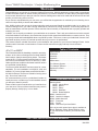
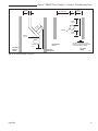
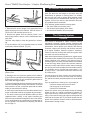
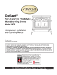
Encore®
Non-Catalytic / Catalytic
Woodburning Stove
Model 2040CE
Homeowner’s
Installation and
Operating Manual
For use in Europe
2425
Encore NC Cover
5/05
Safety Notice: If this appliance is not properly installed, operated and maintained, a house fire may result.
To reduce the risk of fire, follow the installation instructions. Failure to
follow instructions may result in property damage, bodily injury or even
death. Contact local building officials about restrictions and installation
inspection requirements in your area.
Do Not Discard This Manual: Retain for Future Use
30005552 7/11 Rev. 1
Encore® 2040CE Non-Catalytic / Catalytic Woodburning Stove
Welcome
Congratulations on your choice of a Vermont Castings Encore stove. With this purchase you have made a commitment
to make the hearth a place of warmth, beauty and comfort in your home. At MHSC, we share that joy and appreciation
for the hearth. We assure you that your cast-iron Vermont Castings stove has been made with the utmost care and will
provide you with many years of service.
As you become acquainted with your new stove, you will find that its appearance is matched by its functionality, due to
cast iron’s unique ability to absorb and radiate heat.
Also, MHSC products are among the cleanest-burning wood stoves and fireplaces available today. As an owner of a
Vermont Castings stove, you make a strong statement for pollution-free energy. However, clean burning depends on
both the manufacturer and the operator. Please read this manual carefully to understand how to properly operate and
maintain your stove.
At MHSC, we are equally committed to your satisfaction as a customer. That is why we maintain an exclusive network
of the finest dealers in the industry. Our dealers are chosen for their expertise and dedication to customer service. They
are factory-trained and knowledgeable about every MHSC product. Feel free to contact your Authorized Vermont Castings Dealer anytime you have a particular question about your stove or its performance.
This manual contains valuable instructions on the installation and operation of your Vermont Castings Encore. It also
contains useful information on maintenance. Please read the manual thoroughly and keep it as a reference.
Sincerely,
Table of Contents
All of Us at MHSC
This manual describes the installation, operation, and maintenance of the Vermont Castings Encore Model 2040CE
Non-Catalytic / Catalytic wood burning heater. This heater
meets the U.S. Environmental Protection Agency’s emission limits for wood heaters sold on or after July 1, 1990.
Under specific test conditions this heater has been shown
to heat 9.6kW (34,000 Btu/hr).
The Encore Model #2040CE has been tested to current
standards. The test standards are ANSI/UL-1482 and
ANSI/UL-737 for the United States, and EN13240:2001 +
A2:2004 for Europe. The Encore is listed for burning wood
only. Do not burn other fuels.
We recommend that you hire a professional installer to
install your stove, or to advise you on the installation should
you attempt to install it yourself.
Please read this entire manual before you install and use
your new stove. Failure to follow instructions may result in
property damage, bodily injury, or even death.
Specifications.........................................................3
Installation..............................................................4
Assembly..............................................................12
Operation..............................................................15
Maintenance.........................................................18
The Chimney System...........................................20
The Catalytic Element..........................................22
Replacement Parts...............................................24
Warranty...............................................................27
Installation Accessories
Warming Shelf
#0200 Classic Black
#0205 Biscuit
#0207 Ebony
#0201 Bordeaux
#0208 Brown Majolica
#3265* Outside Air Kit
#3185 Outside Air Adapter
#0336* Mobile Home Kit
#0127 Firescreen
FK26 Fan Kit
#3190 Connector Pipe Heat Shield
A line of porcelain enamel stove pipe is available in
Biscuit, Bordeaux, Ebony, Brown Majolica colors.
*If you order #3265 or #0336, you must also need
#3185.
Save These Instructions for Future Reference
30005552
Encore® 2040CE Non-Catalytic / Catalytic Woodburning Stove
Specifications
Encore Model 2040CE
Nominal heat out put.........7.8 - 8.0 kW (34,000 BTU/hr)1
Minimum flue draught......................... 12 Pa (0.048” WG)
Mean flue gas temp................................. 339° C (642° F)
Efficiency (Space heating) with Catalyst................ 75.9%
Efficiency (Space heating) w/o Catalyst................. 72.9%
Area heated...................... Up to 167 sq. m (1800 sq. ft.)1
Fuel size/type........................457-559 mm (18-22”) wood
Fuel capacity.............................................. 22 kg (50 lbs)
Flue mass gas flow................................................ 6.6 g/s
CO Emissions (@ 13% O2) ..w/Cat. 0.09% w/o Cat. 0.42
Loading........................................................Front and top
Chimney connector:
for 8” flue collar...........................203 mm (8”) diameter
for 6” flue collar...........................152 mm (6”) diameter
Chimney flue size:
for 8” flue collar.......................... 203 mm (8”) minimum
for 6” flue collar.......................... 152 mm (6”) minimum
Flue exit position...........................Reversible, top or rear
Primary air...... Manually set, thermostatically maintained
Secondary air..................................Fixed, self-regulating
Ash handling system........................ Removable ash pan
Glass panel.............................High-temperature ceramic
Weight................................................... 215 kg (475 lbs.)
Width (leg-to-leg).........................................685 mm (27”)
Depth (leg-to-leg)........................................380 mm (15”)
Height to top of flue collar............................635 mm (25”)
1. This value can vary depending on how the stove is
operated, the type and moisture content of the fuel used,
as well as the design, construction and climatic location
of your home. Figures shown are based on nominal fuel
consumption obtained under laboratory conditions and on
average efficiencies.
Drawings Not to Scale
578 mm
(226M”)
95 mm
(36M”)
44 mm
(16M”)
686 mm (27”)
470 mm
(1856O”)
565 mm
(2256M”)
394 mm
(1556O”)
635 mm
(25”)
Top exit
flue collar
height
654 mm
(256M”)
184 mm
(756M”)
686 mm (27”)
127 mm
(5”)
73 mm (2(6”)
603 mm
(236M")
381 mm
(15”)
Fig. 1 Encore 2040CE dimensions.
30005552
Encore 2N1
dimensions CE
Encore® 2040CE Non-Catalytic / Catalytic Woodburning Stove
Installation
safety NOTICE: IF YOUR ENCORE IS NOT PROPERLY
INSTALLED, A HOUSE FIRE MAY RESULT. TO REDUCE
THE RISK OF FIRE, FOLLOW THE INSTALLATION INSTRUCTIONS. CONTACT LOCAL BUILDING OR FIRE
OFFICIALS ABOUT RESTRICTIONS AND INSTALLATION INSPECTION REQUIREMENTS IN YOUR AREA.
Before you begin an installation, be sure that:
• Your stove and chimney connector will be far enough
from combustible materials to meet all clearance
requirements.
• The floor protector is large enough and is constructed
properly to meet all requirements.
• You have all necessary permits from local authorities.
Your local building official is the final authority for approving your installation as safe and determining that it meets
local and state codes.
The metal label permanently attached to the back of
every Vermont Castings’ stove indicates the stove has
been tested to current standards. The test standard is
EN13240:2001 + A2:2004 for Europe. Clearance and
installation information also is printed on the label. When
the stove is installed according to the information both on
the label and in this manual, local authorities in most cases
will accept the label as evidence that the installation meets
codes and can be approved.
However, codes vary in different countries. Before starting
the installation, review your plans with the local building
authority. Your local dealer can provide any additional
information needed.
Outside Air
In some modern, super-insulated homes, there is inadequate air for combustion because of insufficient air infiltration into the building. Such air enters a home through
unsealed cracks and openings. Exhaust fans for kitchen
or bath can compete with the stove for available air and
compound the problem.
When poor draft is caused by a low infiltration rate, opening a ground floor window on the windward side of the
house and in the vicinity of the stove will usually alleviate
the problem.
For appliances with power outputs above 5 kW, a permanently open air vent is required by Section 2 of Document
J. Air inlet grilles should be positioned so that they will not
be blocked. Refer to local and national codes for recommended configurations.
Pressure variations within the house do not affect a stove
equipped with an outside air supply, and improved stove
performance often results. An Outside Air Adapter Kit for
the Encore is available from your local Vermont Castings
dealer.
Chimney Height
Altitude affects chimney performance. When using a 6”
flue collar on the Encore, refer to Figure 2 for suggested
chimney heights at various altitudes. Chimney height
should be measured from the flue collar to the top of the
chimney. The recommended minimum chimney height is
4.9 m (16’).
Important: Failure to follow these installation instructions may result in a dangerous
situation, including a chimney or house fire.
Follow all instructions exactly, and do not
allow makeshift compromises to endanger
property and personal safety.
25
Height
all local regulations, including those referring to national and European standards, need to be complied
with when installing this stove.
30
20
15
0
ST491
2000
4000
6000
8000
10000
12000
Altitude
Fig. 2 Chimney height requirements for Encore when equipped
with a 152 mm (6”) chimney.
ST491
Defiant
chimney height
11/2/00 djt
30005552
Encore® 2040CE Non-Catalytic / Catalytic Woodburning Stove
What Kind of Chimney to Use
Prefabricated Chimneys
You must connect the Encore to a code-approved masonry
chimney with a flue liner, to a relined masonry chimney that
meets local codes, or to a prefabricated metal chimney.
(Fig. 3) The chimney and chimney connector must be in
good condition and kept clean.
If you use an existing masonry chimney, it must be inspected to ensure it is in a safe condition before the stove is
installed. Your local professional chimney sweep, building
inspector, or fire department official will be able to inspect
the chimney or provide a referral to someone who can.
These should be an internal diameter of 150 mm (6”) and
be of the twin wall insulated construction that has been
approved for solid fuel use (e.g. Rite Vent ICS of ICID
Lite Chimney Systems). Diameters over 200 mm (8”) are
not recommended due to the large cross-section causing
excessive cooling of the flue gases.
The flue and chimney design must meet requirement J2,
Part J of the building regulations 2000 (Combustion Appliances and Fuel Storage Systems).
An Encore with an 203 mm (8”) flue collar is approved for
venting into a masonry chimney with a nominal flue size
of 203 x 203 mm (8” x 8”) or 203 x 305 mm ( 8” x 12”), and
into a round flue with nominal flue size of 203 mm (8”).
An Encore with a 152 mm (6”) flue collar is approved for
venting into a masonry chimney with a nominal flue size of
203 x 203 mm (8” x 8”), and into a round flue with nominal
flue of 152 mm (6”).
A prefabricated doublewall insulated chimney
DO NOT CONNECT THIS UNIT TO A CHIMNEY FLUE
SERVING ANOTHER APPLIANCE.
Chimney Size
NOTE: When installed with a 6” flue collar, the Encore
may not be operated with the front doors open.
Whatever the flue collar size, an Encore may be vented
into larger chimneys as well. However, chimneys with
liners larger than 203 x 305 mm (8” x 12”) may experience
rapid cooling of smoke and reduction in draft, especially if
the chimneys are located outside the home. These large
chimneys may need to be insulated or have their flues
relined for proper stove performance.
A tile-lined
masonry
chimney
ST241
Fig. 3 Approved chimney types.
Masonry Chimneys
An inspection of the chimney
ST241 must confirm that it has a lining. Do not use an chimney
unlinedtypes
chimney. The chimney should
12/13/99 djt
have no cracks, loose mortar, other signs of deterioration,
and blockage. Repair any defects before the chimney is
used with your stove.
Unused openings in an existing masonry chimney must
be sealed with masonry to the thickness of the chimney
wall, and the chimney liner should be repaired. Openings
sealed with pie plates or wallpaper are a hazard and should
be sealed with mortar or refractory cement. In the event
of a chimney fire, flames and smoke may be forced out of
these unused thimbles.
The chimney should be thoroughly cleaned before use.
A newly-built masonry chimney must conform to the
standards of your local building code or, in the absence
of a local code, to a recognized national code. Masonry
chimneys must be lined, either with code-approved masonry or pre-cast refractory tiles, stainless steel pipe, or
a code-approved, “poured-in-place” liner. The chimney’s
clean-out door must seal tightly.
30005552
Accessories to help make the connection between stainless steel chimney liners and your Encore are available
through your local dealer.
Chimney Connector Guidelines
A chimney connector is the double-wall or single-wall pipe
that connects the stove to the chimney. The chimney itself
is the masonry or prefabricated structure that encloses the
flue. Chimney connectors are used only to connect the
stove to the chimney, as in Figure 5.
Connecting Flue Pipes
Connector pipes should meet the requirements of the building regulations. This can be achieved by the use connecting
fluepipes included in the following categories:
a)Vitreous enamelled steel pipe complying with BS 6999:
1989 (1996);
b)Pipes made from stainless steel as descirbed in BS EN
1008-1:1995 grades 1.4401, 1.4404, 1.4432 or 1.4436 with
flue wall thickness of at least 1 mm;
c)Mild steel fluepipes complying with BS 1449: Part 1:
1991, with a flue wall thickness of at least 3 mm;
d)Cast iron fluepipes complying with BS 41: 1973
(1998).
Encore® 2040CE Non-Catalytic / Catalytic Woodburning Stove
Flue Pipes with a spigot and socket joint should be fitted
with the socket facing upwards, to contain condensates
and moisture within the flue. Joints should be made gas
tight using proprietary jointing accessories, or, where appropriate, by packing joint with noncombustible rope and
fire cement.
Double-wall connectors must be tested and listed for use
with solid-fuel burning appliances. Single-wall connectors
should be made of 24 gauge or heavier steel. Do not use
galvanized connector; it cannot withstand the high temperatures that can be reached by smoke and exhaust gases,
and may release toxic fumes under high heat. The connector may be 152 mm (6”) or 203 mm (8”) in diameter.
If possible, do not pass the chimney connector through
a combustible wall or ceiling. If passage through a combustible wall is unavoidable, refer to the section on Wall
Pass-Throughs. Do not pass the connector through an
attic, a closet or similar concealed space. The whole connector should be exposed and accessible for inspection
and cleaning.
In horizontal runs of chimney connector, maintain a distance of 610 mm (24”) from the ceiling. Keep it as short and
direct as possible, with no more than two 90° turns. Slope
horizontal runs of connector upward 6 mm per metere
(1/4” per foot) going from the stove toward the chimney.
The recommended maximum length of a horizontal run
is 914 mm (36”), and the total length should be no longer
than 2.4 m (8’). In cathedral ceiling installations, extend
the prefabricated chimney downward to within 2.4 m (8’)
of the stove.
Wear gloves and protective eyewear when drilling, cutting or joining sections of chimney connector.
Double-wall Chimney Connectors
Information on assembling and installing double-wall connectors is provided by the manufacturer of the double-wall
pipe. Follow the manufacturer’s instructions exactly as
you assemble the connector and attach it to the stove
and chimney. Using chimneys and connectors from the
same manufacturer makes the assembly and installation
straightforward.
NOTE: For installations using double-wall connectors,
minimum clearances must conform to the listed clearances
in the clearance chart on Page 14.
If the Encore is equipped with the 203 mm (8”) flue collar,
an oval-to-round adapter will be needed. Double-wall ovalto-round adapters are available from some manufacturers.
Your local dealer can help you select the right connector.
Single-wall Chimney Connectors
• Begin assembly at the flue collar of the stove. Insert the
•
•
•
first crimped end into the stove’s flue collar, and keep
each crimped end pointing toward the stove. (Fig. 4)
Using the holes in the flue collar as guides, drill 3 mm
(1/8”) holes in the bottom of the first section of chimney
connector and secure it to the flue collar with three #10
x 1/2” sheet metal screws.
Secure each joint between sections of chimney connector, including telescoping
joints, with at least three (3)
sheet metal screws. The
pre-drilled holes in the top
of each section of chimney
connector serve as guides
when you drill 3 mm (1/8)
holes in the bottom of the
next section.
Secure the chimney connector to the chimney. Instructions for various installations Fig. 4 the crimped end
of the connector points
follow.
ST242
connector
towardChimney
stove.
12/13/99 djt
Be sure the installed stove
and chimney connector are
correct distances from nearby combustible materials.
NOTE: Special slip pipes and thimble sleeves that form
telescoping joints between sections of chimney connector
are available to simplify installations. They often eliminate
the need to cut individual connector sections. Consult your
local dealer about these special pieces.
Securing the Single-wall Connector to a
Prefabricated Chimney
Follow the installation instructions of the chimney manufacturer exactly as you install the chimney. The manufacturer
of the chimney will supply the accessories to support the
chimney, either from the roof of the house, at the ceiling of
the room where the stove is installed, or from an exterior
wall.
Special adapters are available from your local dealer to
make the connection between the prefabricated chimney
and the chimney connector. The top of such adapters
attaches directly to the chimney or to the chimney’s ceiling support package, while the bottom of the adapter is
screwed to the chimney connector.
These adapters are designed so the top end will fit outside
the inner wall of the chimney, and the bottom end will fit
inside the first section of chimney connector. When assembled in this way, any soot or creosote falling from the
inner walls of the chimney will stay inside the chimney
connector.
30005552
Encore® 2040CE Non-Catalytic / Catalytic Woodburning Stove
Chimney
Flue
Elbow
Thimble Sleeve
Flue Liner
Chimney Connector
Keep
sleeve
end flush
with flue
tile
Slip Pipe
Standard
Connector
Oval to
Round Adapter
Flue
Thimble
ST243
Flue Collar
Fig. 6 The thimble, made of either ceramic or metal, must be
cemented securely in place.
ST492
Fig. 5 Chimney connection in a freestanding masonry installation.
Securing
ST492
Defiant
the Single-wall
freestanding Connector
installation
Masonry
Chimney
11/00
to a
Both freestanding masonry chimneys and fireplace masonry
chimneys may be used for your installation.
Freestanding Installations
If the chimney connector must pass through a combustible
wall to reach the chimney, follow the recommendations in
the Wall Pass-Through section that follows.
The opening through the chimney wall to the flue (the
“breech”) must be lined with either a ceramic or metal
cylinder, called the “thimble”, which is cemented securely
in place. Most chimney breeches incorporate thimbles, but
the fit must be snug and the joint between the thimble and
the chimney wall must be cemented firmly.
A special piece called the “thimble sleeve,” slightly smaller
in diameter than standard connectors and most thimbles,
will facilitate the removal of the chimney connector system
for inspection and cleaning. Thimble sleeves should be
available from your local dealer.
To install a thimble sleeve, slide it into the breech until it is
flush with the inner flue wall. Do not extend it into the actual
flue passage, as this could interfere with the draft.
The thimble sleeve should protrude 1-2” (25-50mm) into
the room. (Fig. 6) Use furnace cement and thin gasketing to seal the sleeve in place in the thimble. Secure the
chimney connector to the outer end of the sleeve with sheet
metal screws.
30005552
Without a thimble, a suitable length of chimney connector
can be extended through the breech to the inner face of
the flue liner, and cemented securely in place. Additional
ST243
pieces of connector
are then attached with sheet metal
thinble connection
12/13/99 djt
screws.
Fireplace Installations
The chimney connector may be connected to the chimney
above the fireplace opening or through the fireplace.
Above the Fireplace
The Encore may be connected to a chimney above a
fireplace opening. (Fig. 7) In such installations, the stove
is positioned on the hearth in front of the fireplace and the
chimney connector rises from the stove top and then angles
ninety degrees back into the chimney. The chimney liner
should extend to the point at which the chimney connector
enters the chimney.
If the chimney connector from your installation enters the
chimney above a fireplace, follow all the guidelines mentioned above for freestanding installations. In addition, give
special consideration to the following points:
• Check the clearance between the stove and the chimney
•
•
connector, and any combustible trim or the mantel. Use
the necessary combination of mantel, trim, and connector heat shields to achieve the required clearances.
Check the clearance between the chimney connector
and the ceiling. If no heat shields are used, the clearance should be at least 610 mm (24”).
The fireplace damper must be sealed to prevent room
air from escaping up the flue. However, it must be
possible to re-open the damper to inspect or clean the
chimney.
Encore® 2040CE Non-Catalytic / Catalytic Woodburning Stove
Check These
Clearances
*
Flexible Connector
*
* Check These
Clearances
Mantel Shield
Fireplace Adapter
Kit “Positive Connection”
Mantel
DEFIANT
Seal
This Off
ST244a
Fig. 7 In this installation, the chimney connector attaches to
the chimney above the fireplace opening.
ST244
Through
the Fireplace
Plymouth
fplcheight
over mantel
If your fireplace opening
is at least 737 mm (29"), you
12/99
may install an Encore through the opening using a “positive
connection” kit, available from your local dealer. These positive connection kits ensure a tight fit between the stove flue
collar and the chimney flue. (Fig. 8)
Fireplace installations, whether connected to the flue above
or through the fireplace opening, have special clearance
requirements to adjacent trim and the mantel. You’ll find the
required safe clearances for Encore fireplace installations
on Page 11.
Floor protection requirements also apply to fireplace installations. This information is on Page 9.
Wall Pass-Throughs
Whenever possible, design your installation so the connector does not pass through a combustible wall. If you are
considering a wall pass-through in your installation, check
with your building inspector before you begin. Also, check
with the chimney connector manufacturer for any specific
requirements.
Accessories are available for use as wall pass-throughs.
If using one of these, make sure it has been tested and
listed for use as a wall pass-through.
ST245
Fig. 8 In this installation, the chimney connector enters the
firepalce opening and then connects to the chimney.
ST245
Figure 9 shows one method
of passing a connector through
a wall. All combustible fireplace
material in the wall is cut away to
flex connector
provide the required 457
mm (18”) clearance for the con12/99
nector. The resulting space must remain empty. A flushmounted sheet metal cover may be used on one side only.
If covers must be used on both sides, each cover must be
mounted on noncombustible spacers at least 25 mm (1”)
clear of the wall.
Your local dealer or your local building inspector can provide
details for other approved methods of passing a chimney
connector through a combustible wall in your area.
Do not connect an ENCORE to any air distribution duct or system.
457 mm (18”) clear
space all around the
pipe
T
ST494
Fig. 9 An approved wall pass-through.
ST494
steel
wall pass thru
11/00
30005552
Encore® 2040CE Non-Catalytic / Catalytic Woodburning Stove
Hearths
This appliance must be installed on to hearth that meets
the requirements of Part J of the Building Regulations 2000
(Combustion Appliances and Fuel Storage Systems). This
can be achieved by ensuring that the hearth is constructed
and sized in accordance with the guidelines included in section 2 of approved document ‘J’. The size and clearances
of the hearth are as follows:
The constructed hearth should be constructed in accordance with the recommendations in document J, and
should be of minimum width 840 mm and minimum depth
840 mm (if a free standing hearth b) above) or a minimum
projection of 150 mm from the jamb (if a recessed hearth
a) above).
Wood framing requires protection from radiant heat
ST247e
Fig. 11 Combustible supporting timbers may lie beneath fireplace hearths, requiring additional floor protection.
Unless the stove hearth is completely noncombustible,
the bottom heat shield
should be installed to
Costructional Hearth
Dimensions as below
provide radiant protection for framing which
may be below the
hearth. (Fig. 11)
At least 150 mm
or to a suitable
heat resistant wall
ST247
Rear exit floor dgrm
Appliance
12/14/99 djt
Appliance
Doors
Doors
Hearth Surface
Free of Combustible Material
At least
150 mm
Perimeter should be
clearly marked e.g.
edge of superimposed
hearth
At least
300 mm
a) Fireplace recess
Perimeter should be
clearly marked e.g.
edge of superimposed
hearth
b) Free standing
ST912
Fig. 10 Noncombustible hearth surface dimensions.
Floor Protection for Fireplace Installations
Do not assume that your fireplace hearth is completely
noncombustible.
Many fireplace hearths do not meet the “completely noncombustible” requirement because the brick or concrete in
front of the fireplace opening is supported by heavy wood
framing. (Fig. 11) Because heat passes through brick or
concrete readily, it can easily pass through to the wood.
As a result, such fireplace hearths can be a fire hazard and
are considered a combustible floor.
Keep in mind, also, that many raised hearths will extend
less than the required clearance from the front of the heater
when it is installed. In such cases, sufficient floor protection
as described above must be added in front of the hearth to
satisfy the minimum floor protector requirement from the
front of the stove: 406 mm (16”) from the front.
30005552
Hearth rugs do not satisfy the requirements for floor protection.
Keep the Stove a Safe Distance
from Surrounding Materials
Both a stove and its chimney connector radiate heat in all
directions when operating, and dangerous overheating
of nearby combustible materials can occur if they are too
close to the heat. A safe installation requires that adequate
clearance be maintained between the hot stove and its
connector and nearby combustibles.
Clearance is the distance between either your stove (measured from the bottom edge of the stove’s top plate) or
chimney connector, and nearby walls, floors, the ceiling,
and any other fixed combustible surface. Your stove has
special clearance requirements that have been established
after careful research and testing to both US and European
standards. These clearance requirements must be strictly
observed.
Encore® 2040CE Non-Catalytic / Catalytic Woodburning Stove
In addition, furnishings and other combustible materials
must be kept away from the stove as well. In general, a
distance of 1219 mm (48”) must be maintained between
the stove and moveable combustible items such as drying clothes, furniture, newspapers, firewood, etc. Keeping
those clearance areas empty assures that nearby surfaces
and objects will not overheat.
Safe Ways to Reduce Clearances
Clearances
As with any solid fuel heating stove, extremely high
surface temperatures can occur, particularly in the
event of uncontrolled operation, e.g. if the doors are
inadvertently left open. It is crucial that sufficient clearances are allowed to any combustible surfaces, e.g.
wooden mantels or lintels, and to timber framed (studded) walls even if they are faced with noncombustible
board. Detailed information on fireplace and hearth
construction is provided in section 2 of Document
J, all installations must comply with these requirements or with the relevant National or local building
standards.
Clearances to timber framed (studded) walls are included
below. There are no specific minimum clearances to solid
noncombustible surfaces (e.g. the sides and rear of Inglenook fire openings constructed from solid masonry) other
than to allow safe access to the controls of the stove. For
this reason minimum side clearances of 125 mm, and a
minimum rear clearance of 50 mm are recommended.
Summary of Clearances
Minimum recommended side clearances to noncombustible surfaces 125 mm (5”).
Minimum rear clearance from combustible walls (e.g.
timber framed or studded walls) 254 mm (10”) measured from the rear edge of the stove top. (Fig. 12, B)
Minimum side clearance from combustible walls 483
mm (19”) measured from the side edge of the stove
top. (Fig. 12, A)
Minimum distance from stove to movable combustible
materials (e.g. furniture, drying clothes, etc.) 1220 mm
(48”).
B
A
ST486a
Fig. 12 Minimum clearances.
Connecting FlueST486a
Pipe - Clearances
Single wall connecting
fluepipesEU
can reach extremely high
Defiant
temperatures; therefore,
clearances from the connecting
Clearance
fluepipe (chimney connector) must comply with the requireDiagrams
ments of Part J of Building Regulations 2000 (Combus10/06
tion Appliances and Fuel
Storage Systems). This can be
achieved by following the recommendations of Approved
Document ‘J’. These are as shown in Figure 13.
Minimum recommended rear clearance to noncombustible surfaces 50 mm (2”).
NOTE: The minimum thickness of solid noncombustible
materials is specified in section 2 of Document ‘J’, in relation to the clearance of the appliance from the surface.
As a general rule, the thickness of solid noncombustible
material forming the recess of a fireplace is a minimum of
200 mm.
10
30005552
Encore® 2040CE Non-Catalytic / Catalytic Woodburning Stove
at least
3xD
at least 3 x D
D
at least
1.5 x D
D
at
3 lea
x st
D
at least
1.5 x D
Fluepipe
at least
1.5 x D
at least
1.5 x D
at least 1.5
xD
Elevation
Without
Shield
Plan Without
Shield
Elevation
With Shield
Air space of at least 12 mm
between noncombustible shield
and combustible material
Plan With
Shield
ST911
Fig. 13 Connecting fluepipe clearances.
34
FLUEPIPECLEARANCES
30005552
11
Encore® 2040CE Non-Catalytic / Catalytic Woodburning Stove
Assembly
Set Up Your Stove
Cast iron stoves are heavy, and it will take two to four people
to move your Encore into position.
Wipe the protective
coating of oil from the
griddle with a clean
dry rag or a paper
towel.
Install the handle on
the griddle. First,
place the griddle upST516
side down at the edge
of a flat surface and Fig. 14 Attach the griddle handle.
assemble the handle as shown.
ST516
With the handle pointing 45° from its final position, tighten
Attach
the nut as far as possible with the pliers. Move the handle to
griddle handle
its final position while still holding the nut with the pliers.
11/17/00 djt
Storing the Handle
Use the removable handle to open or close the doors. After
using it, remove the handle so it will not get hot. Store the
handle in the handle holder installed behind the right front
leg. (Fig. 15)
Bottom Heat Shield
ST857a
Fig. 16 Attach the bottom heat shield.
Adjust the Leg Levellers
ST857
Lift the stove slightly so there is no weight on the leg
abottom heat shield
while making the adjustment.
12/05
1/10 (If necessary)
Reverse the Flue Collar
Reverse the flue collar by removing the two screws that
attach it to the back of the stove. Be sure the gasket around
the flue collar opening is in position when you screw the
collar back onto the stove.
Adjust Air Deflector
If you have the optional fan kit, you may decide to adjust the
air deflector to blow heat across the top of your stove. (Fig.
17) Loosen the two (2) screws on each side and raise or
lower the deflector. After adjustment, tighten the screws.
Bottom Heat Shield
Door Handle Holder
Leg Bolt and Washer
Attach Flue Collar Heat Shield
ST564
Fig. 15 Handle holder and heat shield positions.
Install the Bottom
ST564Heat Shield
NOTE: The Bottom Heat
Shield isholder
required in most inhandle
stallations. Refer to Floor Protection, Page 9, for further
12/13/00
details.
1. Loosen the four 1/4-20 hex head bolts from the corners
of the ash drop on the stove bottom.
2. Align the bottom heat shield holes with the four bolts.
The outside air cutout hole should be toward the rear
of the stove. The unpainted side must face up towards
the stove.
3. Pass all four bolts through the large end of the keyholes
and then pulling the shield forward to engage the smaller
ends of the keyhole slots. (Fig. 16)
4. Attach the heat shield sides by passing the slots over
the bolt heads. Tighten the hex head bolts.
12
WARNING: The flue collar heat shield must be attached
to the Encore stove. Use four #10 sheet metal screws
supplied to secure the flue collar heat shield to the rear of
the stove. (Fig. 17)
Attach the Damper Handle
Use the 1/4” -20 x 3” screw to attach the damper handle
to the damper stub on the left side.
Attach the Primary Air Thermostat Handle
The primary air thermostat handle is the smaller of the
two black handles. Secure the handle to the stub on the
right side of the stove with an 8-32 x 2” slot head machine
screw. (Fig. 18)
30005552
Encore® 2040CE Non-Catalytic / Catalytic Woodburning Stove
Fan Kit Installation
Air Deflector
Air Deflector
Sheet
Metal
Screws
Flue Collar
Heat Shield
Sheet
Metal
Screws
ST1180
Fig. 17 Install flue collar heat shield.
WARNING: The flue collar heat shield must be installed
ST1180
in all vertical installations. The flue
collar heat shield is
heatposition.
shield
not used when the flue collar is influe
thecollar
rear exit
1. Attach the fan assembly at the bottom edge of the inner back with two (2) 1/4-20 x 3/4” hex head screws.
2. Attach snapstat to the mounting holes on the underside
of the bottom with two (2) 1/4-20 pan head screws.
3. Attach the rheostat holder (provided with the stove)
under the right front wing of the bottom heat shield with
two (2) #10 sheet metal screws.
4. Attach the rheostat to its holder by inserting the rheostat control shaft through the holder hole. Install the
retaining ring and rheostat knob onto the shaft.
5. Secure the rheostat cable to the underside of the bottom heat shield using the wire tie provided and the
hole at the right rear edge of the heat shield.
6. Fan will not operate until stove reaches approximately
43° C (109° F).
7. Plug blower cord into a grounded outlet. Do not remove ground prong from plug. Route power cord to
avoid heat from the stove or other damage. Do not
route cord under or in front of appliance.
Hole for Wire
Tie to Secure
Cable
ST635
Rheostat
Knob
Fig. 18 Attach the thermostat handle.
Assemble the Removable
Insert Handle
ST635
Encore
The ceramic removable
insert handle opens and closes
the front doors. Remove
afterthermostat
each use, and store it in
Install
the handle holder behind
the right front leg. Assemble
handle
the handle by passing the
3³⁄₈" screw through the ceramic
2/01
shaft and into the bright metal nub. (Fig. 19) Tighten carefully until snug.
Rheostat
Holder
Rheostat
Snapstat
Screws
ST848
Fig. 20 Fan installation (Kit # 2767).
34
FANINSTALL
ST540
Fig. 19 Assemble the front door handle.
30005552
13
ST540
Encore® 2040CE Non-Catalytic / Catalytic Woodburning Stove
Installing or Removing Catalyst
1. Remove the access cover by gently lifting up and pulling out from the bottom edge. (Fig. 21)
2. Remove the inner cover by pulling it straight out. (Fig.
22)
3. Remove the catalyst by gently pulling it straight out.
(Fig. 23) Place the catalyst where the catalyst’s ceramic components will not be damaged.
Access
Cover
Remove Catalyst
ST1189
Fig. 23 Remove catalyst.
ST1189
remove catalyst
ST1187
Fig. 21 Remove access cover.
Inner Cover
ST1187
remove access cover
ST1188
Fig. 22 Remove inner cover.
ST1188
remove inner cover
14
30005552
Encore® 2040CE Non-Catalytic / Catalytic Woodburning Stove
Operation
The Encore Controls
Two controls regulate the performance of the Encore: a
primary air control supplies oxygen for the fire, and a
damper directs air flow within the stove to activate and
deactivate the catalytic combustor.
Low Heat
Symbols cast into the stove are reminders of the correct
directions for opening and closing the controls. The symbols assume that you are facing the front of the stove.
Damper Handle
Griddle Handle
Door Handle
High Heat
Air Control
Lever
ST637
Fig. 25 The handle may be positioned anywhere between the
two extremes for different heat levels.
Door Handle
Holder (Behind leg)
Ashdoor
Handle
Andirons
ST636
Fig. 24 The Encore controls are conveniently located and
easy to operate.
A Single Air
Control Regulates
ST633
Heat Output
and Burn Time
Encore
The primary air control
lever, located on the right side of
controls
the stove, controls the2/01
amount of incoming air for starting,
maintaining, and reviving a fire.
More air entering the stove makes the fire burn hotter and
faster, while less air prolongs the burn at a lower heat level.
High and low settings appear in Figure 25.
For the greatest air supply and maximum heat output (but
the shortest burn time), move the lever toward the front
of the stove. For a fire that will last longer with less heat,
move the lever toward the rear of the stove.
The Encore’s air control system also features an automatic
thermostat to ensure an even heat output at whatever
manual setting you select. The thermostat senses the
heating and cooling of the stove surface and adjusts the
air shutter accordingly.
A Damper Directs Air Flow
Within the Stove
The damper handle on the left side of the stove operates
the damper to direct air flow within the stove.
The damper is open when the handle points to the rear,
enabling smoke to pass directly into the chimney. The
30005552
damper must be open when starting or reviving a fire, and
whenever the griddle or doors are opened.
The damper is closed when the handle points forward.
Smoke travels through the non-catalytic combustion system where it can be further burned, before passing up the
chimney. (Fig. 26)
ST637
encore
The damper should always
be either fully open or fully
closed. There are no intermediate positions. When
closing the damper, be
sure to
pull firmly enough to
Air
control
snap the handle into the locked position.
Damper Positions 2/01
Open
(Updraft Mode)
Closed
(High Efficiency
Mode)
ST638
Fig. 26 The damper is either open or closed. There are no
intermediate positions.
High-Efficiency Wood Burning
with Catalytic Combustion
ST638
An Encore leaves the factory
with the combustor packaged
Encore
separately.
In the United States, it isdamper
against the law control
to operate this
wood heater in a manner inconsistent with operating instructions in this manual. 2/01
The components of the catalytic
15
Encore® 2040CE Non-Catalytic / Catalytic Woodburning Stove
combustion system in your Encore work together to produce optimum conditions for secondary combustion.
When the damper is closed, smoke travels through the catalytic element, which causes ignition of smoke at temperatures of 260°-315°C (500°-600° F), half the temperature
normally required for unaided secondary combustion.
The catalytic element is a ceramic “honeycomb” coated
with the catalytic material. The element is located in the
secondary combustion chamber, molded from a special
high-temperature insulating refractory material. The
chamber provides the correct environment necessary for
secondary combustion of the fuel (smoke).
Closing the damper exposes the smoke to the combustor.
If the combustor is at least 315°C (600°F), it will begin to
burn the smoke.
use a full load of dry slab wood or scrap wood. For long
burns, use a mix of dry and moderately dry wood.
Two Ways to Add Fuel
The Encore’s griddle lifts for convenient top-loading of logs,
and is the easiest way to add fuel. (Fig. 27)
However, the front doors open as well for adding an occasional log to a fire. If the stove is equipped with 8” (203
mm) stove pipe, the front doors may be opened (or even
removed) and the optional Encore spark screen placed
in the opening for open-fire viewing. The Encore is not
approved for operation with the front doors open if
equipped with a 152 mm (6”) chimney connector or
chimney.
Closing the stove damper may also reduce the draft, so
to avoid putting out the fire or deactivating the combustor,
close the damper only when a fire is well-established and
the chimney is thoroughly warmed. When starting a fire,
wait until the fire is well established and there is an ember
bed of at least 75 - 100 mm (3-4 inches) before closing
the damper.
Never kindle a fire with colored paper or paper that has
colored ink or a glossy surface, and never burn treated
wood, garbage, solvents, or trash. All of these may poison
the catalyst and prevent it from operating properly. Never
burn cardboard or loose paper except for kindling purposes.
Never burn coal; doing so can produce soot or large flakes
of char or fly ash that can coat the combustor and cause
smoke to spill into the room. Coal smoke also can poison
the catalyst so that it won’t operate properly.
In general, the fire must be sufficiently well-established to
ensure that catalytic activity is initiated. When first starting a
fire, a medium- to high- firing rate must be maintained until
the stove, catalyst, and fuel are all stabilized at the proper
operating temperatures, and the chimney is warmed.
Even though it is possible for the fire to get quite hot within
a few minutes after a fire is started, the combustor may
stop working or the fire may go out if the fire dies down
immediately as a result of the damper being closed. Once
the combustor starts working, heat generated by burning
the smoke will keep it working.
To determine whether the combustor is operating, observe
the amount of smoke leaving the chimney when the damper
is activated and when it is not. This procedure is described
on Page 22.
Avoid using a full load of very dry wood in the firebox. This
may result in continuous very high temperatures in the
secondary combustion area and damage the combustor.
Wood which has been split, and stored under cover for
more than 18 months may be considered very dry. If you
must burn extra-dry wood, mix it with greener wood for a
longer fire and less stress on the combustor. Also, do not
16
Def
iant
ST521
Fig. 27 Top loading is the best way to add fuel during regular
use. Front loading
is useful for kindling a fire.
ST521
Intrepid
To open the front
doors, insert the handle into the door latch
stub and turn itloading
to the left and up. (Fig. 28)
11/00
To close them, always close the left door first. Turn the
handle in the right door to the left and up (to the open position) and close it. Finally, push on the door as you turn
the handle to the right and down. The doors will draw in
slightly, and the handle should offer some resistance as
you turn it to the closed position.
To reduce the risk of breaking the glass, avoid striking the
glass or slamming the doors.
When you are not using the door handle, store it in the
holder behind the right front leg of the stove. Be careful to
not drop the handle, since it is breakable.
Clockwise to
Open
Counterclockwise
to Close
ST544
Fig. 28 To open the front doors, turn the handle clockwise.
30005552
Encore® 2040CE Non-Catalytic / Catalytic Woodburning Stove
Caution: The Encore will be hot while in operation.
Keep children, clothing and furniture away. Contact
may cause skin burns.
DO NOT OVERFIRE THIS HEATER. Overfiring may
cause a house fire, or can result in permanent damage to the stove and to the catalytic combustor. If any
part of the Encore glows, you are overfiring.
You should remove ash before it reaches the top of the ash
pan. Check the level at least once a day. Every few days,
clear any ash from the outer edges of the firebox. Most of
the ash will fall through the grate. Slice or stir the ash with
a shovel or poker so that it falls through the grate slots.
IMPORTANT: Check the level of ash in the ash pan before
reloading the stove. If the ash level is close to the top edge
of the pan, empty the pan according to this procedure:
• Open the damper.
• Open the griddle or front doors, and use a shovel or
•
falling on the floor, do not tilt the ash pan forward.
If the stove is in operation, close the ash door while
•
•
Ash Disposal
•
• Remove the ash pan, making sure to keep it level.
• To keep the cover from sliding off and to keep ash from
poker to stir excess ash through the ash slots in the
grate down into the ash pan.
Close the griddle or doors, and unlatch the ash door. It
will pivot, swinging the ash pan out of the stove.
Slide the cover onto the pan, making sure it is securely
closed. (Fig. 29)
•
disposing of the ash.
Properly dispose of the ash in a metal container with a
tight-fitting lid. Store the container outdoors away from
all combustible material.
Return the ash pan to its original position in the stove,
and close and latch the ash door.
Do not operate the stove with the ash door open. This
will result in over-firing, and could cause damage to the
stove, void the warranty, or even lead to a house fire.
Empty the ash pan regularly, typically every one to three
days. The frequency will vary depending on how you operate your Encore: ash will accumulate faster at higher
heat outputs.
Remove ash frequently and place it outdoors in a metal
container with a tight-fitting lid. Place the closed container
of ash on a noncombustible floor or on the ground, well
away from all combustible materials, pending final disposal.
If the ash is disposed of by burial in soil or otherwise locally
dispersed, it should be kept in the closed container until all
cinders have thoroughly cooled.
You can use wood ash as a garden fertilizer.
CAUTION: Never use your household or shop vacuum
cleaner to remove ash from the stove; always remove and
dispose of the ash properly.
Open
Close
ST545
ST566
Fig. 29 Be sure the cover is securely attached before removing the ash pan.
ST566
Remove
Ashpan
12/00
30005552
Fig. 30 Turn the handle to the ash pan compartment clockwise to open and counterclockwise to close.
ST545
ashdoor
11/00
17
Encore® 2040CE Non-Catalytic / Catalytic Woodburning Stove
Maintenance
Keep Your Stove Looking New
and Working Its Best
Let the fire in the stove go out and allow the stove to cool
completely before beginning any maintenance procedure.
Care of the Cast Iron Surface
An occasional dusting with a dry rag will keep the painted
cast iron of your Encore looking new.
The stove’s paint can be touched up as needed. First, mask
the areas, such as enamelled parts, glass, or handles,
around the spot to be painted. Clean the spot with a wire
brush. Remove the griddle and set it aside. It is normal
for the griddle to darken after use. You can clean it with a
fine-bristle wire brush, or steel wool.
Then, touch up the stove with Vermont Castings’ high
temperature stove paint. Apply the paint sparingly; two light
coats of paint are better than a single heavy one.
Care of the Porcelain Enamel Surface
Use a dry or slightly damp rag or soft brush to remove spills
or stains. For difficult jobs that require a cleaning agent, use
only a kitchen appliance cleaner or polish recommended
for use on enamel surfaces.
If porcelain enamel becomes chipped or scratched during
use, apply “enamel epoxy” to the damaged area and allow
to dry. Once the epoxy has dried, sand the area to blend
with surrounding area and apply appropriate color touch-up
paint. Allow to dry completely before operating stove.
Cleaning the Glass
Most of the carbon deposits on the glass will burn off during hot fires.
Replace Broken Glass Immediately
Do not operate your stove if the glass in the doors is damaged.
If you need to replace the glass, use only the high temperature 5 mm ceramic glass supplied by Vermont Castings.
Do not use substitutes.
Removing the Glass
1. Remove the right and left door assemblies by raising
the door until the lower hinge pin clears its hole; then,
angle the door bottom slightly outward and pull down to
release the upper hinge pin. Place the doors face down
on a padded work surface. Be especially careful with
enamelled doors.
2. Remove the screws that hold the glass retainer clips in
place, and remove the clips.
3. Carefully lift the broken glass panel from the door.
Installing the Glass
Check the gasket around the window; it should be soft
and resilient so that the glass will seal properly against
the door. Replace the gasket if it has hardened or if it is
compressed.
1. Center the glass on the gasket.
2. Secure the glass on both doors with the retainer clips.
Tighten all screws. (Fig. 31)
3. Replace the doors on the stove.
4. Open and close the doors to check that they fit and work
properly. Adjust as necessary.
Right Door
Gasket
However, the ash residue that accumulates on the glass
surface should be removed regularly to prevent etching.
To clean the glass, follow this procedure:
Glass Panel
• Be sure the glass is completely cool.
• Clean the glass with water or a cleaner made especially
•
•
Retainer
Clips (4)
for this purpose. Do not use abrasive cleaners. Use
cleaning agents sparingly and be sure to keep them off
the outer surfaces of the stove.
Rinse the glass thoroughly.
Dry the glass completely.
ST854
Fig. 31 Exploded view of the glass assembly for the right door.
ST854
glass xview
7/05
18
30005552
Encore® 2040CE Non-Catalytic / Catalytic Woodburning Stove
Adjust the Damper as Needed
Roller
The tension on the Encore’s damper is adjustable to compensate for compression of the gasket that seals the damper
to the upper fireback. To adjust the damper:
1. Remove the griddle. Loosen the lock nut at the center
of the damper. (Fig. 32)
2. Turn the pressure screw approximately one half turn
clockwise with an Allen wrench provided with your
stove.
3. Tighten the lock nut. Prevent the pressure screw from
turning as you tighten the nut. Re-test the damper.
Pressure Adjusting Screw
Lock Nut
Set Screw
Flat Washer
Lock Nut
Allen
Wrench
Damper
Handle Stub
ST1154
Fig. 33 Rotate pawl and/or remove flat washer to adjust latch.
is raised and makes contact with the door frame. If this
procedure doesn’t solve the problem, replace the gasket.
ST1154
Instructions for gasket
replacement are given later in this
door pawl
section.
ST554
Fig. 32 Adjust the damper with the Allen wrench.
Tighten the Damper Handle as Needed
A handle on the left side of the stove controls the damper.
The handle attaches to the damper rod with a set screw. Periodically check the set screw and tighten as necessary.
How to Adjust the Door Latches
The front door of the stove should close securely to prevent
accidental opening and should close tightly to prevent air
from leaking into the fire chamber. The door handle will be
positioned vertically when the door is closed.
Over a period of time, the gasket around the door will
compress and the latch may need adjustment. To adjust
the handle, follow this procedure:
1. Remove and retain the
lock nut with a 9/16” wrench.
ST554
(Fig. 33)
Damper adjustment
2. Loosen the set screw with a 1/8” Allen wrench.
11/00 the lock nut. Tighten the
3. Rotate the pawl 180°. Replace
set screw.
4. Additional adjustment can be made by removing the flat
washer. Or any combination of washer removal and/or
pawl rotation.
Test the door seal. Close the door on a dollar bill and attempt to pull it free. If the bill is freed with little resistance,
the gasket isn’t snug enough at that spot. Continue to make
small adjustments until the setting is right.
If additional adjusting of the latch does not enable the door
to seal sufficiently in one area, try “adjusting” the gasket in
that area. Pack more cement or a smaller diameter gasket
into the channel beneath the gasket so the main gasket
30005552
Shoulder Screw
Replace the Stove Gaskets as Needed
Your Encore uses fiberglass rope gaskets to make a tight
seal between some parts. With use, particularly on moving
parts, gaskets can become brittle and compressed and can
begin to lose their effectiveness. These will need periodic
replacement.
The sizes of replaceable gasket are listed below, along
with their applications.
Gasket Diameter......And the Parts it Seals
5/16” The griddle to the stove top (wire reinforced gasket)
5/16” The damper to the upper fireback
3/8”
the front doors to the stove front; and the doors to each other.
3/8”
panel
The ash door to the front of the bottom 3/16”
The outer glass panes to the door
If you need to change a gasket, first obtain an appropriate replacement from your Vermont Castings’ Authorized
Dealer.
Wait until the fire is out and the stove has cooled. Be sure
to follow the standard safety procedure for working with
dusty materials: wear safety goggles and a dust mask.
The procedure for replacing gaskets is the same, regardless of the gasket location. Follow these steps:
1. Remove the existing gasket by grasping an end and
pulling firmly. (Fig. 34)
2. Use a wire brush or the tip of a screwdriver to clean
the channel of any remaining cement or bits of gasket.
Remove stubborn deposits of cement with a cold chisel if
necessary. (Fig. 34)
19
Encore® 2040CE Non-Catalytic / Catalytic Woodburning Stove
All Gasketed Construction Gaskets
ST560
Fig. 34 Remove gasket then clean channel with wire brush.
ST559
3. Determine the correctRemove
length of the appropriate-sized
gasket by laying it out in gasket
the channel. Allow an extra 1-2”
11/30/00
(25-50 mm), and mark the
spot todjtbe cut.
4. Remove the gasket from the channel, place it on a
wood cutting surface, and cut it at the marked spot with a
utility knife.
Twist the ends slightly to keep the gasket from unraveling.
5. Lay an unbroken 1/8” (3 mm) bead of silicone or cement
in the newly-cleaned channel. (Fig. 35)
et
ask
ve G ent
Sto Cem
ST561
Fig. 35 Lay a bead of gasket silicone or cement then press
gasket in place.
6. Starting at one end, ST559
press the gasket into the channel.
Remove
(Fig. 35) Ensure a good joint
where the gasket meets before
gasket
trimming any excess. Do
not overlap the gasket ends or
leave ends with ragged11/30/00
edges. djt
7. Press the gasketed part firmly against its normal mating
surface to seat the gasket evenly in its channel. Close and
latch the door to do this, or tap other parts with the rubber
mallet (or hammer/block of wood).
8. Clean any excess cement from around the channel, then
let the cement that holds the new gasket dry thoroughly.
9. The stove’s doors may need adjustment after you have
regasketed them. Initially, it may require loosening the
latch to accommodate the new gasket; after a few weeks,
it may need tightening to compensate for compression of
the new gasket. The directions for adjusting the latches
are on Page 19.
20
Other gaskets form seals between all other non-moving
parts, but these are not subject to the same wear and
deterioration as gaskets on moving parts. It is unlikely
that you will ever need to replace these gaskets unless
the involved parts are disassembled and then put back
together. If this is the case, the job should be done only
by a qualified service technician.
5/16” diameter gasket seals the following parts:
• The lower fireback to the back panel
• The left and right air plates (inner sides)
• All connections between the stove plates.
The Chimney System
Creosote
Your Encore is designed to reduce creosote build-up
significantly. However, regular chimney inspection and
maintenance must still be performed. For safety, good stove
performance, and to protect your chimney and chimney
connector, inspect your chimney and chimney connector
on a regular schedule. Clean the system if necessary.
Failure to keep the chimney and connector system clean
can result in a serious chimney fire.
When wood is burned slowly, it produces tar, organic vapors
and moisture that combine to form creosote. The creosote
vapors condense in the relatively cool chimney flue of a
slow-burning fire. As a result, creosote residue accumulates
on the flue lining. When ignited, this creosote makes an
extremely hot fire within the flue system that can damage
the chimney and overheat adjacent combustible material.
If a significant layer of creosote has accumulated —1/8”
(3 mm) or more — it should be removed to reduce the risk
of a chimney fire.
You can never be too safe. Contact your local fire authority for information on what to do in the event of a chimney
fire, and have a clearly understood plan on how to handle
one.
If you do experience a chimney fire, act promptly to:
• Close the damper and air control lever.
• Get everyone out of the house.
• Call the Fire Department.
Inspect the system every two weeks during the heating
season as part of a regular maintenance schedule. To
inspect the chimney, let the stove cool completely. Then,
using a mirror and a strong light, sight up through the flue
collar into the chimney flue. If you cannot inspect the flue
system in this fashion, the stove must be disconnected to
provide better viewing access.
30005552
Encore® 2040CE Non-Catalytic / Catalytic Woodburning Stove
Clean the chimney using a brush the same size and shape
as the flue liner. Flexible fiberglass rods are used to run the
brush up and down the liner, causing any deposits to fall
to the bottom of the chimney where they can be removed
through the clean-out door.
Clean the chimney connector by disconnecting the sections, taking them outside, and removing any deposits
with a stiff wire brush. Reinstall the connector sections
after cleaning, being sure to secure the joints between
individual sections with sheet metal screws.
If you cannot inspect or clean the chimney yourself, contact your local Vermont Castings dealer or a professional
chimney sweep.
Maintenance Schedule
The Stove
The Chimney Connector
TWO WEEKS:
• Inspect the chimney connector and chimney. Clean if
necessary.
TWO MONTHS:
• Inspect the chimney and chimney connector. Pay
particular attention to the horizontal runs of chimney
connector, and the elbows. Clean the system if necessary.
Annual Spring Cleaning:
• Disassemble the chimney connector and take it outdoors
•
DAILY:
• Clear any ash build-up from around the air holes and
combustion flow path in the lower fireback.
• Ashes should be removed before they reach the top of
the ash pan. Check accumulation at least once a day.
• Keep the area around the stove clear of any combustible
materials such as wood, furniture or clothing.
TWO MONTHS:
• Check door handle to be sure it is working properly.
Gasketing becomes compressed after a period of time.
Adjust handle tightness if necessary.
• Check leg bolts and heat shield screws; tighten if necessary.
Annual Spring Cleaning:
• Check gasketing for wear, and replace if necessary.
• Remove ashes from the ash pan and replace with a
moisture absorbing material (such as kitty litter) to keep
the interior of the stove dry.
• Clean the dust from the inner sides of bottom, rear or
pipe heat shields if your stove is equipped with them.
Clean surfaces are better heat reflectors than dirty surfaces.
• Touch up the black paint.
• Inspect for and remove ash build-up behind the combustion package. This should be done in conjunction
with annual cleaning of the chimney connector. Inspect
the passage behind the combustion package (a mirror
will be helpful) and vacuum away ash using a flexible
vacuum hose inserted in the passage. (Fig. 36)
30005552
•
for inspection and cleaning. Replace weak sections of
connector.
Inspect the chimney for signs of deterioration. Repairs to
a masonry chimney should be made by a professional
mason. Replace damaged sections of prefabricated
chimney. Your local Vermont Castings dealer or a chimney sweep can help determine when replacement is
necessary.
Thoroughly clean the chimney.
Clean
out any
ash build
up
Remove these components
ST1162
Fig. 36 Inspect and clean out ash accumulation behind the
combustion system.
ST1162
ash clean out
21
Encore® 2040CE Non-Catalytic / Catalytic Woodburning Stove
The
Catalytic Element
This wood heater contains a catalytic combustor, which
needs periodic inspection and replacement for proper
operation. In the United States it is against the law to operate this wood heater in a manner inconsistent with the
operating instructions in this manual.
Under normal operating conditions, the catalytic combustor should remain active for two to six years (depending
on the amount of wood burned). However, it is important
to monitor the combustor periodically to ensure that it is
functioning properly, as well as to determine when it needs
to be replaced. A non-functioning combustor will result in
a loss of heating efficiency, and an increase in creosote
and emissions.
Once you have ruled out any other possible causes for a
decline in performance, inspect and clean the combustor
if necessary. Be sure to protect any surface you use for
setting the stove parts aside.
Inspecting the Combustor
Remove access door and inner fireback. Remove the
catalytic combustor by lifting and sliding it towards you.
(Fig. 37)
Catalyst
Inspection and Cleaning
Inspect the combustor for fly ash accumulation and physical damage three times per year. Clean the combustor as
needed.
The refractory package that houses the catalytic combustor
should be inspected for a buildup of fly ash and cleaned
if necessary. This may be done when you examine the
combustor.
When to Suspect a Combustor Problem
The best way to evaluate the performance of your Encore’s
combustor is to observe the amount of smoke leaving the
chimney — both when the combustor has “lighted-off” and
when it has not. Follow these steps:
• With a fire going and the combustor properly activated,
with the damper closed to route smoke through it as
described in the Operation Section, go outside and
observe the smoke leaving the chimney.
• Then, open the stove damper and once again check
the smoke leaving the chimney.
You should see significantly more smoke when the stove
damper is open and exhaust does not pass through the
combustor. However, be careful not to confuse smoke with
steam from wet wood. Steam dissipates in the air quickly;
smoke does not.
If this test indicates a problem, consider other possible factors as well, such as the weather or a change in the quality
of your fuel. In warm weather, draft is weaker than it is in
colder winter weather, and fires can burn sluggishly. Small,
hot fires are a good solution under these conditions.
Burning “green” (insufficiently seasoned) wood will result in
poorer performance than burning properly seasoned fuel.
You may have to run your stove hotter (more air) to achieve
acceptable performance using green or wet wood.
Also, consider any changes in your operating routine.
22
Inner Fireback
Access Door
ST1180
Fig. 37 Inspect the catalytic combustor.
To assure a long life for the combustor, it is recommended
to service the combustor
on a regular basis based on the
ST1180
amount of use. This procedure
takes about five (5) minutes
catalyst access
and requires no tools except for a vacuum if cleaning is
necessary.
Cleaning the Combustor
1. Check the combustor’s honeycomb-like element for a
buildup of fly ash. If any is evident, take the combustor
outside and clean it by blowing air gently through it. Do
not push anything through the honeycomb; do not use
compressed air to clear the passages. Such abrasion
can scrape the thin coating of platinum (the catalyst)
off the ceramic base, shortening the catalyst’s life and
reducing its effectiveness.
2. Inspect the element for damage or degradation. Although small hairline cracks will not affect performance,
the element should be essentially intact. If the element
is broken in pieces or has sections missing, it should be
replaced. Call your local Vermont Castings Authorized
Dealer for a replacement element.
30005552
Encore® 2040CE Non-Catalytic / Catalytic Woodburning Stove
3. If the element is in good condition and clean, re-install
it in the stove and replace the refractory inner fireback
and access door.
Operate the stove in your usual manner for two weeks, inspecting the chimney and the chimney connector frequently
during this period.
If creosote does not build up as fast, it is likely that the
performance change was caused by fly ash deposits on
the catalytic element. However, continue the inspections of
the chimney system for a few weeks to ensure that proper
performance continues.
If you continue to find a significant creosote buildup or if
you continue to see excessive smoke from the chimney,
the catalytic element will need to be replaced. Contact your
nearest Vermont Castings’ Authorized Dealer for information about a replacement element.
NOTE: Use only the replacement catalyst supplied by a
Vermont Castings dealer.
30005552
23
Encore® 2040CE Non-Catalytic / Catalytic Woodburning Stove
9a
9b
14
17
9
12
20
11
2
21
22
56
63
19
33
80
3
16
57
1
10
78
58
18
60
32
41
23
35
8
13
23
25
44
84
46
43
15
42
6
43
38
4
86
31
36
85
7
76
71
87 27 26
39
65
72
24
77
45
68
40
82
49
74
26
30
29
37
67
34
28 73
75
47
5
72
81
70
59
79
61
27
16
55
49
79
65
82
48
83
69
62
83b
83a
53
52
50
51
54
MHSC reserves the right to make changes in design, materials, specifications, prices and discontinue colors and products at any time, without
notice.
Encore Noncatalytic/Catalytic Woodburning Stove
24
30005552
Encore® 2040CE Non-Catalytic / Catalytic Woodburning Stove
Encore Noncatalytic/Catalytic Woodburning Stove
Model
Item DescriptionPart Number
Item DescriptionPart Number
51.
52.
53.
54.
55.
56.
57.
58.
59.
60.
61.
62.
63.
65.
66.
67.
68.
69.
70.
71.
72.
73.
74.
74a.
74b.
75.
75a.
76.
77.
78.
79.
80.
81.
82.
83.
83a.
83b.
84.
85.
86.
87.
1.
2.
3.
4.
5.
6.
7.
8.
9.
9a.
9b.
10.
11.
12.
13.
14.
15.
16.
17.
18.
19.
20.
21.
22.
23.
24.
25.
26.
27.
28.
29.
30.
31.
32.
33.
34.
35.
36.
37.
38.
39.
40.
41.
42.
43.
44.
45.
46.
47.
48.
49.
50.
Brick Support Bracket
Griddle Gasket
Back
Refractory Rt End
Refractory Lt End
Refractory Support
Gasket, Fiber, Refractory Support
Back Insulation Board
Outer Back
Right Air Deflector
Left Air Deflector
Left Griddle Quadrant
Right Griddle Quadrant
Griddle
HS Flue Collar
Bracket Upper Side
Catalyst, Ceramic
Damper Ashdoor Gasket
Damper Ramp
Damper Housing
Damper1
Damper Tab1
Damper Rod1
Griddle Handle Assy
Gasket, Fiber Back Refractory
Rheostat Bracket
Refractory, Engine - E/D
Damper Handle Screw
Damper Handle
Damper Handle w/Screw Assy
Left Side Left Air Manifold
Right Air Manifold
Right Side
Thermostat Handle Base Assy
Washer Damper Rod
Fireback Plate, S/S
Inner Bottom
Ashdoor Hinge Upper
Door Handle Bracket
Bottom Outer
Ashlip
Gasket, Fireback
Refractory, Fireback
Retainer, Inner Cover Refractory
Refractory, Inner Cover
Andiron
Refractory, Access Cover
Leg Leveller
Ashdoor Handle Shaft
Pawl Assy Ashdoor
30005552
30005279
1203668
30005289
30005497
30005498
30005233
30005237
30005269
30005261
30005314
30005315
30002399
30002401
30002386
30005266
30005267
30005353
1203588
1301811
30005293
30002389
1601488
1600851
30002775
30005270
30002863
30005202
1201310
1600664
30002720
See Chart Pg. 37
30002408
30005290
See Chart Pg. 37
30002716
1202560
30005217
30005291
30002403
30002909
30005292
See Chart Pg. 37
30005209
30005302
30005248
30005205
30002397
30005303
1201745
1600622
30005157
30002392
Ashdoor Handle (Wood)
Ashdoor Hinge Rod
Cotter Pin, Ashdoor
Ashdoor Hinge Lower
Ashpan Bracket
Lower Side Bracket
Thermostat Handle
Front Manifold
Front
Flue Collar Gasket
Left Door
Door Hinge Strip
Top
Glass Clip Long
Front Door Handle & Shaft
Right Door
Door Gasket
Glass Gasket
Left Door Glass
Right Door Glass
Door Hinge Pin
Spacer (for Damper rod)
Primary Air Valve Assy.
Primary Air Frame
Primary Air Rod
Complete Handle Assy
Handle Base Stub
Thermostat Friction Spring
Thermostat Cable
Thermostat Handle Bolt
Ash Pan Assy
Flue Collar
Leg
Hex Head Jam Nut
Bottom Heat Shield
Bottom Heat Shield Rt Wing
Bottom Heat Shield Lt Wing
Grate Bottom
Thermostat Assy.
Washer
Handle Base Stub
1600663
30002473
30001749
30002404
1601039
30005268
1600660
30002407
See Chart Pg. 37
30002422
See Chart Pg. 37
1308634
See Chart Pg. 37
1601396
30002717
See Chart Pg. 37
1203588
1203556
30005300
30005299
30002727
1201779
30005324
1307411
30005260
30004175
30002714
1201846
5005471
1201243
5005746
See Chart Pg. 37
See Chart Pg. 37
1203290
30002470
30005030
30005031
30005294
5005470
1202471
30002714
25
Encore® 2040CE Non-Catalytic / Catalytic Woodburning Stove
Encore Noncatalytic/Catalytic Woodburning Stove
Model 2040CE(continued)
Shell Enamel Parts - Encore Model 2040
Brown
Part NameClassicBiscuitBordeauxEbony Majolica
Top
30002387 30003055 30002615
30003075 30004879
Left Side
30002388 30003052 30002613
30003072 30004876
Right Side
30002405 30003053 30002612
30003073 30004877
Flue Collar
1305050
30003160
2325050
30003162 30004873
Front
30002393 30003054 30002614
30003074 30004878
Ashlip
30002402 30003051 30002610
30003071 30004875
Left Door
Subassy*
30003974 30003984 30003976
30003988 30004882
Left Door
30003938 30003958 30003950
30003962 30004884
Right Door
Subassy*
30003975 30003985 30003977
30003989 30004881
Right Door
30003939 30003959 30003951
30003963 30004883
Single Leg
30002396 30003050
30002611
30003070 30004874
*Does not contain glass or glass gasket.
NOTES:
In the diagram and throughout this manual, ‘left’ and ‘right’ mean as you
face the front of the stove.
When ordering parts, be sure to mention the stove’s model number. When
ordering external parts, be sure to specify color.
The hardware in the Encore is in standard sizes; most bolts are 1/4”
diameter by 20 threads per inch. Most hardware stores can supply replacement hardware if you specify bolt diameter, number of threads per
inch and length. Fasteners inside the firebox should be replaced with
stainless steel for ease of future disassembly.
26
30005552
Warranty
Encore® 2040CE Non-Catalytic / Catalytic Woodburning Stove
Limited 3 Year Warranty
MHSC warrants that this woodburning stove will be free of defects
in material and workmanship for a period of three years from the
date you receive it, except that the catalyst, thermostat assembly,
handles, glass door panels, cement, and gasketing shall be warranted as described below.
MHSC will repair or replace, at its option, any part found to be defective
upon inspection by a Vermont Castings, Authorized Dealer. The customer must return the defective part or the stove, with shipping prepaid,
to the Authorized Dealer or pay for any Authorized Dealer in-home
travel fees or service charges for in-home repair work. It is the dealer’s
option whether the repair work will be done in the customer’s home or
in the dealer’s shop. If, upon inspection, the damage is found to be the
fault of the manufacturer, repairs will be authorized at no charge to the
customer for parts and/or labor.
Any woodburning stove or part thereof that is repaired or replaced
during the limited warranty period will be warranted under the terms of
the limited warranty for a period not to exceed the remaining term of the
original limited warranty or six (6) months, whichever is longer.
Limited 1 Year Warranty
The following parts of the woodburning stove are warranted to be free
of defects in material and workmanship for a period of one year from
the date you receive it: The thermostat assembly, handles, glass door
panels, cement, and gasketing. Any of these items found to be defective will be repaired or replaced at no charge, upon the return of the
part with postage prepaid to a Vermont Castings Authorized Dealer.
Any part repaired or replaced during the limited warranty period will
be warranted under the terms of the limited warranty for a period not
to exceed the remaining term of the original limited warranty or six (6)
months, whichever is longer.
Limited Catalyst Warranty
The catalyst will be warranted for a six year period as follows: If the
original catalyst or a replacement catalyst proves defective or ceases to
maintain 70% of its particulate emission reduction activity (as measured
by an approved testing procedure) within 24 months from the date the
stove is received, the catalyst itself will be replaced free.
From 25 - 72 months a pro-rated credit will be allowed against a replacement catalyst and the cost of labor necessary for its installation at
the time of replacement.
For stove purchases made after June 30, 1990, a third year
(25 - 36 months) of no charge replacement will be made when combustor failure is due to thermal degradation of the substrate (crumbling of
ceramic material). The customer must pay for any in-home travel fees,
service charges, or transportation costs for returning the stove to the
Authorized Dealer.
Amount of Time
Credit Towards
Since Purchase
Replacement Cost
0 - 24 months
100%
25 - 36 months
50 %
37 - 48 months
30%
49 - 60 months
20%
61 - 72 months
10%
Any replacement catalyst will be warranted under the terms of the
catalyst warranty for the remaining term of the original warranty. The
purchaser must provide the following information in order to receive a
replacement catalyst under the terms of this limited warranty:
1. Name, address and telephone number.
2. Proof of original purchase date.
3. Date of failure of catalyst.
4. Any relevant information or circumstances regarding determination of failure.
5. In addition, the owner must return the failed catalyst.
30005552
Exclusions & Limitations
1. This warranty is transferable; however, proof of original retail purchase is required.
2. This warranty does not cover misuse of the stove. Misuse includes
overfiring which will result if the stove is used in such a manner as
to cause one or more of the plates to glow red. Overfiring can be
identified later by warped plates and areas where the paint pigment
has burned off. Overfiring in enamel fireplaces is identified by bubbling, cracking, chipping and discoloration of the porcelain enamel
finish. MHSC offers no warranty on chipping of enamel surfaces.
Inspect your woodburning stove prior to accepting it for any damage
to the enamel.
3. This warranty does not cover misuse of the stove as described
in the Owner’s Guide, nor does it cover an stove which has been
modified unless authorized by a MHSC representative in writing.
This warranty does not cover damage to the stove caused by burning salt saturated wood, chemically treated wood, or any fuel not
recommended in the Owner’s Guide.
4. This warranty does not cover a stove repaired by someone other
than a Vermont Castings Authorized Dealer.
5. Damage to the unit while in transit is not covered by this warranty
but is subject to a claim against the common carrier. Contact
Vermont Castings Authorized Dealer from whom you purchased
your stove or MHSC if the purchase was direct. (Do not operate the
stove as this may negate the ability to process the claim with the
carrier.)
6. Claims are not valid where the installation does not conform to local
building and fire codes or, in their absence, to the recommendations
in our Owner’s Guide.
7. The salt air environment of coastal areas, or a high-humidity environment, can be corrosive to the porcelain enamel finish. These
conditions can cause rusting of the cast iron beneath the porcelain
enamel finish, which will cause the porcelain enamel finish to flake
off. This warranty does not cover damage caused by a salt air or
high-humidity environment.
8. MHSC shall have no obligation to enhance or update any unit once
manufactured.
IN NO EVENT SHALL MHSC BE LIABLE FOR INCIDENTAL AND CONSEQUENTIAL DAMAGES. ALL IMPLIED WARRANTIES, INCLUDING
THE IMPLIED WARRANTIES OF MERCHANTABILITY AND FITNESS,
ARE LIMITED TO THE DURATION OF THIS WRITTEN WARRANTY.
THIS WARRANTY SUPERCEDES ALL OTHER ORAL OR WRITTEN
WARRANTIES.
Some states do not allow the exclusion or limitations of incidential and
consequential damages or limitations on how long an implied warranty
lasts, so the above limitations may not apply to you. This warranty gives
you specific rights and you may have other rights which vary from state
to state.
How to Obtain Service
If a defect is noted within the warranty period, the customer should
contact a Vermont Castings Authorized Dealer or MHSC if the purchase
was direct with the following information:
1. Name, address, and telephone number of the purchaser.
2. Date of purchase.
3. Serial number from the label on the back.
4. Nature of the defect or damage.
5. Any relevant information or circumstances, e.g., installation,
mode of operation when defect was noted.
A warranty claim will then start in process. MHSC reserves the right to
withhold final approval of a warranty claim pending a visual inspection
of the defect by authorized representatives.
27
MHSC
149 Cleveland Drive • Paris, Kentucky 40361
www.mhsc.com