1
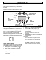
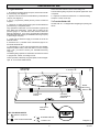
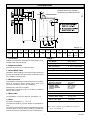
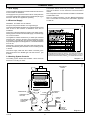
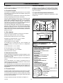
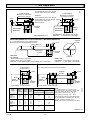
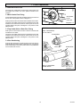
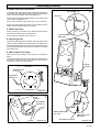
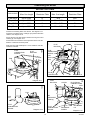
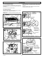
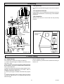
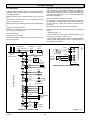
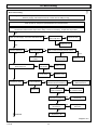
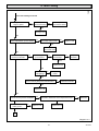
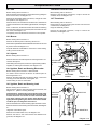
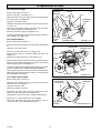
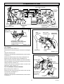
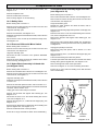
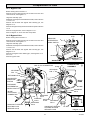
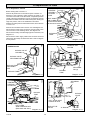
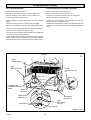
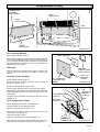
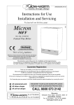
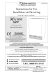
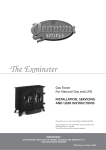
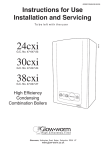
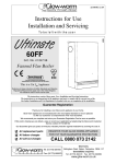
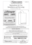
10 Commissioning
Commissioning must only be carried out by a competent person
in accordance with the current issue of BS6798.
Please ensure the “Benchmark” logbook is completed and left
with the user.
Check that the maximum burner pressure is 14.3 mbar +/-0.2
mbar. Adjust the pressure if required by removing the screw
cap and turning the maximum rate adjustment screw on the gas
control valve, see diagram 10.1.
10.1 System Commissioning
10.4 Ignition Rate
Check that the boiler is isolated from the electrical supply, at the
external isolator.
Set the mains electrical switch “B” to 0, located on the controls
fascia, see diagram 2. (Instructions for Use).
Take care not to splash any of the electrical components.
Disconnect the sensing lead at the connection, see diagram
10.2.
Fully open the two water isolating valves, levers in line with the
length of the valves, see diagram 6.1.
Set the mains electrical switch “B” to 1. The electrode will
continue to spark for (10 seconds approx.) to enable the ignition
to be set and checked before going to lockout. Check the
ignition rate is set to 6.0 mbar +/-1.0 mbar, adjust if required by
turning the ignition rate setting potentiometer using the
adjustment tool supplied, If this is not achieved before the boiler
goes to lockout the process can be repeated as required by
pressing the rest button “G”, see diagram 2. (Instructions for
Use). When set, switch the mains electrical switch “B” to 0.
Reconnect the sensing lead.
Make sure that the automatic air vent is operating correctly by
loosening the cap, ensuring hole is directed away from controls.
Flush out the whole system.
Refill the system, refer to Section 4.9 and diagram 4.3, check the
operation of the safety valve, by allowing the water pressure to
rise until the valve operates. The valve should open within +/0.3bar of the 3 bar preset pressure. Where this is not possible
carry out a manual check by turning the safety valve knob in the
direction of the arrow.
Set mains electrical switch “B” to 1, depress the rest button “G”
if required. Check the appliance operates correctly.
Clear any air locks and check the system for water soundness.
Isolate the boiler from the electrical supply.
Release the water pressure to the initial system design pressure.
Replace plastic plugs, screw cap and adjusting tool.
10.2 Initial Lighting, testing and Adjustment
Disconnect the pressure gauge, tighten the burner pressure
test point screw . Test for gas soundness. Take care not to
splash any of the electrical components.
Check the boiler is Isolated from the electrical supply, at the
external isolator.
10.5 System - Commissioning
Turn on the gas service cock, slot in line with the length of the
cock, see diagram 6.1.
Fully open all radiator valves.
Purge the gas supply and test for soundness.
Set the heating system in operation and balance the radiators.
Lower the controls fascia by removing the two securing screws,
see diagram 9.1.
Refer to Section 4.6 and diagram 4.1.
Loosen the burner pressure test point screw , see diagram 10.1,
and connect a suitable pressure gauge.
Allow the system to reach maximum temperature then switch
off, isolate the boiler from the electrical supply and drain the
system rapidly whilst still hot.
Switch on the electrical supply at the external isolator and check
all remote controls, thermostats and programmers are switched
on and are calling for demand.
Remove the inner case front.
Fill and vent the system as described in Section 10.1. Add
inhibitor, if applicable, refer to Section 4.10.
Set the mains electrical switch “B” to 1, located on the controls
fascia, see diagram 2. (Instructions for Use).
Fit the inner case front.
If the red light “F” comes “ON”, the boiler will not work. Depress
the boiler safety cutoff reset button “G”, see diagram 2.
(Instructions for Use).
10.6 Completion
Fit the side panels, hook into the threaded lugs at the top, see
diagram 10.4.
The pump will circulate water through the appliance and the
burner will light.
Refit controls fascia fastening through holes in the side panels,
secure with four screws in the base
10.3 Burner Pressure
Fit the case base, slide back to engage the rear lugs, secure
with two screws, see diagram 10.3.
The burner pressure is factory preset and no adjustment should
be required.
Fit the outer case front by locating it on one side then wrap it
around locating it on the opposite side, slide down locating on
to the threaded lugs at the top and behind the controls cover at
the bottom, secure all the panels with nuts , see diagram 10.5.
The burner pressure should be checked with the system cold to
prevent any modulation of the gas pressure and the inner case
front fitted.
Remove the three plastic plugs on the rear of the controls fascia,
using the adjustment tool supplied turn the maximum burner
pressure potentiometer on the control board (P.C.B.) to minimum
(fully anticlockwise). Check the minimum burner pressure is
2.3 mbar +/-0.2 mbar. Adjust the pressure if required by adjusting
the minimum burner pressure potentiometer, see diagram 10.2.
Set the boiler and any remote control to the desired settings,
then close the control cover door.
Turn the maximum burner pressure potentiometer to maximum,
(fully clockwise).
221872B
22