1
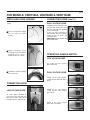
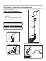
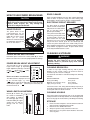
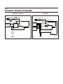
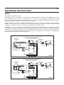
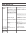
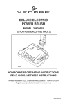
CENTRAL VACUUM POWER UNIT
! FOR HOUSEHOLD USE ONLY !
AB0001
For Power Unit
Broan models VX3000C, VX6000C, VX12000C
HOMEOWNER'S OPERATING INSTRUCTIONS
Broan-NuTone Canada Inc.; Mississauga, Ontario www.broan.ca 877-896-1119
REGISTER YOUR PRODUCT ONLINE AT: www.broan.ca
30042323 rev. I
page 2
IMPORTANT SAFETY
INSTRUCTIONS
•
Do not unplug the unit by pulling on cord. To unplug, grasp
the plug, not the cord.
•
Do not handle plug or appliance with wet hands.
•
Keep your work area well lighted.
SAVE THESE INSTRUCTIONS
•
READ ALL INSTRUCTIONS BEFORE USING
THIS APPLIANCE
Connect to a properly grounded outlet only. See grounding
instructions shown on page 9.
•
Store your cleaner indoors in a clean, dry area.
•
Any servicing other than that recommended in this manual
should be performed by an authorized service facility.
•
We recommend that your unit be inspected by a
specialized technician once a year.
When using an electrical appliance, basic precautions should
always be followed, including the following:
!
WARNING
To reduce the risk of fire, electric shock, or injury:
•
Do not use on wet surfaces or outdoors.
•
Do not allow to be used as a toy. Close attention is necessary
when used by or near children.
•
Use only as described in this manual. Use only manufacturer's
recommended attachments.
CAUTION
For all models, DO NOT REMOVE either of the TOP
red cap plugs that are glued to the unit. Removing
these glued plugs will damage the unit. Only
remove and use the outlets covered by the green
BOTTOM plugs.
•
Do not put any object into openings. Do not use with any
opening blocked; keep free of dust, lint, hair and anything
that may reduce air flow.
•
Keep hair, loose clothing, fingers and all parts of body
away from openings and moving parts.
•
Do not pick up anything that is burning or smoking, such as
cigarettes, matches, or hot ashes.
•
Do not use without filter in place.
•
Do not use to blow leaves or debris.
•
Do not vacuum liquids or fine powders (such as drywall dust).
•
Do not put any object on the unit.
•
Ensure air flows freely to both side intake vents and
exhausts unobstructed from top outlet.
•
Do not install the unit horizontally.
•
Do not use the pail as a wash bucket.
•
Do not use the pail as a stool.
•
Turn off all controls before unplugging.
•
Use extra care when cleaning on stairs.
•
Avoid picking up sharp objects.
•
Do not use to pick up flammable or combustible liquids
such as gasoline or use in areas where they may be present.
•
Do not use with damaged cord or plug. If appliance is not
working as it should, if it has been dropped, damaged, left
outdoors, or dropped into water, return it to a Service Center.
OPERATION
The power unit is located away from the everyday living areas
of your home – usually in the garage, basement, or utility
room. Through a network of strong, lightweight tubing, the
power unit connects to inlets strategically placed throughout
your home. To clean, attach cleaning tools to the system's
hose and insert the hose into an inlet. The system is turned on
by a power switch on the hose. As you vacuum, dirt and dust
is transported to the power unit where it remains in a debris
pail until emptied.
!
WARNING
To avoid electric shock, never use hose and tools
on a wet surface. To avoid fire hazard, do not use
vacuum to pick up matches, fireplace ashes, or
smoking material.
•
This device has been evaluated by the appropriate listing
agencies and is intended for household use only.
The system status indicator light(s) on the front of the power
unit indicate that the power unit is ready for use. Under normal
operation, the light(s) will be green. (A red light on Broan
models VX6000C or VX12000C indicates a need to empty
pail. See page 4 for instructions.)
When you are ready to clean, attach the wand and cleaning
tool onto the end of the hose. Open the inlet cover and insert
the end of the hose into the inlet.
For non-switched hoses, inserting the hose automatically
turns on the power unit; removing the hose shuts off the power
unit. Some hoses have switches which can be used to activate
power unit.
NOTE: The inlet located on the power unit does not
automatically work when the hose is inserted. To
turn on the power unit inlet, use the rocker switch
located on the side of the power unit.
Use the cleaning tools as you would for any other vacuum
cleaner. Avoid picking up pine needles, coffee sticks, and other
similar objects. These kinds of objects may become lodged in
the hose or tubing.
page 3
FOR MODELS: VXKIT300A, VXKIT600E & VXKIT1200E
INSTALLING HOSE HANGER
CONNECTING HOSE (CONT’D)
If not already done, install the hose hanger by following these
3 steps.
DUAL VOLTAGE HOSE
In addition to connecting into wall
inlet (A), dual voltage hose must
also be connected to a standard
electrical outlet (B).
If your new hose connection is
not compatible with the telescopic
handle of your unit, please call
1-888-882-7626.
IMPORTANT: Do not return the
hose to the store.
1 Place one loop of the hanger
over the other (as shown
beside).
A
B
AO0023
AR0031
2 Using a screwdriver, secure
the hanger to the wall with the
provided screw. Insert a
plastic anchor if necessary.
OPERATING HANDLE SWITCH
LOW VOLTAGE HOSE
The switch will turn vacuum
power unit on/off.
AR0029
AD0025
3 Wind hose around it’s hanger
DUAL VOLTAGE HOSE
when not in use.
Switch on the right position:
central vacuum mode with power
brush.
AR0030
CONNECTING HOSE
AD0033
A
LOW VOLTAGE HOSE
Switch on the left position:
central vacuum mode without
power brush.
To ensure proper operation of
hose, insert hose into wall inlet
(as shown beside). Align tab up
with depression in wall inlet (A).
AD0032
Switch in the center: vacuum
power unit is turned off.
AO0022
AD0026
page 4
FOR MODELS: VXKIT600E AND VXKIT1200E
HOW TO ASSEMBLE
POWER BRUSH/WAND/HANDLE
1.
2.
3.
4.
Read important safety instructions before installing power
brush.
Ensure hose is disconnected from power supply before
installing power brush.
Push wand into power brush neck so that the lock button
snaps in place.
Connect hose handle into wand quick connector and
ensure that the prongs are aligned with the receptacle
holes. Push until lock button snaps in place.
LOCK
BUTTON
HOSE
HANDLE
RECEPTACLE
PRONGS
QUICK
CONNECTOR
WAND
CAUTION
Always check underside of product for any
obstructions prior to use.
!
WARNING
WAND
GRIP
Never leave electric power brush unattended while
it is plugged in.
HOSE HANDLE TO WAND CONNECTION
HOSE
HANDLE
LOCK
BUTTON
RECEPTACLE
LOCK
BUTTON
PRONGS
POWER
BRUSH
HOSE HANDLE
RELEASE BUTTON
WAND
AO0021
AO0019
WAND TO POWER BRUSH CONNECTION
WAND PART NO. 08949
LOCK BUTTON
POWER BRUSH
NECK
HEIGHT
ADJUSTMENT
PEDAL
AO0020
WAND AND HOSE COMPATIBILITY
VACUUM HOSE PART NOS.
32DVB, 32DVN & BN32DV
WAND
RELEASE
PEDAL
HOSE HANDLE
POWER BRUSH
NECK RELEASE
PEDAL
page 5
HOW TO USE POWER BRUSH/WAND
CAUTION
Always pick up hard or sharp objects by hand
before using your power brush. Items such as pins,
hairpins, tacks, crayons, etc., may damage the
brush roll or may break the belt.
WAND RELEASE
The power brush is not
recommended for use on
bare floors. Wand release
pedal (A) on power brush
allows you to quickly
disconnect wand and switch
to combination floor/rug tool
for use on bare floors.
C
A
B
AO0020
CAUTION
EDGE CLEANER
Brush extends full width for effective edge cleaning along both
sides of nozzle. To operate, simply run cleaner along edge
board. Rubber bumper protects furniture and baseboards.
ELECTRONIC CIRCUIT BREAKER
The power brush is equipped
with an electronic circuit breaker
that protects the motor and the
belt if a too large object is
picked up accidentally.
If the power brush stops while
vacuuming, turn the power unit
AD0030
off using handle. Release the
H
power brush from the wand
and turn it over to see if there is an obstruction. When brush
roll jam has been cleared, press the reset button (H) and
connect the power brush back to the wand. Finally, turn the
power unit/power brush back on. If it fails to restart or continues
to trip without any apparent reason, the power brush must be
serviced by an authorized service center.
Always unlock brush neck before use.
CLEANING & STORAGE
POWER BRUSH NECK RELEASE
Push down power brush neck release pedal (B) to unlock
brush neck. Return the neck to the upright position for storage.
POWER BRUSH HEIGHT ADJUSTMENT
The icons (D) refer to the carpet pile
height. Select height by depressing
height adjustment pedal (C) to desired
position:
(Extra-Low),
(Low),
(Medium) or
(High).
HEIGHT ADJUSTMENT
Disconnect electrical supply before servicing or
cleaning the unit. Failure to do so can result in
electrical shock or personal injury from cleaner
suddenly starting.
CLEANING BRUSH ROLL
FLOOR HEIGHT
D
In order to keep high cleaning efficiency and to prevent
damage to your vacuum cleaner, the brush roll must be
cleaned every time the belt is changed.
The brush roll must also be cleaned according to the following
schedule:
LED INDICATORS
The LEDs show the carpet pile covered
AD0022
by the selected height, e.g.: when
(High) is selected, all LEDs will be lit, since this height
covers all pile heights. So if
(Extra-Low) is selected, only the
lowest LED will be lit.
WAND LENGTH ADJUSTMENT
Extend (E) or shorten (F)
the wand to comfortable
work position by holding
the wand grip (G) in one
hand and sliding the upper
section (the one with the
prongs) with the other
hand.
! WARNING
VACUUM CLEANER USE
Heavy (used daily)
Moderate (2-3 times per week)
Light (1 time per week)
CLEAN BRUSH ROLL
Every week
Every month
Every 2 months
Check and remove hair, string and lint build-up frequently in
the brush roll and end cap areas. Remove any dirt or debris in
the belt path and in the brush roll areas.
CLEANING HOUSING
E
To keep the power brush housing clean, it can be wiped with
a damp cloth and a mild soap solution, then thoroughly dried.
Never use any type of chemical as they can damage the housing.
STORAGE
F
1.
G
AD0024
AD0023
2.
3.
4.
Ensure that hose and power cord are disconnected from
wall inlet before unplugging power brush.
Disconnect hose handle from wand.
Always keep hose neatly coiled when not in use.
When not in use, the power brush should be stored in a
clean, dry place.
page 6
HOW TO CHANGE BRUSH ROLL
MAINTAINING THE POWER BRUSH
! WARNING
Disconnect electrical supply before servicing or
cleaning the unit. Failure to do so can result in
electrical shock or personal injury from cleaner
suddenly starting.
HOW TO CHANGE BELT
! WARNING
Motor shaft can become hot during normal use. To
prevent burns, avoid touching the motor shaft
when replacing the drive belt.
FIG. 1
1.
Replace brush roll when brush roll brissles are worn to the
base support bars level.
1.
Turn power brush over and using a Phillips no. 2 screwdriver,
remove the 3 brush roll cover retaining screws (Fig. 1)
and set aside.
2.
Remove brush roll cover. (Fig. 2)
3.
To free brush roll from base, start by sliding the belt side
end and pull brush roll sideways (1). Once disengaged
from housing, lift brush roll (2) out of its compartment
(Fig. 3).
4.
Disengage brush roll from belt. Discard worn brush roll.
5.
Insert new brush roll through belt until belt is seated in its
place. Push down brush roll back in place.
6.
Finalise the installation by reversing steps 2 to 1.
RETAINING
SCREWS
Turn power brush over and
using a Phillips no. 2 screwdriver,
remove the 3 brush roll cover
retaining screws (Fig. 1) and
set aside.
AB0010
FIG. 2
2.
SERVICE INFORMATION
Remove brush roll cover.
(Fig. 2)
To avoid unnecessary service calls, check the belt and brush
roll often. Replace the belt if it is stretched or cracked. Clean
the brush roll bristles when they are wrapped with thread and
hairs. Build-up could cause the brush to rotate unevenly.
BELT
BRUSH
ROLL
The model number and serial number are indicated on the rating
label located underneath the power brush. Always refer to
these numbers when inquiring about service.
AB0011
3.
4.
To free brush roll from
base, start by sliding the
belt side end and pull
brush roll sideways (1).
Once disengaged from
housing, lift brush roll (2)
out of its compartment
(Fig. 3).
FIG. 3
2
2
1
POWER BRUSH SERVICE PARTS
AB0012
Disengage brush roll from
worn belt and extract the belt
from motor shaft by a
twisting motion in the enlarge
area (I) specifically made for
that purpose (Fig. 4).
NOTE: The motor is permanently lubricated and sealed. Do
not oil the motor at any time.
3
FIG. 4
1
4
2
I
5
AB0013
5. Install new belt by reversing steps 4 to 1.
NOTE: To ease belt replacement, start by inserting one end
around the motor shaft in the enlarged area (I). Insert
brush roll through belt until belt is seated in its place.
Push down brush roll back in place.
AA0002
KEY NO.
PART NO.
DESCRIPTION
1
2
3
4
5
09234
09233
09236
09235
18651
Belt
Brush roll
Brush roll cover with screws
Wand release pedal
Wand
Order Service Parts by “Part No.”, not by “Key No.”
page 7
FOR ALL MODELS
VACUUM POWER CONTROL
EMPTYING THE DEBRIS PAIL
The wand ends of the deluxe hoses are equipped with a control
ring to regulate suction. The control ring covers a “bleeder”
hole. Open the hole to reduce the suction for cleaning
draperies, small rugs, and other light fabrics. Some very thick,
plush carpets with high density yarns also require reduced
suction to make the nozzle easier to push. Be sure to close the
control ring completely over the hole to produce the maximum
power required for most other cleaning tasks.
Your power unit has a permanent filter that is self cleaning
under normal conditions. The filter protects the motor and
stops small dirt particles from escaping to the outside of the
power unit. The filter cleans itself by moving up when the
power unit starts, and dropping down when the unit is turned
off. The filter can be removed by means of a pull-tab for
cleaning if desired. Be sure to reinstall properly. Correct
placement is critical to insure proper protection for the motor.
WHEN TO EMPTY THE DEBRIS PAIL
1. Release both carry handles on side of the unit by pulling
out and then pushing up. (FIGURE 14). Holding the pail by
the handles, lower it from unit (FIGURE 15).
Broan model VX3000C has a single indicator light that
remains green. The level of pail fill for this model can be
determined by either viewing through the window on the pail or
releasing the carry handles and checking the level of debris in
the pail.
Broan models VX6000C & VX12000C have the LED indicators
that show the status of the level of debris in the pail. The first
three lights remain green as pail fills. The fourth light is amber
and will come on to alert you that the pail is nearly full. When
the fifth light turns red it is time to empty the pail (see
CONTROL PANEL DIAGRAM A below).
2. Carry pail to trash receptacle and empty.
3. Reattach pail using handles.
4. Push Reset button on control panel. Light on control panel
will change to green on Broan models VX6000C
& VX12000C.
FIGURE 14
FIGURE 15
CONTROL PANEL DIAGRAM A
Broan VX3000C
AR0001
Manually check
pail to determine
fill level.
GREEN ONLY
VX12000C
Timed pail
full indicators
GREEN AMBER RED RESET
Utility valve (Circled in FIGURE 15), next to power unit, can be
used to service area around where power unit is installed.
CLEANING THE INTERNAL FILTER
Broan VX6000C &
AC0001
AR0002
When emptying the debris
pail, it is a good idea to also
clear any dust and dirt that
may have accumulated on
the internal filter media. To
do this, simply open the
direct door, reach in and tap
the top of the internal filter
(FIGURE 16). This will
release any loose debris into
the pail. You may empty the
pail again at this point but it
is not necessary as any
amounts of dirt and dust will
be minimal. Close the door.
FIGURE 16
AR0003
page 8
INTERNAL WIRING DIAGRAMS
• VX3000C • VX6000C
• VX12000C
WHITE
BLACK
RED OR WHITE
BLACK
GREEN
GREEN
240 VOLTS GREEN
120 VOLTS
THERMAL
PROTECTOR
BLACK
AE0005A
MOTOR
CONTROL
CONTROL
BOARD
BLACK
THERMAL BLUE
PROTECTOR
RED OR WHITE
BLACK
MOTOR
RED OR WHITE
YELLOW
YELLOW
WHITE
BLUE
AE0027A
YELLOW
CONTROL
BOARD
YELLOW
BLUE
BLUE
THERMAL
PROTECTOR
GREEN
BLUE
BLUE
GREEN
GREEN
CONTROL
BLACK
MOTOR
page 9
GROUNDING INSTRUCTIONS
WIRING
This section refers to Figure 17 and 18.
Grounding Instructions – This appliance must be grounded. If it should malfunction or break down, grounding provides a path of
least resistance for electric current, to reduce the risk of electric shock. This appliance is equipped with a cord
having an equipment-grounding conductor and grounding plug. The plug must be plugged into an appropriate outlet that is properly
installed and grounded in accordance with all local codes and ordinances.
Danger – Improper connection of the equipment-grounding conductor can result in a risk of electric shock. Check with a qualified
electrician or service person if you are in doubt as to whether the outlet is properly grounded. Do not modify the plug provided with
the appliance – if it will not fit the outlet, have a proper outlet installed by a qualified electrician.
This appliance is for use on a standard 120 VAC, dedicated 15-amp branch circuit with a NEMA 5-15R receptacle or a dedicated
20-amp branch circuit with a NEMA 5-20R receptacle for Broan models VX3000C & VX6000C. For Broan model VX12000C, a dedicated
nominal 240 VAC, individual 20-amp branch circuit with NEMA 6-20R receptacle is required. Make sure that the appliance is
connected to an outlet and has a grounding attachment plug that looks like the plug shown in either Figure 17 or 18 depending on
the model. No adapter should be used with this appliance.
Broan VX3000C & VX6000C
NOTE: INLET LEADS TO BE CONNECTED TO POWER UNIT
TERMINALS USING CRIMP CONNECTORS
AND LOW VOLTAGE WIRE HARNESS
LOW VOLTAGE
WIRE HARNESS
NORTH AMERICA
AC ELECTRIC
OUTLET
120 VOLT GROUNDED
OUTLET BOX
LOW VOLTAGE WIRE
CRIMP CONNECTORS
GROUND PIN
NEMA 5-15R
OR
NEMA 5-20R
INLET
LEADS
POWER
CORD
POWER
UNIT
TO
OTHER
INLETS
MODEL V133 18/2 WIRE
FIGURE 17
AE0029A
Broan VX12000C
NOTE: INLET LEADS TO BE CONNECTED TO POWER UNIT
TERMINALS USING CRIMP CONNECTORS
AND LOW VOLTAGE WIRE HARNESS
LOW VOLTAGE
WIRE HARNESS
NORTH AMERICA
AC ELECTRIC
OUTLET
LOW VOLTAGE WIRE
240 VOLT GROUNDED
OUTLET BOX
CRIMP CONNECTORS
GROUND PIN
NEMA 6-20R
INLET
LEADS
POWER
CORD
POWER
UNIT
TO
OTHER
INLETS
AE0010A
MODEL V133 18/2 WIRE
FIGURE 18
page 10
TROUBLESHOOTING GUIDE
Read before calling Service Center.
PROBLEMS
POSSIBLE
CAUSES
POSSIBLE REMEDY
1.Loss or decrease of • Debris pail is completely full.
• Empty debris pail as described on page 7.
vacuum occurs.
• Obstruction in the hose. A blockage in the hose • Insert handle end of hose into utility valve at
can be determined by inserting the hose into any power unit. Turn unit on. This will reverse normal
wall inlet and, while power unit is running, check air flow through the hose and dislodge any clogs.
each additional inlet for normal suction by holding
the palm of your hand over the open inlet. If normal
suction is felt at all other inlets, insert the hose
into a second inlet. If the blockage still exists it is
located in the hose. However, if the blockage
does not occur when the hose is changed, the
blockage is probably located in the tubing system
leading to the original inlet.
• Obstruction in the tubing system inside the walls. • Insert hose end into any inlet with power unit running,
place the palm of your hand over the opposite
end of the hose. When you can feel the suction
increase, hold your hand over the hose end for a
few seconds and then quickly remove your hand.
This procedure repeated several times should
clear the obstruction. If the blockage is not
cleared, contact your nearest Service Center.
• Check all wall inlet covers to be sure they are
• Wall inlet cover not properly sealed.
closed and sealed tightly.
• Exhaust tubing or vent clogged.
• Inspect and remove any blockages.
2.Power unit does not • Defective inlet. Check other wall inlets.
• Replace defective wall inlet.
start, or shuts off during • Thermoprotector has been activated OR there is • Turn unit off for 20 minutes then plug unit back in.
normal operation with a tripped circuit breaker on the unit.
If unit does not start, look for the tripped circuit
no LED showing red or
breaker behind the unit, a white button has
illuminated.
popped up, push it back to reset it. If circuit
breaker trips again, unplug your unit and contact
your local Service Center.
• Blown fuse or tripped circuit breaker on house • Replace fuse or reset circuit breaker on house
electrical panel.
electrical panel.
• Replace hose as required.
• Defective hose.
• 1) Push Reset button while unit is engaged OR
• Microprocessor lockup.
NOTE:This applies only to Broan VX6000C 2) Unplug unit completely for 60 seconds.
& VX12000C.
• Contact your local Service Center.
• Low line voltage.
3.Power unit fails to stop • An electrical short has occurred somewhere in • A complete check of all wall inlets and power unit
when the hose is the system.
low voltage control lead connections.
removed.
Contact your authorized Service Center.
4.Power unit shuts off • Debris pail full sensing has been activated.
during normal operation,
lights on unit, wall valve
and hose are all red.
• Empty debris pail as described in page 7.
5.On Broan VX6000C & • Low line voltage.
VX12000C units only,
all lights on control
panel flash when unit is
first plugged in.
• Contact your local Service Center.
page 11
SERVICE PARTS LIST
(BROAN MODELS VX3000C, VX6000C & VX12000C)
9
8
4
2
5
6
7
3
AL0001
KEY
PART NO.
NO.
10941189
1
10941191
2 10941192
3 10941199
10941232
4 10941233
10941195
10941235
5 10941236
10941231
30100528
6
30100527
30010272
7
30010270
10941217
8
10941218
10941211
9
10941213
1
DESCRIPTION
Pail assembly VS
Pail assembly TS
Door assembly
Latch kit (with screws)
VS PCB’s assembly (including mother, daughter and screws)*
TS1 PCB’s assembly (including mother, daughter and screws)*
TS2 Motherboard/Daughterboard S/A incl. screws*
VS motor with motor harness, fuse with fuse harness, circuit breaker*
TS1 motor with motor harness, fuse with fuse harness, circuit breaker*
TS2 motor with motor harness, fuse harness, circuit breaker*
Pail gasket TS
Pail gasket VS
Cyclonic filter VS
Cyclonic filter TS
Motor Chamber VS with foam and logo*
Motor Chamber TS with foam and logo*
Top cap VS with logo
Top cap TS with logo
NOTE: Order service parts by “Part No.” - not by “Key No.”
*This part MUST be removed and installed by a qualified technician.
VX3000C VX6000C VX12000C
X
X
X
X
X
X
X
X
X
X
X
X
X
X
X
X
X
X
X
X
X
X
X
X
X
X
X
page 12
WARRANTY
BROAN MODELS VX3000C, VX6000C, VX12000C
BROAN-NUTONE CANADA INC.
CENTRAL VACUUM POWER UNIT
LIMITED LIFETIME WARRANTY
Broan-NuTone Canada warrants to the original consumer purchaser that its central vacuum power unit will be free from defects in materials and
workmanship for as long as you own your home in which it was originally installed with the exception of the motor and electronic components
which will be warranted for five (5) years. The first year of this warranty covers the parts and labor in an authorized service center. THERE ARE
NO OTHER WARRANTIES, EXPRESSED OR IMPLIED, INCLUDING, BUT NOT LIMITED TO, IMPLIED WARRANTIES OF MERCHANTABILITY
OR FITNESS FOR A PARTICULAR PURPOSE.
During these time periods, Broan-NuTone Canada will, at its option, repair or replace the power unit or part without charge, which is found to
be defective under normal use and service. THIS WARRANTY DOES NOT APPLY TO THE INSTALLATION OR THE PARTS USED IN THE
INSTALLED TUBING SYSTEM. All central vacuum hoses, electric or air-driven brushes, filters, attachments and accessories are warranted for
one (1) year from the original purchase date with the exception to consumables such as light bulbs and belts.
This warranty does not cover (a) normal maintenance and service or (b) any products or parts which have been subject to misuse, negligence,
accident, improper maintenance or repair (other than by Broan-NuTone Canada or an authorized representative), faulty installation or installation
contrary to recommended installation instructions.
The duration of any implied warranty is limited to the period as specified for the express warranty.
BROAN-NUTONE CANADA’S OBLIGATION TO REPAIR OR REPLACE, AT BROAN-NUTONE CANADA’S OPTION, SHALL BE THE
PURCHASER'S SOLE AND EXCLUSIVE REMEDY UNDER THIS WARRANTY. BROAN-NUTONE CANADA SHALL NOT BE LIABLE FOR
INCIDENTAL, CONSEQUENTIAL OR SPECIAL DAMAGES ARISING OUT OF OR IN CONNECTION WITH PRODUCT USE OR PERFORMANCE.
Please do not return your unit to place of purchase. Please visit www.broan.ca for your closest service center. You may also call 1-888-882-7626
for the name of an authorized representative in your area. This warranty supersedes all prior warranties.
To qualify for warranty service, you must notify Broan-NuTone Canada at the address or telephone number stated below. We will then forward
you the authorized service depot in your area. You will be required to present evidence of the original purchase date.
Date of Installation
Builder or Installer
Model Number and Product Description
IF YOU NEED ASSISTANCE OR SERVICE
For the location of your nearest Broan-NuTone Canada Inc. dealer, dial toll free: 1-888-882-7626
Please be prepared to provide: Product model number ● Date and proof of purchase ● The nature of the difficulty
Broan-NuTone Canada Inc. 1140 Tristar Drive, Mississauga, Ontario L5T 1H9
Product specifications subject to change without notice.
Printed in Canada.