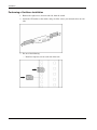
1
HP 1x4 USB/PS2 KVM Switch
User Guide
July 2004 (First Edition)
Part Number 372284-001
© Copyright 2004 Hewlett-Packard Development Company, L.P.
The information contained herein is subject to change without notice. The only warranties for HP products and
services are set forth in the express warranty statements accompanying such products and services. Nothing herein
should be construed as constituting an additional warranty. HP shall not be liable for technical or editorial errors
or omissions contained herein.
Microsoft and Windows are U.S. registered trademarks of Microsoft Corporation. Linux is a U.S. registered
trademark of Linus Torvalds.
HP 1x4 USB/PS2 KVM Switch User Guide
July 2004 (First Edition)
Part Number 372284-001
Contents
About This Guide
Intended Audience...................................................................................................................................... vii
Important Safety Information ..................................................................................................................... vii
Symbols on Equipment .............................................................................................................................. vii
Rack Stability ............................................................................................................................................ viii
Symbols in Text......................................................................................................................................... viii
Text Conventions ...................................................................................................................................... viii
Getting Help .................................................................................................................................................ix
HP Technical Support ............................................................................................................................ix
HP Website ............................................................................................................................................ix
HP Authorized Reseller .........................................................................................................................ix
Reader’s Comments .....................................................................................................................................ix
Chapter 1
Introduction
Overview ................................................................................................................................................... 1-1
Features ..................................................................................................................................................... 1-1
Hardware Requirements ............................................................................................................................ 1-2
Front Panel ................................................................................................................................................ 1-3
Rear Panel.................................................................................................................................................. 1-4
Chapter 2
Installation
Desktop Model Hardware Installation....................................................................................................... 2-1
Rackmount Model Hardware Installation ................................................................................................. 2-4
Performing a Side-Mount Installation ................................................................................................ 2-5
Performing a Cantilever Installation ................................................................................................... 2-6
Cabling the Switch.............................................................................................................................. 2-7
Chapter 3
Operation
Hot Plugging.............................................................................................................................................. 3-1
Powering Off and Restarting ..................................................................................................................... 3-1
Port Numbering ......................................................................................................................................... 3-1
Hotkey Operation ...................................................................................................................................... 3-1
Port Switching..................................................................................................................................... 3-2
Auto Scanning..................................................................................................................................... 3-3
HP 1x4 USB/PS2 KVM Switch User Guide
iii
Contents
Hotkey Setting Mode .................................................................................................................................3-3
Invoking HSM.....................................................................................................................................3-3
Alternate HSM Invocation Keys .........................................................................................................3-4
Alternate Port Switching Keys ............................................................................................................3-4
Keyboard Operating Platform .............................................................................................................3-4
Listing Hotkey Settings .......................................................................................................................3-5
USB Reset ...........................................................................................................................................3-5
Hotkey Beeper Control........................................................................................................................3-5
Disabling Port Switching Keys ...........................................................................................................3-5
Restoring Default Settings...................................................................................................................3-5
HSM Summary Table..........................................................................................................................3-6
Keyboard Emulation ..................................................................................................................................3-6
Sun Keyboard ......................................................................................................................................3-6
Macintosh Keyboard ...........................................................................................................................3-7
Chapter 4
Firmware Upgrade Utility
Before You Begin ......................................................................................................................................4-1
Starting the Upgrade ..................................................................................................................................4-3
Chapter 5
Troubleshooting
Appendix A
Regulatory Compliance Notices
Regulatory Model Number ....................................................................................................................... A-1
Federal Communications Commission Notice ......................................................................................... A-1
Class A Equipment............................................................................................................................. A-1
Class B Equipment ............................................................................................................................. A-2
Declaration of Conformity for Products Marked with the FCC Logo, United States Only ............... A-2
Modifications...................................................................................................................................... A-2
Cables ................................................................................................................................................. A-3
Canadian Notice (Avis Canadien)............................................................................................................. A-3
Class A Equipment............................................................................................................................. A-3
Class B Equipment ............................................................................................................................. A-3
European Union Regulatory Notice.......................................................................................................... A-3
Japanese Notice......................................................................................................................................... A-5
Power Cord Statement for Japan ........................................................................................................ A-5
Korean Notice ........................................................................................................................................... A-5
Class A Equipment............................................................................................................................. A-5
Class B Equipment ............................................................................................................................. A-6
BSMI Notice ............................................................................................................................................. A-6
Appendix B
Electrostatic Discharge
Preventing Electrostatic Damage .............................................................................................................. B-1
Grounding Methods .................................................................................................................................. B-2
iv
HP 1x4 USB/PS2 KVM Switch User Guide
Contents
Appendix C
Specifications
Index
HP 1x4 USB/PS2 KVM Switch User Guide
v
About This Guide
This guide provides information for installation and operation of the switch.
Intended Audience
This guide is intended for individuals requiring information about the use of switches.
Important Safety Information
Before installing this product, read the Important Safety Information document provided.
Symbols on Equipment
The following symbols may be placed on equipment to indicate the presence of potentially
hazardous conditions.
WARNING: This symbol, in conjunction with any of the following symbols, indicates
the presence of a potential hazard. The potential for injury exists if warnings are not
observed. Consult your documentation for specific details.
This symbol indicates the presence of hazardous energy circuits or electric shock
hazards. Refer all servicing to qualified personnel.
WARNING: To prevent injury from electric shock hazards, do not open this enclosure.
Refer all maintenance, upgrades, and servicing to qualified personnel.
This symbol indicates that the component exceeds the recommended weight for
one individual to handle safely.
Weight in kg
Weight in lb
WARNING: To prevent personal injury or damage to the equipment, observe
local occupational health and safety requirements and guidelines for manual
material handling.
HP 1x4 USB/PS2 KVM Switch User Guide
vii
About This Guide
Rack Stability
WARNING: To prevent personal injury or damage to the equipment, verify that:
•
The leveling feet are extended to the floor.
•
The full weight of the rack rests on the leveling feet.
•
The stabilizing feet are attached to the rack if it is a single-rack installation.
•
The racks are coupled together if it is a multiple-rack installation.
•
Only one component is extended at a time. A rack may become unstable if more
than one component is extended for any reason.
Symbols in Text
These symbols can be found in the text of this guide. They have the following meanings.
WARNING: Text set off in this manner indicates that failure to follow directions in the
warning could result in bodily harm or loss of life.
CAUTION: Text set off in this manner indicates that failure to follow directions could result in
damage to equipment or loss of information.
IMPORTANT: Text set off in this manner presents clarifying information or specific instructions.
NOTE: Text set off in this manner presents commentary, sidelights, or interesting points of information.
Text Conventions
This document uses the following conventions:
viii
•
Italic type is used for complete titles of published guides or variables. Variables include
information that varies in system output, in command lines, and in command parameters
in text.
•
Bold type is used for emphasis, for onscreen interface components (window titles, menu
names and selections, button and icon names, and so on), and for keyboard keys.
•
Monospace typeface is used for command lines, code examples, screen displays,
error messages, and user input.
•
Sans serif typeface is used for uniform resource locators (URLs).
HP 1x4 USB/PS2 KVM Switch User Guide
About This Guide
Getting Help
If you have a problem and have exhausted the information in this guide, further information
and other help is available in the following locations.
HP Technical Support
For telephone numbers of worldwide Technical Support Centers, go to http://www.hp.com.
Have the following information available before you call:
•
Technical support registration number (if applicable)
•
Product serial number
•
Product model name and number
•
Applicable error messages
•
Add-on boards or hardware
•
Third-party hardware or software
•
Operating system type and revision level
•
Power management software type and version
HP Website
For information on this product as well as the latest drivers, firmware, and service packs, go
to http://h18004.www1.hp.com/products/servers/proliantstorage/rackoptions/list.html#console.
HP Authorized Reseller
For the name of your nearest HP authorized reseller:
•
In the United States, call 1-800-345-1518.
•
In Canada, call 1-800-263-5868.
•
Elsewhere, refer to the HP website for locations and telephone numbers.
Reader’s Comments
To comment on this guide, send an email to [email protected].
HP 1x4 USB/PS2 KVM Switch User Guide
ix
1
Introduction
Overview
The HP 1x4 USB/PS2 KVM Switch is a four-port keyboard, video, and mouse (KVM) switch
combined with a two-port USB hub. As a KVM switch, four computers can be accessed from
a single keyboard, mouse, and monitor console. Keyboard and mouse data can be transferred
to the computers using a USB connection, or with the traditional PS/2 connection. If a USB
connection is used, the two-port USB hub is available to each of the computers, allowing
each computer to access any peripherals connected to the hub on a one-computer-at-a-time
basis.
Features
•
Dual-function KVM/USB switch
•
Ability to control four computers and two additional USB devices with one console
NOTE: Both USB peripheral ports on the switch rear panel will not function unless USB KVM
cables are used. Cable sets with USB connectors are available for order from the HP website at
http://h18004.www1.hp.com/products/servers/proliantstorage/rack-options/list.html#console.
•
Dual-interface support—PS/2 or USB keyboard and mouse data transport for PC
compatible computers
NOTE: Macintosh and Sun computers must use the USB cable connection. Cable sets with USB
connectors are available for order from the HP website at
http://h18004.www1.hp.com/products/servers/proliantstorage/rack-options/list.html#console.
•
Independent (asynchronous) switching of KVM and peripheral USB ports
•
Fully compliant with the USB 1.1 specification; supports transfer rates of 1.5 to 12 Mb/s
•
Computer selection available using front panel switches or hotkeys
•
LED display for easy status monitoring
•
Auto Scan mode for monitoring all computers
•
Complete keyboard emulation for error-free booting
•
Superior video quality: 2048 x 1536; bi-directional data display channel (DDC2B)
•
Switch refresh rate of 60 Hz
HP 1x4 USB/PS2 KVM Switch User Guide
1-1
Introduction
•
Easy installation; no software required
•
Hot pluggable—Add or remove computers for maintenance without powering down the
switch
•
Microsoft® Windows® 98SE/ME, Windows 2000, Windows XP, Mac OS 8.6 or higher,
Solaris, and Linux host systems supported
Hardware Requirements
The console requires:
•
A VGA, SVGA, or Multisync monitor capable of the highest resolution that will be used
on any computer in the installation
•
A USB style mouse or a PS/2 style mouse with the included PS/2-to-USB interface
adapter
•
A USB style keyboard or a PS/2 style keyboard with the included PS/2-to-USB interface
adapter
Each computer requires:
•
A VGA, SVGA, or Multisync card
•
PS/2 keyboard and mouse ports
Only custom cable sets specifically designed to work with the switch can be used to link to
the computers. Two PS/2 cables with audio connectors (Desktop model) or four PS/2 cables
without audio connectors (Rackmount model) are provided with the switch.
The switch also supports computers that use USB connectors to transfer keyboard and mouse
data. Cable sets with USB connectors are available for order from the HP website at
http://h18004.www1.hp.com/products/servers/proliantstorage/rack-options/list.html#console.
NOTE: The switch USB hub function only works with USB cable set connections. It will not work with
PS/2 cable set connections.
1-2
HP 1x4 USB/PS2 KVM Switch User Guide
Introduction
Front Panel
Figure 1-1: Front panel
Item
1
2
Description
Function
Port
selection
switches
•
Press a switch for longer than 2 seconds to bring the KVM focus, USB
peripherals, and audio focus to the computer attached to the
corresponding port.
•
Press a switch for less than 2 seconds to bring only the KVM focus to
the computer attached to the corresponding port.
•
Press switches 1 and 2 simultaneously for 2 seconds to start Auto
Scan mode. For more information on Auto Scan mode, refer to “Auto
Scanning” in chapter 3 of this guide.
•
Press switches 3 and 4 simultaneously for 2 seconds to perform a
keyboard and mouse reset.
Port LEDs
The Port LEDs are built into the Port Selection Switches. The upper LEDs
are the KVM Port LEDs. The lower LEDs are the USB LEDs.
KVM Port LEDs
•
Dim orange—I ndicates that the computer attached to the
corresponding port is currently online
•
Bright orange—Indicates tha t the computer attached to the
corresponding port is selected for the KVM focus
•
Flashing orange—Indic ates that the computer attached to the
corresponding port is being accessed under Auto Scan mode
USB LEDs
3
USB console
ports
HP 1x4 USB/PS2 KVM Switch User Guide
•
Dim green—In dicates that there is a USB cable connection to the
computer
•
Bright green—I ndicates that the computer attached to the
corresponding port has access to the USB peripherals
Connectors used for attaching a USB keyboard and mouse or the
PS/2-to-USB interface adapter.
1-3
Introduction
Rear Panel
Figure 1-2: Rear panel
Item
1-4
Description
Function
1
Console audio jacks
Connectors used for attaching the cables for the console
microphone and speakers. Each jack is marked with the
appropriate icon.
2
USB hub peripheral ports
Connectors used for attaching USB peripherals, such as
printers and scanners.
3
Firmware upgrade switch
During normal operation, the firmware upgrade switch must be
in the NORMAL position.
4
Firmware upgrade port
The RJ-11 firmware upgrade cable plugs into this connector.
For more information on upgrading the firmware, refer to
chapter 4 of this guide.
5
Power jack
Connector used for attaching the cable for external power.
6
Monitor port
Connector used for attaching the video cable for the console
monitor.
7
CPU ports
Connectors used for attaching the custom cable sets that link
the switch to the computers. Each CPU port includes a
microphone jack, speaker jack, and KVM data connector.
HP 1x4 USB/PS2 KVM Switch User Guide
2
Installation
Desktop Model Hardware Installation
CAUTION: To prevent damage to the equipment:
•
Power down all devices before connecting.
•
Be sure that all devices are properly grounded.
1. Connect the console mouse and keyboard by doing one of the following:
— Connect the USB mouse (1) and keyboard (2) to the USB ports on the switch front
panel.
HP 1x4 USB/PS2 KVM Switch User Guide
2-1
Installation
— Connect the PS/2-to-USB interface adapter to the console USB keyboard port on the
switch front panel. Connect the PS/2 style mouse and keyboard to the appropriate
ports on the adapter.
IMPORTANT: If a USB mouse and USB keyboard are connected to the USB keyboard port on the
switch front panel, do not use the PS/2-to-USB interface adapter to connect a second keyboard
and mouse. Only use the rear panel USB ports to connect USB peripherals.
2. Connect the console speakers (1), microphone (2), and monitor (3) to the appropriate
ports on the switch rear panel.
2-2
HP 1x4 USB/PS2 KVM Switch User Guide
Installation
3. Plug the CPU connector on the KVM cable (3) into any available KVM socket in the
CPU port section on the switch rear panel. Plug the accompanying microphone connector
(2) and speaker connector (1) into the corresponding jacks.
NOTE: The cables that ship with the Rackmount model do not include audio jacks.
4. Plug the PS/2 mouse connector (1), the PS/2 keyboard connector (2), the microphone
connector (3), the speaker connector (4), and the video connector (5) on the KVM cable
into their respective ports on the computer. Be sure that each plug corresponds to its
intended CPU port socket.
NOTE: The cables that ship with the Rackmount model do not include audio jacks.
NOTE: The switch also supports computers that use USB connectors to transfer keyboard and
mouse data. Cable sets with USB connectors are available for order from the HP website at
http://h18004.www1.hp.com/products/servers/proliantstorage/rack-options/list.html#console.
HP 1x4 USB/PS2 KVM Switch User Guide
2-3
Installation
5. Connect external power to the power jack on the switch rear panel using the AC adapter
that came in your kit. Connect the AC power adapter plug to a grounded utility power
source (Desktop models), or connect the appropriate jumper cord between the AC adapter
and an uninterruptible power system (UPS) or a power distribution unit (PDU)
(Rackmount model).
6. Power up the connected computers.
Rackmount Model Hardware Installation
CAUTION: To prevent damage to the equipment:
2-4
•
Power down all devices before connecting.
•
Be sure that all devices are properly grounded.
HP 1x4 USB/PS2 KVM Switch User Guide
Installation
Performing a Side-Mount Installation
1. Remove the eight screws, four on each side, from the switch.
2. Attach the 0U brackets to the switch, using the screws you removed.
3. Install two cage nuts into the side-mount bracket U locations, and secure the switch to the
rails using two M-6 screws, one on each side.
HP 1x4 USB/PS2 KVM Switch User Guide
2-5
Installation
Performing a Cantilever Installation
1. Remove the eight screws, four on each side, from the switch.
2. Attach the 1U brackets to the switch, using six of the screws you removed, three on each
side.
3. Do one of the following:
— Install two clip nuts, one on each side of the rack.
2-6
HP 1x4 USB/PS2 KVM Switch User Guide
Installation
— Install two cage nuts, one on each side of the rack.
4. Secure the switch to the rails, using the appropriate screws.
Cabling the Switch
Connect the switch cables as described in “Desktop Model Hardware Installation.”
HP 1x4 USB/PS2 KVM Switch User Guide
2-7
3
Operation
Hot Plugging
The switch supports USB hot plugging. Components can be removed and added back into the
installation by unplugging their cables from the CPU ports without the need to shut down the
unit.
Powering Off and Restarting
To power off and restart the switch:
1. Disconnect all of the computers from the switch.
2. Disconnect the external power cable from the switch rear panel.
3. Wait 10 seconds, then plug the external power cable back into the switch rear panel.
4. After the switch is powered up, reconnect the computers.
Port Numbering
Each CPU port on the switch is assigned a port number. The port numbers are marked on the
switch rear panel. The Port ID of a computer is the same as the CPU port number to which it
is connected. For example, a computer connected to CPU port 3 has a Port ID of 3.
The Port ID is used to specify which computer gets the KVM focus, USB peripherals, and
audio focus with the hotkey port selection method.
Hotkey Operation
The switch provides an extensive, easy-to-use, hotkey function that makes it convenient to
control and configure the KVM installation from the console keyboard. Hotkeys provide
asynchronous (independent) switching of the KVM focus, USB peripherals, and audio focus.
HP 1x4 USB/PS2 KVM Switch User Guide
3-1
Operation
Port Switching
All port switches begin with pressing the Scroll Lock key twice. Table 3-1 and Table 3-2
describe the actions that each key combination performs.
NOTE: If using the Scroll Lock key conflicts with other programs running on the computer, the Ctrl
key can be used instead. To use the Ctrl key, refer to “Alternate Port Switching Keys” in this chapter.
Table 3-1: Cycling Through Ports
Hotkey
Scroll Lock
Action
Enter
Switches KVM focus, audio focus, and USB peripherals from the port
that currently has the KVM focus to the next port on the installation.
The KVM focus, audio focus, and USB peripherals all go to this port
even if they were initially on different ports.
K Enter
Switches KVM focus to the next port on the installation. The USB
peripherals and audio focus remain unchanged.
U Enter
Switches USB peripherals to the next port on the installation. The KVM
focus and audio focus remain unchanged.
S Enter
Switches audio focus to the next port on the installation. The KVM
focus and USB peripherals remain unchanged.
Scroll Lock
Table 3-2: Selecting a Port
Hotkey
Scroll Lock
Action
n Enter
Switches KVM focus, audio focus, and USB peripherals to port n
n K Enter
Switches KVM focus to port n
n U Enter
Switches USB peripherals to port n
n S Enter
Switches audio focus to port n
n K U Enter
Switches KVM focus and USB peripherals to port n
n K S Enter
Switches KVM focus and audio focus to port n
n S U Enter
Switches audio focus and USB peripherals to port n
n K S U Enter
Switches KVM focus, audio focus, and USB peripherals to port n
Scroll Lock
3-2
HP 1x4 USB/PS2 KVM Switch User Guide
Operation
Auto Scanning
The Auto Scan feature automatically cycles the KVM focus through the computer ports at
regular intervals. This feature enables you to monitor the computer activity without having to
switch from port to port manually.
Table 3-3: Auto Scanning
Hotkey
Scroll Lock
Action
A Enter
Starts Auto Scan. The KVM focus cycles from port to port at
5-second intervals.
A n Enter
Starts Auto Scan. The KVM focus cycles from port to port at
n-second intervals, between 1 and 99.
Scroll Lock
To exit Auto Scan mode, press the ESC key or the spacebar.
Hotkey Setting Mode
Hotkey Setting Mode (HSM) is used to set up the switch configuration. All operations begin
with invoking HSM.
Invoking HSM
1. Press and hold the Num Lock key.
2. Press the minus key.
NOTE: If the minus key is not released within 0.5 second, hotkey invocation is canceled.
3. Release the Num Lock key.
Ordinary keyboard and mouse functions are suspended, and only hotkey compliant
keystrokes and mouse clicks described in this chapter can be input.
When HSM is active, the Caps Lock and Scroll Lock LEDs flash in succession to indicate
that HSM is in effect. The LEDs stop flashing and revert to normal status upon exiting HSM.
At the conclusion of some hotkey operations, you automatically exit Hotkey mode. With
some operations, you must exit manually. To exit HSM manually, press the Esc key or the
Spacebar.
HP 1x4 USB/PS2 KVM Switch User Guide
3-3
Operation
Alternate HSM Invocation Keys
An alternate set of HSM invocation keys is provided in case the default set conflicts with
programs running on the computers. To switch to the alternate HSM invocation set:
1. Invoke HSM as described in the “Invoking HSM” section in this chapter.
2. Press the H key.
The HSM invocation keys become the Ctrl key (instead of Num Lock) and the F12 key
(instead of minus).
NOTE: To revert back to the original HSM invocation keys, invoke HSM, then press the H key again.
Alternate Port Switching Keys
The port switching activation keys can be changed from pressing the Scroll Lock key twice
to pressing the Ctrl key twice. To change the port switching activation keys:
1. Invoke HSM as described in the “Invoking HSM” section in this chapter.
2. Press the T key.
NOTE: To revert back to the original method, invoke HSM, then press the T key again.
Keyboard Operating Platform
The switch default port configuration is for a PC-compatible keyboard operating platform. If
your requirements call for different port settings (you have a Macintosh or Sun system
attached to a port), you can change the keyboard operating platform configuration for that
port.
To change the configuration:
1. Bring the KVM focus to the port you want to set.
2. Invoke HSM as described in the “Invoking HSM” section in this chapter.
3. Press the appropriate function key as described in Table 3-4. After completing a setting,
you automatically exit HSM.
Table 3-4: Keyboard Operating Platform Function Keys
Function Key
Operation
F1
Sets the PC compatible keyboard operating platform.
F2
Sets the Macintosh keyboard operating platform.
F3
Sets the Sun keyboard operating platform.*
* The first time that the Sun system runs from a port, you must configure its port for the Sun
keyboard operating platform before you power on the system. Otherwise, the Sun system will not
start.
3-4
HP 1x4 USB/PS2 KVM Switch User Guide
Operation
Listing Hotkey Settings
1. Invoke HSM as described in the “Invoking HSM” section in this chapter.
2. Press the F4 key.
3. Open a text editor or word processor, and use the Paste function to display the settings.
USB Reset
If the USB peripherals lose focus and must be reset:
1. Invoke HSM as described in the “Invoking HSM” section in this chapter.
2. Press the F5 key.
Hotkey Beeper Control
The beeper can be toggled on and off. To toggle the beeper:
1. Invoke HSM as described in the “Invoking HSM” section in this chapter.
2. Press the B key.
The beeper toggles on or off. The command line displays Beeper On or Beeper Off for
1 second, then the message disappears and you automatically exit Hotkey mode.
Disabling Port Switching Keys
1. Invoke HSM as described in the “Invoking HSM” section in this chapter.
2. Press the X key.
3. Press the Enter key.
NOTE: This procedure is a toggle. To enable the port switching keys, repeat steps 1 and 2.
Restoring Default Settings
To reset the switch to the default hotkey settings:
1. Invoke HSM as described in the “Invoking HSM” section in this chapter.
2. Press the R key.
3. Press the Enter key.
All hotkey settings return to the factory default settings.
HP 1x4 USB/PS2 KVM Switch User Guide
3-5
Operation
HSM Summary Table
After invoking HSM, press one of the keys described in Table 3-5 to perform the
corresponding function.
Table 3-5: Hotkey Summary
Key
Function
H
Toggles between the default and alternate HSM invocation keys
T
Toggles between the default and alternate port switching keys
F1
Sets the PC-compatible keyboard operating platform
F2
Sets the Macintosh keyboard operating platform
F3
Sets the Sun keyboard operating platform
F4
Lists the current hotkey settings using the Paste function of a text editor or
word processor
F5
Performs a USB reset
B
Toggles the beeper on and off
X [Enter]
Enables or disables the port switching keys
R [Enter]
Resets the hotkey settings to their default status
Keyboard Emulation
Sun Keyboard
The PC-compatible (101/104 key) keyboard can emulate the functions of the Sun keyboard
when the Ctrl key is used in conjunction with other keys. The corresponding functions are
shown in the Table 3-6.
NOTE: To use the key combinations, press the Ctrl key, then press the activation key.
Table 3-6: Sun Keyboard Emulation
PC Keyboard
Sun Keyboard
Ctrl T
Stop
Ctrl F2
Again
Ctrl F3
Props
Ctrl F4
Undo
Ctrl F5
Front
Ctrl F6
Copy
Ctrl F7
Open
continued
3-6
HP 1x4 USB/PS2 KVM Switch User Guide
Operation
Table 3-6: Sun Keyboard Emulation continued
PC Keyboard
Sun Keyboard
Ctrl F8
Paste
Ctrl F9
Find
Ctrl F10
Cut
Ctrl 4
e
Ctrl H
Help
Ctrl 1
Mult
Ctrl 2
V_DN
Ctrl 3
V_UP
Win
Compose
Macintosh Keyboard
The PC-compatible (101/104 key) keyboard can emulate the functions of the Macintosh
keyboard. The emulation mappings are listed in Table 3-7.
NOTE: When using key combinations, press the first key, then press the second key.
Table 3-7: Macintosh Keyboard Emulation
PS/2 Keyboard
Macintosh Keyboard
Shift
Shift
Ctrl
Ctrl
Win
a
Ctrl 4
S
Alt
L Alt/Option
Prt_Sc
F13
Scroll Lock
F14
Desktop Menu
=
Enter
Return
Back Space
Delete
Ins
Help
Ctrl Win
F15
Ctrl 1
Mult
Ctrl 2
V_DN
Ctrl 3
V_UP
HP 1x4 USB/PS2 KVM Switch User Guide
3-7
4
Firmware Upgrade Utility
The Windows-based Firmware Upgrade Utility (FWUpgrade.exe) provides a smooth,
automated process for upgrading the switch firmware. New firmware upgrade packages are
posted on the HP website as new firmware revisions become available at
http://h18004.www1.hp.com/products/servers/proliantstorage/rack-options/list.html#console.
Before You Begin
1. From a computer that is not part of the KVM installation, go to the HP website and
download the firmware upgrade package to the computer.
2. Power off the switch.
a. Unplug the KVM cables from the back of the switch.
b. Unplug the power cable from the power jack on the switch rear panel.
3. Use the RJ-11 firmware upgrade cable provided with the unit to connect a COM port on
the computer used in step 1 to the Firmware Upgrade port on the switch rear panel.
HP 1x4 USB/PS2 KVM Switch User Guide
4-1
Firmware Upgrade Utility
4. Slide the Firmware Upgrade Switch to the UPGRADE position.
5. Power on the switch by plugging in one of the KVM cables. The switch front panel LEDs
flash to indicate that it is in Firmware Upgrade mode.
CAUTION: Do not attempt to operate the switch during the firmware upgrade process.
4-2
HP 1x4 USB/PS2 KVM Switch User Guide
Firmware Upgrade Utility
Starting the Upgrade
1. Run the downloaded Firmware Upgrade Package file by double-clicking the file icon, or
by opening a command line and entering the full path to the file. The Firmware Upgrade
Utility Welcome screen appears.
HP 1x4 USB/PS2 KVM Switch User Guide
4-3
Firmware Upgrade Utility
2. Read the License Agreement, and select the I Agree radio button. Click Next to continue.
The Firmware Upgrade Utility Main screen appears.
The Utility inspects your installation. All the devices capable of being upgraded by the
package are listed in the Device List panel.
4-4
HP 1x4 USB/PS2 KVM Switch User Guide
Firmware Upgrade Utility
3. Select the device to upgrade from the list. A description appears in the Device
Description panel.
4. Select the Check Firmware Version checkbox to have the utility compare the device
firmware version with the upgrade files. A message appears if the firmware version of the
device is higher than the upgrade version, and you have the option to continue or cancel
the upgrade.
HP 1x4 USB/PS2 KVM Switch User Guide
4-5
Firmware Upgrade Utility
5. Click Next to perform the upgrade. As the Upgrade proceeds, status messages appear in
the Status Messages panel, and the progress toward completion is shown on the Progress
bar.
After the upgrade has completed, a screen appears to inform you that the procedure was
successful.
NOTE: If the Upgrade Succeeded screen does not appear, the upgrade failed to complete, and
you should repeat the upgrade procedure.
6. Click Finish to close the Firmware Upgrade Utility.
7. Power off the switch by unplugging the KVM cable that you connected to the switch rear
panel in step 5 of the “Before You Begin” section.
8. Disconnect the RJ-11 firmware upgrade cable.
4-6
HP 1x4 USB/PS2 KVM Switch User Guide
Firmware Upgrade Utility
9. Slide the Firmware Upgrade Switch to the NORMAL position.
10. Connect all the KVM cables.
11. Reconnect the power cable.
HP 1x4 USB/PS2 KVM Switch User Guide
4-7
5
Troubleshooting
Table 5-1: Troubleshooting
Symptom
Possible Cause
Action
The switch exhibits
erratic behavior.
The switch is not
receiving enough power.
Connect the switch to external power. If the
switch is already connected to external power,
verify that the power connections match the
system specifications, and that all cables are
plugged in and functioning properly.
The keyboard or
mouse is not
responding.
The keyboard or mouse
must be reset.
Press and hold port selection switches 3 and 4
for 2 seconds.
Unplug the cables from the console ports, then
reconnect the cables.
USB devices are not
responding.
There is no connection
to the computer.
Be sure that the cable between the computer
and the switch is properly connected.
The switch must be
reset.
Disconnect all the devices cables from the
switch, power off the KVM switch, wait 10
seconds, then reconnect the cables to power
up the switch.
The USB ports must be
reset.
Unplug the device USB cables from the switch
rear panel, then reconnect the cables.
Use the USB Reset hotkey combination to
reset the USB ports. Refer to the “USB Reset”
section in chapter 3 for more information.
A device not
recognized message
appears in Windows
There is a Windows
timing problem.
1.
Unplug the KVM cable from the computer
USB port.
2.
Open Windows System Settings, and
remove the Unknown Device entry.
3.
Reconnect the KVM cable.
continued
HP 1x4 USB/PS2 KVM Switch User Guide
5-1
Troubleshooting
Table 5-1: Troubleshooting continued
5-2
Symptom
Possible Cause
Action
A Sun system does
not start.
The CPU port is not
configured correctly.
The first time that a Sun system runs from a
port, you must configure its port for the Sun
keyboard operating platform before you power
on the system, or the Sun system will not start.
Refer to the “Keyboard Operating Platform”
section in chapter 3 for more information.
The switch does not
operate.
The Firmware Upgrade
Switch is in the wrong
position.
Be sure that the Firmware Upgrade Switch is in
the NORMAL position.
HP 1x4 USB/PS2 KVM Switch User Guide
A
Regulatory Compliance Notices
Regulatory Model Number
For the purpose of regulatory compliance certifications and identification, this product has
been assigned a unique regulatory model number. The regulatory model number can be found
on the product nameplate label, along with all required approval markings and information.
When requesting compliance information for this product, always refer to this regulatory
model number. The regulatory model number is not the marketing name or model number of
the product.
Federal Communications Commission Notice
Part 15 of the Federal Communications Commission (FCC) Rules and Regulations has
established Radio Frequency (RF) emission limits to provide an interference-free radio
frequency spectrum. Many electronic devices, including computers, generate RF energy
incidental to their intended function and are, therefore, covered by these rules. These rules
place computers and related peripheral devices into two classes, A and B, depending upon
their intended installation. Class A devices are those that may reasonably be expected to be
installed in a business or commercial environment. Class B devices are those that may
reasonably be expected to be installed in a residential environment (for example, personal
computers). The FCC requires devices in both classes to bear a label indicating the
interference potential of the device as well as additional operating instructions for the user.
The FCC rating label on the device shows the classification (A or B) of the equipment.
Class B devices have an FCC logo or FCC ID on the label. Class A devices do not have an
FCC logo or FCC ID on the label. After the Class of the device is determined, refer to the
corresponding statement in the following sections.
Class A Equipment
This equipment has been tested and found to comply with the limits for a Class A digital
device, pursuant to Part 15 of the FCC Rules. These limits are designed to provide reasonable
protection against harmful interference when the equipment is operated in a commercial
environment. This equipment generates, uses, and can radiate radio frequency energy and, if
not installed and used in accordance with the instructions, may cause harmful interference to
radio communications. Operation of this equipment in a residential area is likely to cause
harmful interference, in which case the user will be required to correct the interference at
personal expense.
HP 1x4 USB/PS2 KVM Switch User Guide
A-1
Regulatory Compliance Notices
Class B Equipment
This equipment has been tested and found to comply with the limits for a Class B digital
device, pursuant to Part 15 of the FCC Rules. These limits are designed to provide reasonable
protection against harmful interference in a residential installation. This equipment generates,
uses, and can radiate radio frequency energy and, if not installed and used in accordance with
the instructions, may cause harmful interference to radio communications. However, there is
no guarantee that interference will not occur in a particular installation. If this equipment does
cause harmful interference to radio or television reception, which can be determined by
turning the equipment off and on, the user is encouraged to try to correct the interference by
one or more of the following measures:
•
Reorient or relocate the receiving antenna.
•
Increase the separation between the equipment and receiver.
•
Connect the equipment into an outlet on a circuit that is different from that to which the
receiver is connected.
•
Consult the dealer or an experienced radio or television technician for help.
Declaration of Conformity for Products Marked with the FCC Logo, United
States Only
This device complies with Part 15 of the FCC Rules. Operation is subject to the following
two conditions: (1) this device may not cause harmful interference, and (2) this device must
accept any interference received, including interference that may cause undesired operation.
For questions regarding your product, contact us by mail or telephone:
•
Hewlett-Packard Company
P. O. Box 692000, Mail Stop 530113
Houston, Texas 77269-2000
•
1-800-652-6672 (For continuous quality improvement, calls may be recorded or
monitored.)
For questions regarding this FCC declaration, contact us by mail or telephone:
•
Hewlett-Packard Company
P. O. Box 692000, Mail Stop 510101
Houston, Texas 77269-2000
•
1-281-514-3333
To identify this product, refer to the part, series, or model number found on the product.
Modifications
The FCC requires the user to be notified that any changes or modifications made to this
device that are not expressly approved by Hewlett-Packard Company may void the user’s
authority to operate the equipment.
A-2
HP 1x4 USB/PS2 KVM Switch User Guide
Regulatory Compliance Notices
Cables
Connections to this device must be made with shielded cables with metallic RFI/EMI
connector hoods to maintain compliance with FCC Rules and Regulations.
Canadian Notice (Avis Canadien)
Class A Equipment
This Class A digital apparatus meets all requirements of the Canadian Interference-Causing
Equipment Regulations
Cet appareil numérique de la classe A respecte toutes les exigences du Règlement sur le
matériel brouilleur du Canada.
Class B Equipment
This Class B digital apparatus meets all requirements of the Canadian Interference-Causing
Equipment Regulations
Cet appareil numérique de la classe B respecte toutes les exigences du Règlement sur le
matériel brouilleur du Canada.
European Union Regulatory Notice
This product complies with the following EU Directives:
•
Low Voltage Directive 73/23/EEC
•
EMC Directive 89/336/EEC
CE Compliance of this product is valid only if powered with the correct HP-provided and CE
marked AC adapter.
If this product has telecommunication functionality, it also complies with the essential
requirements of:
•
R&TTE Directive 1999/5/EC
HP 1x4 USB/PS2 KVM Switch User Guide
A-3
Regulatory Compliance Notices
*For a notified body number refer to the product regulatory label.
Compliance with these directives implies conformity to harmonized European standards
(European Norms) which are listed on the EU Declaration of Conformity issued by HewlettPackard for this product or product family.
The telecommunications functionality of this product may be used in the following EU and
EFTA countries:
Austria, Belgium, Cyprus, Czech Republic, Denmark, Estonia, Finland, France, Germany,
Greece, Hungary, Iceland, Ireland, Italy, Latvia, Liechtenstein, Lithuania, Luxembourg,
Malta, Netherlands, Norway, Poland, Portugal, Slovak Republic, Slovenia, Spain, Sweden,
Switzerland, and United Kingdom.
Notice for Use in France and Italy
Italy:
E'necessaria una concessione ministeriale anche per l'uso del prodotto. Verifici per favore con
il proprio distributore o direttamente presso la Direzione Generale Pianificazione e Gestione
Frequenze.
License required for use. Verify with your dealer or directly with General Direction for
Frequency Planning and Management (Direzione Generale Pianificazione e Gestione
Frequenze).
France:
L'utilisation de cet equipement (2.4GHz Wireless LAN) est soumise a certaines restrictions:
Cet equipement peut etre utilise a l'interieur d'un batiment en utilisant toutes les frequences de
2400 a 2483.5MHz (Chaine 1-13). Pour une utilisation en environement exterieur, vous devez
utiliser les frequences comprises entre 2454-2483.5MHz (Chaine 10-13). Pour les dernieres
restrictions, voir http://www.art-telecom.fr.
For 2.4 GHz Wireless LAN operation of this product certain restrictions apply: This product
may be used indoor for the entire 2400-2483.5 MHz frequency band (channels 1-13). For
outdoor use, only 2454-2483.5 MHz frequency band (channels 10-13) may be used. For the
latest requirements, see http://www.art-telecom.fr.
Notice for products incorporating 5GHz Wireless LAN devices
Frequency availability for 802.11a or 802.11h Wireless LAN is not currently harmonized
throughout the European Union. For compliance requirements, users should verify with their
supplier, local HP office or Telecommunications authority.
A-4
HP 1x4 USB/PS2 KVM Switch User Guide
Regulatory Compliance Notices
Japanese Notice
Power Cord Statement for Japan
Korean Notice
Class A Equipment
HP 1x4 USB/PS2 KVM Switch User Guide
A-5
Regulatory Compliance Notices
Class B Equipment
BSMI Notice
A-6
HP 1x4 USB/PS2 KVM Switch User Guide
B
Electrostatic Discharge
Preventing Electrostatic Damage
A discharge of static electricity from a finger or other conductor can damage system boards
or other static-sensitive devices. This type of damage can reduce the life expectancy of the
device.
To prevent electrostatic damage when setting up the system or handling parts:
•
Avoid hand contact by transporting and storing products in static-safe containers.
•
Keep electrostatic-sensitive parts in their containers until they arrive at static-free
workstations.
•
Place parts on a grounded surface before removing them from their containers.
•
Avoid touching pins, leads, or circuitry.
•
Always be properly grounded when touching a static-sensitive component or assembly.
HP 1x4 USB/PS2 KVM Switch User Guide
B-1
Electrostatic Discharge
Grounding Methods
There are several methods for grounding. Use one or more of the following methods when
handling or installing electrostatic-sensitive parts:
•
Use a wrist strap connected by a ground cord to a grounded workstation or computer
chassis. Wrist straps are flexible straps with a minimum of 1 megohm ± 10% resistance
in the ground cords. To provide proper ground, wear the strap snugly against the skin.
•
Use heel straps, toe straps, or boot straps at standing workstations. Wear the straps on
both feet when standing on conductive floors or dissipating floor mats.
•
Use conductive field service tools.
•
Use a portable field service kit with a folding static-dissipating work mat.
If you do not have any of the suggested equipment for proper grounding, have an authorized
reseller install the part
For more information on static electricity, or assistance with product installation, contact your
authorized reseller.
B-2
HP 1x4 USB/PS2 KVM Switch User Guide
C
Specifications
Table C-1: Switch Specifications
Function
Specification
Computer connections
4
CPU port selection
Front panel switches; hotkey
USB port selection
Hotkey
Online LEDs
4 (Orange)
USB Link LEDs
4 (Green)
Console keyboard connectors
1 USB Type A
Console mouse connectors
1 USB Type A
Console video connectors
1 HDB — 15 fe male
Console audio connectors
1 Stereo port
1 Microphone port
CPU KVM data connectors
4 SPDB — 15 female
CPU audio connectors
4 Stereo ports
4 Microphone ports
USB peripherals
2 USB Type A
Firmware upgrade
1 RJ-11socket
Power adapter
1 DC 5V jack
Scan interval
1 – 99 seco nds (5 second default)
Resolution
Up to 2048 x 1536
Power consumption
1280mA
Operating temperature
0° – 50 ° C (32° – 122 ° F)
Storage temperature
-20° – 60 ° C (-4° – 140 ° F)
Humidity
0 – 80% R H
Housing
Metal
Weight
0.70 kg (1.88 lb)
Dimensions (L x W x H)
20 x 7.45 x 4.2 cm (7.87 x 2.93 x 1.65 in)
HP 1x4 USB/PS2 KVM Switch User Guide
C-1
Index
0
0U configuration, installing 2-5
1
1U configuration, installing 2-6
A
attaching
0U brackets 2-5
1U brackets 2-6
audio jacks 1-4
Auto Scan
starting with front panel 1-3
starting with hotkeys 3-3
B
beeper, hotkey 3-5
brackets
attaching 0U 2-5
attaching 1U 2-6
C
cables
connecting 2-1
FCC compliance statement A-3
cantilever installation 2-6
cautions, defined viii
components
front panel 1-3
rear panel 1-4
computer
connecting 2-3
requirements 1-2
connecting
computers 2-3
console microphone 2-2
console monitor 2-2
console speakers 2-2
external power 2-4
HP 1x4 USB/PS2 KVM Switch User Guide
PS/2 keyboard and mouse 2-2
RJ-11 firmware upgrade cable 4-1
USB keyboard and mouse 2-1
console requirements 1-2
controlling the hotkey beeper 3-5
CPU ports 1-4
cycling through ports 3-2
D
Declaration of Conformity A-2
default settings, restoring 3-5
dimensions C-1
disabling port switching keys 3-5
E
electric shock symbol vii
electrostatic damage B-1
emulation, keyboard 3-6
external power
connecting 2-4
jack location 1-4
F
FCC notices
Class A Equipment A-1
Class B Equipment A-2
classification label A-1
Declaration of Conformity A-2
device modifications A-2
features 1-1
Federal Communications Commission notices See
FCC notices
firmware upgrade cable, connecting 4-1
Firmware Upgrade Port 1-4
Firmware Upgrade Switch
location 1-4
switching to NORMAL 4-7
switching to UPGRADE 4-2
firmware upgrade utility
downloading 4-1
starting 4-3
front panel components 1-3
Index-1
Index
G
L
grounding methods to prevent electrostatic
damage B-2
LEDs 1-3
length C-1
listing hotkey settings 3-5
H
hardware requirements 1-2
hazardous energy circuits symbol vii
height C-1
help
additional sources ix
HP authorized resellers, telephone numbers ix
HP website ix
technical support telephone numbers ix
hot plugging 3-1
hotkey beeper 3-5
hotkey operation 3-1
hotkey setting mode
alternate keys 3-4
invoking 3-3
hotkey settings, listing 3-5
hotkey summary 3-6
HP authorized reseller ix
HP website ix
HSM See hotkey setting mode
I
installing
0U configuration 2-5
1U configuration 2-6
desktop model 2-1
rackmount model 2-4
invoking HSM 3-3
J
jacks
console audio 1-4
power 1-4
K
keyboard
connecting 2-1, 2-2
connector 1-3
emulating Mac 3-7
emulating Sun 3-6
resetting 1-3
keyboard emulation 3-6
keyboard operating platform 3-4
KVM Port LEDs 1-3
Index-2
M
Mac keyboard 3-7
microphone
connecting 2-2
jack location 1-4
monitor
connecting 2-2
port location 1-4
mouse
connecting 2-1, 2-2
connector 1-3
resetting 1-3
N
numbering ports 3-1
O
operation 3-1
overview 1-1
P
panels
front 1-3
rear 1-4
peripherals
connectors 1-4
resetting 3-5
port LEDs 1-3
ports
CPU 1-4
firmware upgrade 1-4
monitor 1-4
numbering 3-1
selecting 1-3, 3-2
switching 1-3, 3-2
USB hub 1-4
USB keyboard and mouse 1-3
power jack 1-4
powering off the switch 3-1
PS/2-to-USB interface adapter, connecting 2-2
HP 1x4 USB/PS2 KVM Switch User Guide
Index
R
rack installation
0U configuration 2-5
1U configuration 2-6
rear panel components 1-4
regulatory compliance notices
BSMI A-6
cables A-3
Canadian A-3
Class A equipment A-1
Class B equipment A-2
device modifications A-2
Japanese A-5
regulatory model number A-1
requirements, hardware 1-2
resetting
factory default settings 3-5
keyboard and mouse 1-3
USB peripherals 3-5
restarting the switch 3-1
restoring default settings 3-5
RJ-11 firmware upgrade cable, connecting 4-1
S
safety information vii
selecting ports 1-3, 3-2
side-mount installation 2-5
speaker jack 1-4
speakers, connecting 2-2
specifications C-1
starting Auto Scan 1-3
summary, hotkey 3-6
Sun keyboard 3-6
switches, port selection 1-3
HP 1x4 USB/PS2 KVM Switch User Guide
switching ports 1-3, 3-2
symbols
electric shock vii
in text viii
weight vii
symbols on equipment vii
T
technical support ix
telephone numbers ix
text conventions viii
troubleshooting 5-1
U
upgrading firmware 4-1
USB cables 1-2
USB console ports 1-3
USB hub ports 1-4
USB LEDs 1-3
USB reset 3-5
utility, firmware upgrade
downloading 4-1
starting 4-3
W
warnings, defined viii
website, HP ix
weight C-1
width C-1
www.hp.com ix
Index-3