1
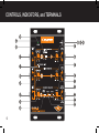
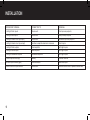
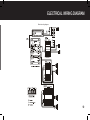
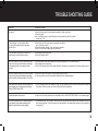
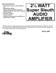
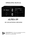
CXR-7
3 WAY ELECTRONIC CROSSOVER // OWNERS MANUAL
CONTENTS
• Specifications
3
• Features
4
• Controls, Indicators, and Terminal
5-8
• Installation
• Final System Check
• Troubleshooting Guide
9 - 10
11
12
2
SPECIFICATIONS
Power Source:
Input Current:
Distortion:
Frequency Response:
S/N Ratio:
Separation:
Crossover Frequencies (Continuously Variable)
Front High-Pass, X1:
X2:
Rear High-Pass:
Subwoofer:
Crossover Slope Rate
Low-Pass:
High-Pass:
Subwoofer Boost:
Input Impedance:
Output Impedance:
Output Gain:
Output Voltage Level:
Dimensions:
3
14.4 Volts DC negative Ground
0.5 Amp Max
0.01% THD @ 1 Volt Output Level
10Hz - 30Hz (-3dB)
95dB
60dB
25 - 400Hz
500 - 8000Hz
25 - 400Hz
25 - 400Hz
18dB per Octave 3rd Order Butter Worth
12dB per Octave 3rd Order Butter Worth
Single Octave 0dB to 12dB (Variable) at 45Hz
20K Ohms
100 Ohms
1:2 (+6dB)
7 Volts Max
5.5"(W) x 7.5"(L) x 1.75"(H)
FEATURES
• EXCLUSIVE INFINITE CROSSOVER DESIGN
• PARALLEL INPUT SWITCH
• ASYMMETRICAL ELECTRONIC CROSSOVER
DESIGN
For a source unit having a single pair of signal outputs an adapter
is needed to split the source signal for the front and rear inputs.
With the mobile electronic crossover, by engaging the parallel input
feature, an external adapter is no longer necessary.
• BASS BOOST CIRCUITRY WITH QUASI-PARAMETRIC EQUALIZATION
• FRONT/REAR INPUTS WITH FRONT/REAR/
SUBWOOFER OUTPUTS
A sealed enclosure causes a woofer’s frequency response to roll off
at a rate of 12dB per octave below the enclosure’s resonant frequency. The bass boost circuitry’s quasi-parametric equalization
provides a single octave boost of 12dB at 45Hz to ensure smooth
and accurate bass response.
The mobile electronic crossover features front and rear preamp inputs with front and rear outputs as well as constant subwoofer
output that is independent of the front/rear fader control on the
source unit.
• ADJUSTABLE OUTPUT LEVEL
• DC/DC REGULATED SWITCHING POWER SUPPLY
This power supply design provides constant voltage to the crossover regardless of the battery’s voltage to ensure consistent output performance at all times. This design also eliminates switching
noise sue to voltage fluctuation.
• STEREO/MONO SUBWOOFER
• GOLD PLATED RCA CONNECTORS
• FREQUENCY MULTIPLIER
The front high-pass section is equipped with frequency multiplier
switch that can be used to multiply the crossover frequency points.
With the additional selectable crossover points system setting becomes an art of precision.
FEATURES AND SPECIFICATIONS SUBJECT TO CHANGE AND OR IMPROVEMENT WITHOUT NOTICE
4
CONTROLS, INDICATORS, and TERMINALS
CXR-7
5
1. POWER INPUT TERMINAL (RED)
This wire should be connected to the positive terminal of your vehicle battery or other constant +12V source.
2. GROUND INPUT TERMINAL (BLACK)
This wire should be connected the vehicle’s chassis. Ensure that
you have a good connection. When connecting the wire make sure
that there is no paint or other insulator blocking the connection.
3. REMOTE TURN ON INPUT TERMINAL (ORANGE)
This wire should be connected to the remote turn on wire or antenna lead of the source unit. Should your system not have any turn on
leads, you can wire the remote terminal to an accessory lead which
turns on with your car’s ignition.
4. POWER INDICATOR
“OUT”: If the source unit has independent front and rear channel
outputs disengage the parallel input by sliding the switch to the
“out” position.
7. LEFT/RIGHT REAR CHANNEL SIGNAL INPUTS
Connect to the rear channel output of the source unit. MAKE SURE
THAT THE PARALLEL INPUT SWITCH IS AT THE “OUT” POSITION!
8. LEFT/RIGHT MIXED IN/OUT TERMINALS
AS INPUT TERMINAL: Connect to the subwoofer output of the
source unit.
AS OUTPUT TERMINAL: If running a multi cross-over system, connect to the front channel input terminal of the next electronic crossover.
This LED lights up when the internal switching power supply is activated and the unit is operational.
9. FRONT CHANNEL HIGH-PASS FREQUENCY
SELECTOR
5. LEFT/RIGHT FRONT CHANNEL SIGNAL INPUTS
Used to select the front channel high-pass crossover frequency
between 25Hz and 400Hz (or 500Hz and 8K Hz when its frequency
multiplier is in the “x20” position.
To be connected to the front channel output of the source unit.
6. PARALLEL INPUT SWITCH
“IN”: When the parallel input is in this position, the input signals
coming through the front channel signal inputs are split and directed to the front rear channels simultaneously (this feature is to
be used when the source unit has no separate front, rear, or subwoofer outputs).
10. REAR CHANNEL HIGH-PASS FREQUENCY
SELECTOR
For selection of rear channel high-pass crossover frequency between 25Hz and 400Hz.
6
CONTROLS, INDICATORS, and TERMINALS
11. FRONT CHANNEL HIGH-PASS FREQUENCY
MULTIPLIER
17. LEFT/RIGHT FRONT CHANNEL OUTPUT
TERMINALS
Positioning this switch at the “x20” position changes the range
of selectable crossover frequency for the front channel high-pass
from 25Hz - 400Hz to 500Hz - 8K Hz.
Connect to the front channel amplifier left/right inputs.
12. SUBWOOFER FREQUENCY SELECTOR
Allows you to set the low-pass crossover frequency for the subwoofer channel between 25Hz and 400Hz.
13. BASS SHAPER BOOST SWITCH
When activated this circuit provides a single octave boost of 12dB
at 45Hz to equalize the woofer enclosure.
14. PHASE INVERTER
Placing the switch at the “180” position shifts the subwoofer output’s signal 180° out of phase relative to the front and rear output
signals.
15. SUBWOOFER STEREO/MONO SWITCH
For selection of stereo or mono mode subwoofer output.
16. FRONT CHANNEL OUTPUT LEVEL CONTROL
For adjusting the front channel output signal level.
7
18. REAR CHANNEL OUTPUT LEVEL CONTROL
Used to adjust the rear channel output signal level.
19. LEFT/RIGHT REAR CHANNEL OUTPUT TERMINALS
Connect to the rear channel amplifier left/right inputs.
20. SUBWOOFER OUTPUT LEVEL CONTROL
Used to adjust the subwoofer channel output signal level.
21. LEFT/RIGHT SUBWOOFER OUTPUT TERMINALS
Connect to the subwoofer channel amplifier left/right inputs
22. SUBWOOFER OUTPUT LEVEL REMOTE CONTROL
TERMINAL
AMPLIFIER WIRING DIAGRAMS
Four-Channel “bi-amp” system (stereo front/rear)
Two-Channel “tri-amp” system
S
CXR -7
CXR-7
8
INSTALLATION
CROSSOVER TERMINAL
CONNECTED TO
TERMINAL
Left/right front inputs
Source unit
Front pre-amp outputs
Left/right rear inputs
Source unit
Rear pre-amp outputs
Left/right mixed in/out (as input)
Source unit
Subwoofer pre-amp outputs
Left/right mixed in/out (as output)
Another compatible electronic crossover
Front inputs
Left/right front outputs
Front amplifier
Left/right inputs
Left/right rear outputs
Rear amplifier
Left/right inputs
Left/right subwoofer outputs
Subwoofer amplifier
Left/right inputs
Power input terminal (b+)
Battery
Positive terminal
Ground input terminal (gnd)
Vehicle chassis
Bare metal spot
Remote turn-on input terminal
Source unit
Remove control wire or power antenna lead
9
ELECTRICAL WIRING DIAGRAM
Electrical wiring diagram
CXR -7
10
FINAL SYSTEM CHECK
1. Pre-Setting
A. Set front, rear and subwoofer amplifier input
gain to half of their maximum.
B. Preset the crossover frequencies and output
levels as follows.
Bi-Amp System
Front frequency selector:
Frequency multiplier:
Rear frequency selector:
Subwoofer frequency selector
Front output
Rear output
Subwoofer output level
160Hz
X1
160Hz
160Hz
10 o’clock position
10 o’clock position
12 o’clock position
Tri-Amp System
Front frequency selector:
Frequency multiplier:
Rear frequency selector:
Subwoofer frequency selector
Front output
Rear output
Subwoofer output level
200Hz
X 20
120Hz
120Hz
10 o’clock position
10 o’clock position
12 o’clock position
C. Preset the volume of the source unit to its
minimum (otherwise, when the source unit is
tuned on, the sudden surge of high power from
the amplifier might cause damage to the audio
components.
11
2. Turn the source unit on and slowly turn the volume up:
A. If no sound at all:
i) Turn the system off immediately.
ii) Check all connections (refer to page 9 for details).
iii) Use a volt/ohm meter to check your ground connections.
iv) Check your power input, ensure that it is properly connected to the positive terminal of a 12V power source.
v) Check to see that the remote on/off terminal is connected
properly to a +12V source.
vi) If everything is on order try turning the power off and then
on again. If problem persists, refer to the trouble shooting
guide on the next page for assistance.
B. Obvious distortion:
Turn the system off and refer to the trouble shooting guide
on the next page.
C. Out of phase problem (i.e. Abnormal Bass):
Turn the system off and refer to the trouble shooting guide
on the next page.
3. NOISE CHECK
Before mounting the mobile electronic crossover and the
other audio components permanently, please conduct the
following noise check:
1. Start the engine and turn on source unit.
2. Rev the engine and vary the audio volume to check for
radiated engine noise. If there is an alternator whining
noise or “tic-tic” noise, refer to the trouble shooting
guide on the next page. If the problem persists consult
your local retailer/installer for assistance.
3. If no unwanted noise is detected, double check all wiring
and cables to ensure safe placement. Then securely
tighten the mounting screws of the unit.
TROUBLE SHOOTING GUIDE
SYMPTOM
PROBABLE CAUSE
1. No power.
• Check all the ground, B+ and remote terminals for tight connection.
• Check all fuses.
• Use a volt/ohm meter to check all power wire connected to see if the system
is receiving +12V.
2. “Motorboating”: the unit power indicator going off repeatedly when the audio
system is on.
• Check if the unit B+ power input is connected to directly
to a +12V power source.
• Check the battery voltage. If low, recharge or replace it.
• Check if the unit has a good ground connection.
3. The unit heats up quickly even when the
audio system is at moderate volume.
• Check all ground connections.
• Check for speaker short.
4. When the engine is running the audio system
has a whining noise that remains unchanged
or disappears with the increase of audio
volume.
• Check all power wires and ensure that they are connected to a +12V power source.
• Check all ground connections.
• Check if the source unit and the mobile electronic crossover are grounded at the same reference point.
5. When the engine is running, the audio system
has a whining noise that increases or decreases
with the volume of all sources (radio, CD, or MP3).
• Install a 10 amp in-line filter on the red power wire of the unit.
• If whining persists, check the alternator diodes and the voltage regulator.
6. When the engine is running, the audio system has
has a whining noise that increases or decreases
with the CD/MP3 mode ONLY.
• This is commonly known as “radiated” noise. It is not caused by the unit and thus is beyond the scope of
this manual. Please contact your local retailer/installer for assistance.
7. Obvious distortion at low volume.
• Output level of various channels not compatible, refer to FINAL SYSTEM CHECK on the previous page.
8. Over all sound effect good, but bass is abnormal
(more bass at the two extreme settings of the
balance control that at the center setting).
• The subwoofers are “out-of-phase” with each other thus cancelling the bass when the balance control is
at the center position. Check the wiring from the amplifier to the subwoofers (positive [+] and negative [-]
to negative [-]).
12
// Features and specifications subject to change and or improvement without notice.
Though we tried our best to ensure that this manual is free and clear of errors please don’t hold us responsible for printing errors. //
www.cadencesound.com